FINAL DRAFT INTERNATIONAL STANDARD PROJET FINAL · PDF fileform fdis (iec)/formulaire fdis...
44
FORM FDIS (IEC)/FORMULAIRE FDIS (CEI) 2002-08-08 17B/1418/FDIS FINAL DRAFT INTERNATIONAL STANDARD PROJET FINAL DE NORME INTERNATIONALE Project number Numéro de projet IEC 60947-6-1, A3, Ed.1 IEC/TC or SC CEI/CE ou SC SC 17B Secretariat / Secrétariat France Submitted for parallel voting in CENELEC Soumis au vote parallèle au CENELEC Distributed on / Diffusé le 2005-05-20 Voting terminates on / Vote clos le 2005-07-22 Also of interest to the following committees Intéresse également les comités suivants Supersedes documents Remplace les documents 17B/1348/CDV – 17B/1387A/RVC Functions concerned Fonctions concernées Safety Sécurité EMC CEM Environment Environnement Quality assurance Assurance de la qualité INTERNATIONAL ELECTROTECHNICAL COMMISSION COMMISSION ÉLECTROTECHNIQUE INTERNATIONALE THIS DOCUMENT IS A DRAFT DISTRIBUTED FOR APPROVAL. IT MAY NOT BE REFERRED TO AS AN INTERNATIONAL STANDARD UNTIL PUBLISHED AS SUCH. IN ADDITION TO THEIR EVALUATION AS BEING ACCEPTABLE FOR INDUSTRIAL, TECHNOLOGICAL, COMMERCIAL AND USER PURPOSES, FINAL DRAFT INTERNATIONAL STANDARDS MAY ON OCCASION HAVE TO BE CONSIDERED IN THE LIGHT OF THEIR POTENTIAL TO BECOME STANDARDS TO WHICH REFERENCE MAY BE MADE IN NATIONAL REGULATIONS. CE DOCUMENT EST UN PROJET DIFFUSÉ POUR APPROBATION. IL NE PEUT ÊTRE CITÉ COMME NORME INTERNATIONALE AVANT SA PUBLICATION EN TANT QUE TELLE. OUTRE LE FAIT D'ÊTRE EXAMINÉS POUR ÉTABLIR S'ILS SONT ACCEPTABLES À DES FINS INDUSTRIELLES, TECHNOLOGIQUES ET COMMERCIALES, AINSI QUE DU POINT DE VUE DES UTILISATEURS, LES PROJETS FINAUX DE NORMES INTERNATIONALES DOIVENT PARFOIS ÊTRE EXAMINÉS EN VUE DE LEUR POSSIBILITÉ DE DEVENIR DES NORMES POUVANT SERVIR DE RÉFÉRENCE DANS LES RÈGLEMENTATIONS NATIONALES. Title Amendment 3 to IEC 60947-6-1, Ed. 1: Low-voltage switchgear and controlgear - Part 6-1: Multiple function equipment – Transfer switching equipment Titre Amendement 3 à la CEI 60947-6-1, Ed. 1: Appareillage à basse tension - Partie 6-1: Matériels à fonctions multiples - Matériels de connexion de transfert ATTENTION VOTE PARALLÈLE CEI – CENELEC L’attention des Comités nationaux de la CEI, membres du CENELEC, est attirée sur le fait que ce projet final de Norme internationale est soumis au vote parallèle. Un bulletin de vote séparé pour le vote CENELEC leur sera envoyé par le Secrétariat Central du CENELEC. ATTENTION IEC – CENELEC PARALLEL VOTING The attention of IEC National Committees, members of CENELEC, is drawn to the fact that this final Draft International Standard (DIS) is submitted for parallel voting. A separate form for CENELEC voting will be sent to them by the CENELEC Central Secretariat. Copyright © 2005 International Electrotechnical Commission, IEC. All rights reserved. It is permitted to download this electronic file, to make a copy and to print out the content for the sole purpose of preparing National Committee positions. You may not copy or "mirror" the file or printed version of the document, or any part of it, for any other purpose without permission in writing from IEC.
Transcript of FINAL DRAFT INTERNATIONAL STANDARD PROJET FINAL · PDF fileform fdis (iec)/formulaire fdis...
17B/1418/FDISFINAL DRAFT INTERNATIONAL STANDARD
PROJET FINAL DE NORME INTERNATIONALEProject number Numéro de projet
IEC 60947-6-1, A3, Ed.1
IEC/TC or SC CEI/CE ou SC SC 17B
Secretariat / Secrétariat France
Submitted for parallel voting in CENELEC Soumis au vote parallèle au CENELEC
Distributed on / Diffusé le 2005-05-20
Voting terminates on / Vote clos le 2005-07-22
Also of interest to the following committees Intéresse également les comités suivants
Supersedes documents Remplace les documents 17B/1348/CDV – 17B/1387A/RVC
Functions concerned Fonctions concernées
Safety Sécurité
EMC CEM
Environment Environnement
Quality assurance Assurance de la qualité
INTERNATIONAL ELECTROTECHNICAL COMMISSION COMMISSION ÉLECTROTECHNIQUE INTERNATIONALE
THIS DOCUMENT IS A DRAFT DISTRIBUTED FOR APPROVAL. IT MAY NOT BE REFERRED TO AS AN INTERNATIONAL STANDARD UNTIL PUBLISHED AS SUCH.
IN ADDITION TO THEIR EVALUATION AS BEING ACCEPTABLE FOR INDUSTRIAL, TECHNOLOGICAL, COMMERCIAL AND USER PURPOSES, FINAL DRAFT INTERNATIONAL STANDARDS MAY ON OCCASION HAVE TO BE CONSIDERED IN THE LIGHT OF THEIR POTENTIAL TO BECOME STANDARDS TO WHICH REFERENCE MAY BE MADE IN NATIONAL REGULATIONS.
CE DOCUMENT EST UN PROJET DIFFUSÉ POUR APPROBATION. IL NE PEUT ÊTRE CITÉ COMME NORME INTERNATIONALE AVANT SA PUBLICATION EN TANT QUE TELLE.
OUTRE LE FAIT D'ÊTRE EXAMINÉS POUR ÉTABLIR S'ILS SONT ACCEPTABLES À DES FINS INDUSTRIELLES, TECHNOLOGIQUES ET COMMERCIALES, AINSI QUE DU POINT DE VUE DES UTILISATEURS, LES PROJETS FINAUX DE NORMES INTERNATIONALES DOIVENT PARFOIS ÊTRE EXAMINÉS EN VUE DE LEUR POSSIBILITÉ DE DEVENIR DES NORMES POUVANT SERVIR DE RÉFÉRENCE DANS LES RÈGLEMENTATIONS NATIONALES.
Title Amendment 3 to IEC 60947-6-1, Ed. 1: Low-voltage switchgear and controlgear - Part 6-1: Multiple function equipment – Transfer switching equipment
Titre Amendement 3 à la CEI 60947-6-1, Ed. 1: Appareillage à basse tension - Partie 6-1: Matériels à fonctions multiples - Matériels de connexion de transfert
ATTENTION VOTE PARALLÈLE
CEI – CENELEC L’attention des Comités nationaux de la CEI, membres du CENELEC, est attirée sur le fait que ce projet final de Norme internationale est soumis au vote parallèle. Un bulletin de vote séparé pour le vote CENELEC leur sera envoyé par le Secrétariat Central du CENELEC.
ATTENTION IEC – CENELEC
PARALLEL VOTING The attention of IEC National Committees, members of CENELEC, is drawn to the fact that this final Draft International Standard (DIS) is submitted for parallel voting. A separate form for CENELEC voting will be sent to them by the CENELEC Central Secretariat.
Copyright © 2005 International Electrotechnical Commission, IEC. All rights reserved. It is permitted to download this electronic file, to make a copy and to print out the content for the sole purpose of preparing National Committee positions. You may not copy or "mirror" the file or printed version of the document, or any part of it, for any other purpose without permission in writing from IEC.
FORM FDIS (IEC)/FORMULAIRE FDIS (CEI) 2002-08-08

60947-6-1 Amend. 3/FDIS © IEC – 2 –
CONTENTS FOREWORD...........................................................................................................................4
1 Scope and object..............................................................................................................7 2 Normative references .......................................................................................................8 3 Terms and definitions, symbols and abbreviations ............................................................9
3.1 Switching devices....................................................................................................9 3.2 Operation of TSE................................................................................................... 10 3.3 Main contact positions ........................................................................................... 11 3.4 Symbols and abbreviations.................................................................................... 11
4 Classification .................................................................................................................. 12 5 Characteristics ............................................................................................................... 12
5.1 Summary of characteristics ................................................................................... 12 5.2 Type of equipment................................................................................................. 12 5.3 Rated and limiting values for the main circuit......................................................... 13 5.4 Utilization category................................................................................................ 15 5.5 Control circuits ...................................................................................................... 15 5.6 Auxiliary circuits .................................................................................................... 16
6 Product information ........................................................................................................ 16 6.1 Nature of information............................................................................................. 16 6.2 Marking ................................................................................................................. 16 6.3 Instructions for installation, operation and maintenance ........................................ 17
7 Normal service, mounting and transport conditions......................................................... 17 8 Constructional and performance requirements ................................................................ 17
8.1 Constructional requirements .................................................................................. 17 8.2 Performance requirements .................................................................................... 17 8.3 Electromagnetic compatibility (EMC) ..................................................................... 22
9 Tests .............................................................................................................................. 23 9.1 Kinds of tests ........................................................................................................ 23 9.2 Compliance with constructional requirements ........................................................ 23 9.3 Performance.......................................................................................................... 24 9.4 Routine tests ......................................................................................................... 36 9.5 EMC tests ............................................................................................................. 36
Annex A (normative) – Assignment of utilization categories based on the results of tests ..... 40 Annex B (informative) – Items subject to agreement between manufacturer and user ........... 42
Figure 1 – Test circuit for connection to normal and alternative supplies ............................... 39 Figure 2 – Test circuit for the verification of making and breaking capacities on three poles .40 Figure 3 – Test circuit for the verification of making and breaking capacities on two poles .... 40

60947-6-1 Amend. 3/FDIS © IEC – 3 –
Table 1 – Utilization categories ............................................................................................. 15 Table 2 – Verification of making and breaking capacity – Conditions for making and breaking corresponding to the utilization categories .............................................................. 19 Table 3 – Verification of operational performance – Conditions for making and breaking corresponding to the utilization categories ............................................................................ 20 Table 4 – Value of the test current for the verification of the ability to operate under short-circuit conditions .......................................................................................................... 21 Table 5 – Acceptance criteria................................................................................................ 23 Table 6 – List of type tests (overall scheme of test sequences) ............................................. 25 Table 7 – List of type tests (referred to by their subclause numbers) to which a given derived TSE shall be submitted............................................................................................. 26 Table 8 – Number and duration of operating cycles for the making and breaking capacity test ......................................................................................................................... 30 Table 9 – Number and duration of operating cycles for the electrical and mechanical operational performance tests for operation A utilization categories ...................................... 32 Table 10 – Number and duration of operating cycles for the electrical and mechanical operational performance tests for operation B utilization categories ...................................... 32 Table A.1 – Equivalence between utilization categories used in some IEC 60947 product standards ................................................................................................................. 42

60947-6-1 Amend. 3/FDIS © IEC – 4 –
INTERNATIONAL ELECTROTECHNICAL COMMISSION ___________
LOW-VOLTAGE SWITCHGEAR AND CONTROLGEAR –
Part 6-1: Multiple function equipment –
Transfer switching equipment
FOREWORD 1) The International Electrotechnical Commission (IEC) is a worldwide organization for standardization comprising
all national electrotechnical committees (IEC National Committees). The object of IEC is to promote international co-operation on all questions concerning standardization in the electrical and electronic fields. To this end and in addition to other activities, IEC publishes International Standards, Technical Specifications, Technical Reports, Publicly Available Specifications (PAS) and Guides (hereafter referred to as “IEC Publication(s)”). Their preparation is entrusted to technical committees; any IEC National Committee interested in the subject dealt with may participate in this preparatory work. International, governmental and non-governmental organizations liaising with the IEC also participate in this preparation. IEC collaborates closely with the International Organization for Standardization (ISO) in accordance with conditions determined by agreement between the two organizations.
2) The formal decisions or agreements of IEC on technical matters express, as nearly as possible, an international consensus of opinion on the relevant subjects since each technical committee has representation from all interested IEC National Committees.
3) IEC Publications have the form of recommendations for international use and are accepted by IEC National Committees in that sense. While all reasonable efforts are made to ensure that the technical content of IEC Publications is accurate, IEC cannot be held responsible for the way in which they are used or for any misinterpretation by any end user.
4) In order to promote international uniformity, IEC National Committees undertake to apply IEC Publications transparently to the maximum extent possible in their national and regional publications. Any divergence between any IEC Publication and the corresponding national or regional publication shall be clearly indicated in the latter.
5) IEC provides no marking procedure to indicate its approval and cannot be rendered responsible for any equipment declared to be in conformity with an IEC Publication.
6) All users should ensure that they have the latest edition of this publication.
7) No liability shall attach to IEC or its directors, employees, servants or agents including individual experts and members of its technical committees and IEC National Committees for any personal injury, property damage or other damage of any nature whatsoever, whether direct or indirect, or for costs (including legal fees) and expenses arising out of the publication, use of, or reliance upon, this IEC Publication or any other IEC Publications.
8) Attention is drawn to the Normative references cited in this publication. Use of the referenced publications is indispensable for the correct application of this publication.
9) Attention is drawn to the possibility that some of the elements of this IEC Publication may be the subject of patent rights. IEC shall not be held responsible for identifying any or all such patent rights.
International Standard IEC 60947-6-1 has been prepared by subcommittee 17B: Low-voltage switchgear and controlgear, of IEC technical committee 17: Switchgear and controlgear.
This second edition cancels and replaces the first edition published in 1989, amendment 1 (1994), and amendment 2 (1997). This edition incorporates Amendment 3 which was not published separately.
The document 17B/XXX/XXX, circulated to the National Committees as amendment 3, led to the publication of this standard.

60947-6-1 Amend. 3/FDIS © IEC – 5 –
The text of this standard is based on first edition, amendment 1, amendment 2 and the following documents:
FDIS Report on voting
17B/XXXX/FDIS 17B/XXXX/RVD
Full information on the voting for the approval of this standard can be found in the report on voting indicated in the above table.
This part of IEC 60947shall be used in conjunction with IEC 60947-1: General rules.
The provisions of the general rules dealt with in IEC 60947-1 are applicable to this part of IEC 60947, where specifically called for. Clauses and subclauses, tables, figures and annexes of the general rules thus applicable are identified by reference to IEC 60947-1 (e.g. 1.2.3 of IEC 60947-1, Table 4 of IEC 60947-1 or Annex A of IEC 60947-1, etc.).
This publication has been drafted in accordance with the ISO/IEC Directives, Part 2.
A vertical line in the margin shows where the base publication has been modified by the amendment 3.
IEC 60947 consists of the following parts, under the general title Low-voltage switchgear and controlgear:
Part 1: General rules Part 2: Circuit-breakers Part 3: Switches, disconnectors, switch-disconnectors and fuse-combination units Part 4-1: Contactors and motor-starters – Electromechanical contactors and motor-starters Part 4-2: Contactors and motor-starters – AC semiconductor motor controllers and starters Part 4-3: Contactors and motor-starters – AC semiconductor controllers and contactors for
non-motor loads Part 5-1: Control circuit devices and switching elements – Electromechanical control circuit
devices Part 5-2: Control circuit devices and switching elements – Proximity switches Part 5-3: Control circuit devices and switching elements – Requirements for proximity
devices with defined behaviour under fault conditions (PDF) Part 5-4: Control circuit devices and switching elements – Method of assessing the
performance of low-energy contacts – Special tests Part 5-5: Control circuit devices and switching elements – Electrical emergency stop device
with mechanical latching function Part 5-6: Control circuit devices and switching elements – DC interface for proximity
sensors and switching amplifiers (NAMUR) Part 5-7: Control circuit devices and switching elements – Requirements for proximity
devices with analogue output

60947-6-1 Amend. 3/FDIS © IEC – 6 –
Part 5-8: Control circuit devices and switching elements – Three-position enabling switches1
Part 5-9: Control circuit devices and switching elements – Flow rate switches1 Part 6-1: Multiple function equipment – Automatic transfer switching equipment Part 6-2: Multiple function equipment – Control and protective switching devices (or
equipment) (CPS) Part 7-1: Ancillary equipment – Terminal blocks for copper conductors Part 7-2: Ancillary equipment – Protective conductor terminal blocks for copper conductors Part 7-3: Ancillary equipment – Safety requirements for fuse terminal blocks Part 7-3: Ancillary equipment – Safety requirements for fuse terminal blocks Part 8: Control units for built-in thermal protection (PTC) for rotating electrical machines
The committee has decided that the contents of this publication will remain unchanged until the maintenance result date2 indicated on the IEC web site under "http://webstore.iec.ch" in the data related to the specific publication. At this date, the publication will be
• reconfirmed, • withdrawn, • replaced by a revised edition, or • amended.
————————— 1 Under consideration.
2 The National Committees are requested to note that for this publication the maintenance result date is 2008.

60947-6-1 Amend. 3/FDIS © IEC – 7 –
LOW-VOLTAGE SWITCHGEAR AND CONTROLGEAR –
Part 6-1: Multiple function equipment – Transfer switching equipment
1 Scope and object
This part of IEC 60947applies to transfer switching equipment (TSE) to be used in power systems with interruption of the supply to the load during transfer, the rated voltage of which does not exceed 1 000 V a.c. or 1 500 V d.c.
It covers:
– manually operated transfer switching equipment (MTSE); – remote operated transfer switching equipment (RTSE); – automatic transfer switching equipment (ATSE).
It covers TSE provided with or without an enclosure.
Devices necessary for the control (e.g. control switches, etc.) and the protection (e.g. circuit-breakers, etc.) of a TSE are covered by the relevant IEC standards.
NOTE TSE used only for emergency lighting may be subject to specific rules and/or legal requirements and are not, therefore, covered by this standard.
The object of this part of IEC 60947 is to state:
1) The characteristics of the equipment: a) specific equipment; b) equipment the main part of which being devices covered by other IEC 60947 product
standards. 2) The conditions of the equipment with respect to:
a) operation for which the equipment is intended; b) operation and behaviour in case of specified abnormal conditions, for example, short-
circuit; c) dielectric properties.
3) The tests intended to confirm that these conditions have been met and the methods for performing these tests.
4) The data to be marked on the equipment and provided by the manufacturer.

60947-6-1 Amend. 3/FDIS © IEC – 8 –
2 Normative references
The following referenced documents are indispensable for the application of this document. For dated references, only the edition cited applies. For undated references, the latest edition of the referenced document (including any amendments) applies.
IEC 60695-11-10:1999, Fire hazard testing – Part 11-10: Test flames – 50 W horizontal and vertical flame test methods Amendment 1 (2003)
IEC 60947-1:2004, Low-voltage switchgear and controlgear – Part 1: General rules
IEC 60947-2:2003, Low-voltage switchgear and controlgear – Part 2: Circuit-breakers
IEC 60947-3:1999, Low-voltage switchgear and controlgear – Part 3: Switches, disconnectors, switch-disconnectors and fuse-combination units Amendment 1 (2001)
IEC 60947-4-1:2000, Low-voltage switchgear and controlgear – Part 4-1: Contactors and motor-starters – Electromechanical contactors and motor-starters Amendment 1 (2002)
IEC 60947-4-2:1999, Low-voltage switchgear and controlgear – Part 4-2: Contactors and motor-starters – AC semiconductor motor controllers and starters Amendment 1 (2001)
IEC 60947-4-3:1999, Low-voltage switchgear and controlgear – Part 4-3: Contactors and motor-starters – AC semiconductor controllers and contactors for non-motor loads
IEC 60947-6-2:2002, Low-voltage switchgear and controlgear – Part 6-2: Multiple function equipment – Control and protective switching devices (or equipment) (CPS)
IEC 61000-4-2:1995, Electromagnetic compatibility (EMC) – Part 4-2: Testing and measurement techniques – Electrostatic discharge immunity test Amendment 1 (1998) Amendment 2 (2000)
IEC 61000-4-3:2002, Electromagnetic compatibility (EMC) – Part 4-3: Testing and measurement techniques – Radiated, radio-frequency, electromagnetic field immunity test Amendment 1 (2002)
IEC 61000-4-4:1995, Electromagnetic compatibility (EMC) – Part 4-4: Testing and measurement techniques – Electrical fast transient/burst immunity test Amendment 1 (2000) Amendment 2 (2001)
IEC 61000-4-5:1995, Electromagnetic compatibility (EMC) – Part 4-5: Testing and measurement techniques – Surge immunity test Amendment 1 (2000)
IEC 61000-4-6:2003, Electromagnetic compatibility (EMC) – Part 4-6: Testing and measurement techniques – Immunity to conducted disturbances, induced by radio-frequency fields Amendment 1 (2004)

60947-6-1 Amend. 3/FDIS © IEC – 9 –
CISPR 11:2003, Industrial, scientific and medical (ISM) radio-frequency equipment – Electromagnetic disturbance characteristics – Limits and methods of measurement Amendment 1 (2004)
3 Terms and definitions, symbols and abbreviations
For the purpose of this part of IEC 60947 the relevant terms and definitions given in Clause 2 of IEC 60947-1 and the following additional definitions shall apply:
Reference A
Alternative position ................................................................................................... 3.3.2 Automatic transfer switching equipment (ATSE)........................................................ 3.1.4
C Contact transfer time ................................................................................................ 3.2.5
D Derived transfer switching equipment (derived TSE) ................................................. 3.1.5
F Frequency supply deviation ...................................................................................... 3.2.4
M Manually operated transfer switching equipment (MTSE) .......................................... 3.1.2 Monitored supply deviation of ATSE ......................................................................... 3.2.2
N Normal position......................................................................................................... 3.3.1
O Off position ............................................................................................................... 3.3.3 Off-time .................................................................................................................... 3.2.9 Operating sequence of ATSE.................................................................................... 3.2.1 Operating transfer time ............................................................................................. 3.2.6
R Remotely operated transfer switching equipment (RTSE).......................................... 3.1.3 Return transfer time .................................................................................................. 3.2.8
T Total operating time .................................................................................................. 3.2.7 Transfer switching equipment (TSE) ......................................................................... 3.1.1
V Voltage supply deviation ........................................................................................... 3.2.3 3.1 Switching devices
3.1.1 transfer switching equipment TSE equipment containing one or more switching devices for disconnecting load circuits from one supply and connecting to another supply

60947-6-1 Amend. 3/FDIS © IEC – 10 –
3.1.2 manually operated transfer switching equipment MTSE transfer switching equipment operated manually
3.1.3 remotely operated transfer switching equipment RTSE transfer switching equipment operated remotely
NOTE RTSE may have an optional feature for local operation.
3.1.4 automatic transfer switching equipment ATSE self-acting transfer switching equipment
NOTE 1 ATSE normally includes all necessary devices for monitoring and transferring operations.
NOTE 2 ATSE may have an optional feature for manual operation.
3.1.5 derived transfer switching equipment derived TSE TSE in which the main part are device(s) fulfilling requirements of other IEC 60947 product standards
NOTE 1 For convenience, derived TSE may be called derived ATSE, derived MTSE or derived RTSE.
NOTE 2 For convenience, parts other than main parts (e.g. those intended to control the TSE: control switches, mechanical interlocking devices, …) are called other parts.
3.2 Operation of TSE
3.2.1 operating sequence of ATSE automatic transfer of a load from the normal supply to an alternative supply in the event of a monitored supply deviation with an automatic return of the load to the normal supply when restored
NOTE 1 The transfer may be with or without a predetermined time delay and may include an off position.
NOTE 2 In the case of both the normal and the alternative supplies being present, the ATSE assumes the normal supply position.
3.2.2 monitored supply deviation of ATSE variation in the power supply characteristics which signals the ATSE to operate when a deviation from the specified limits occurs
EXAMPLE Abnormal changes in voltage or frequency of the supply are supply deviations.
3.2.3 voltage supply deviation change or loss of voltage of the normal power supply
3.2.4 frequency supply deviation change in frequency from the normal operating frequency of the normal supply

60947-6-1 Amend. 3/FDIS © IEC – 11 –
3.2.5 contact transfer time time measured from the parting of one set of main contacts from one power supply to the closing of a second set of main contacts on an alternative power supply
3.2.6 operating transfer time time measured from the instant of the monitored supply deviation to the closing of main contacts on an available alternative supply source, exclusive of any purposely introduced time delay
3.2.7 total operating time sum of operating transfer time and any purposely introduced time delay
3.2.8 return transfer time time from the instant when the normal supply is fully restored to the instant when the set of main contacts is closed on the normal supply, plus any purposely introduced time delay
3.2.9 off-time time measured during transfer from the instant of final arc extinction, under the conditions producing the longest arcing time, in all poles to the closing of main contacts on another supply
NOTE Any purposely introduced time delay would be included within the off-time.
3.3 Main contact positions
3.3.1 normal position contact position of the equipment when there is no deviation of the normal supply
3.3.2 alternative position contact position of the equipment when the load circuit is switched on the alternative (emergency) supply in the event of a monitored supply deviation of the normal supply
3.3.3 off position contact position of the equipment when the load circuit is not switched on any supply
NOTE This position results from either automatic tripping caused by a fault in the load circuit or intentional interruption of the automatic transfer function.
3.4 Symbols and abbreviations
EMC Electromagnetic compatibility Icm Rated short-circuit making capacity (5.3.6.2) Icn Rated short-circuit breaking capacity (5.3.6.3) Icw Rated short-time withstand current (5.3.6.1) Ie Rated operational current (5.3.2) Iu Rated uninterrupted current (5.3.2)
SCPD Short-circuit protective device Ue Rated operational voltage (5.3.1.1) Ui Rated insulation voltage (5.3.1.2)

60947-6-1 Amend. 3/FDIS © IEC – 12 –
Uimp Rated impulse withstand voltage (5.3.1.3) Ur Power frequency or d.c. recovery voltage (Table 2)
4 Classification
Transfer switching equipment is classified according to:
a) their short-circuit capability:
− class PC: TSE that is capable of making and withstanding, but is not intended for breaking short-circuit currents; NOTE Contactors can be used in class PC if they fulfil the test requirements of class PC.
− class CB: TSE provided with over-current releases and the main contacts of which are capable of making and are intended for breaking short-circuit currents;
− class CC: TSE that is capable of making and withstanding, but is not intended for breaking short-circuit currents. TSE based on devices fulfilling the requirements of IEC 60947-4-1;
b) the method of controlling the transfer:
− manually operated switching equipment (MTSE);
− remote operated switching equipment (RTSE);
− automatic transfer switching equipment (ATSE).
5 Characteristics
5.1 Summary of characteristics
Wherever practicable the characteristics of the TSE shall be stated as follows:
– Type of equipment (5.2). – Rated and limiting values for the main circuit (5.3). – Utilization category (5.4). – Control circuits (5.5). – Auxiliary circuits (5.6).
Where the TSE uses IEC 60947 products, the relevant characteristics from those standards may also be additionally used.
5.2 Type of equipment
The following shall be stated:
– class and transfer control method of the equipment (see Clause 4); – number of poles; – kind of current; – operating sequence.

60947-6-1 Amend. 3/FDIS © IEC – 13 –
5.3 Rated and limiting values for the main circuit
Subclause 4.3 of IEC 60947-1 applies. However, minimum values for 5.3.6.1, 5.3.6.3 and 5.3.6.4 are given in Table 4.
5.3.1 Rated voltages
5.3.1.1 Rated operational voltage (Ue)
Subclause 4.3.1.1 of IEC 60947-1 applies.
5.3.1.2 Rated insulation voltage (Ui)
Subclause 4.3.1.2 of IEC 60947-1 applies.
5.3.1.3 Rated impulse withstand voltage (Uimp)
Subclause 4.3.1.3 of IEC 60947-1 applies.
5.3.2 Rated operational current (Ie)
The rated operational current of TSE is the rated uninterrupted current (Iu). See 4.3.2.4 of IEC 60947-1.
5.3.3 Rated frequency
Subclause 4.3.3 of IEC 60947-1 applies.
5.3.4 Uninterrupted duty
Subclause 4.3.4.2 of IEC 60947-1 applies.
5.3.5 Rated making and breaking capacities
The rated making and breaking capacities are the values of current, stated by the manufacturer, which the transfer equipment can satisfactorily make and break under specified conditions. Unless stated otherwise, they are given in terms of a steady state current value. During the making operation, the peak value of the current on contact closing may be higher than the peak value of the steady state current depending on the characteristics of the test circuit (load) and the instant of closing on the voltage wave.
The rated making and breaking capacities are stated with reference to the rated operational voltage, the rated operational current and the utilization category according to Table 2.
For a.c., the rated making and breaking capacities are expressed by the r.m.s. value of the a.c. component of the current.
5.3.6 Short-circuit characteristics
5.3.6.1 Rated short-time withstand current (Icw)
The rated short-time withstand current is the value of short-time withstand current stated by the manufacturer which the equipment can carry under the test conditions specified in 9.3.4.3.

60947-6-1 Amend. 3/FDIS © IEC – 14 –
For a.c., the value of the current is the r.m.s. value of the a.c. component and the highest peak value in any one phase shall be not less than n times this r.m.s. value, the ratio n being given in Table 16 of IEC 60947-1.
The minimum value of the short-time withstand current is given in column 2 of Table 4.
NOTE Additional lower values of short-time withstand current for longer durations may be stated by the manufacturer.
The minimum durations are:
– 3 half-cycles of the rated frequency or 0,025 s for d.c. for rated operational currents up to and including 400 A;
– 3 cycles of the rated frequency or 0,05 s for d.c. for rated operational currents higher than 400 A.
5.3.6.2 Rated short-circuit making capacity (Icm)
The rated short-circuit making capacity is the value of short-circuit making capacity assigned by the manufacturer for the rated operational voltage at rated frequency and at a specified power-factor (or time-constant). It is expressed as the maximum prospective peak current.
For class CB TSE and for a.c., the rated short-circuit making capacity shall be not less than highest value of short-circuit breaking capacity, multiplied by the ratio n of Table 16 of IEC 60947-1. The manufacturer may assign a higher value of short-circuit making capacity.
For d.c., the rated short-circuit making capacity shall be not less than its rated short-circuit breaking capacity, on the assumption that the steady-state short-circuit current is constant.
A rated short-circuit making capacity implies that the TSE shall be able to make the current corresponding to that rated capacity at an applied voltage up to and including that corresponding to 105 % of the rated operational voltage.
5.3.6.3 Rated short-circuit breaking capacity (Icn)
The rated short-circuit breaking capacity is the value of short-circuit breaking capacity assigned by the manufacturer for the rated operational voltage, at rated frequency and at a specified power-factor (or time-constant).
It is expressed as the value of the prospective breaking current (r.m.s. value of the a.c. component in the case of a.c.).
The minimum value of the rated short-circuit breaking capacity is given in column 2 of Table 4. The manufacturer may assign a higher value of breaking capacity.
A rated short-circuit breaking capacity implies that a Class CB TSE shall be able to break any current up to the rated capacity.
5.3.6.4 Rated conditional short-circuit current
The rated conditional short-circuit current is the value of prospective current, stated by the manufacturer, which the TSE, protected by a specified short-circuit protective device (SCPD), can satisfactorily withstand for the operating time of this device under the test conditions specified in 9.3.4.4.

60947-6-1 Amend. 3/FDIS © IEC – 15 –
The minimum value of the prospective current is given in column 2 of Table 4.
Details of the specified short-circuit protective device shall be indicated by the manufacturer. They shall include the type, rating, characteristics and, for current limiting devices, the maximum peak current and the I 2t corresponding to the value of the prospective current.
NOTE 1 For a.c., the rated conditional short-circuit current is expressed by the r.m.s. value of the a.c. component.
NOTE 2 The short-circuit protective device may either form an integral part of the equipment or be a separate unit.
5.4 Utilization category
TSE may be assigned one or more of the standard utilization categories given in Table 1 at one or more rated utilization voltages.
The designation of utilization categories is completed by the suffix A or B, according to the number of operations (see Tables 8, 9 and 10) required by the application.
TSE assigned any utilization category shall comply with the rated making and breaking capacity (Table 2) and the electrical and mechanical operational performance requirements (Table 3) corresponding to the assigned utilization category.
Table 1 – Utilization categories
Utilization category Nature of current
Operation A Operation B
Typical applications
Alternating current
AC-31A
AC-32A
AC-33A
AC-35A
AC-36A
AC-31B
AC-32B
AC-33B
AC-35B
AC-36B
Non-inductive or slightly inductive loads
Switching of mixed resistive and inductive loads, including moderate overloads
Motor loads or mixed loads including motors, resistive loads and up to 30 % incandescent lamp loads
Electric discharge lamp loads
Incandescent lamp loads
Direct current
DC-31A
DC-33A
DC-36A
DC-31B
DC-33B
DC-36B
Resistive loads
Motor loads or mixed loads including motors
Incandescent lamp load
For TSE for which the main parts are covered by other IEC 60947 product standards, utilization categories defined in these product standards may be used as equivalent as those defined in Table 1, see Annex A.
5.5 Control circuits
Subclause 4.5 of IEC 60947-1 applies with the following additions for monitored supply (see 3.2.2).
5.5.1 Electro-mechanical devices controlling the main circuit
The minimum and maximum values of voltage or voltage and frequency operating limits shall be stated by the manufacturer. These limits shall correspond to the limits for the transfer control devices.

60947-6-1 Amend. 3/FDIS © IEC – 16 –
5.5.2 Transfer control devices
The manufacturer shall state the following:
a) the voltage and frequency deviations at which transfer should occur; b) the contact transfer time, the operating transfer time, the return transfer time range and
the off time range (if any).
5.6 Auxiliary circuits
Subclause 4.6 of IEC 60947-1 applies.
6 Product information
6.1 Nature of information
The following information shall be given by the manufacturer:
Identification:
a) the manufacturer's name or trade mark; b) type designation or serial number; c) number of this part of IEC 60947 if the manufacturer claims compliance;
Characteristics:
d) class of equipment: PC, CB or CC; e) rated operational voltage(s); f) utilization category and rated operational current at the rated operational voltage; g) either value of the rated frequency, for example: 50 Hz or the indication "d.c." (or the
symbol ); h) rated short-circuit making capacity for class PC/CC, and i) rated short-time withstand current, where applicable; j) rated conditional short-circuit current and associated SCPD (see 5.3.6.4), where
applicable; k) rated short-circuit making and breaking capacities for Class CB; l) number of main contact positions; m) monitored supply deviation and operating limits; n) operating sequence and time delays, if any, and the position of time delays in the
operating sequence; o) rated impulse withstand voltage; p) environment A or B (see 7.3.1 of IEC 60947-1); q) special requirements, if applicable, for example shielded or twisted conductors; NOTE Unshielded or untwisted conductors are considered as normal installation conditions.
r) off-time for derived TSE (see 3.2.9).
6.2 Marking
Each TSE shall be marked in a durable manner with the following data. The markings shall be on the equipment itself or on a nameplate or nameplates attached to the equipment and shall be located so that they are visible and legible when the equipment is installed.

60947-6-1 Amend. 3/FDIS © IEC – 17 –
Data a) to j) and o) of 6.1 shall be marked on the equipment, where applicable, or on a nameplate.
Data k) to n) and p) to r) may be marked on the equipment and shall be given in the manufacturer's literature.
6.3 Instructions for installation, operation and maintenance
Subclause 5.3 of IEC 60947-1 applies.
Information shall be provided by the manufacturer to advise the user on the measures to be taken with regard to the TSE, if any, concerning EMC.
7 Normal service, mounting and transport conditions
Clause 6 of IEC 60947-1 applies.
8 Constructional and performance requirements
8.1 Constructional requirements
Subclause 7.1 of IEC 60947-1 applies with the following additions.
8.1.1.1 Resistance to abnormal heat and fire
Parts of insulating materials necessary to retain current-carrying parts in position shall conform to the glow wire test of 8.2.1.1.1 of IEC 60947-1 at a test temperature of 850 °C.
When tests on materials are used, the flammability category of IEC 60695-11-10 shall be given by the manufacturer for each material to be tested.
8.2 Performance requirements
8.2.1 Operating conditions
Subclause 7.2.1 of IEC 60947-1 applies with the following additions:
8.2.1.1 Operating mechanism
a) TSE shall be capable of operating for all conditions of their marked intended performance. b) The operating mechanism shall be interlocked to prevent simultaneous connection to both
normal and alternative supplies under all conditions. Removal of doors or access panels shall not result in defeating the interlocking mechanism.
c) For class PC/CC TSE, the operating mechanism shall be such that the load circuit cannot remain permanently switched off from both the normal and the alternative supplies. However, there may be an intentional timed off period after which the transfer is completed and, in some cases, a rest position may be provided. Class CB of TSE may have an intentional timed off period and/or an off position.
d) For TSE in which an electromechanical device operates the main contacts, the main contacts shall close and open without jerks i.e., without noticeable deceleration.
60947-6-1 Amend. 3/FDIS © IEC – 18 –
Verification shall be made in compliance with 9.3.3.1. This requirement does not apply to stored energy operated devices.
8.2.1.2 Controls, sequence and limits of operation
a) Overvoltage condition The coil of a control electromagnet shall be capable of withstanding, without damage, 110 % of the rated operational voltage for the maximum time it is normally energized in service or until it attains a constant temperature.
b) Undervoltage condition The coil of electromagnetic voltage sensing relay, if used, shall withstand, without damage, 95 % of its rated pull-in voltage for 4 h.
c) Operation on loss of supply voltage The ATSE shall transfer the load from the normal supply to the available alternative supply upon the interruption for a predetermined period of any or all of the monitored phases of the normal supply and return to the normal supply when it is restored.
d) Operation on reduction of supply voltage If the TSE is provided with means to initiate transfer from the normal to the alternative supply upon reduction of the voltage of the main supply, the transfer shall be initiated within the limits stated by the manufacturer.
e) Transfer on availability of alternative voltage or voltage-frequency If voltage or voltage and frequency sensing circuits are provided to determine availability of the alternative supply, transfer shall be effected within the limits specified by the manufacturer.
f) Operating times Any time delay or off-time provided in the total operating transfer time, from the normal to the alternative or the alternative to the normal supply, shall be within the limits specified by the manufacturer.
Compliance with the above requirements is verified by the tests of 9.3.3.2.

60947-6-1 Amend. 3/FDIS © IEC – 19 –
Table 2 – Verification of making and breaking capacity – Conditions for making and breaking corresponding to the utilization categories
Make and break conditions
Utilization category I/Ie Ur/Ue cos ϕ a
On-time b
s
Cycle time
min
Number of operating
cycles
AC
AC-31A AC-31B
AC-32A AC-32B
AC-33A AC-33B
AC-35A AC-35B
AC-36A AC-36B
1,5
3,0
10
3,0
1,5 d
1,05
1,05
1,05
1,05
1,05
0,80
0,65 h
0,50 d
0,05
0,05
0,05
0,05
0,05
c c c c c
c c c c c
L/R e ms
DC
DC-31A DC-31B
DC-33A DC-33B
DC-36A DC-36B
1,5
4,0
1,5 d
1,05
1,05
1,05
g
2,5 d
0,05
0,05
0,05
c c c
c f c f c f
I = Current made and broken. The making current is expressed in d.c. or a.c. r.m.s. symmetrical values but it is understood that, for AC-36A, AC-36B, DC-36A and DC-36B categories, the actual peak value during the making operation may assume a higher value than the symmetrical peak value.
Ie = Rated operational current. Ur = Power frequency or d.c. recovery voltage. Ue = Rated operational voltage.
a Tolerance for cos ϕ is ±0,05. b Time may be less than 0,05 s provided that the contacts are allowed to become properly seated before re-
opening. c See Table 8. d Tests shall be carried out with an incandescent light load in accordance with the general test conditions as
specified in 9.3.3.5.1. e Tolerance for L/R is ±15 %. f If the polarity is not marked, half the number of operating cycles is effected with one polarity and half with
reverse polarity. g No intentional time constant. h Cos ϕ = 0,45 for Ie ≤ 100 A and cos ϕ = 0,35 for Ie > 100 A.

60947-6-1 Amend. 3/FDIS © IEC – 20 –
Table 3 – Verification of operational performance – Conditions for making and breaking corresponding to the utilization categories
Make and break conditions
Utilization category I/Ie Ur/Ue cos ϕ a
On-time b
s
Cycle time
min
Number of operating
cycles
AC
AC-31A AC-31B
AC-32A AC-32B
AC-33A AC-33B
AC-35A AC-35B
AC-36A AC-36B
1,0
1,0
2,0 h
2,0 h
1,0 d
1,05
1,05
1,05
1,05
1,05
1,0
0,8
0,8
0,8 d
0,05
0,05
0,05
0,05
0,05
c c c c c
c c c c c
L/R e
ms
DC
DC-31A DC-31B
DC-33A DC-33B
DC-36A DC-36B
1,0
2,5 i
1,0 d
1,05
1,05
1,05
g
2,5 d
0,05
0,05
0,05
c c c
c f c f c f
I = Current made and broken. The making current is expressed in d.c. or a.c. r.m.s. symmetrical values but it is understood that, for AC-36A, AC-36B, DC-36A and DC-36B categories, the actual peak value during the making operation may assume a higher value than the symmetrical peak value.
Ie = Rated operational current. Ur = Power frequency or d.c. recovery voltage. Ue = Rated operational voltage.
a Tolerance for cos ϕ is ±0,05. b Time may be less than 0,05 s provided that the contacts are allowed to become properly seated before re-
opening. c See Tables 9 and 10. d Tests shall be carried out with an incandescent light load in accordance with the general test conditions as
specified in 9.3.3.5.1. e Tolerance for L/R is ±15%. f If the polarity is not marked, half the number of operating cycles is effected with one polarity and half with
reverse polarity. g No intentional time constant. h One-half of the operating cycles shall be done at I/Ie = 1, except for AC-33B and AC-35B where all operating
cycles shall be done at I/Ie = 1. i One-half of the operating cycles shall be done at I/Ie = 1, except for DC-33B where all operating cycles shall
be at I/Ie = 1.
8.2.2 Temperature rise
When tested at the highest rated operational current under the conditions described in 9.3.3.3, TSE shall not attain a temperature at any point to constitute a fire hazard or to damage any materials employed in the device and shall not exceed the temperature rise values stated in 7.2.2 of IEC 60947-1.
60947-6-1 Amend. 3/FDIS © IEC – 21 –
8.2.3 Dielectric properties
Subclause 7.2.3 of IEC 60947-1 applies.
8.2.4 Ability to make and break under no-load, normal load and overload conditions
8.2.4.1 Making and breaking capacities
TSE shall make and break currents without failure under the conditions stated in Table 2 for the required utilization categories when tested as specified in 9.3.3.5. See also Clause A.3.
8.2.4.2 Operational performance
8.2.4.2.1 Electrical operational performance
Following the making and breaking capacity test, TSE shall make and break current without failure under the test conditions stated in Table 3 for the required utilization categories when tested according to 9.3.3.6.2. See also Clause A.3.
8.2.4.2.2 Mechanical operational performance
Following the electrical operational performance test, TSE shall perform, without failure, the number of no-load operations given in Tables 9 and 10 when tested as specified in 9.3.3.6.3. See also Clause A.3.
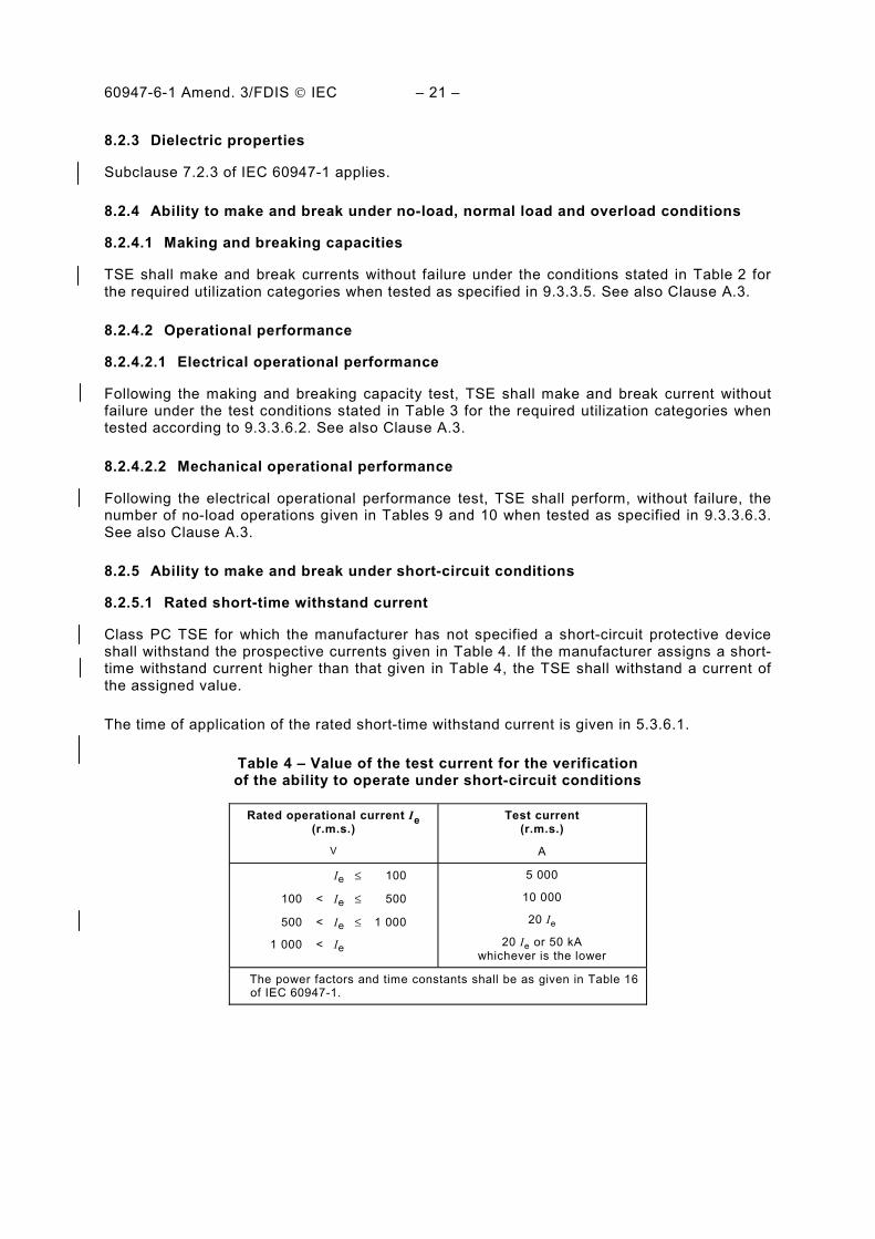
8.2.5 Ability to make and break under short-circuit conditions
8.2.5.1 Rated short-time withstand current
Class PC TSE for which the manufacturer has not specified a short-circuit protective device shall withstand the prospective currents given in Table 4. If the manufacturer assigns a short-time withstand current higher than that given in Table 4, the TSE shall withstand a current of the assigned value.
The time of application of the rated short-time withstand current is given in 5.3.6.1.
Table 4 – Value of the test current for the verification of the ability to operate under short-circuit conditions
Rated operational current Ie (r.m.s.)
V
Test current (r.m.s.)
A
Ie ≤ 100
100 < Ie ≤ 500
500 < Ie ≤ 1 000
1 000 < Ie
5 000
10 000
20 Ie
20 Ie or 50 kA whichever is the lower
The power factors and time constants shall be as given in Table 16 of IEC 60947-1.

60947-6-1 Amend. 3/FDIS © IEC – 22 –
8.2.5.2 Rated conditional short-circuit current
Class PC TSE for which the manufacturer has specified a short-circuit protective device (SCPD) shall withstand the application of the prospective test current given in Table 4 until the SCPD has opened the circuit.
If the manufacturer assigns a conditional short-circuit current higher than that given in Table 4, the TSE shall also withstand this assigned value of current.
SCPD used shall comply with its product standard at ratings not lower than those assigned in this part of IEC 60947.
8.2.5.3 Rated short-circuit making capacity
TSE class PC for which the manufacturer has not assigned a rated conditional short-circuit current (or an Iq following the conditions of 9.3.4.4) and TSE class CB shall make the test currents in accordance with Table 4 and 5.3.6.2 (see also footnote a of Table 6).
If the manufacturer assigns a short-circuit making capacity greater than the test current given in Table 4, the TSE shall also make this assigned value of current.
8.2.5.4 Rated short-circuit breaking capacity
Class CB TSE shall break the test currents given in Table 4.
If the manufacturer assigns a short-circuit breaking capacity greater than the test current given in Table 4, the TSE shall also break this assigned value of current.
8.3 Electromagnetic compatibility (EMC)
8.3.1 General
Subclause 7.3.1 of IEC 60947-1 applies with the following additions.
The main part of derived TSE, where installed as specified by the manufacturer regarding EMC, shall not to be tested according to this part of IEC 60947 when fulfilling EMC requirements of the same or higher severity.
Power-frequency magnetic field tests are not required because the devices are naturally submitted to such fields. Immunity is demonstrated by the successful completion of the operational performance capability tests (see 9.3.3.5 and 9.3.3.6).
8.3.2 Immunity
Subclause 7.3.2 of IEC 60947-1 applies with Table 5 and the following addition.
The test values and procedures are given in 9.5.

60947-6-1 Amend. 3/FDIS © IEC – 23 –
Table 5 – Acceptance criteria
Item Acceptance criteria (performance criteria during tests)
1 2 3
Operation of power and control circuits
No mal-operation Temporary mal-operation which cannot cause tripping; unintentional separation or closure of contacts is not accepted
Unintentional separation or closure of contacts
Self-recoverable
Operation of displays and auxiliary circuits
No changes to visible display information
Temporary visible changes, e.g. unwanted lED illumination
Permanent loss of display information
Only slight light intensity fluctuations of LEDs or movement of characters
No mal-operation of auxiliary contacts
Mal-operation of auxiliary contacts
8.3.3 Emission
Subclause 7.3.3 of IEC 60947-1 applies with the following addition.
The test values and procedures are given in 9.5.
9 Tests
9.1 Kinds of tests
9.1.1 General
Subclause 8.1.1 of IEC 60947-1 applies.
9.1.2 Type tests
Type tests to verify compliance of TSE with this part of IEC 60947are defined in Tables 6 and 7.
9.1.3 Routine tests
Subclause 8.1.3 of IEC 60947-1 applies.
Routine tests are stated in 9.4.
9.1.4 Sampling tests
Sampling tests for clearance verification according to 8.3.3.4.3 of IEC 60947-1 are under consideration.
9.2 Compliance with constructional requirements
Subclause 8.1 of this part of IEC 60947 and 8.2.1 to 8.2.4 of IEC 60947-1 apply.

60947-6-1 Amend. 3/FDIS © IEC – 24 –
9.3 Performance
9.3.1 Test sequences
For test sequences, refer to Tables 6 and 7, and the following:
1) Tests a) to e) and test m) can be performed on one or separate samples. 2) Tests f), g) and h) are to be performed on one sample in the sequence given in the table. 3) Tests i) to l) are to be performed on one sample (other than that used for sequence II) in
the order given in the table.
All the tests can be done on one sample, if requested or agreed by the manufacturer. In this case, the test sequence shall be a) to m).
9.3.2 General test conditions
9.3.2.1 General requirements
The condition of the equipment for the tests shall be as stated in 8.3.2 of IEC 60947-1.
NOTE It is not necessary to test values for all test values corresponding to assigned categories. See Annex A.
The tests of 9.3.3.3, 9.3.4.2, 9.3.4.3 and 9.3.4.4, shall be performed as follows:
a) If the construction of the TSE is such that there is no significant difference between the normal and the alternative positions (e.g., contact size and force, opening, bus bar size and length, clearance to enclosure etc.) that would influence the test results, the tests can be done in one position of the switch.
b) If it can be determined that one position represents a more difficult case, the tests are to be done in that position.

60947-6-1 Amend. 3/FDIS © IEC – 25 –
Table 6 – List of type tests (overall scheme of test sequences)
Test sequence Tests Ref. Applicable to class of TSE
N° sample
c
a) Constructional requirements 9.2
b) Operation 9.3.3.1
c) Controls, sequence and limits of operation 9.3.3.2
d) Temperature rise 9.3.3.3
I General
performance characteristics
e) Dielectric properties 9.3.3.4
PC/CC CB 1
f) Making and breaking capacities 9.3.3.5
g) Operational performance capability (electrical) 9.3.3.6.2
- Dielectric withstand verification 9.3.3.4 II
Operating performance
h) Operational performance capability (mechanical)
9.3.3.6.3
PC/CC CB 1
i) Short-circuit making capacity 9.3.4.2.2 PC/CC a
CB
- Dielectric withstand verification d 9.3.3.4 PC/CC CB
j) Short-circuit breaking capacity 9.3.4.2.3 − CB
- Dielectric withstand verification d 9.3.3.4 − CB
k) Short time withstand current 9.3.4.3 PC/CC a
−
- Dielectric withstand verification d 9.3.3.4 PC/CC −
l) Conditional short-circuit current 9.3.4.4 PC/CC b
−
- Dielectric withstand verification 9.3.3.4 PC/CC CB
III Verification of short-circuit capabilities
- Temperature rise verification 9.3.4.3 PC/CC CB
1
IV Environmental
tests
m) Electromagnetic compatibility 9.5 PC/CC CB 1
a This test is not required if the manufacturer has assigned a conditional short-circuit current. b This test is made only if the manufacturer assigns a short-circuit protective device. c Tests can be made on one sample only at the manufacturer's discretion. d Test to be made only if not required after a further test on the same sample.

60947-6-1 Amend. 3/FDIS © IEC – 26 –
Table 7 – List of type tests (referred to by their subclause numbers) to which a given derived TSE shall be submitted
Test sequence Tests Ref. Applicable to Class of TSE N°
samplef
PC/CC CB
Main Othera
Main Othera
IEC
609
47-3
IEC
609
47-4
IEC
609
47-2
IEC
609
47-3
IEC
609
47-
6-2
a) Constructional requirements
9.2 X X
b) Operation 9.3.3.1 X X X X X X X
c) Controls, sequence and limits of operation
9.3.3.2 X X X X X X X
d) Temperature rise h 9.3.3.3 X X X X X X X
I General
performance characteristics
e) Dielectric properties 9.3.3.4 X X X X X X X
1
f) Making and breaking capacities including interlock function test
9.3.3.5 X X g
X X X g
g) Operational performance capability (electrical)
9.3.3.6.2 X g
X g
X g
X g
X g
- Dielectric withstand verification e
9.3.3.4 X X X X X X X
II Operating
performance
h) Operational performance capability (mechanical)
9.3.3.6.3 X X g
X X X X g
X
1
i) Short-circuit making capacity
9.3.4.2.2 X
c X c
X c
X c
X c
j) Short-circuit breaking capacity
9.3.4.2.3 N/A N/A X c
X c
X c
k) Short time withstand current
9.3.4.3 X b d
X b d
X d
N/A N/A N/A
l) Conditional short-circuit current
9.3.4.4 X c
X c
N/A N/A N/A
- Dielectric withstand verification e
9.3.3.4 X X X X X X X
III Verification of short-circuit capabilities
- Temperature rise verification e
9.3.4.3 X X X X X X X
1
IV Environmental
tests
m) Electromagnetic compatibility
9.5 X X X X X X X 1
N/A: Not applicable.

60947-6-1 Amend. 3/FDIS © IEC – 27 –
a For convenience, parts other than main parts (e.g. those intended to control the TSE: control switches, mechanical interlocking devices, …) are called other parts. b See also 8.2.5.1 and 9.3.4.3 for applicability. c If applicable (see 8.2.5.3, 9.3.4.2 and/or 9.3.4.4). d Only if mounted in a dedicated enclosure. e Only if operating performance and/or short-circuit test required. f Tests can be made on one sample only at the manufacturer's discretion. g If applicable (see 9.3.3.5.3 and/or 9.3.3.6.1). h Tests required only if current carrying capacity of the internal conductors are less than that required by Table 9 and 10 of IEC 60947-1.
9.3.3 Performance under no-load, normal load and overload conditions
9.3.3.1 Operation
Operating mechanism
It shall be verified that TSE operates as stated in 8.2.1.1, items a), b), and c)
For TSE in which electromagnets operate the main contacts, the main contacts shall open or close without jerks when the control supply voltage is increased from zero, or decreased from its rated value Us, as appropriate, at the rate of 0,2 Us per second. This test does not apply to stored energy operated devices.
9.3.3.2 Controls, sequence and limits of operation
9.3.3.2.1 General
TSE shall be tested to verify their performance according to the requirements given in 8.2.1.2. Test details are given in the following subclauses.
9.3.3.2.2 Overvoltage condition
The normal and the alternative supply terminals of ATSE and the coil of control electromagnet of RTSE shall be energized at 110 % of the rated operational voltage for a time sufficient for the coils of electromagnets which are energized in service to attain a constant temperature.
9.3.3.2.3 Undervoltage condition of electromagnetic voltage sensing relays
The coils of voltage sensing relays, if any, shall be energized at 95 % of their rated pull in value (the relays shall not pull in) and held at this voltage for 4 h.
9.3.3.2.4 Operation on loss of supply voltage
The ATSE shall be connected (without load) to both circuits of the normal and alternative supplies of rated voltage and frequency, as shown in Figure 1. The ATSE shall be in the normal supply position.

60947-6-1 Amend. 3/FDIS © IEC – 28 –
With one of the monitored phases of the normal supply disconnected, the ATSE shall transfer to the alternative supply. with the normal supply phase reconnected, the ATSE shall return to the normal supply position.
This test shall be repeated on each of the monitored normal supply conductors disconnected in turn.
9.3.3.2.5 Operation on reduction of supply voltage
If voltage deviation sensing of the normal supply is provided, the TSE shall be connected as in 9.3.3.2.4 and the voltage on each normal supply monitored conductor reduced in turn to the value stated by the manufacturer and then restored to the original value. This test shall be repeated by reducing the voltage on all the phases of the normal supply simultaneously and by restoring it to its original value.
In each of the tests, the TSE shall transfer to the alternative position when the voltage is reduced and return to the normal supply position when the voltage is restored.
9.3.3.2.6 Transfer on availability of alternative voltage or voltage-frequency
If voltage and frequency sensing of the alternative supply is provided, the TSE shall be connected as in Figure 1. The operating values of voltage and frequency at which the transfer from the normal supply to the alternative supply occurs shall be verified in accordance with item a) or b) below as applicable.
a) For voltage sensing of the alternative supply With the alternative supply voltage below the value stated by the manufacturer and the normal supply at the rated voltage, disconnect one of the lines of the normal supply and then gradually increase the voltage of the alternative supply. Transfer shall occur from the normal to the alternative supply within the voltage limits stated by the manufacturer.
b) For voltage-frequency sensing of the alternative supply With the normal supply at the rated voltage and one of its supply lines disconnected: 1) starting with the alternative supply frequency below the pickup value, maintain its
voltage at the minimum specified value and gradually increase its frequency. Transfer to the alternative supply shall occur within the frequency limits stated by the manufacturer.
2) starting with the alternative supply voltage below the pickup value, maintain its frequency at the minimum specified value and gradually increase its voltage. Transfer to the alternative supply shall occur within the voltage limits stated by the manufacturer.
9.3.3.3 Temperature rise
The temperature rise test shall be done as stated in 8.3.3.3 of IEC 60947-1 and shall comply with the requirements stated in 8.2.2.
9.3.3.4 Dielectric properties
Subclause 8.3.3.4 of IEC 60947-1 applies with the following modifications.

60947-6-1 Amend. 3/FDIS © IEC – 29 –
9.3.3.4.1 Type tests
Subclause 8.3.3.4.1 of IEC 60947-1 applies with the addition of:
− the following sentence, at the end of item 1): The metal foil shall not be applied for power frequency withstand verification after making, breaking, operational and short-circuit tests.
− the following sentence, after the second paragraph of item 2) b): Control circuits of a TSE connected between phases which have been subjected to Uimp test voltages lower than those specified in 7.2.3.1 and 8.3.3.4.2 of IEC 60947-1 may be disconnected for the test.
− the following sentence, after the first paragraph of item 2) c) ii): In the case where the control circuit, normally connected to the main circuit, is disconnected (according to 8.3.3.4.1, item 2) b)), the method used to maintain the main contacts closed shall be indicated in the test report, where relevant.
− the following sentence at the end of 8.3.3.4.1, item 8): For equipment suitable for isolation, the leakage current shall be measured through each pole with the contacts in the open position, at a test voltage of 1,1 Ue and shall not exceed 0,5 mA.
Verification of impulse withstand voltage across open contacts is not required for equipment not suitable for isolation (see 8.3.3.4.1, item 2) c) iv) of IEC 60947-1).
9.3.3.5 Making and breaking capacities
9.3.3.5.1 General test conditions
Subclause 8.3.3.5.1 of IEC 60947-1 applies.
9.3.3.5.2 Test circuit
Subclause 8.3.3.5.2 of IEC 60947-1 applies except that the connection of TSE in the test circuit on the supply side shall be as shown in Figure 2 or Figure 3.
For utilization categories AC-36A or AC-36B and DC-36A or DC-36B the load shall be such that a rated operational current is obtained together with a short duration transient current during making, as given in Table 2. The transient making current shall attain its peak value within 5 ms after the circuit is closed. Any suitable load may be used such as:
a) incandescent lamps; b) non-inductive resistor, or resistors connected in parallel with a capacitor or, c) resistive load with part of the resistance short-circuited for a short duration in order to
produce the transient peak current.
Tests shall be sequenced by external controls independent of monitored supply deviations.

60947-6-1 Amend. 3/FDIS © IEC – 30 –
9.3.3.5.3 Derived TSE
The verification of making and breaking capacities according to 9.3.3.5.4 need not be made where TSE already fulfilled the requirements of relevant IEC 60947 product standards for utilization categories corresponding to equivalent or more severe tests (see also Annex A). However, such TSE shall be submitted to the test conducted with both normal supply circuit parts and alternative supply circuit parts energized/operated simultaneously, except for IEC 60947-4-1 and IEC 60947-6-2 derived TSE (requirements covered by the reversing tests specified in IEC 60947-4-1 and IEC 60947-6-2). The off-time measured shall be greater than the value given by the manufacturer but not less than 50 ms.
9.3.3.5.4 Verification of making and breaking capacities
a) TSE shall make and break the test current at the voltage and power factor or at the time constant corresponding to its utilization category as given in Table 2. The number of operating cycles and the cycle time shall be as given in Table 8. An operating cycle consists of making and breaking the test current on both the main and the alternative supply contacts. 20 % additional operation, with a minimum of two operations, shall be conducted with both normal supply circuit parts and alternative supply circuit parts energised/operated simultaneously. The total operating transfer time, the time delay and the timed off-time shall be measured and shall be within the limits stated by the manufacturer. Tests of 9.3.3.5.4 shall be carried out only on TSE which do not fulfil conditions given in 9.3.3.5.3. Only the 20 % operation, with a minimum of two operations, shall be conducted with both normal supply circuit parts and alternative supply circuit parts energised/operated simultaneously for derived TSE submitted to this test, according to 9.3.3.5.3.
Table 8 – Number and duration of operating cycles
for the making and breaking capacity test
Number of operating cycles
Operation A Operation B
Rated operational current Ie
A AC-31A, AC-32A, AC-33A, AC-35A,
AC-36A
DC-31A, DC-33A, DC-36A
AC-31B, AC-35B, AC-36B
DC-31B, DC-36B
AC-32B, AC-33B
DC-33B
Duration of operating cycle
min a
0 < Ie ≤ 300 50 12 5 1
300 < Ie ≤ 400 50 12 5 2
400 < Ie ≤ 630 50 12 5 3
630 < Ie ≤ 800 50 12 5 4
800 < Ie ≤ 1 600 50 12 5 5
1 600 < Ie ≤ 2 500 25 6 5 5
2 500 < Ie 3 3 3 5 a The duration of operating cycle may be reduced with the consent of the manufacturer.

60947-6-1 Amend. 3/FDIS © IEC – 31 –
b) The test current shall be not less than the value indicated in Table 2. c) The on-time in each contact position shall be 0,05 s unless automatic tripping of the
overload protective device occurs. d) All sensing and control relays shall be energized at their rated voltage(s) and the relay
contacts shall make and break their normal load(s). e) Time-delay, undervoltage and frequency sensing relays may be bypassed to facilitate
testing of the main circuit contacts. f) During the test there shall be no failure, and the fuse specified in 8.3.3.5.2 of IEC 60947-1
shall not have blown.
After the test the TSE shall operate in the intended normal manner.
9.3.3.6 Operational performance capability
9.3.3.6.1 Derived TSE
The verification according to 9.3.3.6.2 and 9.3.3.6.3 need not be made where TSE already fulfilled the requirements of relevant IEC 60947 product standards for utilization categories corresponding to equivalent or more severe tests (see also Annex A). The off-time measured shall be greater than the value given by the manufacturer but not less than 50 ms.
Where the total number of operating cycles for operational performance tests, given in Table 9 or Table 10, as appropriate, is higher than the total number of operations for conventional operational performance, for the appropriate utilization category given in the product standard relevant to the main part of the TSE, mechanical operational performance tests shall be carried out on the complete TSE according to 9.3.3.6.3.
Mechanical and/or electrical interlocking means of TSE derived from IEC 60947-2 or IEC 60947-3 shall be submitted to the total number of operating cycles given in Table 9. These tests may be made separately or grouped with other tests.
Parts of derived TSE (e.g. auxiliary devices) for which the main part is not tested according to this subclause shall be submitted to the total number of operating cycles given in Table 9 or Table 10, as appropriate. These tests may be made separately or grouped with other tests.
9.3.3.6.2 Electrical operational performance
a) The TSE shall make and break the test current at the voltage and power factor or the time constant corresponding to its utilization category as given in Table 3. No maintenance or replacement of parts is permitted. The number of operating cycles and their duration shall be as given in Tables 9 and 10. An operating cycle consists of making and breaking the test current on both the main and the alternative supply contacts.
b) The test circuit and operation requirements given in 9.3.3.5.2 and 9.3.3.5.4, items c), d), e) and f) apply.
c) The test current shall not be less than the value indicated in Table 3.

60947-6-1 Amend. 3/FDIS © IEC – 32 –
d) After the test, the TSE shall be capable of withstanding the dielectric tests of 8.3.3.4.1, item 4), of IEC 60947-1. For class CB TSE suitable for isolation having an operational voltage Ue greater than 50 V, the leakage current shall be measured through each pole with the contacts in the open position, at a test voltage of 1,1 Ue, and shall not exceed 2 mA.
e) After the tests, the off-time shall comply with the manufacturer’s claim, but shall not be less than 50 ms.
Table 9 – Number and duration of operating cycles for the electrical and mechanical
operational performance tests for operation A utilization categories
Number of operating cycles Rated operational current Ie
A
Duration of operating cycle
min a Without current With current Total
0 < Ie ≤ 100 1 − 6 000 6 000
100 < Ie ≤ 300 1 − 6 000 6 000
300 < Ie ≤ 400 1 − 4 000 4 000
400 < Ie ≤ 630 1 1 000 2 000 3 000
630 < Ie ≤ 800 1 1 000 2 000 3 000
800 < Ie ≤ 1 600 2 1 500 1 500 3 000
1 600 < Ie ≤ 2 500 4 2 000 1 000 3 000
2 500 < Ie 4 2 000 1 000 3 000
a The duration of operating cycle may be reduced with the consent of the manufacturer.
Table 10 – Number and duration of operating cycles for the electrical and mechanical operational performance tests for operation B utilization categories
Number of operating cycles Rated operational current Ie
A
Duration of operating cycle
min a Without current With current Total
0 < Ie ≤ 100 1 4 500 1 500 6 000
100 < Ie ≤ 300 1 5 000 1 000 6 000
300 < Ie ≤ 400 1 3 000 1 000 4 000
400 < Ie ≤ 630 1 2 000 1 000 3 000
630 < Ie ≤ 800 1 2 500 500 3 000
800 < Ie ≤ 1 600 3 2 500 500 3 000
1 600 < Ie ≤ 2 500 6 1 500 500 2 000
2 500 < Ie 6 1 500 500 2 000
a The duration of operating cycle may be reduced with the consent of the manufacturer.

60947-6-1 Amend. 3/FDIS © IEC – 33 –
9.3.3.6.3 Mechanical operational performance
TSE shall perform, without maintenance or replacement of parts, the number of cycles of operation without current given in Table 9 or Table 10, as the case may be.
For the test, the sensing and control relays required to be energized shall be energized at their rated quantities. Time delay, undervoltage and frequency sensing relays may be bypassed to facilitate testing.
After the test, the TSE shall pass the test of 9.3.3.2.4.
For derived TSE, where the tests are needed (see 9.3.3.6.1), the number of operating cycles shall be the total number of operating cycles given in Table 9 or Table 10, as appropriate. These tests may be made separately or grouped with other tests.
After the tests, the time delay between opening a circuit and closing the other indicated by the manufacturer shall not have a significant variation.
9.3.4 Performance under short-circuit conditions
9.3.4.1 Test circuit for the verification of short-circuit ratings
The general requirements given in 8.3.4.1.1 of IEC 60947-1 apply. Details of the test circuit and calibration shall be as given in 8.3.4.1.2 to 8.3.4.1.8 of IEC 60947-1.
9.3.4.2 Verification of short-circuit making and breaking capacities
9.3.4.2.1 General
TSE derived from IEC 60947-2 having:
− a short-circuit making capacity Icm (of IEC 60947-2) higher than or equal to the making capacity of TSE according to 8.2.5.3 and as specified in 5.3.6.2, and
− a short-circuit breaking capacity Icu (of IEC 60947-2) higher than or equal to Icn according to 8.2.5.4 and as specified in 5.3.6.3,
shall not be submitted to this test.
TSE derived from IEC 60947-6-2 having:
− a rated service short-circuit breaking capacity Ics (of IEC 60947-6-2), multiplied by the factor n given in Table 16 of IEC 60947-1, higher than or equal to Icm according to 8.2.5.3 and as specified in 5.3.6.2, and
− a rated service short-circuit breaking capacity Ics (of IEC 60947-6-2) higher than or equal to Icn according to 8.2.5.4 and as specified in 5.3.6.3,
shall not be submitted to this test.
9.3.4.2.2 Rated short-circuit making capacity
a) The prospective test current(s) shall be as specified in 8.2.5.3. b) The device operating the main contacts shall be energized in the normal manner. c) Tests shall be sequenced by external controls independent of monitored supply
deviations.

60947-6-1 Amend. 3/FDIS © IEC – 34 –
d) For the test position of TSE, see 9.3.2.1. e) The current shall be made by closing the TSE and maintained until the TSE has opened
the circuit (Class CB) or for the time specified in 5.3.6.1. f) After the test the TSE shall meet the requirements of 9.3.4.3, item c).
9.3.4.2.3 Rated short-circuit breaking capacity
This test shall be made on class CB TSE only.
Unless otherwise stated, short-circuit releases shall be set at maximum (time and current) for all tests.
If the mechanism is electrically controlled, it shall be supplied at the minimum voltage. In addition, electrically controlled mechanisms shall be energized via the appropriate TSE control circuits complete with switching devices. lt shall be verified that the class CB TSE operates correctly on no-load when it is operated under the above conditions.
Class CB TSE shall be tested in free air.
If a class CB TSE may be used in specified dedicated enclosures and has been tested in free air, it shall be additionally tested in the smallest of such enclosures stated by the manufacturer, using a new sample at Ue max.
Details of these tests, including the dimensions of the enclosure, shall be stated in the test report.
NOTE A dedicated enclosure is an enclosure designed and dimensioned to contain one class CB TSE only.
However, if a class CB TSE may be used in specified dedicated enclosures and has been tested in the smallest of such enclosures stated by the manufacturer, the tests in free air need not be made provided that such enclosure is bare metallic, without insulation. Details, including the dimensions of the enclosure, shall be stated in the test report.
Maintenance or replacement of parts is not permitted.
If, for convenience of testing, it appears useful to increase the severity of a test (for example to adopt a higher frequency of operation in order to reduce the duration of the test), this shall not be made without the consent of the manufacturer.
a) Class CB TSE shall be tested as specified in 9.3.4.2.2 except that, with TSE closed, the current shall be applied by a separate switching device until the TSE has opened the circuit.
b) After the test, the TSE shall meet the requirements of 9.3.4.3, item c).
9.3.4.3 Verification of the ability to carry rated short-time withstand current
This test shall be made on class PC TSE only.
TSE derived from IEC 60947-3 and having a rated short-time withstand current Icw higher than or equal to the prospective current specified in 8.2.5.2 shall not be submitted to this test.

60947-6-1 Amend. 3/FDIS © IEC – 35 –
a) Class PC TSE shall be tested at the rated operational voltage in an appropriate circuit calibrated to produce a prospective current given in Table 4 and, if a higher value is stated, of higher value than the short-time withstand current and the corresponding time stated by the manufacturer. For TSE in which electromagnets operate the main contacts, these shall be held closed by energizing the coil at its rated voltage from a separate source.
b) With the TSE closed, the current shall be applied by a separate switching device, the current maintained as specified in 5.3.6.1 and interrupted by the separate switching device.
c) After the test, the following conditions shall be met: 1) The TSE contacts shall close and open by their normal means and be capable of
carrying the rated operational current. A temperature rise test shall be carried out on the same TSE, without maintenance, according to 9.3.3.3, and the temperature rise shall not exceed the values given in Tables 2 and 3 of IEC 60947-1, increased by 10 K.
2) The fuse connected to the enclosure or the wire mesh shall not blow. 3) There shall be no breakage of the TSE to the extent that the integrity of the mounting
of live parts is impaired. 4) For enclosed TSE, the door shall be prevented by its latching means, without
additional locking means, from being blown open, but deformation of the door alone is not considered to constitute a failure, provided the requirements of degree of protection IP2X are met (see Annex C of IEC 60947-1).
5) The TSE shall be capable of withstanding the dielectric tests of 8.3.3.4.1, item 4), of IEC 60947-1.
9.3.4.4 Verification of the rated conditional short-circuit current
This test shall be made on class PC/CC TSE only.
For class PC, TSE derived from IEC 60947-4-1 and having passed without welding a conditional short-circuit current Iq test greater than the prospective current specified in 8.2.5.2 shall not be submitted to this test.
For class CC, TSE derived from IEC 60947-4-1 and having passed a conditional short-circuit current Iq test greater than the prospective current specified in 8.2.5.2 shall not be submitted to this test.
TSE derived from IEC 60947-3 and having a conditional short-circuit current greater than the prospective current specified in 8.2.5.2 shall not be submitted to this test.
a) TSE shall be tested in series with a short-circuit protective, device (SCPD) indicated by the manufacturer (see 5.3.6.4). SCPD used for the test shall be selected to ensure the maximum values of Ip and I2t for the type, rating and characteristics of the SCPD specified. To obtain these maximum values, it may be necessary to use an SCPD of rating larger than specified. If fuses of the same interchangeable size and rating have several characteristics with different maximum Ip and I2t values, fuses having the highest Ip and I2t values shall be used.
Where it is physically impossible to install a larger SCPD in the space normally occupied by the stated SCPD, this larger SCPD shall be connected in the same position in the circuit, with a link of negligible impedance by-passing the specified SCPD.

60947-6-1 Amend. 3/FDIS © IEC – 36 –
b) The prospective test current(s) shall be as specified in 8.2.5.2. In case of more than one value of short-circuit current, a new sample may be used for each current value.
c) Tests shall be sequenced by external controls independent of monitored supply deviations.
d) For the test condition of TSE, see 9.3.2.1. e) With the TSE and the SCPD closed, the current shall be applied by a separate switching
device and the current maintained until the SCPD has opened the circuit. The operating device may be energized from a separate source.
f) This test shall be followed by another on the same sample, the current being made by closing the TSE, and maintained until the SCPD has opened the circuit.
g) After the test, the conditions specified in 9.3.4.3, item c) shall be met.
9.4 Routine tests
Routine tests shall be made on new and clean TSE and shall consist of:
a) Verification of the operating mechanism as stated in 9.3.3.1. b) Verification of controls, sequence and limits as stated in 9.3.3.2.4, 9.3.3.2.5 and 9.3.3.2.6. c) Verification of dielectric withstand according to 8.3.3.4.2 of IEC 60947-1.
NOTE The combined test of 8.3.3.4.2 of IEC 60947-1 is permitted.
9.5 EMC tests
9.5.1 General
Subclauses 8.3.2.1, 8.3.2.3 and 8.3.2.4 of IEC 60947-1 apply with the following additions.
With the agreement of the manufacturer more than one EMC test or all EMC tests may be conducted on one and the same sample, which may initially be new or may have passed test sequences according to 9.3.1. The sequence of the EMC tests may be as convenient.
The test report shall include any special measures that have been taken to achieve compliance, for example the use of shielded or special cables. If auxiliary equipment is used with the device in order to comply with immunity or emission requirements, it shall be included in the report.
The test sample shall be in the open or closed position, whichever is worse, and shall be operated with the rated control supply.
In accordance with 8.3.1, parts of derived TSE already tested according to other product standards shall not be re-tested. Other parts incorporating electronic circuits shall be tested.
9.5.2 Immunity
9.5.2.1 General
The tests of Table 23 of IEC 60947-1 are required. Special requirements are specified in 9.5.2.2 to 9.5.2.8. If during the EMC tests, conductors are to be connected to the test sample, the cross-section and the type of the conductors is optional but shall be in accordance with the manufacturer's literature.

60947-6-1 Amend. 3/FDIS © IEC – 37 –
9.5.2.2 Electrostatic discharge
The test shall be conducted using the methods of IEC 61000-4-2.
Except for metallic parts for which contact discharge is made, only air discharge is required. Test levels shall be 8 kV air discharge and 4 kV contact discharge. Ten positive and 10 negative pulses shall be applied to each selected point, the time interval between each successive single discharge being 1 s.
The tests are made only on the parts of the equipment which are normally accessible to the operator in normal service.
Except for necessary terminals (for example control supply terminals) connections are not required to be made to other terminals.
Tests are not possible if the device is an open frame or of degree of protection IP00. In this case, the manufacturer shall attach a label to the unit advising of the possibility of damage due to static discharges.
The equipment shall comply with performance criterion 1.
9.5.2.3 Radio-frequency electromagnetic field
The tests are divided into frequency ranges, 0,15 MHz – 80 MHz and 80 MHz – 1 000 MHz respectively.
For the range 0,15 MHz – 80 MHz, the tests and procedures are those given in IEC 61000-4-6. The test level shall be 140 dB(µV) (level 3).
For the range 80 MHz – 1 000 MHz, the tests and procedures are those given in IEC 61000-4-3. The test level shall be 10 V/m swept over the frequency range to 80 MHz to 1 000 MHz.
The device shall comply with performance criterion 1.
Tests are not required if the equipment is fully enclosed in an EMC specific purpose metallic enclosure installed as specified by the manufacturer.
9.5.2.4 Fast transient bursts
The tests shall be conducted using the method of IEC 61000-4-4.
The test level for power lines shall be 2 kV/5 kHz using the test set-up Figure 10 of IEC 61000-4-4 with the coupling/decoupling network.
For I/O, signal, data and control ports, the test level shall be 1 kV/5 kHz using the capacitive coupling clamp as in test set-up Figure 12 of IEC 61000-4-4.
The test voltage shall be applied for the duration of 1 min.
The device shall comply with performance criterion 1.

60947-6-1 Amend. 3/FDIS © IEC – 38 –
9.5.2.5 Surges (1,2/50 µs – 8/20 µs)
The test shall be conducted using the method of IEC 61000-4-5.
Capacitive coupling shall be preferred. The surges shall be applied to all main, control or auxiliary terminals whether comprising electronic or conventional contacts, except for terminals of control and auxiliary circuits located in a well-protected installation (as in installation class 0 of IEC 61000-4-5), no tests are required.
The repetition rate shall be one per minute, with the number of pulses being five positive and five negative.
The device shall comply with performance criterion 1.
9.5.2.6 Harmonics
Under consideration.
9.5.2.7 Voltage dips and short-time interruptions
This equipment is inherently responsive to voltage dips and short-time interruptions of the control supply; it shall react within the limits of 8.2.1.2 and this is verified by the operating tests limits given in 9.3.3.2.
9.5.2.8 Performance of the test sample during and after the test
For each test, the corresponding performance criteria shall be fulfilled. Unless otherwise specified in the relevant subclause, after the test, the operating limits of 9.3.3.2 shall be verified.
9.5.3 Emission
9.5.3.1 General
For equipment designed for environment A, a suitable warning shall be given to the user (for example in the instructions manual) stipulating that the use of this equipment in environment B may cause radio interference, in which case the user may be required to employ additional mitigation methods.
9.5.3.2 Conducted radiofrequency emission tests
A description of the test, the test method and the test set-up are given in CISPR 11.
To pass, the equipment shall not exceed the levels given in CISPR 11 for equipment class B, group 1, or for equipment class A, group 1, as appropriate.
9.5.3.3 Radiated radiofrequency emission tests
A description of the test, the test method and the test set-up is given in CISPR 11.
To pass, the equipment shall not exceed the levels given in CISPR 11 for equipment class B, group 1, or for equipment class A, group 1, as appropriate.
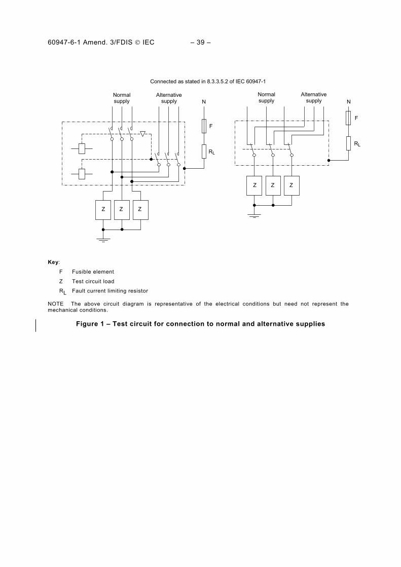
60947-6-1 Amend. 3/FDIS © IEC – 39 –
Normal supply
Alternative supply
F
RL
N
Z Z Z
Normal supply
Alternative supply
Connected as stated in 8.3.3.5.2 of IEC 60947-1
F
RL
Z Z Z
N
Key:
F Fusible element
Z Test circuit load
RL Fault current limiting resistor
NOTE The above circuit diagram is representative of the electrical conditions but need not represent the mechanical conditions.
Figure 1 – Test circuit for connection to normal and alternative supplies
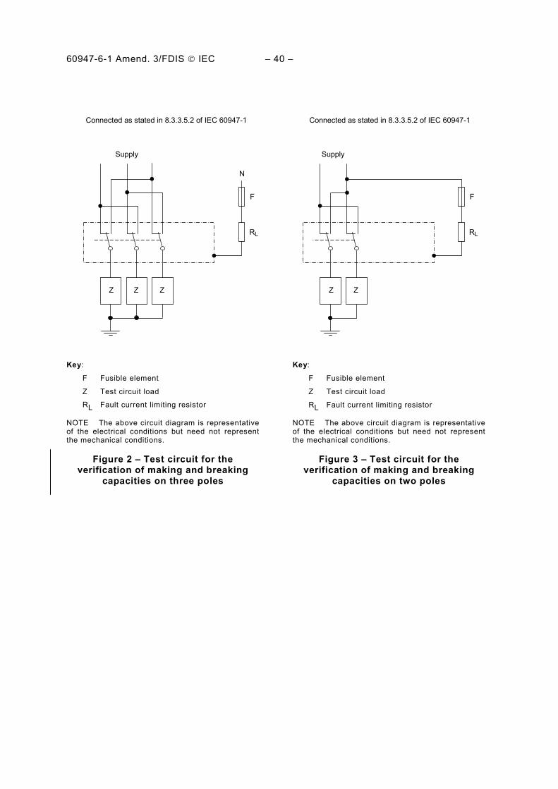
60947-6-1 Amend. 3/FDIS © IEC – 40 –
Connected as stated in 8.3.3.5.2 of IEC 60947-1
Supply
F
RL
N
Z Z Z
Supply
F
RL
Z Z
Connected as stated in 8.3.3.5.2 of IEC 60947-1
Key:
F Fusible element
Z Test circuit load
RL Fault current limiting resistor
Key:
F Fusible element
Z Test circuit load
RL Fault current limiting resistor
NOTE The above circuit diagram is representative of the electrical conditions but need not represent the mechanical conditions.
NOTE The above circuit diagram is representative of the electrical conditions but need not represent the mechanical conditions.
Figure 2 – Test circuit for the verification of making and breaking
capacities on three poles
Figure 3 – Test circuit for the verification of making and breaking
capacities on two poles

60947-6-1 Amend. 3/FDIS © IEC – 41 –
Annex A (normative)
Assignment of utilization categories based
on results of tests
A.1 An TSE which has been tested for a single utilization category or at any combination of parameters (such as maximum operational voltage and current, etc.) can be assigned other utilization categories without further testing provided the test currents, voltages, power factors or time constants, number of operating cycles, the on and off times and the test circuit for the assigned utilization categories are not more severe than those at which the TSE has been tested and the temperature rise has been verified at a current not less than the highest assigned rated operational current.
For example, when tested for utilization category AC-35A, an TSE may be assigned utilization category AC-31A, provided Ie for AC-31A is not higher than 2 x Ie for AC-35A at the same rated operational voltage.
A.2 DC-33A and DC-33B TSE are assumed to be capable of opening and closing loads other than that on which they were tested provided that:
– the voltage and current do not exceed the specified values of Ue and Ie;
– the energy J stored in the actual load is equal to or less than the energy Jc stored in the load with which it was tested.
The values of the energy stored in the test circuit are as follows:
Utilization category Stored energy Jc
DC-33A and B 0,005 x Ue x Ie
The value of the constant 0,005 is derived from: Jc = 1/2 LI2
where the time constant has been replaced by 2,5 x 10⁻³ s and where U = Ue and I = 4 Ie.
See Table 2 of this part of IEC 60947.
A.3 For derived TSE, Table A.1 gives equivalence with utilization categories covered under other IEC 60947 product standards.

60947-6-1 Amend. 3/FDIS © IEC – 42 –
Table A.1 – Equivalence between utilization categories used in some IEC 60947 product standards
Description as in IEC 60947-6-1
IEC 60947-6-1
IEC 60947-2
IEC 60947-3
IEC 60947-4-1
IEC 60947-4-2
d
IEC 60947-4-3
d
IEC 60947-6-2
AC-31A X AC-21A a AC-1 AC-41 Non-inductive or slightly inductive loads AC-31B X AC-21B a AC-1 AC-41
AC-32A X AC-22A AC-2 AC-2 AC-42 Switching of mixed resistive and inductive loads, including moderate overloads
AC-32B X AC-22B AC-2 AC-42
AC-33A AC-23A b AC-3 AC-3 AC-4 AC-43
AC-44 Motor loads or mixed loads including motors, resistive loads and up to 30 % incandescent lamp loads
AC-33B AC-23B b AC-3 AC-4 AC-43
AC-44
AC-35A AC-5a AC-45a Electric discharge lamp loads AC-35B AC-5a AC-45a
AC-36A AC-5b AC-45b Incandescent lamps
AC-36B AC-5b AC-45b
DC-31A DC-21A c DC-1 DC-41 Resistive loads
DC-31B DC-21B c DC-1 DC-41
DC-33A DC-23A c DC-3 DC-3 DC-43 Motor loads or mixed loads including motors DC-33B DC-23B c DC-3 DC-43
DC-36A DC-6 DC-46 Incandescent lamps
DC-36B DC-6 DC-46
X: covers corresponding IEC 60947-6-1 categories.
a Cos ϕ and number of operation differ with those of corresponding IEC 60947-6-1 categories. b Current and number of operation differ with those of corresponding IEC 60947-6-1 categories. c Number of operation differs with those of corresponding IEC 60947-6-1 categories. d Given for information only as TSE derived from products under these standards are not covered by this part of IEC 60947.

60947-6-1 Amend. 3/FDIS © IEC – 43 –
Annex B (informative)
Items subject to agreement between
manufacturer and user
NOTE For the purpose of this annex:
– "agreement" is used in a very wide sense,
– "user" includes testing stations.
Annex J of IEC 60947-1 applies, as far as covered by clauses and subclauses of this part of IEC 60947, with the following additions:
Clause or subclause number of this part of iEC 60947
Item
9.3.1
Tables 8, 9 and 10
To make all test sequences on one sample (if requested or agreed by the manufacturer)
Reduction of the time of cycles of operations for the tests of making and breaking capacity and for those of operational performance (manufacturer’s agreement)
___________

ISBN 2-8318-XXXX-X
ICS 29.120.40; 29.130.20
Typeset and printed by the IEC Central Office GENEVA, SWITZERLAND