Final draft ETSI EN 301 216 V1.2 · PDF fileETSI 3 Final draft ETSI EN 301 216 V1.2.1...
35
Final draft ETSI EN 301 216 V1.2.1 (2001-03) European Standard (Telecommunications series) Fixed Radio Systems; Point-to-point equipment; Plesiochronous Digital Hierarchy (PDH); Low and medium capacity and STM-0 digital radio system operating in the frequency bands in the range 3 GHz to 11 GHz
-
Upload
nguyenhuong -
Category
Documents
-
view
236 -
download
2
Transcript of Final draft ETSI EN 301 216 V1.2 · PDF fileETSI 3 Final draft ETSI EN 301 216 V1.2.1...
Final draft ETSI EN 301 216 V1.2.1 (2001-03)European Standard (Telecommunications series)
Fixed Radio Systems;Point-to-point equipment;
Plesiochronous Digital Hierarchy (PDH);Low and medium capacity and STM-0 digital
radio system operating in the frequency bandsin the range 3 GHz to 11 GHz

ETSI
Final draft ETSI EN 301 216 V1.2.1 (2001-03)2
ReferenceREN/TM-04111-02
KeywordsDRRS, PDH, SDH, STM, point-to-point,
transmission
ETSI
650 Route des LuciolesF-06921 Sophia Antipolis Cedex - FRANCE
Tel.: +33 4 92 94 42 00 Fax: +33 4 93 65 47 16
Siret N° 348 623 562 00017 - NAF 742 CAssociation à but non lucratif enregistrée à laSous-Préfecture de Grasse (06) N° 7803/88
Important notice
Individual copies of the present document can be downloaded from:http://www.etsi.org/
The present document may be made available in more than one electronic version or in print. In any case of existing orperceived difference in contents between such versions, the reference version is the Portable Document Format (PDF).
In case of dispute, the reference shall be the printing on ETSI printers of the PDF version kept on a specific networkdrive within ETSI Secretariat.
Users of the present document should be aware that the document may be subject to revision or change of status.Information on the current status of this and other ETSI documents is available at http://www.etsi.org/tb/status/
If you find errors in the present document, send your comment to:[email protected]
Copyright Notification
No part may be reproduced except as authorized by written permission.The copyright and the foregoing restriction extend to reproduction in all media.
© European Telecommunications Standards Institute 2001.All rights reserved.
ETSI
Final draft ETSI EN 301 216 V1.2.1 (2001-03)3
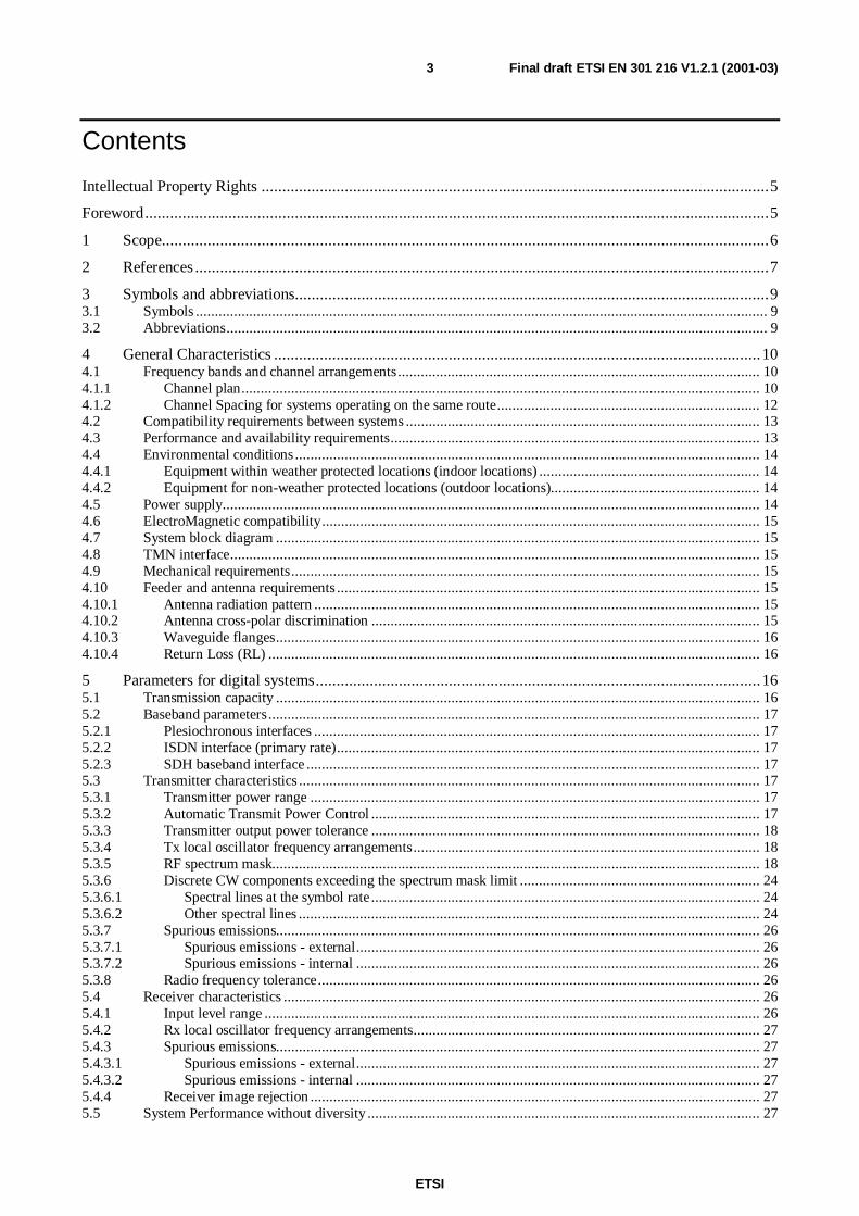
Contents
Intellectual Property Rights ..........................................................................................................................5
Foreword......................................................................................................................................................5
1 Scope..................................................................................................................................................6
2 References ..........................................................................................................................................7
3 Symbols and abbreviations..................................................................................................................93.1 Symbols ...................................................................................................................................................... 93.2 Abbreviations.............................................................................................................................................. 9
4 General Characteristics .....................................................................................................................104.1 Frequency bands and channel arrangements............................................................................................... 104.1.1 Channel plan........................................................................................................................................ 104.1.2 Channel Spacing for systems operating on the same route..................................................................... 124.2 Compatibility requirements between systems ............................................................................................. 134.3 Performance and availability requirements................................................................................................. 134.4 Environmental conditions .......................................................................................................................... 144.4.1 Equipment within weather protected locations (indoor locations) .......................................................... 144.4.2 Equipment for non-weather protected locations (outdoor locations)....................................................... 144.5 Power supply............................................................................................................................................. 144.6 ElectroMagnetic compatibility................................................................................................................... 154.7 System block diagram ............................................................................................................................... 154.8 TMN interface........................................................................................................................................... 154.9 Mechanical requirements........................................................................................................................... 154.10 Feeder and antenna requirements ............................................................................................................... 154.10.1 Antenna radiation pattern ..................................................................................................................... 154.10.2 Antenna cross-polar discrimination ...................................................................................................... 154.10.3 Waveguide flanges............................................................................................................................... 164.10.4 Return Loss (RL) ................................................................................................................................. 16
5 Parameters for digital systems...........................................................................................................165.1 Transmission capacity ............................................................................................................................... 165.2 Baseband parameters................................................................................................................................. 175.2.1 Plesiochronous interfaces ..................................................................................................................... 175.2.2 ISDN interface (primary rate)............................................................................................................... 175.2.3 SDH baseband interface ....................................................................................................................... 175.3 Transmitter characteristics ......................................................................................................................... 175.3.1 Transmitter power range ...................................................................................................................... 175.3.2 Automatic Transmit Power Control ...................................................................................................... 175.3.3 Transmitter output power tolerance ...................................................................................................... 185.3.4 Tx local oscillator frequency arrangements........................................................................................... 185.3.5 RF spectrum mask................................................................................................................................ 185.3.6 Discrete CW components exceeding the spectrum mask limit ............................................................... 245.3.6.1 Spectral lines at the symbol rate ...................................................................................................... 245.3.6.2 Other spectral lines ......................................................................................................................... 245.3.7 Spurious emissions............................................................................................................................... 265.3.7.1 Spurious emissions - external.......................................................................................................... 265.3.7.2 Spurious emissions - internal .......................................................................................................... 265.3.8 Radio frequency tolerance.................................................................................................................... 265.4 Receiver characteristics ............................................................................................................................. 265.4.1 Input level range .................................................................................................................................. 265.4.2 Rx local oscillator frequency arrangements........................................................................................... 275.4.3 Spurious emissions............................................................................................................................... 275.4.3.1 Spurious emissions - external.......................................................................................................... 275.4.3.2 Spurious emissions - internal .......................................................................................................... 275.4.4 Receiver image rejection ...................................................................................................................... 275.5 System Performance without diversity ....................................................................................................... 27

ETSI
Final draft ETSI EN 301 216 V1.2.1 (2001-03)4
5.5.1 BER as a function of receiver input signal level RSL ............................................................................ 275.5.2 Equipment maximum allowed number of errors.................................................................................... 285.5.3 Interference sensitivity ......................................................................................................................... 285.5.3.1 Co-channel external interference sensitivity .................................................................................... 295.5.3.2 Adjacent Channel interference sensitivity........................................................................................ 305.5.3.3 CW interference ............................................................................................................................. 305.5.3.4 Front-end non-linearity requirements (Two-tone CW Spurious interference).................................... 315.5.4 Distortion sensitivity............................................................................................................................ 315.6 System characteristics with diversity.......................................................................................................... 325.6.1 Differential delay compensation ........................................................................................................... 325.6.2 BER performance ................................................................................................................................ 325.6.3 Interference sensitivity ......................................................................................................................... 325.6.4 Distortion sensitivity............................................................................................................................ 32
Annex A (informative): Additional information ..............................................................................33
A.1 Antenna requirements .......................................................................................................................33A.1.1 Antenna radiation patterns ......................................................................................................................... 33A.1.2 Antenna cross-polar discrimination (XPD)................................................................................................. 33A.1.3 Feeder/antenna return loss ......................................................................................................................... 33
A.2 Automatic Transmit Power Control...................................................................................................33
A.3 Spectrum masks................................................................................................................................34
A.4 Lightning protection .........................................................................................................................34
A.5 Mechanical requirements ..................................................................................................................34
History .......................................................................................................................................................35

ETSI
Final draft ETSI EN 301 216 V1.2.1 (2001-03)5
Intellectual Property RightsIPRs essential or potentially essential to the present document may have been declared to ETSI. The informationpertaining to these essential IPRs, if any, is publicly available for ETSI members and non-members, and can befound in ETSI SR 000 314: "Intellectual Property Rights (IPRs); Essential, or potentially Essential, IPRs notified toETSI in respect of ETSI standards", which is available from the ETSI Secretariat. Latest updates are available on theETSI Web server (http://www.etsi.org/ipr).
Pursuant to the ETSI IPR Policy, no investigation, including IPR searches, has been carried out by ETSI. No guaranteecan be given as to the existence of other IPRs not referenced in ETSI SR 000 314 (or the updates on the ETSI Webserver) which are, or may be, or may become, essential to the present document.
ForewordThis European Standard (Telecommunications series) has been produced by ETSI Technical Committee Transmissionand Multiplexing (TM), and is now submitted for the ETSI standards One-step Approval Procedure.
The former title of the present document was: "Transmission and Multiplexing (TM); Digital Radio Relay Systems(DRRS); Plesiochronous Digital Hierarchy (PDH); Low and medium capacity and STM-0 DRRS operating in thefrequency bands in the range 3 GHz to 11 GHz".
Proposed national transposition dates
Date of latest announcement of this EN (doa): 3 months after ETSI publication
Date of latest publication of new National Standardor endorsement of this EN (dop/e): 6 months after doa
Date of withdrawal of any conflicting National Standard (dow): 6 months after doa

ETSI
Final draft ETSI EN 301 216 V1.2.1 (2001-03)6
1 ScopeThe present document specifies the minimum performance parameters for low and medium capacity terrestrial fixedservice digital radiocommunications equipment operating in the frequency bands between around 3 GHz and 11 GHzbut nevertheless such systems should provide the efficient use of the spectrum under any conditions.
The present document covers equipment intended to be used at nominal data rates for PDH systems between 2 Mbit/sand 2 × 34 Mbit/s and for SDH systems transmitting STM-0 signals with a VC3 payload capacity.
Consideration has to be given to special requirements of the local and access network especially different networkstructures with high density nodes.
The systems considered are envisaged to operate in these networks having regard for existing hop lengths which mainlydepend on the intended frequency band, the performance objectives set by relevant ITU-R Recommendations ornational network operators requirements and existing propagation characteristics. The hop lengths are considered to beup to about 100 km in the frequency band 3 GHz and 60 km in the frequency band 11 GHz taking into account diversitytechniques.
Typical applications include:
a) point-to-point links in local, regional and national networks;
b) mobile base station connections;
c) business networks connections;
d) customer access links.
The parameters to be specified fall into two categories:
a) Those that are required to provide compatibility between RF channels from different sources of equipment onthe same route, connected either to:
- separate antennas; or to
- separate polarization of the same antenna.
b) Parameters defining the transmission quality of the proposed system.
The standardization deals with RF and baseband characteristics relevant to low and medium capacity PDH andSTM-0 SDH transmission. Spurious emissions requirements are also included in the present document. EMCrequirements are covered in EN 300 385 [23]. Antenna/feeder system requirements are covered in ETS 300 833 [1].
As the maximum transmission rate in a given bandwidth depends on systems spectral efficiency, different Classes aredefined:
Class 1: Equipment based on performances of a typical 4-states modulation scheme.
Class 2: Equipment based on performances of a typical 16-states modulation scheme.
Class 3: Equipment based on performances of a typical 32 or 64-states modulation scheme.
Safety is not considered in the present document.

ETSI
Final draft ETSI EN 301 216 V1.2.1 (2001-03)7
2 ReferencesThe following documents contain provisions which, through reference in this text, constitute provisions of the presentdocument.
• References are either specific (identified by date of publication, edition number, version number, etc.) ornon-specific.
• For a specific reference, subsequent revisions do not apply.
• For a non-specific reference, subsequent revisions do apply.
[1] ETSI ETS 300 833: "Fixed Radio Systems; Point to Point Antennas; Antennas for point-to-pointfixed radio systems operating in the frequency band 3 GHz to 60 GHz".
[2] CEPT/ERC/Recommendation 14-03: "Harmonised radio frequency channel arrangements for lowand medium capacity systems in the band 3400 MHz to 3600 MHz".
[3] CEPT/ERC/Recommendation 12-08: "Harmonised radio frequency channel arrangements andblock allocations for medium and high capacity systems in the band 3600 MHz to 4200 MHz".
[4] ITU-R Recommendation F.383-6: "Radio-frequency channel arrangements for high capacityradio-relay systems operating in the lower 6 GHz band".
[5] ITU-R Recommendation F.384-7: "Radio-frequency channel arrangements for medium and highcapacity analogue or digital radio-relay systems operating in the upper 6 GHz band".
[6] ITU-R Recommendation F.385-6: "Radio-frequency channel arrangements for radio-relay systemsoperating in the 7 GHz band".
[7] ITU-R Recommendation F.386-6: "Radio-frequency channel arrangements for medium and highcapacity analogue or digital radio-relay systems operating in the 8 GHz band".
[8] ITU-R Recommendation F.746-4: "Radio-frequency channel arrangements for radio-relaysystems".
[9] ITU-R Recommendation F.747: "Radio-frequency channel arrangements for radio-relay systemsoperating in the 10 GHz band".
[10] CEPT/ERC/Recommendation 12-05: "Harmonised radio frequency channel arrangements fordigital terrestrial fixed systems operating in the band 10.0 - 10.68 GHz".
[11] ITU-R Recommendation F.635-5: "Radio-frequency channel arrangements based on ahomogeneous pattern for radio-relay systems operating in the 4 GHz band".
[12] ITU-R Recommendation F.382-7: "Radio-frequency channel arrangements for radio-relay systemsoperating in the 2 and 4 GHz bands".
[13] ITU-R Recommendation F.1092-1: "Error performance objectives for constant bit rate digital pathat or above the primary rate carried by digital radio-relay systems which may form part of theinternational portion of a 27 500 km hypothetical reference path".
[14] ITU-R Recommendation F.1189-1: "Error performance objectives for constant bit rate digitalpaths at or above the primary rate carried by digital radio-relay systems which may form part or allof the national portion of a 27 500 km hypothetical reference path".
[15] ITU-R Recommendation F.557-4: "Availability objective for radio-relay systems over ahypothetical reference circuit and a hypothetical reference digital path".
[16] ITU-T Recommendation G.826: "Error performance parameters and objectives for international,constant bit rate digital paths at or above the primary rate".
[17] ITU-T Recommendation G.827: "Availability parameters and objectives for path elements ofinternational constant bit-rate digital paths at or above the primary rate".
ETSI
Final draft ETSI EN 301 216 V1.2.1 (2001-03)8
[18] ITU-R Recommendation F.752-1: "Diversity techniques for radio-relay systems".
[19] ITU-R Recommendation F.1093-1: "Effects of multipath propagation on the design and operationof line-of-sight digital radio-relay systems".
[20] ITU-R Recommendation F.1101: "Characteristics of digital radio-relay systems below about17 GHz".
[21] ETSI ETS 300 019 (Parts 1 and 2): "Equipment Engineering (EE); Environmental conditions andenvironmental tests for telecommunications equipment; Part 1: Classification of environmentalconditions; Part 2: Specification of environmental tests".
[22] ETSI ETS 300 132 (Parts 1 and 2): "Equipment Engineering (EE); Power supply interface at theinput to telecommunications equipment; Part 1: Operated by alternating current (ac) derived fromdirect current (dc) sources; Part 2: Operated by direct current (dc)".
[23] ETSI EN 300 385: "Electromagnetic compatibility and Radio spectrum Matters (ERM);ElectroMagnetic Compatibility (EMC) standard for fixed radio links and ancillary equipment".
[24] ITU-T Recommendation G.773: "Protocol suites for Q-interfaces for management of transmissionsystems".
[25] IEC 60154 (all parts): "Flanges for waveguides".
[26] ITU-T Recommendation G.703: "Physical/electrical characteristics of hierarchical digitalinterfaces".
[27] ITU-T Recommendation G.704: "Synchronous frame structures used at 1544, 6312, 2048, 8488and 44 736 kbit/s hierarchical levels".
[28] ITU-T Recommendation I.412: "ISDN user-network interfaces - Interface structures and accesscapabilities".
[29] ETSI ETS 300 233: "Integrated Services Digital Network (ISDN); Access digital section for ISDNprimary rate".
[30] ITU-T Recommendation G.707: "Network node interface for the synchronous digital hierarchy(SDH)".
[31] Void.
[32] Void.
[33] ITU-T Recommendation G.783: "Characteristics of synchronous digital hierarchy (SDH)equipment functional blocks".
[34] ITU-T Recommendation G.784: "Synchronous digital hierarchy (SDH) management".
[35] ITU-T Recommendation G.957: "Optical interfaces for equipments and systems relating to thesynchronous digital hierarchy".
[36] ITU-R Recommendation F.750-3: "Architectures and functional aspects of radio-relay systems forsynchronous digital hierarchy (SDH)-based networks."
[37] ITU-R Recommendation SM.329-7: "Spurious emissions".
[38] ITU-R Recommendation F.1191-1: "Bandwidths and unwanted emissions of digital radio-relaysystems"
[39] ETSI ETS 300 119: "Equipment Engineering (EE); European telecommunication standard forequipment practice".
[40] ETSI TR 101 035: "Transmission and Multiplexing (TM); Synchronous Digital Hierarchy (SDH)aspects regarding Digital Radio Relay Systems (DRRS)".

ETSI
Final draft ETSI EN 301 216 V1.2.1 (2001-03)9
[41] ETSI TR 101 036-1: "Fixed Radio Systems; Point-to-point equipment; Generic wordings forstandards on digital radio systems characteristics; Part 1: General aspects and point-to-pointequipment parameters".
[42] CEPT/ERC Recommendation 74-01: "Spurious emissions".
3 Symbols and abbreviations
3.1 SymbolsFor the purposes of the present document, the following symbols apply:
dB decibeldBm decibel relative to 1 mWHz hertzid idemGHz gigahertzkbit/s kilobits per secondkHz kilohertzkm kilometerMbit/s megabits per secondMHz megahertzns nanosecondppm part per million
3.2 AbbreviationsFor the purposes of the present document, the following abbreviations apply:
ACDP Adjacent Channel Dual PolarizedATPC Automatic Transmit Power ControlBBER Background Bit Error RateBER Bit Error RatioC/I Carrier to Interference ratioCMI Coded Marked InvertedCS Channel SpacingCSmin minimum practical channel separation (for a given radio-frequency channel arrangement)CW Continuous WaveEMC ElectroMagnetic CompatibilityERC European Radio CommitteeFc Cut-off FrequencyFs Symbol RateIF Intermediate FrequencyISDN Integrated Services Digital NetworkLO Local OscillatorNFD Net Filter DiscriminationPDH Plesiochronous Digital HierarchyPSD Power Spectral DensityPSTN Public Switched Telecommunication NetworkRF Radio FrequencyRSL Receive Signal LevelRx ReceiverSDH Synchronous Digital HierarchySOH Section OverHeadSTM Synchronous Transfer ModuleTMN Telecommunications Management NetworkTx TransmitterVC Virtual Container

ETSI
Final draft ETSI EN 301 216 V1.2.1 (2001-03)10
W/U Wanted to Unwanted ratioXPD Cross Polar Discrimination
4 General Characteristics
4.1 Frequency bands and channel arrangements
4.1.1 Channel plan
The equipment should operate on one or more of the frequency ranges defined below.
The frequency ranges are:
- 3,410 GHz to 3,600 GHz;
- 3,600 GHz to 4,200 GHz;
- 5,925 GHz to 6,425 GHz;
- 6,425 GHz to 7,100 GHz;
- 7,110 GHz to 7,900 GHz;
- 7,725 GHz to 8,500 GHz;
- 10,000 GHz to 10,680 GHz.
The channel plan should be in accordance with the CEPT ERC or ITU-R Recommendations listed in table 1.
Table 1: Relevant CEPT ERC and ITU-R Recommendations
CEPT ERC or ITU-R Recommendation Band Frequency rangeERC/REC 14-03 [2] 3,5 GHz 3,410 GHz to 3,600 GHzERC/REC 12-08 [3] Annex A 4 GHz 3,600 GHz to 4,200 GHzERC/REC 12-08 [3] Annex B Part 2 id 3,600 GHz to 3,800 GHzERC/REC 12-08 [3] Annex B Part 1 id 3,800 GHz to 4,200 GHzITU-R Recommendation F.383-6 [4] L6 GHz 5,925 GHz to 6,425 GHzITU-R Recommendation F.384-7 [5] U6 GHz 6,425 GHz to 7,100 GHzITU-R Recommendation F.385-6 [6] 7 GHz 7,125 GHz to 7,425 GHzid id 7,425 GHz to 7,725 GHzid id 7,250 GHz to 7,550 GHzid id 7,550 GHz to 7,850 GHzITU-R Recommendation F.385-6 [6] Annex 1 id 7,425 GHz to 7,725 GHzITU-R Recommendation F.385-6 [6] Annex 3 id 7,110 GHz to 7,750 GHzITU-R Recommendation F.385-6 [6] Annex 4 id 7,425 GHz to 7,900 GHzITU-R Recommendation F.386-6 [7] 8 GHz 8,200 GHz to 8,500 GHzITU-R Recommendation F.386-6 [7] Annex 1 id 7,725 GHz to 8,275 GHzITU-R Recommendation F.386-6 [7] Annex 3 id 8,275 GHz to 8,500 GHzITU-R Recommendation F.386-6 [7] Annex 4 (seenote)
id 7,900 GHz to 8,400 GHz
ITU-R Recommendation F.746-4 [8] Annex 4 10 GHz 10,300 GHz to 10,680 GHzITU-R Recommendation F.747 [9] 10 GHz 10,500 GHz to 10,680 GHzERC/REC 12-05 [10] 10 GHz 10,150 GHz to 10,300 GHz paired
with 10,500 GHz to 10,650 GHz

ETSI
Final draft ETSI EN 301 216 V1.2.1 (2001-03)11
Description of relevant characteristics is provided by tables 2a and 2b.
Table 2a: Channel plans characteristics/PDH applications
Frequency band Band limits Channel spacing Transmit/receivespacing
ERC/REC 14-03 [2] 3,410 GHz to 3,600 GHz 1,75/3,5/7/14 MHz 100 MHz or50 MHz
ERC/REC 12-08 [3]Annex A Part 1Annex A Part 2Annex B Part 1Annex B Part 2
3,6 GHz to 4,2 GHz based on ITU-R Rec. F.635-5 [11]3,6 GHz to 4,2 GHz based on ITU-R Rec. F.635-5 [11]3,8 GHz to 4,2 GHz based on ITU-R Rec. F.382-7 [12]
3,6 GHz to 3,8 GHz divided into 0,25 MHz slots
20 MHz15/30 MHz
14,5/29 MHz1,75/3,5/7/
14 MHz(basic raster0,25 MHz)
320 MHz320 MHz213 MHz
100 or 50 MHz
ITU-R Rec. F.383-6[4]
5,925 GHz to 6,425 GHz 29,65 MHz 252,04 MHz
7 GHzITU-R Rec. F.385-6[6]
7,425 GHz to 7,725 GHz7,125 GHz to 7,425 GHz7,250 GHz to 7,550 GHz7,550 GHz to 7,850 GHz
7/14/28 MHz 161 MHz
ITU-R Rec. F.385-6[6]Annex 1
7,425 GHz to 7,725 GHz 28 MHz 154 MHz
ITU-R Rec. F.385-6[6]Annex 3
7,110 GHz to 7,750 MHz 28 MHz 196 MHz
ITU-R Rec. F.385-6[6]Annex 4
7,425 GHz to 7,900 GHz 7/14/28 MHz 245 MHz
ITU-R Rec. F.386-6[7]
8,200 GHz to 8,500 GHz 11,662 MHz 151,614 MHz
ITU-R. Rec. F.386-6[7]Annex 1
7,725 GHz to 8,275 GHz 29,65 GHz 311,32 MHz
ITU-R Rec. F.386-6[7]Annex 3
8,275 GHz to 8,500 GHz
id
14/28 MHz
7/14/28 MHz
119 MHz
126 MHzITU-R Rec. F.386-6[7]Annex 4
7,900 GHz to 8,400 GHz 7/14/28 MHz 266 MHz
ITU-R Rec. F.747 [9]ITU-R Rec. F.747 [9]Annex 1
10,5 GHz to 10,68 GHz 3,5/7/14 MHz(homogeneous
pattern 3,5 MHz)
91 MHz
ERC/REC 12-05 [10] 10,15 GHz to 10,30 GHz paired with10,5 GHz to 10,65 GHz
3,5/7/14/28 MHz(basic raster
0,5 MHz)
350 MHz

ETSI
Final draft ETSI EN 301 216 V1.2.1 (2001-03)12
Table 2b: Channel plans characteristics/STM-0 applications
Frequency band Band limits Channelspacing
Transmit/receive spacing
ERC/REC 14-03 [2] 3,410 GHz to 3,600 GHz 14 MHz 100 MHz or50 MHz
ERC/REC 12-08 [3] 3,6 GHz to 4,2 GHzAnnex A Part1 3,6 GHz to 4,2 GHz based on ITU-R Rec F.635-5 [11] 20 MHz 320 MHzAnnex A Part 2 3,6 GHz to 4,2 GHz based on ITU-R Rec F.635-5 [11] 15/30 MHz 320 MHzAnnex B Part 1 3,8 GHz to 4,2 GHz based on ITU-R Rec 382-7 [12] 14,5/29 MHz 213 MHzAnnex B Part 2 3,6 GHz to 3,8 GHz divided into 0,25 MHz slots 14 MHz (basic
raster 0,25 MHz)100 MHz or
50 MHzL6 GHzITU-R Rec. F.383-6 [4]
5,925 GHz to 6,425 GHz 29,65 MHz 252,04 MHz
U6 GHzITU-R Rec. F.384-7 [5]
6,425 GHz to 7,100 GHz 20 MHz 340 MHz
7 GHzITU-R Rec. F.385-6 [6]
7,125 GHz to 7,425 GHz7,425 GHz to 7,725 GHz7,250 GHz to 7,550 GHz7,550 GHz to 7,850 GHz
14 MHz, 21 MHz,28 MHz
161 MHz
7 GHzITU-R Rec. F.385-6 [6]Annex 1
7,425 GHz to 7,725 GHz 28 MHz 154 MHz
7 GHzITU-R Rec. F.385-6 [6]Annex 3
7,110 GHz to 7,780 MHz 28 MHz 196 MHz
7 GHzITU-R Rec. F.385-6 [6][6]Annex 4
7,425 GHz to 7,900 GHz 14/28 MHz 245 MHz
8 GHzITU-R Rec. F.386-6 [7]
8,200 GHz to 8,500 GHz 2 × 11,662 MHz 151,614 MHz
8 GHzITU-R Rec. F.386-6 [7]Annex 1
7,725 GHz to 8,275 GHz 29,65 MHz 311,32 MHz
8 GHzITU-R Rec. F.386-6 [7]Annex 3
8,275 GHz to 8,500 GHz
id
14/28 MHz
14/21/28 MHz
119 MHz
126 MHz8 GHzITU-R Rec. F.386-6 [7]Annex 4
7,900 GHz to 8,400 GHz 14/28 MHz 266 MHz
10 GHzERC/REC 12-05 [10]
10,15 GHz to 10,30 GHz paired with10,5 GHz to 10,65 GHz
14/28 MHz(basic raster
0,5 MHz)
350 MHz
10 GHzITU-R Rec. F.746-4 [8]Annex 4
10,300 GHz to 10,680 GHz 20 MHz
4.1.2 Channel Spacing for systems operating on the same route
Multiple channel operation via branching networks is a system consideration and is outside the scope of the presentdocument.
The systems in the present document are designed to operate on the same route using the combinations of co-polar orcross-polar channel spacings and nominal system bit rate given in tables 3a and 3b (for the precise payload bit rates,see clause 5.1). In practice, when common antenna operation is envisaged, adjacent channels may be connected to adifferent polarization of the same antenna.

ETSI
Final draft ETSI EN 301 216 V1.2.1 (2001-03)13
Table 3a: Channel spacing for particular PDH bit rates
Co-polar spacing Cross-polar
spacingNominal
Payload BitRate Mbit/s
2 Mbit/s 2 ×××× 2Mbit/s
8 Mbit/s 2 ×××× 8Mbit/s
34 Mbit/s 2 ×××× 34Mbit/s
2 ×××× 34Mbit/s
Channel Class 1 1,75 MHz 3,5 MHz 7 MHz/11,662MHz
14 MHz/14,5 MHz/15 MHz
28 MHz/29 MHZ/
29,65 MHz/30 MHz
--- ---
Spacing Class 2 ---- 1,75 MHz 3,5 MHz 7 MHz 14 MHz/14,5 MHz/15 MHz
28 MHz/29 MHz/
29,65 MHz/30 MHz
---
Class 3 ---- --- --- --- --- 14 MHz/14,5 MHz/15 MHz
14 MHz/14,5 MHz/15 MHz(note)
NOTE: Variations of Class 3 equipment exist designed to operate cross-polarization in adjacent channels(ACDP systems). In this case the co-polar CS would become 28 MHz, 29 MHz or 30 MHz.
Table 3b: Channel spacing for STM-0 bit rate
NominalPayloadbit rate(Mbit/s)
51 Mbit/s
Channel Class 2 --- 20 MHz 21 MHz 2 × 11,662MHz
28 MHz/29 MHz/
29,65 MHz/30 MHz
Spacing Class 3 14 MHz/14,5 MHz/15 MHz
--- --- --- ---
4.2 Compatibility requirements between systemsThere should be no requirement to operate transmitting equipment from one manufacturer with receiving equipmentfrom another.
Different manufacturer equipment may be used on different polarization of the same antenna but there should be norequirement to multiplex different manufacturer equipment on the same polarization of the same antenna.
4.3 Performance and availability requirementsEquipment should be designed in order to meet network performance and availability requirements foreseen byITU-R Recommendations F.1092-1 [13], F. 1189-1 [14] and F.557-4 [15] following the criteria defined inITU-T Recommendations G.826 [16] and G.827 [17] for international or national portion of the digital path.
The implication of the link design on the performance is recognized and the general design criteria reported inITU-R Recommendations F.752-1 [18], F.1093-1 [19], F.1101 [20], F.1092-1 [13] and F.1189-1 [14] are to be applied.

ETSI
Final draft ETSI EN 301 216 V1.2.1 (2001-03)14
4.4 Environmental conditionsBoth indoor and partially outdoor installations are considered.
The equipment should be required to meet the environmental conditions set out in ETS 300 019 [21] which definesweather protected and non-weather protected locations, classes and test severity.
The manufacturer should state which class the equipment is designed to withstand.
4.4.1 Equipment within weather protected locations (indoor locations)
Equipment intended for operation within temperature controlled locations or partially temperature controlled locationsshould meet the requirements of ETS 300 019 [21] classes 3.1 and 3.2 respectively.
Optionally, the more stringent requirements of ETS 300 019 [21] classes 3.3 (non-temperature controlled locations), 3.4(sites with heat trap) and 3.5 (sheltered locations) may be applied.
4.4.2 Equipment for non-weather protected locations (outdoor locations)
Equipment intended for operation within non-weather protected locations should meet the requirements ofETS 300 019 [21], class 4.1 or 4.1E.
Class 4.1 applies to many European countries and class 4.1E applies to all European countries.
4.5 Power supplyThe power supply interface should be in accordance with the characteristics of one or more of the secondary voltagesforeseen in Parts 1 and 2 of ETS 300 132 [22].
NOTE: Some applications may require secondary voltages that are not covered by ETS 300 132 [22].
For DC systems, the positive pole of the voltage supply should be earthed at the source.

ETSI
Final draft ETSI EN 301 216 V1.2.1 (2001-03)15
4.6 ElectroMagnetic compatibilityEquipment should operate under the conditions specified in EN 300 385 [23].
4.7 System block diagram
TRANSMITRF FILTER
RECEIVERF FILTER
RECEIVERF FILTER
DEMODULATOR
DEMODULATOR
MODULATOR TRANSMITTER
RECEIVER
RECEIVER
BRANCHING(see note 1)
BRANCHING
(see note 1)
BRANCHING
(see note 1)FEEDER
FEEDER
FEEDER
DIVERSITY RECEIVER PATH
MAIN RECEIVER PATH
Z' E' A' B' C' D'
ED AD BD CD DD
(see note 2) (see note 2)
Z E A B C D
NOTE 1: NO FILTERING INCLUDED.NOTE 2: ALTERNATIVE CONNECTION AT RF, IF OR BASEBAND.NOTE 3: For the purpose of defining the measurement points, the branching network does not include a hybrid.NOTE 4: The points shown above are reference points only; points C and C', D and D' in general coincide.NOTE 5: Points B and C, B' and C' may coincide when simple duplexer is used.NOTE 6: Diversity is an optional feature.
Figure 1: System Block Diagram
4.8 TMN interfaceTMN interface, if any, should be in accordance with ITU-T Recommendation G.773 [24].
NOTE: The standardization of TMN interface functionalities is under responsibility and development inETSI TC TMN (formerly in TM2), and will be applicable to the radio relay systems considered in thepresent document.
4.9 Mechanical requirementsSee clause A.5.
4.10 Feeder and antenna requirements
4.10.1 Antenna radiation pattern
See clause A.1.
4.10.2 Antenna cross-polar discrimination
See clause A.1.
ETSI
Final draft ETSI EN 301 216 V1.2.1 (2001-03)16
4.10.3 Waveguide flanges
If a waveguide flange is used at point C/C', the following types should all be used in accordance with IEC 60154 [25].
Table 4: RF Waveguide Interfaces
Frequency band Waveguide flange3,5 GHz UDR/UBR/PBR/CBR 32
4 GHz UDR/UBR/PBR/CBR 40U6 GHz UDR/UBR/PBR/CBR 707 GHz UDR/PDR/CDR 70 or 84
UBR/PBR/CBR 70 or 848 GHz UDR/PDR/CDR 84
UBR/PBR/CBR 8410,5 GHz UDR/PDR/CDR 100 or 120
UBR/PBR/CBR 100 or 120
4.10.4 Return Loss (RL)
The minimum return loss of the branching system should be 20 dB for Class 3 systems, 15 dB for Class 2 systems and12 dB for Class 1 systems. The measurement should be referred to point C/C' towards the radio equipment and across afrequency band greater than or equal to 0,7 times the maximum aggregate symbol rate.
Equipment according to the present document may also have system configuration with integral antennas or verysimilar technical solutions, without long feeder connections; return loss is not considered as an essential requirement.
When antenna is an integral part of the system there shall be no requirement.
NOTE: For indoor systems, a feeder + antenna return loss equal or better than 20 dB is assumed. If thisperformance is not achieved, values better than the above return loss figures may be required.
For feeder/antenna RL information, see clause A.1.
5 Parameters for digital systems
5.1 Transmission capacityFor sake of simplicity in the present document the considered nominal capacities will be simply referred to as 2 Mbit/s,2 × 2 Mbit/s, 8 Mbit/s, 2 × 8 Mbit/s, 34 Mbit/s, 2 × 34 Mbit/s and 51 Mbit/s (STM-0), these capacities will appear intables 3a, 3b, 8, 10a, 10b, 11 and in the titles of figures 2a to 2e.
However, the actual payload Bit Rate(s) considered should be 2,048 Mbit/s, 8,448 Mbit/s, 34,368 Mbit/s and STM-0 orany combinations of n × 2,048 Mbit/s (e.g. with n in the range 1 to 32) and n × 8,448 Mbit/s (e.g. with n in the range1 to 8).
Moreover medium capacity systems sometimes offer the option for one additional 2,048 Mbit/s way-side traffic built inthe radio frame complementary overhead; if this additional capacity will have the same transmission quality andequivalent TMN functionality of the standard payload rate, it should be considered among payload (e.g. resulting, in34 Mbit/s and STM-0 systems, in a transmission capacity of 17 × 2,048 Mbit/s or 22 × 2,048 Mbit/s respectively).
For example the relevant requirements, for the following n × 2,048 Mbit/s, can be found:
- for 4 × 2 Mbit/s in the rows related to 8 Mbit/s;
- for 8 × 2 Mbit/s (9 × 2 Mbit/s if applicable) in the rows related to 2 × 8 Mbit/s;
- for 16 × 2 Mbit/s (17 × 2 Mbit/s if applicable) in the rows related to 34 Mbit/s;
- for 21 × 2 Mbit/s (22 × 2 Mbit/s if applicable) in the rows related to 51 Mbit/s.

ETSI
Final draft ETSI EN 301 216 V1.2.1 (2001-03)17
5.2 Baseband parameters
5.2.1 Plesiochronous interfaces
Plesiochronous interfaces at 2 Mbit/s, 8 Mbit/s and 34 Mbit/s should comply with ITU-T Recommendation G.703 [26].Parameters for service channels and wayside traffic channels are outside the scope of the present document.
5.2.2 ISDN interface (primary rate)
The transmission of 2 Mbit/s signals using the structure and functions of ISDN primary multiplex signals is to be inaccordance with ITU-T Recommendations G.703 [26], G.704 [27], I.412 [28] and ETS 300 233 [29].
5.2.3 SDH baseband interface
The SDH baseband interfaces are in accordance with ITU-T Recommendations G.703 [26], G.707 [30], G.783 [33],G.784 [34] and G.957 [35] (with possible simplifications under study in ETSI TM3 and TM4) and ITU-RRecommendation F.750-3 [36].
Two STM-1 interfaces should be possible:
- CMI electrical (ITU-T Recommendation G.703 [26]);
- Optical (ITU-T Recommendation G.957 [35]).
The use of reserved bytes contained in the SOH, and their termination should be in accordance withITU-R Recommendation F.750-3 [36]. Further details on the possible use of the SOH bytes reserved for futureinternational standardization are given in TR 101 035 [40].
5.3 Transmitter characteristicsThe specified transmitter characteristics should be met with the appropriate baseband signals applied at reference pointZ' of figure 1.
5.3.1 Transmitter power range
The maximum value of output power at reference point B' (for equipment with multichannel branching system) or C'(for equipment with simple duplexer) of the system block diagram (figure 1) should not exceed +40 dBm under anyconditions. If for proper operation of the system, a lower transmitter output power is required, then an internal orexternal means of adjustment should be provided.
The maximum nominal value should be declared by the manufacturer.
5.3.2 Automatic Transmit Power Control
ATPC is an optional feature.
If implemented, the ATPC range should not be less than 10 dB.
NOTE: For hop lengths of more than about 35 km an ATPC device with a range of more than 20 dB may berequired for use on the same polarization on different antennas on the same route.
Equipment with ATPC will be subject to Manufacturer declaration of ATPC range and related tolerances.
Testing should be carried out with output power level corresponding to:
- ATPC set manually to a fixed value for system performance (see clauses 5.5 and 5.6);
- ATPC set at maximum provided power for Tx performance (see clause 5.3).
Further information on ATPC is given in clause A.2.
ETSI
Final draft ETSI EN 301 216 V1.2.1 (2001-03)18
5.3.3 Transmitter output power tolerance
The tolerance of the nominal output power should be within:
- nominal output power ±2 dB for systems operating within non-weather protected locations;
- nominal output power ±1 dB for systems operating within weather protected locations.
5.3.4 Tx local oscillator frequency arrangements
There should be no requirement on transmitter LO frequency arrangement.
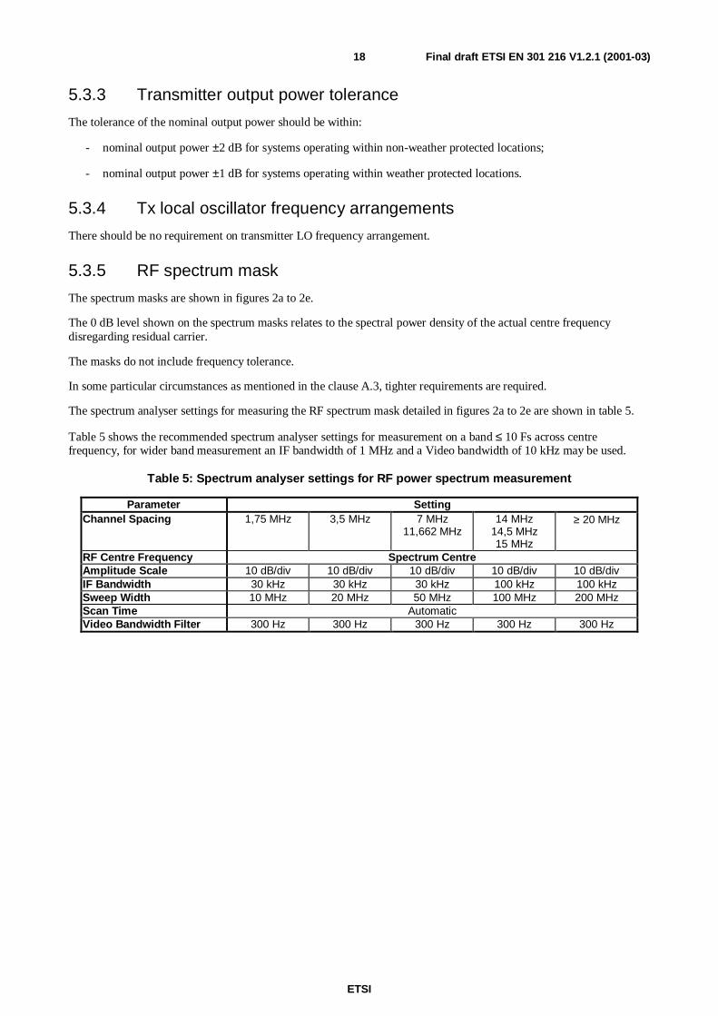
5.3.5 RF spectrum mask
The spectrum masks are shown in figures 2a to 2e.
The 0 dB level shown on the spectrum masks relates to the spectral power density of the actual centre frequencydisregarding residual carrier.
The masks do not include frequency tolerance.
In some particular circumstances as mentioned in the clause A.3, tighter requirements are required.
The spectrum analyser settings for measuring the RF spectrum mask detailed in figures 2a to 2e are shown in table 5.
Table 5 shows the recommended spectrum analyser settings for measurement on a band ≤ 10 Fs across centrefrequency, for wider band measurement an IF bandwidth of 1 MHz and a Video bandwidth of 10 kHz may be used.
Table 5: Spectrum analyser settings for RF power spectrum measurement
Parameter SettingChannel Spacing 1,75 MHz 3,5 MHz 7 MHz
11,662 MHz14 MHz
14,5 MHz15 MHz
≥ 20 MHz
RF Centre Frequency Spectrum CentreAmplitude Scale 10 dB/div 10 dB/div 10 dB/div 10 dB/div 10 dB/divIF Bandwidth 30 kHz 30 kHz 30 kHz 100 kHz 100 kHzSweep Width 10 MHz 20 MHz 50 MHz 100 MHz 200 MHzScan Time AutomaticVideo Bandwidth Filter 300 Hz 300 Hz 300 Hz 300 Hz 300 Hz

ETSI
Final draft ETSI EN 301 216 V1.2.1 (2001-03)19
Class 1 systems
Class 2 systems
Transmitter
Relative
Power (dB)
+10
-10
-20
-23
-30
-32
-37
-40
-45
-50
-55
-60
f0 fa fb fc fd fe
Frequency from actual carrier frequency
f0 = Actual Transmitter Carrier Frequency.
NOTE: These masks refer to actual centre frequency and do not include an allowance for frequency stabilityincluding ageing.
Figure 2a: Limits of power spectral density for 2 to 34 Mbit/s Class 1or 2 ×××× 2 to 2 ×××× 34 Mbit/s Class 2 system
ETSI
Final draft ETSI EN 301 216 V1.2.1 (2001-03)20
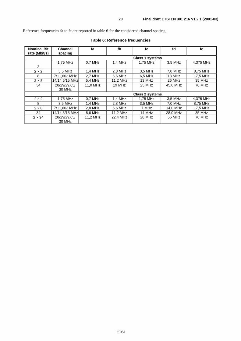
Reference frequencies fa to fe are reported in table 6 for the considered channel spacing.
Table 6: Reference frequencies
Nominal Bitrate (Mbit/s)
Channelspacing
fa fb fc fd fe
Class 1 systems
21,75 MHz 0,7 MHz 1,4 MHz 1,75 MHz 3,5 MHz 4,375 MHz
2 × 2 3,5 MHz 1,4 MHz 2,8 MHz 3,5 MHz 7,0 MHz 8,75 MHz8 7/11,662 MHz 2,7 MHz 5,6 MHz 6,5 MHz 13 MHz 17,5 MHz
2 × 8 14/14,5/15 MHz 5,4 MHz 11,2 MHz 13 MHz 26 MHz 35 MHz34 28/29/29,65/
30 MHz11,0 MHz 19 MHz 25 MHz 45,0 MHz 70 MHz
Class 2 systems2 × 2 1,75 MHz 0,7 MHz 1,4 MHz 1,75 MHz 3,5 MHz 4,375 MHz
8 3,5 MHz 1,4 MHz 2,8 MHz 3,5 MHz 7,0 MHz 8,75 MHz2 × 8 7/11,662 MHz 2,8 MHz 5,6 MHz 7 MHz 14,0 MHz 17,5 MHz34 14/14,5/15 MHz 5,6 MHz 11,2 MHz 14 MHz 28,0 MHz 35 MHz
2 × 34 28/29/29,65/30 MHz
11,2 MHz 22,4 MHz 28 MHz 56 MHz 70 MHz

ETSI
Final draft ETSI EN 301 216 V1.2.1 (2001-03)21
10
0
-10
-20
-30
-40
-50
-60
-70
-80
0 5
f0 f110
f2 f315 20 25 30
f435
f5
2,5 CS
NOTE 1: Frequency offset from the actual centre frequency (MHz).
Table of corner points
Frequency (MHz) Relative PSD(dB)
f0 7,5 MHz +1f1 9,5 MHz -10f2 12,5 MHz -35f3 15 MHz -40f4 30 MHz -55f5 2,5 × CS -55
NOTE 2: The masks refer to actual centre frequency and do not include an allowance for frequency stabilityincluding ageing.
Figure 2b: Limits of power spectral density for 51 Mbit/s Class 2 systems (with Channel Spacing20/21/2 ×××× 11,662 MHz)

ETSI
Final draft ETSI EN 301 216 V1.2.1 (2001-03)22
+10
0
-10
-20
-30
-40
-50
-60
-70
-80
0 5
f0 f1 f2 f3 f4 f5
10 15 20 25 30 35 2,5 CS
NOTE: Frequency offset from the actual centre frequency (MHz).
Table of corner points
Frequency (MHz) Relative PSD(dB)
f0 7,5 MHz +1f1 10,5 MHz -10f2 12,5 MHz -30f3 22 MHz -35f4 30 MHz -55f5 2,5 × CS -55
Figure 2c: Limits of power spectral density for 51 Mbit/s Class 2 systems (with CS 28/29,65/30 MHz)

ETSI
Final draft ETSI EN 301 216 V1.2.1 (2001-03)23
+10
0
-10
-20
-30
-40
-50
-60
-70
-80
0 5
f0 f2f1
10 15 20 25
f3 f4 f5
30 35 2,5 CS
NOTE: Frequency offset from the actual centre frequency (MHz).
Table of corner points
Frequency (MHz) Relative PSD(dB)
f0 6 MHz +1f1 7 MHz -10f2 8 MHz -30f3 28 MHz -60f4 35 MHz -70f5 2,5 × CS -70
Figure 2d: Limits of power spectral density for 2 ×××× 34 Mbit/s Class 3 systems (with Co-polar ChannelSpacing 14/14,5/15 MHz) or 2 ×××× 34 Mbit/s Class 3 ACDP systems
(with Cross-polar Channel Spacing 14 /14,5/15 MHz and Co-polar Channel Spacing 28/29/30 MHz)

ETSI
Final draft ETSI EN 301 216 V1.2.1 (2001-03)24
+10
0
-10
-20
-30
-40
-50
-60
-70
-80
0 5
f0 f1 f2
10 15 20 25 30 35 2,5 CS
f5f4f3
NOTE 1: Frequency offset from the actual centre frequency (MHz).
Table of corner points
Frequency (MHz) Relative PSD(dB)
f0 6,0 MHz +1f1 7,5 MHz -10f2 8,5 MHz -35f3 17,5 MHz -45f4 24 MHz -55f5 2,5×CS -55
NOTE 2: The masks refer to actual centre frequency and do not include an allowance for frequency stabilityincluding ageing.
Figure 2e: Limits of power spectral density for 51 Mbit/s Class 3 system (with CS 14/14,5/15 MHz)
5.3.6 Discrete CW components exceeding the spectrum mask limit
5.3.6.1 Spectral lines at the symbol rate
The power level (Reference point B') of spectral lines at a distance from the channel frequency equal to the symbol rateshould not be more than -30 dBm or should fall within the relevant RF Spectrum mask defined in clause 5.3.5,whichever is less stringent requirement.
5.3.6.2 Other spectral lines
In case some CW components exceed the spectrum mask, an additional allowance is given.
Those lines shall not:
- exceed the mask by a factor more than {10 log (CSmin/IFbw) -10} dB (note)

ETSI
Final draft ETSI EN 301 216 V1.2.1 (2001-03)25
- be spaced each other in frequency by less than CSmin
Where:
CSmin = 500 kHz for the band 3.41-3.8 GHz and systems for CS up to 14 MHz
CSmin = 10 000 kHz for the band 3,41-4,2 and systems for CS > 14 MHz
CSmin = 14 825 kHz for the band L6 GHz
CSmin = 10 000 kHz for the band U6 GHz
CSmin = 7 000 kHz for the bands 7 GHz and 8 GHz
CSmin = 1 500 kHz for the band 10 GHz
IFbw is the recommended resolution bandwidth, expressed in kHz, reported in table 5.
NOTE: In case the calculation of the allowance factor will result in a negative value, no additional allowance isthen permitted.
Figure 3 shows a typical example of this requirement.
F - Fo
Attenuation.Relative to centre
frequency
X1 , X 2 , X 3 [dB] ≤≤≤≤ 10log( CSmin/ IFbw) -10
X 1
X2
X 3D 1
D 2
D 1 , D 2 ≥≥≥≥ CSmin
Figure 3: CW lines exceeding the spectrum mask (typical example)

ETSI
Final draft ETSI EN 301 216 V1.2.1 (2001-03)26
5.3.7 Spurious emissions
It is necessary to define spurious emissions from transmitters for two reasons:
a) to limit interference into systems operating wholly externally to the system (external emissions);
b) to limit local interference within the system where transmitters and receivers are directly connected via the filterand branching systems (internal emissions).
This leads to two sets of spurious emission limits where the specific limits given for "internal" interference are requiredto be no greater than the "external" level limits at reference point B' for indoor systems and C' for outdoor systems(when a common Tx/Rx duplexer is used).
5.3.7.1 Spurious emissions - external
According to ITU-R Recommendation F.1191 [38] and CEPT/ERC Recommendation 74-01 [42], the external spuriousemissions are defined as emissions at frequencies which are outside the nominal carrier frequency ±250 % of therelevant channel separation. The limit of these emissions shall conform to CEPT/ERC Recommendation 74-01 [42].
5.3.7.2 Spurious emissions - internal
Being the requirement to multiplex equipment from different manufacturers on different polarization of the sameantenna, the levels of the spurious emissions from the transmitter, referenced to reference point C' are specified intable 7.
The required level will be the total average level integrated over the bandwidth of the emission under consideration.
Table 7: Internal levels for the transmitter spurious consideration
Spurious Emission Frequency Relative toChannel Assigned Frequency
Specification Limit Controlling Factor for requirementapplication
The average level of all spurious signalsboth discrete CW and noise-like (includingLO, ± IF, ± 2 × IF), evaluated as total signallevel
≤ -70 dBm If spurious signal's frequency falls withinreceiver half band, for digital systemswithout branching network (i.e. withduplexer)
≤ -50 dBm If spurious signal's frequency falls withintransmitter half band
Other spurious evaluated as inclause 5.3.7.1
As required by clause5.3.7.1
5.3.8 Radio frequency tolerance
Maximum radio frequency tolerance should not exceed ±15 ppm for equipment operating with channel spacing lowerthan 14 MHz and ±30 ppm for equipment operating with channel spacing greater than or equal to 14 MHz. These limitsinclude both short-term factors (environmental effects) and long-term ageing effects.
In the type test the manufacturer should state the guaranteed short-term part and the expected ageing part.
5.4 Receiver characteristics
5.4.1 Input level range
The input level range for a BER < 10-3 should extend from the upper limit of -20 dBm to the limit specified forBER = 10-3 in clause 5.5.1.
When ATPC is used, the maximum input level for BER @ 10-3 may be relaxed to -26 dBm.
These limits apply without interference and are referenced to point B of figure 1.

ETSI
Final draft ETSI EN 301 216 V1.2.1 (2001-03)27
5.4.2 Rx local oscillator frequency arrangements
There should be no requirement on receiver LO frequency arrangement.
5.4.3 Spurious emissions
The frequency range in which the spurious emission specifications apply is 9 kHz to 110 GHz, however forconformance test measurement will be limited to the second harmonic frequency.
NOTE: When waveguide is used between ref. point A and C, which length is higher than twice the free spacewavelength of Fc, the lower limit of measurement will be increased to 0,7 Fc and to 0,9 Fc when thelength is higher than four times the same wavelength.
5.4.3.1 Spurious emissions - external
CEPT/ERC/Recommendation 74-01 [42] shall apply.
5.4.3.2 Spurious emissions - internal
Spurious emissions which fall within receivers half band should be < -90 dBm, referenced to reference point C, fordigital systems without branching networks (i.e. with duplexer).
The required level will be the total average level integrated over the bandwidth of the emission under consideration.
5.4.4 Receiver image rejection
If applicable, the receiver image(s) rejection should be as listed in table 8.
Table 8: Receiver image rejection
Class of equipment Class 1 Class 2 Class 3a) If image frequency falls within receiver half
band> 75 dB > 80 dB > 90 dB
b) If image frequency falls within transmitterhalf band
> 85 dB > 85 dB > 85 dB
5.5 System Performance without diversityAll parameters are referred to reference point B or C of figure 1.
5.5.1 BER as a function of receiver input signal level RSL
Receiver BER thresholds (dBm) referred to reference point C (for systems with simple duplexer) or B (for system withmulti-channel branching system) of the System Block Diagram (figure 1) for BER of 10-3, 10-6 and 10-8 should beequal to or lower than those stated in table 9 (these levels do not include any hybrid loss).

ETSI
Final draft ETSI EN 301 216 V1.2.1 (2001-03)28
Table 9: BER performance thresholds for 3 GHz to 7,5 GHz systems
RSL@BER→→→→ RSL@10-3
(dBm)
RSL@10-6
(dBm)
RSL@10-8
(dBm)
Class ofequipment
↓↓↓↓
Nominal Bit-rate (Mbit/s)
↓↓↓↓
Channel spacing(MHz)
↓↓↓↓2 1,75 -90 -87
2 × 2 3,5 -87 -84Class 1 8 7/11,662 -85 -82
2 × 8 14/14,5/15 -82 -7934 28/29/29,65/30 -79 -76
2 × 2 1,75 -87 -84 -828 3,5 -84 -81 -79
Class 2 2 × 8 7/11,662 -81 -78 -7634 14/14,5/15 -78 -75 -7351 20 to 30 -78 -75 -73
2 × 34 28/29/29,65/30 -75 -72 -70Class 3 2 × 34 14/14,5/15 (note 2) -72,5 -69,5 -67,5
51 14/14,5/15 -76 -73 -71NOTE 1: For 8 GHz to 11 GHz systems allowance for relaxation of the figures by 1 dB.NOTE 2: Variations of Class 3 equipment exist designed to operate cross polarization in adjacent channels
(ACDP systems). In this case the co-polar channel spacing would become 28 MHz, 29 MHz or 30 MHz.
5.5.2 Equipment maximum allowed number of errors
The equipment maximum allowed number of errors level under simulated operating conditions without interference ismeasured with a signal level at reference point B (or C) which is 10 dB above the level which gives BER = 10-6 (asspecified in clause 5.5.1). All measurements will be made at the payload bit rate defined in clause 4.1.
Measurement period and maximum number of errors allowed are given in table 10.
Table 10: Maximum allowed number of bit errors
Bit-rate Minimum Recording Time Maximum allowed Number ofBit Errors
2 Mbit/s 16 hours 128 Mbit/s 4 hours 12
34 Mbit/s 10 hours 1251 Mbit/s 24 hours 10
NOTE: As the measurement is made on the tributaries, the clause relative to the 2 Mbit/s is also applicable ton × 2 Mbit/s systems, the clause relative to the 8 Mbit/s to the n × 8 Mbit/s systems, and the clauserelative to the 34 Mbit/s to the 2 × 34 Mbit/s systems.
5.5.3 Interference sensitivity
All receive signal levels and C/I measurements are referred to reference point B (for system with multi-channelbranching system) or C (for systems with simple duplexer) of the RF Block Diagram (figure 1).

ETSI
Final draft ETSI EN 301 216 V1.2.1 (2001-03)29
5.5.3.1 Co-channel external interference sensitivity
The limits of the co-channel interference sensitivity should be as given in table 11a, giving maximum C/I values for1 dB and 3 dB degradation of the 10-6 BER limit specified in clause 5.5.1.
Table 11a: Co-channel external interference sensitivity
RSL @BER RSL @10-6
degradation 1 dB 3 dBSpectrumEfficiency
Class↓↓↓↓
Nominal BitRate (Mbit/s)
↓↓↓↓
Channelspacing (MHz)
↓↓↓↓
Maximum C/Ivalue (dB)
Maximum C/Ivalue (dB)
2 1,75 23 192 × 2 3,5 23 19
Class 1 8 7/11,662 23 192 × 8 14/14,5/15 23 1934 28/29/29,65/30 23 19
2 × 2 1,75 30 26,58 3,5 30 26,5
Class 2 2 ×8 7/11,662 30 26,534 14/14,5/15 30 26,551 20 to 30 30 26,5
2 × 34 28/29/29,65/30 30 26,5Class 3 2 × 34 14/14,5/15
(note)33 29
51 14/14,5/15 33 29NOTE: Variations of Class 3 equipment exist designed to operate cross
polarization in adjacent channels (ACDP systems). In this case theco-polar channel spacing would become 28 MHz, 29 MHz or 30 MHz.

ETSI
Final draft ETSI EN 301 216 V1.2.1 (2001-03)30
5.5.3.2 Adjacent Channel interference sensitivity
The limits of the adjacent channel interference sensitivity should be as given in tables 11b. and 11c. below for likemodulated signals spaced of 1 channel spacing, giving maximum C/I values for 1 dB and 3 dB degradation of the 10-6
BER limits specified in clause 5.5.1.
Table 11b: 1st Adjacent channel interference sensitivity
RSL@BER RSL @10-6
degradation 1 dB 3 dBSpectrumEfficiency
Class↓↓↓↓
Nominal BitRate (Mbit/s)
↓↓↓↓
Channelspacing(MHz)
↓↓↓↓
Maximum C/Ivalue (dB)
Maximum C/Ivalue (dB)
2 1,75 0 -42 × 2 3,5 0 -4
Class 1 8 7 0 -48 11,662 -10 -14
2 × 8 14/14,5/15 0 -434 28/29/29,65/3
00 -4
2 × 2 1,75 -3 -78 3,5 -3 -7
Class 2 2 × 8 7 -3 -72 × 8 11,662 -10 -1434 14/14,5/15 -3 -751 20 to 30 -8 -12
2 × 34 28/29/29,65/30
-3 -7
Class 3 2 × 34 (note) 14/14,5/15 -2 -651 14/14,5/15 -5 -9
NOTE: For the capacity 2×34 Mbit/s ACDP systems may be implemented, inwhich case the co-polar channel spacing would be effectively 28, 29or 30 MHz. In this case the requirement for adjacent channelinterference sensitivity would be given in table 11c.
Table 11c: Adjacent channel interference sensitivity (2××××34 Mbit/s ACDP systems)
RSL@BER RSL@10-6
degradation 1 dB 3 dBSpectrumefficiency
class
Nominal Bitrate (Mbit/s)
ChannelSpacing (MHz)
Maximum C/Ivalue (dB)
Maximum C/Ivalue (dB)
Class 3 2 × 34 Mbit/s 28/29/30 -27 -3114/14,5/15 18 14
5.5.3.3 CW interference
For a receiver operating at the 10-6 BER threshold given in table 8, the introduction of a CW interferer at a certain levelspecified below, with respect to the wanted signal and at any frequency in the range 9 kHz to the 3rd harmonic of thereceiver operating frequency, excluding frequencies either side of the wanted centre frequency of the RF channel by upto 250 % the channel spacing, should not result in a BER greater than 10-5.

ETSI
Final draft ETSI EN 301 216 V1.2.1 (2001-03)31
The level of the CW interferer should be:
- for a channel spacing lower than or equal to 14 MHz:
+20 dB at any frequency either side of the wanted centre frequency of the RF channel from twice up to 500% the channel spacing;
+30 dB outside 500 % the channel spacing.
- for a channel spacing greater than 14 MHz:
+30 dB.
NOTE: When waveguide is used between reference point A and C, which length is higher than twice the freespace wavelength of the Fc, the lower limit of measurement will be increased to 0,7 Fc and to 0,9 Fcwhen the length is higher than 4 times the same wavelength.
This test is designed to identify specific frequencies at which the receiver may have a spurious response, e.g. imagefrequency, harmonics of the receive filter, etc. The actual test range should be adjusted accordingly. The test is notintended to imply a relaxed specification at all out of band frequencies elsewhere specified in the present document.
5.5.3.4 Front-end non-linearity requirements (Two-tone CW Spurious interference)
For a receiver operating at the RSL specified in clause 5.5.1 for 10-6 BER threshold, the introduction of two equal CWinterferers each with a level of +19 dB, with respect to the wanted signal and located at the 2nd and 4th adjacentchannels in the receive halfband, should not result in a BER greater than 10-5.
NOTE: The requirement is consistent with the foreseen NFD at far distance.
5.5.4 Distortion sensitivity
The parameters for distortion sensitivity signatures are given in table 12 for medium capacity (i.e. 34 Mbit/s,2 × 34 Mbit/s and 51 Mbit/s) systems.
For a delay of 6,3 ns and BER of 10-3 and 10-6 the width and the depth in signature should not exceed the values oftable 11.
These limits are valid for both minimum and non-minimum phase cases.
The limits specified for BER = 10-3 should also be verified by the loss of synchronization and re-acquisition signatures.

ETSI
Final draft ETSI EN 301 216 V1.2.1 (2001-03)32
Table 12: Signature width and depth
BER@10-3 BER@10-6
Signaturewidth
Signaturedepth
Signaturewidth
Signaturedepth
Spectrumefficiency
class
Nominal Bitrate (Mbit/s)
Channelspacing (MHz)
Class 1 34 Mbit/s 28/29/29,65/30MHz
±15 MHz 14 dB ±17 MHz 11 dB
34 Mbit/s 14 14,5/15MHz
±9 MHz 17 dB ±11 MHz 14 dB
Class 2 51 Mbit/s 20 to 30 MHz ±11 MHz 17 dB ±13 MHz 14 dB2 × 34 Mbit/s 28/29/29,65/30
MHz±18 MHz 17 dB ±20 MHz 14 dB
Class 3 2 × 34 Mbit/s 14/14,5/15MHz(co-polar orcross-polar(see note 2)
±8 MHz 20 dB ±9 MHz 17 dB
51 Mbit/s 14/14,5/15MHz
±9 MHz 17 dB ±11 MHz 15 dB
NOTE 1: All signature widths are relative to the assigned channel centre frequency.NOTE 2: Variations of Class 3 equipment exist designed to operate cross polarization in adjacent channels
(ACDP systems). In this case the co-polar channel spacing would become 28 MHz, 29 MHz or 30 MHz.
5.6 System characteristics with diversity
5.6.1 Differential delay compensation
For further study.
5.6.2 BER performance
For further study.
5.6.3 Interference sensitivity
For further study.
5.6.4 Distortion sensitivity
For further study.

ETSI
Final draft ETSI EN 301 216 V1.2.1 (2001-03)33
Annex A (informative):Additional information
A.1 Antenna requirementsNOTE: The assumptions in this annex refer to ETS 300 833 [1].
A.1.1 Antenna radiation patternsFor equipment on which the antenna forms an integral part, the radiation pattern should be in accordance withETS 300 833 [1].
A.1.2 Antenna cross-polar discrimination (XPD)For equipment on which the antenna forms an integral part, the radiation pattern should be in accordance withETS 300 833 [1].
A.1.3 Feeder/antenna return lossThe minimum return loss of the feeder/antenna system connected to indoor systems should be considered not less than20 dB. The measurement should be referred to reference point C/C' towards the antenna.
For partially outdoor systems the antenna return loss should be considered not less than 20 dB. The measurement shouldbe referred to reference point C/C' towards the antenna.
A.2 Automatic Transmit Power ControlAutomatic Transmit Power Control (ATPC) may be useful in some circumstances, e.g.:
- to reduce interference between neighbouring systems or adjacent channels of the same system;
- to improve compatibility with analogue and digital systems at nodal stations;
- to improve residual BER or BBER performance;
- to reduce upfading problems;
- to reduce transmitter power consumption;
- to reduce digital to digital and digital to analogue distant interference between hops which re-use the samefrequency;
- to increase system gain during flat fading attenuation conditions.
ATPC as an optional feature is aimed at driving the Tx Power Amplifier output level from a proper minimum whichfacilitates the radio network planning requirements and which is used under normal propagation conditions up to amaximum value which fulfils all the specifications defined in the present document.
For planning conditions in a nodal environment a system equipped with ATPC can be considered to operate with itsminimum transmitter power.

ETSI
Final draft ETSI EN 301 216 V1.2.1 (2001-03)34
A.3 Spectrum masksThe spectrum masks given in figures 2a to 2e are consistent with NFD figures between adjacent channels of about24 dB for Class 1, about 28 dB for Class 2 (PDH bit rates) and about 32 dB for Class 3. For hop lengths of more thanabout 35 km, higher ATPC range in connection with NFD of more than 32 dB for Class 1, 38 dB for Class 2, and 44 dBfor Class 3, or the use of the alternate polarization may be required for systems operating on the same route and usingadjacent channels and separate antennas.
NFD can be taken as the difference between the co-channel interference (stated in clause 5.5.3.1, table 11a: Co-channelexternal interference sensitivity) and the measured value of the adjacent channel interference sensitivity C/I referred tothe same bit error ratio and the same modulation scheme each. This procedure is stated in the Generic StandardTR 101 036-1 [41].
A.4 Lightning protectionLightning discharge protection may be applied at the relevant points of the indoor and outdoor equipment to safeguardagainst damage. Detailed requirements for lightning protection are under study.
A.5 Mechanical requirementsFor outdoor installation, the outdoor unit may be separable from the antenna.
For indoor installation the equipment should conform to ETS 300 119 [39]. Other mechanical arrangement which canbe made compatible with ETS 300 119 [39] should be also considered.
For maintenance purposes, the replaceable units of the equipment may be so designed that they can be easily handled byone person.

ETSI
Final draft ETSI EN 301 216 V1.2.1 (2001-03)35
History
Document history
V1.1.1 December 1999 Publication
V1.2.1 March 2001 One-step Approval Procedure OAP 20010706: 2001-03-07 to 2001-07-06


![ETSI EN 301 489-15 V2.1...ETSI 7 ETSI EN 301 489-15 V2.1.1 (2016-11) 1 Scope The present document, together with ETSI EN 301 489-1 [1], covers the assessment of commercially available](https://static.fdocuments.in/doc/165x107/5f2db8b1264c1574960889e1/etsi-en-301-489-15-v21-etsi-7-etsi-en-301-489-15-v211-2016-11-1-scope-the.jpg)