Final Design Report of a 400W Portable Wind Turbine · Final Design Report of a 400W Portable Wind...
20
Final Design Report of a 400W Portable Wind Turbine For Submission to the First NREL National Collegiate Wind Competition Departments of Aerospace and Mechanical Engineering Release Date: April 18, 2013
Transcript of Final Design Report of a 400W Portable Wind Turbine · Final Design Report of a 400W Portable Wind...

Final Design Report of a 400W Portable Wind Turbine
For Submission to the First NREL National Collegiate Wind Competition
Departments of Aerospace and
Mechanical Engineering
Release Date: April 18, 2013
Jayhawk Windustries 2
Acknowledgments
Jayhawk Windustries would like to acknowledge the significant guidance and consultation of Professors
Dr. Kyle Wetzel from Wetzel Engineering, Dr. Rick Hale from the KU Aerospace Engineering Department,
Dr. Chris Depcik from the KU Mechanical Engineering Department, and Dr. Christopher Allen from the
KU Electrical Engineering Department as well as Graduate Teaching Assistant Katrina Legursky. The team
would also like to acknowledge its undergraduate partners in the KU School of Business.
1 Introduction
1.1 Purpose and Vision
The purpose of this report is to provide detailed engineering analysis and design of a 400W wind
turbine and 10W prototype to compete in the Inaugural Collegiate Wind Competition hosted by the DOE
and NREL. The vision of Jayhawk Windustries is to develop innovative solutions to the challenges of
small-scale wind energy by cultivating a diverse and multi-disciplinary team of forward thinking, aspiring
student engineers in the belief that we, as the next generation of engineers will, through education and
application, develop into the technical leaders who will solve the greatest challenges of the future.
1.2 Design Team
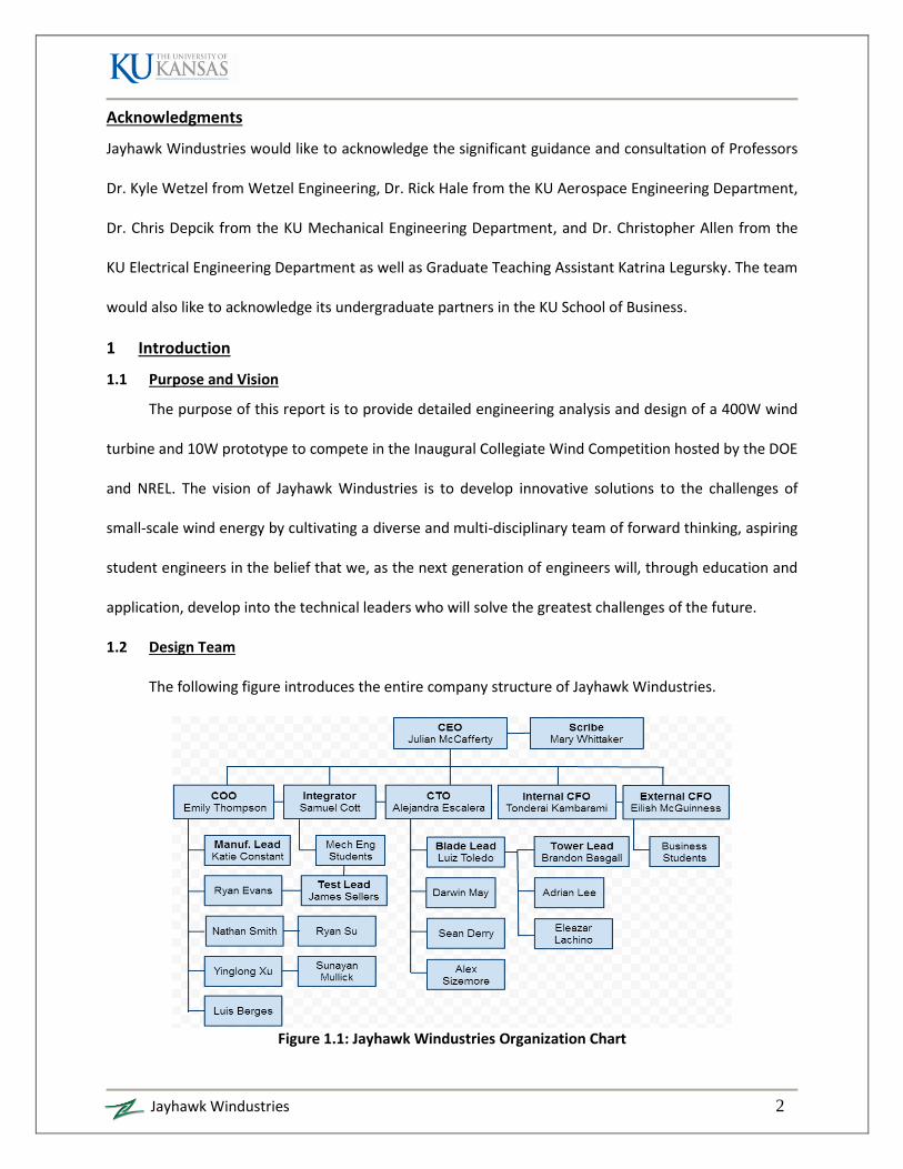
The following figure introduces the entire company structure of Jayhawk Windustries.
Figure 1.1: Jayhawk Windustries Organization Chart

Jayhawk Windustries 3
Table 1.1: Jayhawk Windustries Spring Team
Team Member Background Responsibilities
Katie Constant, AE, Market Research Lead
Coursework in Wind Turbine Design
Extensive research capabilities
Research and application of turbine in specific markets
Market issues research and presentation
Alejandra Escalera, AE, Chief Technical Officer
International student from Bolivia
Coursework in business concepts
Review of all designed components
Communication facilitation with manufacturing team
Technical advisor for design team
Andrew Lichter, ME, Designer
Internship with Flint Hills Resources
Extensive coursework in mechanical design
Emergency shutdown system
Incorporation of disc crake into gearbox
Designed brake actuation components and layout
Julian McCafferty, AE, Chief Executive Officer
Air Force Cadet Leadership Experience
Leadership Studies
Coursework in Wind Turbine Design
Composites and Manufacturing Experience
Direction and vision of the company
Employee welfare and team moral
Meeting company objectives and deadlines
Final Design reviews and decision making
Evan Reznicek, ME, Mechanical Team Lead
Extensive coursework in mechanical design & alternative energy
Research experience in small wind energy technology
Lead team in designing power train
Designed gear drive and power electronics
James Sellers, AE, Testing Team Lead
Air Force Cadet Leadership Experience
Extensive experience in CAD and graphic illustration
Coursework in Wind Turbine Design
Interest in test and evaluation
Concept design using CAD
Prototype development
Product test and evaluation
Company graphics development
Alex Sizemore, AE, Designer
Coursework in structural analysis and FEA Business plan development
Blade Structure and Design
Emily Thompson, AE, Chief Operating Officer
Air Force Cadet Leadership Experience
Coursework in Wind Turbine Design
Prototype manufacturing
Quality control and safety
Mary Pat Whittaker, AE, Executive Assistant
Multiple years experience in assistant positions
Lab technician for AE department, specifically running
wind tunnels
Travel arrangements
Competition submission materials
Communication facilitation
Aid to all departments in reaching overall goal
Preliminary wind tunnel testing

Jayhawk Windustries 4
1.3 Design Objective
This report details the design of the prototype wind turbine to be tested in the wind tunnel at the
competition, and the market turbine in accordance with the Jayhawk Windustries Business Plan. The
design objective of the prototype wind turbine is to provide maximum commonality with the market
turbine, while meeting all performance requirements outlined in the 2014 Collegiate Wind Competition
Rules1. The objective of the market design is to provide a safe, high performance, durable, affordable,
and portable turbine to power provisional project sites and electronic equipment of global Non-
Governmental Organizations (NGOs) with the potential to expand to additional markets.
The following merit criteria were developed to determine the design approach, materials, and
processes for the wind turbine with a respective weighting for its influence on the design.
Table 1.2: Market Merit Criteria
Weighting System Percentage
Safety 25%
Performance 20%
Maintainability 20%
Procurement Cost 15%
Life Cycle Cost 10%
Portability 10%
TOTAL 100%
Safety considerations include labor safety, structural margins, and most importantly risk
reduction of injury to the customer. Performance includes providing a competitive $/Watt to the
competition and power generation to meet the needs of the customer. Maintainability is defined as the
turbine’s repairability, ease of access, and simplicity of the design. Minimizing the procurement cost
requires appropriate and efficient manufacturing, processing, and facilities. Minimizing life cycle cost
entails providing durable and lasting components with simple and low cost parts replacement. Finally,
portability affects parts count, weight, size, breakdown and assembly, and is considered as a necessary
feature for NGOs and other customers with operating sites that move at least once per year.

Jayhawk Windustries 5
This wind turbine is differentiated from the market by featuring a shrouded rotor for safety and
added performance, a hub-less rotor for low parts count, and a collapsible design to maximize
portability. This assemblage of characteristics is currently unavailable on the market.
2 Market Wind Turbine
Table 2.1: Market Turbine Design Specifications
Rated Power Configuration Rated Speed Rotor Diameter Speed Configuration
400 W Horizontal Axis 12 m/s 1 meter Variable Speed
The Market Turbine is a power regulated, geared, variable speed, 3-bladed horizontal axis upwind
turbine (HAWT). Since this is a small turbine, a pitch regulation system would be too costly and complex,
but a variable speed rotor is necessary to track optimal TSR for maximum energy capture of IEC Class III
wind speeds. A 3-bladed rotor was chosen to minimize tower top oscillation and blade length for
portability. An upwind HAWT configuration was chosen to provide the blades clean air and because it
generally has greater efficiency over Vertical Axis Turbines which is critical for low wind speeds. The only
disadvantage is the necessity to account for blade strike. The scale of the market turbine is constrained
to maintain portability while providing adequate power to the customer.
2.1 Airfoil Selection
The market turbine airfoil is the SG6040 selected from the UIUC Airfoil Database2. The SG6040
Airfoil has been wind tunnel tested and is selected because it does not exhibit laminar separation for
lower Reynolds numbers of small wind turbines, and because it provides a larger thickness to chord ratio
for improved structural margins.
Figure 2.2: SG6040 Airfoil
-1
-0.5
0
0.5
1
1.5
-40 -20 0 20 40
Angle of Attack, α (deg)
Lift Coefficient, Cl
Figure 2.1: SG6040 Lift Coefficient Data2

Jayhawk Windustries 6
2.2 Blade Design
The market turbine was designed using a programmable excel spreadsheet provided in Dr.
Wetzel’s design course in which chord and twist is iterated to maximize power output using designed
and assumed parameters such as TSR, rotor diameter, and efficiencies. The geometry and stall regulated
idealized power curve are given below assuming an electromechanical efficiency of 0.9. The blade
design evolution is adopted from the prototype blades detailed in the prototype design section.
Table 2.2: Market Turbine Blade Geometry
Z node (m) Chord (m) Twist (deg)
0.075 0.070 11.00
0.125 0.050 10.00
0.175 0.040 8.00
0.225 0.030 5.00
0.275 0.025 3.00
0.325 0.021 1.00
0.375 0.020 0.00
0.425 0.016 -1.00
0.475 0.010 -2.00
0.500 0.010 -3.00
2.3 Materials
In order to determine the optimal materials and processes for the manufacturing of the market
turbine, Jayhawk Windustries contracted a series of undergraduate consultant tiger teams representing
distinct companies but comprising of students from the main team to provide cost benefit analyses and
structural engineering work for 300, 3,000, and 30,000 turbines per year production rates. Jayhawk
Windustries provided the merit criteria from Table 1.2, reviewed each report and presentation, and
selected the following recommendations from Sirius Consulting. The estimated cost per blade includes
materials, tooling, labor, overhead, machine procurement, and operational costs.
Table 2.3: Sirius Consulting Recommendation to Jayhawk Windustries4
Blade (3 per Turbine)
Manufacturing Process Injection Molding, In-house
Material RTP 2289 HM Plastic (50% Carbon Fiber)
Estimated Cost/Part $13.77 (900/year), $10.43 (9,000/year), $10.30 (90,000/year)
Figure 2.3: Market Turbine Power Output, Regulated at 400 W

Jayhawk Windustries 7
2.4 Loads
The following loading simulations of IEC 61400-1 DLCs were performed using FAST v7.02 and
AeroDyn v13.00 and TurbSim analysis software. This simulation software is publically available on the
NREL website. The TurbSim software creates a stochastic, full-field, turbulent-wind model using a
statistical model and three-component wind speed vectors5.
DLC 1.1 (NTM) for
DLC 1.1 (NTM) for
The FAST/AeroDyn software models the dynamic response of
conventional horizontal-axis wind turbines6. This software was used to
generate blade loads and analyze the turbine’s dynamic response to
different wind case scenarios. Table 2.4 summarizes the simulated
results and analyzed structural margins of safety. A DLC 6.1 of extreme winds at 37.5 m/s is not analyzed
because the turbine is not designed to withstand those loads. The user will be instructed to disassemble
the turbine before subjecting it to extreme winds above 20 m/s until further maximum loads testing is
completed. RTP 2289 HM Plastic Material Properties are found in Reference 7.
Table 2.4: Loading Simulation Results and Analysis
Trial
Blade Root Flapwise Bending
Moment (N-m)
Tower-Top Thrust (N)
Tower-Top
Bending Moment
(N-m)
Design Load, M-y/I (Pa)
Failure Load (Pa) Margin of Safety
Edgewise Flapwise Edgewise Flapwise Edgewise Flapwise
DLC 1.1 Vavg = Vout
Max 18.9 95.04 9.82
9.92E+05 2.72E+06 4.60E+06 1.01E+07 3.64 2.8 Min 8.00 43.9 3.41
DLC 1.1 Vavg = Vrated
Max 20.0 101.0 10.5
1.06E+06 2.87E+07 4.60E+06 1.04E+07 3.36 2.5 Min 13.2 72.2 7.51
Table 2.4 only includes the bending moments seen at the root of the blade because they are
known to be the critical load. The flapwise and edgewise results were used to calculate the margin of
safety for each condition based upon the geometry and material properties for the market turbine; each
blade is predicted to safely meet material design allowables as seen by the positive margins of safety.
Figure 2.4: TurbSim Flow-Field Model Example5

Jayhawk Windustries 8
2.5 Drivetrain Components
The gear drive is necessary to increase generator shaft speed in order to increase generator
voltage output. To produce 400 W, the generator must produce at least 17 V RMS, meaning it must spin
at approximately 34000 rpm. With a rotor speed
of 1770 rpm, this requires at least a 19.2:1 gear
ratio. To achieve this, the 24-28 mm Ammo
Motor Great Planes Planetary Gear Drive was
combined with a custom designed parallel shaft
gear drive. The planetary gear drive has a gear
ratio of 4.3:1 and the parallel shaft gear drive has a
gear ratio of 4.5:1. Thus, their combined gear ratio (generator speed/rotor speed) is 19.35:1. A 0.375
inch rotor shaft was selected, along with two flange mounted bearings. The rear bearing is a radial ball
bearing that has an extended collar to allow axial constraint of the shaft and take axial thrust load. The
spur gear is constrained to the rotor shaft with a locking set screw, and the parallel shaft gear drive
pinion is constrained to the planetary gear drive shaft with a second locking set screw. Two 6061
aluminum plates spaced by 0.75 inch standoffs house the parallel shaft gear drive. Drivetrain
components and layout are shown in Figure 2.5.
Calculations were performed to ensure that the shaft and bearings would be sufficient to handle
loads created by the rotor. Shaft calculations using the Modified Goodman Equation yielded a factor of
safety of approximately 18.7, indicating that even at rated power and speed, the shaft will experience
infinite life. The bearings have a dynamic load rating of 580 lbs or 2580 N, and a calculated maximum
reaction force on the rear bearing of 380 N. This results in bearing life of 3.205 x 10⁸ cycles, and
approximately 5550 operating hours using a Rayleigh Distribution of IEC Class III Winds. These
calculations show that the shaft and bearings selected are sufficient to handle rotor loading; however,
Figure 2.5: Turbine Drivetrain; layout minimizes cross-sectional area

Jayhawk Windustries 9
designed lifespan should be increased by improving bearing quality and relieving loading to achieve a
product lifespan of 10 years assuming continuous annual operation.
The purpose of the mechanical emergency brake is to ensure that the turbine has a fail-safe
method of braking. This brake allows a user to physically lock the rotor from turning. A hydraulic disc
brake system was designed using parts from a GTB hydraulic system disc brake kit. Brackets were
fashioned to allow the brake caliper to mount in front of the gear drive. A 2.5 inch 316 stainless steel
washer was adapted to serve as the brake disc, as the brake kit discs were too large. The brake kit
master cylinder is mounted behind the gear drive, next to the generator. Dot3 brake fluid is pumped
from the master cylinder, through a brake line that runs through the gear drive, into the caliper to clamp
the brake pads and slow the rotor. This brake is actuated via a lever and bicycle brake cable mounted at
the back of the turbine. A user clamps down on a bicycle brake lever, which pulls on the brake cable,
pulling one side of the lever back, and pushing the other side of the lever forward, compressing the
piston inside of the master cylinder and pumping fluid to the caliper. Reference the supplemental
computer drawings document for the turbine drivetrain.
Figure 2.6 shows a schematic diagram of the power electronics system. Though the designed
gear-drive optimizes generator speed for
rated power output, it is not sufficient to
step up the generator voltage to overcome
the potential of a 12 V DC battery for wind
speeds lower than 10 m/s. To further step up the voltage at a lower cost, a power transformer is placed
in parallel with the gearbox. This transformer operates as long as the voltage produced by the generator
is below 14 V RMS. Once the generator voltage exceeds 14 V RMS, a micro-processor will switch a relay
such that the transformer is bypassed. This approach is used because at voltages above 14 V RMS the
transformer is not necessary. In addition, if the transformer is selected such that it can also handle the
Figure 2.6: Power Electronics Schematic Diagram

Jayhawk Windustries 10
high currents seen at voltages about 14 V RMS, transformer cost may become prohibitive. By using a
micro-processor and relay to selectively employ the transformer, utility and cost are enhanced.
Because the generator produces alternating current, it is necessary to employ a rectifier to
produce a clean DC signal, so the power produced by the generator can be used to charge a 12 V DC
battery or power a 12 V DC load. A bridge diode rectifier was selected for its simplicity and low cost.
Shaft speed is controlled by controlling the duty cycle of an
insulated gate bipolar transistor (IGBT) placed between the rectifier
and the power sink. A propeller microprocessor is used to control
this duty cycle. The microprocessor is programmed to adjust duty
cycle in order to maximize power produced, until the turbine
reaches its rated power. Figure 2.7 shows a logic diagram of the
shaft speed control algorithm.
The controller can also be used to slow the turbine when the
load is disconnected. A relay is placed in parallel between the
generator and the transformer, but in series with a dump load.
During normal operation the relay remains open all the time. When
the load is disconnected, the controller will sense this by measuring a current of zero at the point of
common coupling. It will then command the relay to close, short-circuiting the generator. The current
seen by the generator will be large enough to slow the rotor to a safe speed.
2.6 Nacelle, Tower, and Furling
The nacelle and tail is injection molded from the same RTP 2289 HM Plastic as the rotor to
maintain high production runs and drivetrain protection. The market turbine will incorporate a variable
height tower by using commercial 3 ft long, 3 inch diameter, partially threaded 316 stainless steel rods
and tie downs. The customer can achieve the desired hub height by assembling up to 5 rods, or 15 ft
Figure 2.7: Power Control Algorithm; Controller actively measures power and adjusts duty cycle to track maximum
power point

Jayhawk Windustries 11
additional height to operational elevation. Preliminary
vibrations analysis of the blade passage through the tower,
not shown here, sized the tower diameter to 3 inches.
The market turbine will include a passive tail vane
for tower top yawing to track the wind. This is often the
most effective yawing mechanism for small wind turbines
due to the low torque required. Final tower top weight is
not yet determined, so the tail preliminary size is 1 sq ft surface area with a center of pressure 1.5 feet
from the rotation point. The turbine tail is also an opportunity to implement a profile evocative of the
Jayhawk Windustries logo in order to build company recognition.
2.7 Shroud
The market turbine will have a shrouded rotor to address the safety and performance of the
turbine for a marginal increase in cost. Diffuser Augmented Wind Turbines (DAWTs) have been tested
and implemented on small commercial wind turbines very
similar to this 1 meter diameter design. This is accomplished
by capturing and accelerating the air through the rotor as
seen in Figure 2.10. Debate exists over actual augmentation
achieved outside of controlled testing, but a thesis paper
from the University of Auckland claims to have addressed these concerns and still achieved a 2.02
augmentation8. As this is a preliminary design report, the engineering of the shroud is not complete and
will require further testing, analysis, and potential redesign of the blades. The turbine design will not
claim power augmentation until this detailed work is accomplished.
Figure 2.10: DAWT Flow Field9
Figure 2.9: Nacelle and Tail Vane
Figure 2.8: Market Turbine Tower sized by vibration analysis

Jayhawk Windustries 12
3 Prototype Wind Turbine
Table 3.1: Prototype Turbine Design Specifications
Rated Power Configuration Rated Speed Rotor Diameter Speed Configuration
18 W Horizontal Axis 10 m/s 17 in Variable Speed
The electromechanical and turbine configuration remains consistent between the prototype and
market turbine to maintain maximal commonality with size and features. The prototype turbine includes
a custom built Gearbox with a gear ratio of 4.55: 1.
3.1 Airfoil Selection
The prototype turbine airfoil is the
NeoEnergy NE203, a custom designed airfoil for
10 – 200k Reynold’s numbers. Data for this airfoil
was provided by Dr. Wetzel from wind tunnel
testing for a 100W turbine. The prototype turbine
will operate well under Re = 100k, so this airfoil is
much more appropriate for the small scale
turbine than the SG6040 airfoil.
3.2 Blade Design
A blade optimization tool was used for the
prototype that produces over 80,000 different combinations of chord and twist based on a desired TSR,
rotor/hub diameter, max chord, etc. The blade geometry with the highest performance was selected;
however, this design did not account for manufacturability or structural design. The first iteration design
below was prototyped using selective laser sintering and tested for aerodynamic and structural
performance.
Figure 2.3: First Iteration Blade Design from Optimization Tool
-1
-0.5
0
0.5
1
1.5
2
-100 -50 0 50 100
Angle of Attack, α (deg)
Lift Coefficient, Cl
Figure 3.1: NE203 Wind Tunnel Data
Figure 3.2: NeoEnergy NE203 Airfoil

Jayhawk Windustries 13
In order to improve the structural quality and
tip deflections, the chord lengths were increased along
the span and root for increased structural margins and
the trailing edge wall thickness was increased for
improved layering in 3-D printing. These modifications
affect ideal theoretical aerodynamic performance, but
are exchanged for safety, manufacturability, durability,
and life cycle cost. The first iteration design required
nine 2mm M2 screws, M2 washers, hex nuts, and significant patience for assembly. This did not comply
with the concept of portability and ease of operation, so the design team minimized parts count and
assembly time by implementing a hub-less design with just 3 larger socket cap screws shown below.
Figure 3.4: Second Iteration Blade Design; Chords and thickness adjusted to increase stiffness
Figure 3.5: Integrated hub and blade design to reduce parts count and assembly time for portability
The optimized geometry for the prototype turbine was used to predict the rotor performance.
Figure 3.3: First iteration design in small wind Tunnel Testing provided preliminary aerodynamic results

Aerospace Engineering Department 14
Figure 3.6: Aerod Power Coefficient vs. TSR Figure 3.7: Aerodynamic Power vs. Wind Speed
The designed turbine cut-in speed is 2 m/s and is optimized for 16-18 W at 9-17 m/s as shown below.
Table 3.2: Prototype Blade Geometry
Z node (in) Chord (in) Twist (deg)
0.043 0.021 13.75
0.064 0.021 13.75
0.086 0.020 13.75
0.108 0.017 13.75
0.129 0.015 11.625
0.151 0.014 9.75
0.173 0.013 9.125
0.194 0.013 8.25
0.216 0.010 0.18
3.3 Loads
The prototype blades are selective laser sintered from Nylon 12 Glass Fiber purchased from
Solid Concepts. This was chosen for its relatively high Young’s modulus and aerodynamic finish. The
manufacturer reported material properties are found in Reference 3. The edgewise and flapwise
forces and moments are the critical loads acting on the blade as determined by the blade optimization
code. A 1.42N, or 0.319 lbf, flapwise force is calculated using a 2-dimensional flat plate in 17 m/s wind
and a 2.0 drag coefficient. Both hand calculations and an FEM model using PATRAN 2012.2 were used
to verify blade deflections.
0.00
0.05
0.10
0.15
0.20
0.25
0.30
0.35
2.00 4.00 6.00 8.00
Aer
o P
ow
er C
oef
fici
ent
Tip Speed Ratio
0.00
0.05
0.10
0.15
0.20
0.25
0.30
0.35
0.00 5.00 10.00 15.00 20.00
Aer
o P
ow
er C
oef
fcie
nt
Wind Speed, m/s
0
5
10
15
20
0 2 4 6 8 10 12 14 16 18
Po
we
r (W
)
Wind Speed (m/s)
Figure 3.8: Power vs. Wind Speed

Aerospace Engineering Department 15
For a distributed load over a cantilevered beam:
Average blade dimensions listed below were used to calculate deflection assuming a flat beam.
Average thickness = 0.0025 m, 0.0082 ft
Average chord = 0.02 m, 0.066 ft
Nylon 12 GF Flexural Modulus = 2.24 GPa, 324.88 ksi
The design team assumed that the distributed load acts directly on the face of the blade.
( )( )
( )( )
( )( )
A PATRAN model was developed to measure the static and dynamic blade deflections. The blade was
approximated as seven flat plates with the following dimensions.
Table 3.3: FEM Blade Geometric Specifications
Section Thickness (in) Avg Chord (in)
1 0.275 1.325
2 0.125 0.958
3 0.090 0.808
4 0.080 0.712
5 0.073 0.565
6 0.068 0.511
7 0.050 0.429
Figure 3.9: FEM Blade Sections
The geometry was then meshed into 136 rectangular elements and a pressure load of 0.0513
psi at 17 m/s wind speed was applied along the entire span with the root fixed at the location of the
bolts. Next, an inertial load at 2000 rpm was added to the model at the axis of rotation.

Aerospace Engineering Department 16
Figure 3.10: FEM Pressure Load Blade Deflection
Figure 3.11: FEM Pressure and Inertial Load Blade Deflection
Table 3.4: Pressure and Inertial Load Deflections
The pressure load model resulted in a flapwise displacement of 0.528 inches, or 1.34 cm. The
rotor to tower distance is 6.03 inches, leaving a 5.50 inch clearance at 17 m/s. This result is lower than
calculations, further validating adequate blade deflections. The second model includes the inertial load
Tip Deflections (in)
X 0.320
Y 0.666
Z 0.528
Magnitude 0.909

Aerospace Engineering Department 17
at the maximum 2,000 rpm with moderate deflections shown in Table 3.4. These deflections appear
large but are still within margins. Furthermore, the rotor has been tested as high as 4,000 rpm and
have not exhibited failure or flapwise and edgewise deflections greater than 0.5 inches by inspection.
Using the previously derived 1.42 N, or 0.319 lbf, pressure load, the flapwise bending moment is
0.16 N-m, or 0.12 ft-lbf. This results in a bending stress of 7.48 MPa, or 1.085 ksi, with a material
flexural strength of 61 MPa, or 8.85 ksi, and Margin of Safety of 7.16. The edgewise bending moment is
calculated to be 0.44 N-m, or 0.32 ft-lbf, for the 18 gram blade spinning at 2000 rpm to a complete
stop in half of a second. The loaded stress is 0.249 MPa, or 0.036 ksi, and the calculated Margin of
Safety is 23.52. These calculations assume a simple constant area cantilever beam and will be validated
with testing.
3.4 Drivetrain Components
The drivetrain components of the prototype turbine were designed based off those of the
market turbine. Because the power required for the prototype turbine is significantly lower, only a
single step parallel shaft gear drive was employed. This gear drive employs an 11 tooth pinion and a 50
tooth spur gear equipped with a 5 mm bore hub and locking set screw. These gears are again housed
by two 6061 aluminum plates spaced by 0.75 inch standoffs. 5 mm flanged roller ball bearings are
mounted in these plates to support a 5 mm rotor shaft. These bearings support radial and axial thrust
load. The shaft is constrained axially by the placement of Belleville disc washers in between the spur
gear and the bearings. The washers essentially constrain the spur gear between the bearings, and
because the spur gear is constrained to the shaft via a locking set screw, this also constrains the shaft
axially. Results of employing the Modified Goodman Equation indicate a factor of safety of
approximately 30. The bearings have a dynamic load rating of 97 lbs or 431 N, and a calculated
maximum reaction force on the rear bearing of 23.4 N. This results in bearing life of 6.25 x 10⁹ cycles,
or roughly 52,000 hours (slightly less than six years) operating at a constant 2000 revolutions per

Aerospace Engineering Department 18
minute. These calculations show that the shaft and bearings selected are sufficient to handle rotor
loading. The mechanical brake system for the competition turbine is identical to that of the market
turbine, except for minor adjustments in placement of components, and use of a 2 inch diameter
washer to reduce nacelle dimensions. Computer aided drawings of the drivetrain are provided in the
supplemental document and shown in Figure 2.5.
The power electronics of the prototype turbine are also very similar to those of the market
turbine; the primary differences are of size and capacity. Because the prototype turbine will not
produce as much current, even at high power outputs, the transformer is allowed to remain in use
throughout the entirety of the turbine’s power regime. In addition, the voltage of the DC Power Sink is
5 VDC, rather than 12 VDC. This difference necessitates different sized resistors, transistors, and
transformer. The controller performs the same functions as those of the market turbine. Figure 2.6
shows a schematic diagram of the competition turbine electronics.
4 Power Electronics and Drivetrain Testing
4.1 Generator Testing
Testing was performed frequently to identify design characteristics and parameters. The zero
load voltage-shaft speed relationship of the generator was determined by spinning the generator with
a cordless drill, and measuring voltage output with a digital multimeter. This relationship was used to
determine the gear drive gear ratio and transformer ratio necessary to increase the voltage to a value
high enough to allow the turbine to inject current out of the rectifier and into the load.
4.2 Wind Tunnel/Power Electronics Testing
Early wind tunnel testing focused on identifying the performance characteristics of the rotor by
varying the load resistance at each wind speed with a rheostat. Preliminary tests were performed in a
small wind tunnel, but this presented problems, as tunnel wall boundary effects prevented accurate
measurement of wind speed in the rotor plane. Subsequent tests in a larger wind tunnel were more
useful. A 5 V DC Dell computer power supply capable of sourcing 35 amps was employed with two 0.1

Aerospace Engineering Department 19
ohm 100 W resistors to replicate the competition power
sink. At first the team tested the turbine without any
control, to determine if an uncontrolled turbine would meet
any of the competition requirements. Because the low
resistance of the load restricted shaft speed (and thus
power) at all wind speeds, a rheostat was placed in series
with the rectifier and load, in order to vary load resistance
and imitate the effect of a controlled DC buck converter. Results indicated that varying the load
resistance as seen by the generator could allow for power optimization. To minimize resistive loss, an
insulated gate bipolar transistor was selected as the switching element for the buck converter. To
date, the prototype rotor and drivetrain has been wind tunnel tested for a total of 1.5 hours at an
average speed of 1200 rpm. No structural degradation or hysteresis has been recorded in the
performance data.
5 Conclusions
This report details the process by which a 1 meter diameter 400W HAWT was designed by
Jayhawk Windustries. The 400W turbine is sized to address the market needs described in the Jayhawk
Windustries Business Plan. A small scale prototype is fabricated for design validation and testing.
Multiple iterations of blade and gearbox design are accomplished and the design is supported by
structural analysis and wind tunnel testing data. A power control system is designed and determined
to be necessary for optimal tracking of TSR and performance. The preliminary design addressed in this
research is safe for testing, and demonstrates the market potential for the larger market turbine,
though the latter requires further testing and iterations to address safety, portability, and shroud
performance augmentation before a final product is brought to the market.
Figure 4.1: Large Wind Tunnel Testing; Used to test power electronics and
performance

Aerospace Engineering Department 20
6 References
[1] DOE/NREL, “2014 U.S. Department of Energy Collegiate Wind Competition RULES AND
REQUIREMENTS Version 1.1”, Updated Nov 15, 2013.
[2] UIUC Applied Aerodynamics Group, “UIUC Airfoil Coordinates Database”, Ver 2.0 2014.
[http://aerospace.illinois.edu/m-selig/ads/coord_database.html]
[3] L. Berges, E. Thompson, L. Toledo, “Sirius Consultation Manufacturing Proposal”. Nov 2013.
[4] Solid Concepts, “Prototype SLS Material Specifications”, Nylon 12 GF. 2013.
[https://www.solidconcepts.com/content/pdfs/material-specifications/sls-nylon-12-gf.pdf]
[5] B.J. Jonkman, “TurbSim User’s Guide: Version 1.50”, National Renewable Energy Laboratory.
Sep 2009. [http://www.nrel.gov/docs/fy09osti/46198.pdf]
[6] Jason M. Jonkman, Marshall L. Buhl Jr. “FAST User’s Guide”, NREL. Aug 2005.
[http://wind.nrel.gov/designcodes/simulators/fast/fast.pdf]
[7] RTP Company, “RTP 2289 HM Data Sheet”, Polyetheretherketone 50% Carbon Fiber.
[http://plastics.ides.com/datasheet/e29833/rtp-2289-hm]
[8] Phillips, Derek Grant, “An Investigation on Diffuser Augmented Wind Turbine Design”, PhD
Thessis, Department of Mechanical Engineering, University of Auckland. 2003
[9] K. M. Foreman, “Preliminary Design and Economic Investigations of Diffuser Augmented Wind
Turbines (DAWT)” Final Report, Grumman Aerospace Corporation Research Department. 1981.