Final Design Report Design of Secondary Heat Exchanger...
113
Final Design Report Design of Secondary Heat Exchanger for the HT 3 R Submitted to: Steven Biegalski, Ph.D., P.E., Assistant Professor Nuclear Engineering Teaching Laboratory Austin, Texas Prepared by: Kevin Thuot Scott Waters, Team Leader David Wogan Mechanical Engineering Design Projects Program The University of Texas at Austin Austin, Texas August 8, 2006
Transcript of Final Design Report Design of Secondary Heat Exchanger...

Final Design Report
Design of Secondary Heat Exchanger for the HT3R
Submitted to:
Steven Biegalski, Ph.D., P.E., Assistant Professor Nuclear Engineering Teaching Laboratory
Austin, Texas
Prepared by:
Kevin Thuot Scott Waters, Team Leader
David Wogan
Mechanical Engineering Design Projects Program The University of Texas at Austin
Austin, Texas
August 8, 2006


High Temperature Teaching and Test Reactor Pre-Conceptual
Design
Secondary Heat Exchanger Design Report
Prepared by Kevin Thuot, Scott Waters, and David Wogan
For the University of Texas of the Permian Basin
GA CONFIDENTIAL AND PROPRIETARY INFORMATION: THIS DOCUMENT WITH ANY ATTACHMENTS CONTAINS GENERAL ATOMICS (GA) CONFIDENTIAL AND PROPRIETARY INFORMATION. ANY TRANSMITTAL OF THIS DOCUMENT OUTSIDE GA WILL BE IN CONFIDENCE AND SUBJECT TO THE NON-DISCLOSURE PROVISIONS OF THE APPLICABLE AGREEMENT OR AGREEMENTS. THE INFORMATION CONTAINED IN THIS DOCUMENT MAY BE USED BY THE RECIPIENT ONLY FOR THE PURPOSE FOR WHICH IT WAS TRANSMITTED AND MAY NOT BE COMMUNICATED TO OTHERS EXCEPT WITH THE WRITTEN CONSENT OF GA.
August 8, 2006

GA 2175 (1199E) PROJECT CONTROL ISSUE SUMMARY
DOC. CODE PROJECT DOCUMENT NO. REV. 0
TITLE: High Temperature Teaching and Test Reactor Pre-Conceptual Design Secondary Heat Exchanger Design Report
APPROVALS CM APPROVAL
/ DATE REV. PREPARED BY RESOURCE/
SUPPORT PROJECT
REVISION DESCRIPTION/ W.O.
NO.
K. Thuot W.S. Waters D. Wogan
X GA PROPRIETARY INFORMATION THIS DOCUMENT IS THE PROPERTY OF GENERAL ATOMICS. ANY TRANSMITTAL OF THIS DOCUMENT
OUTSIDE GA WILL BE IN CONFIDENCE. EXCEPT WITH THE WRITTEN CONSENT OF GA, (1) THIS DOCUMENT MAY NOT BE COPIED IN WHOLE OR IN PART AND WILL BE RETURNED UPON RQUEST OR WHEN NO LONGER NEEDED BY RECIPIENT AND (2) INFORMATION CONTAINED HEREIN MAY NOT BE COMMUNICATED TO OTHERS AND MAY BE USED BY RECIPIENT ONLY FOR THE PURPOSE FOR WHICH IT WAS TRANSMITTED.
NO GA PROPRIETARY INFORMATION PAGE ii OF 59


Acknowledgments
The Secondary Heat Exchanger Team would like to thank our sponsor, The
Nuclear Engineering Teaching Laboratory, for the opportunity to work on this project.
The ability to be involved with such an important project from the beginning phase has
been very rewarding. We would also like to thank our faculty advisor Dr. David Bogard
for his continued guidance and exceptional insight into the details of our project. Thanks
must also be given to Dr. Richard Crawford and our teaching assistant, Lalit Karlapalem,
for their assistance with the written reports and presentations.


TABLE OF CONTENTS
Title Page
Issue/Approval Summary
Acknowledgments.................................................................................................................. i
Table of Contents................................................................................................................... iii
List of Figures........................................................................................................................ vii
List of Tables......................................................................................................................... ix
List of Acronyms................................................................................................................... xi
Variable Nomenclature.......................................................................................................... xiii
Executive Summary............................................................................................................... xvii
1. Introduction................................................................................................................ 1
1.1 Sponsor Background...................................................................................... 1
1.2 Project Background........................................................................................ 2
1.3 Problem Statement......................................................................................... 5
1.4 Requirements................................................................................................. 5
1.5 Constraints..................................................................................................... 5
1.6 Deliverables................................................................................................... 6
1.7 Specification Sheet......................................................................................... 6
2. Patent Search.............................................................................................................. 9
2.1 U.S. Patent #6,888.,910: Methods and Apparatuses
for Removing Thermal Energy from a Nuclear Reactor............................... 9
2.2 U.S. Patent #4,699,211: Segmental Baffle High Performance
Shell and Tube Heat Exchanger..................................................................... 10

iv
2.3 U.S. Patent #4,483,392: Air to Air Heat Exchanger...................................... 10
3. Alternative Designs.................................................................................................... 12
3.1 Traditional Cooling Tower............................................................................ 14
3.2 Heat Pipes...................................................................................................... 16
3.3 Radiative Heat Transfer................................................................................. 18
3.4 Flat Plate Heat Exchanger.............................................................................. 20
3.5 Printed Circuit Heat Exchanger .................................................................... 22
3.6 Shell and Tube Heat Exchanger..................................................................... 23
3.6.1 Shell and Tube Configurations.......................................................... 23
3.6.2 Shell and Tube Vendor Information.................................................. 25
3.7 Air Cooled Heat Exchanger........................................................................... 27
3.7.1 ACHE Design and Operation............................................................. 27
3.7.2 ACHE Vendor Information................................................................ 30
3.8 Recuperator.................................................................................................... 30
4. Project Solution.......................................................................................................... 33
4.1 Shell and Tube Design................................................................................... 33
4.2 ACHE Design................................................................................................ 39
4.3 Design Comparison........................................................................................ 42
4.4 Economic Analysis........................................................................................ 43
5. Computer Models....................................................................................................... 45
5.1 Heat Exchanger Simulation........................................................................... 45
5.2 Matlab Codes................................................................................................. 47
5.2.1 Mass Flow Analysis........................................................................... 47

v
5.2.2 Gas Calculator.................................................................................... 48
5.3 Solid Modeling.............................................................................................. 49
6. Recommendations and Conclusions.......................................................................... 52
6.1 Future Design Recommendations.................................................................. 52
6.1.1 Gas Exit Temperature Control System.............................................. 53
6.1.2 Dual Material ACHE......................................................................... 54
6.1.3 Air Exhaust Temperature................................................................... 55
6.1.4 Air Filtration...................................................................................... 56
6.2 Conclusions.................................................................................................... 57
7. References.................................................................................................................. 59
Appendix A: Gantt Chart......................................................................................... ........... A-1
Appendix B: Radiative Heat Transfer Analysis.................................................................. B-1
Appendix C: Vendor Information....................................................................................... C-1
Appendix D: Simulink Model............................................................................................. D-1
D.1 Simulink Model Validation............................................................................ D-2
D.2 Simulink Code............................................................................................... D-5
Appendix E: Matlab Code/Analysis.................................................................................... E-1
E.1 Mass Flow Analysis....................................................................................... E-2
E.2 Air Cooled Heat Exchanger Design............................................................... E-4
E.3 Shell and Tube Heat Exchanger Design........................................................ E-8

vi

vii
LIST OF FIGURES
Figure 1. Engineering and Construction Schedule Through 2012................................ 2
Figure 2. Reactor Schematic......................................................................................... 4
Figure 3. Hyperbolic Cooling Tower............................................................................ 14
Figure 4. Fill Media....................................................................................................... 15
Figure 5. Heat Pipe Diagram......................................................................................... 17
Figure 6. Variation of Fluid Temperature as a Function of Pipe Length...................... 19
Figure 7. Corrugated Plates........................................................................................... 21
Figure 8. Heatric PCHE................................................................................................. 22
Figure 9. Fixed Tube-Sheet........................................................................................... 23
Figure 10. U-tube............................................................................................................ 24
Figure 11. Floating Head................................................................................................. 24
Figure 12. Des Champs Thermo-T Shell and Tube Heat Exchanger.............................. 26
Figure 13. ACHE Operation............................................................................................ 28
Figure 14. Forced Draft ACHE....................................................................................... 29
Figure 15. Induced Draft ACHE..................................................................................... 29
Figure 16. Schematic with Recuperator.......................................................................... 31
Figure 17. Nitrogen Gas Path Through Shell and Tube HX........................................... 36
Figure 18. Air Path Through Shell and Tube.................................................................. 36
Figure 19. Baffle Window Effect on Overall Heat Transfer Coefficient........................ 37
Figure 20. Secondary Heat Exchanger Simulink Model................................................. 46
Figure 21. Dependence of Outlet Temperature on Mass Flow Rate............................... 48
Figure 22. Ecodyne Air Cooled Heat Exchanger............................................................ 49

viii
Figure 23. Solidworks Model of Ecodyne Design.......................................................... 50
Figure 24. Shell and Tube Solidworks Model................................................................. 51
Figure B.1 Heat Transferred Versus Pipe Length............................................................ B-3
Figure B.2 Fluid Temperature Versus Pipe Length......................................................... B-3
Figure D.1. Exit Temperature Dependence on Gas Flow Rate......................................... D-3
Figure D.2. Pressure Drop Dependence on Gas Flow Rate.............................................. D-4

ix
LIST OF TABLES
Table 1. Requirements................................................................................................. 5
Table 2. Constraints..................................................................................................... 6
Table 3. Specification Sheet......................................................................................... 8
Table 4. Proposed Solutions........................................................................................ 13
Table 5. Shell and Tube Properties.............................................................................. 35
Table 6. ACHE Properties........................................................................................... 41
Table 7. Heat Exchanger Model Comparison.............................................................. 42
Table C.1. Vendor List.................................................................................................... C-2

x

xi
ACRONYMS ACHE Air Cooled Heat Exchanger
EPA Environmental Protection Agency
GA General Atomics
HT3R High Temperature Teaching and Test Reactor
MWt Megawatts-thermal
NETL Nuclear Engineering Teaching Laboratory
NRC Nuclear Regulatory Commission
PCHE Printed Circuit Heat Exchanger
PHX Primary Heat Exchanger
PVC Polyvinyl Chloride
SHX Secondary Heat Exchanger
TEMA Tubular Exchanger Manufacturers Association
TRIGA Teaching, Research, Isotope, General Atomics
UT-PB The University of Texas -Permian Basin

xii

xiii
VARIABLE NOMENCLATURE
A Area
Afr Frontal Area
Cp Specific Heat
F Heat Exchanger Correction Factor
f Friction Factor
G Mass Velocity
Gt Tube Side Mass Velocity
g Acceleration Due to Gravity
hi Internal Convection Coefficient
ho External Convection Coefficient
IDt Tube Inner Diameter
Kc Contraction Loss Coefficient
Kt Expansion Loss Coefficient
k Thermal Conductivity
Lt Length of Tubes
m& Mass Flow Rate
Nb Number of Baffles
Np Number of Tube Passes
Ntcc Number of Effective Tube Rows in Crossflow
Ntcw Number of Effective Tube Rows in Baffle Window
P Thermal Effectiveness
Q& Heat Rate

xiv
R Heat Capacity Ratio
R1 Correction Factor for Baffle Leakage Effects
Rb Correction Factor for Bundle Bypass Effects
Rs Correction Factor for Unequal Baffle Spacing
r1 Tube Inner Radius
r2 Tube Outer Radius
T Temperature
U Overall Heat Transfer Coefficient
V Velocity
W& Work
! Emissivity
! Stefan-Boltzmann Constant
ibP,
! Ideal Tube Bank Pressure Drop
EP! Pressure Drop due to Elevation Change
HP! Pressure Drop in Headers
PP! Pressure Drop in Pipes
SP! Total Pressure Drop in Shell
TP! Total Pressure Drop in Tubes
WP! Pressure Drop Through Baffle Windows
lmT! Log Mean Temperature Difference
! Density
i! Density of Fluid at Inlet

xv
m! Density of Fluid at Middle of Inlet and Outlet
o! Density of Fluid at Outlet
t! Ratio of Free-Flow Area to Frontal Area

xvi
xvii
Executive Summary
The following Final Project Report documents the work that the Secondary Heat Exchanger Team has performed throughout the Summer 2006 session. The Secondary Heat Exchanger Team was responsible for researching and designing a heat exchanger capable of removing 25 MWt from the High Temperature Teaching and Test Reactor planned for construction at The University of Texas – Permian Basin campus. The Secondary Heat Exchanger (SHX) must be a gas to gas heat exchanger capable of withstanding pressures above 3 MPa on the hot fluid side. Nitrogen gas at 850oC will enter the SHX and exit at 450oC to be returned to the Primary Heat Exchanger (PHX).
Our team looked into a variety of heat exchanger designs to determine if any met our specifications. Wet cooling towers, heat pipes, radiative heat transfer, flat plate, printed circuit, shell and tube, and air cooled heat exchangers were researched. The cooling tower, heat pipe, radiative, flat plate, and printed circuit technologies were determined to not be feasible given the high temperature and pressure application. The shell and tube and air cooled heat exchangers were determined to be viable candidates for the SHX.
The shell and tube heat exchanger is the most common heat exchanger in
industrial applications. Several drawbacks exist due to high pressure on the coolant loop, and difficulty with cleaning the tube bundles. Our team designed and optimized a four module shell and tube heat exchanger in Matlab. The analytical modeling for both the shell and tube and air cooled heat exchanger is discussed at length in the report. The resulting shell and tube design has an overall heat transfer coefficient of 102 W/m-K and a tube surface area of 605 m2. The pressure drops are 55 and 22 kPa on the tube and shell side, respectively. It was calculated that the pumping power required to reject the full output of the reactor would be $1197 per 8-hour day, assuming ideal blowers.
The air cooled heat exchanger was also modeled in Matlab. Comparing the
design’s properties to that of the shell and tube heat exchanger, the air cooled heat exchanger was clearly superior. This high temperature exchanger has an overall heat transfer coefficient of 126 W/m-K and a tube surface area of 613 m2. The pressure drops are 47 and 2.13 kPa on the hot gas and cold air side, respectively. It was determined that the pumping power required to reject the full output of the reactor would be $291 per 8-hour day, assuming ideal blowers. The air cooled heat exchanger has roughly 25% of the operating costs of the shell and tube heat exchanger. Also, maintenance is easier to perform on an air cooled heat exchanger because the tube bundles are exposed.
To proceed with this design, an engineering design firm should be contracted to create a rigorous design. This custom design can then be presented to air cooled heat exchanger manufacturers. This two stage process is necessary because the high temperature, high pressure conditions are beyond the capabilities of commercially available designs.

xviii

1 INTRODUCTION
This project will support the design development of the nuclear reactor to be built
at the campus of The University of Texas – Permian Basin (UT-PB). Specifically, the
engineering team will design the secondary heat exchanger to reject the thermal output of
the reactor into the environment. The Mechanical Engineering Design Project Team at
The University of Texas at Austin consists of the following three students: Kevin Thuot,
Scott Waters and David Wogan. The team has worked closely with the project sponsor,
The Nuclear Engineering Teaching Laboratory (NETL), the faculty advisor Dr. Bogard,
and three other design project teams. These other project teams are working on separate
parts of the nuclear plant design.
1.1 Sponsor Background
NETL is The University of Texas at Austin’s nuclear research laboratory directed
by Dr. Sheldon Landsberger. The lab is located on the J. J. Pickle Research campus. The
lab houses a 1.1 MW TRIGA nuclear reactor that is used for educational and research
purposes. The laboratory provides various services such as neutron and gamma
activation analysis and irradiation. Two of the lab’s stated objectives are to “educate the
next generation of leaders in nuclear science and engineering [and] conduct leading
research at the forefront of the national and international nuclear community” [1].
2
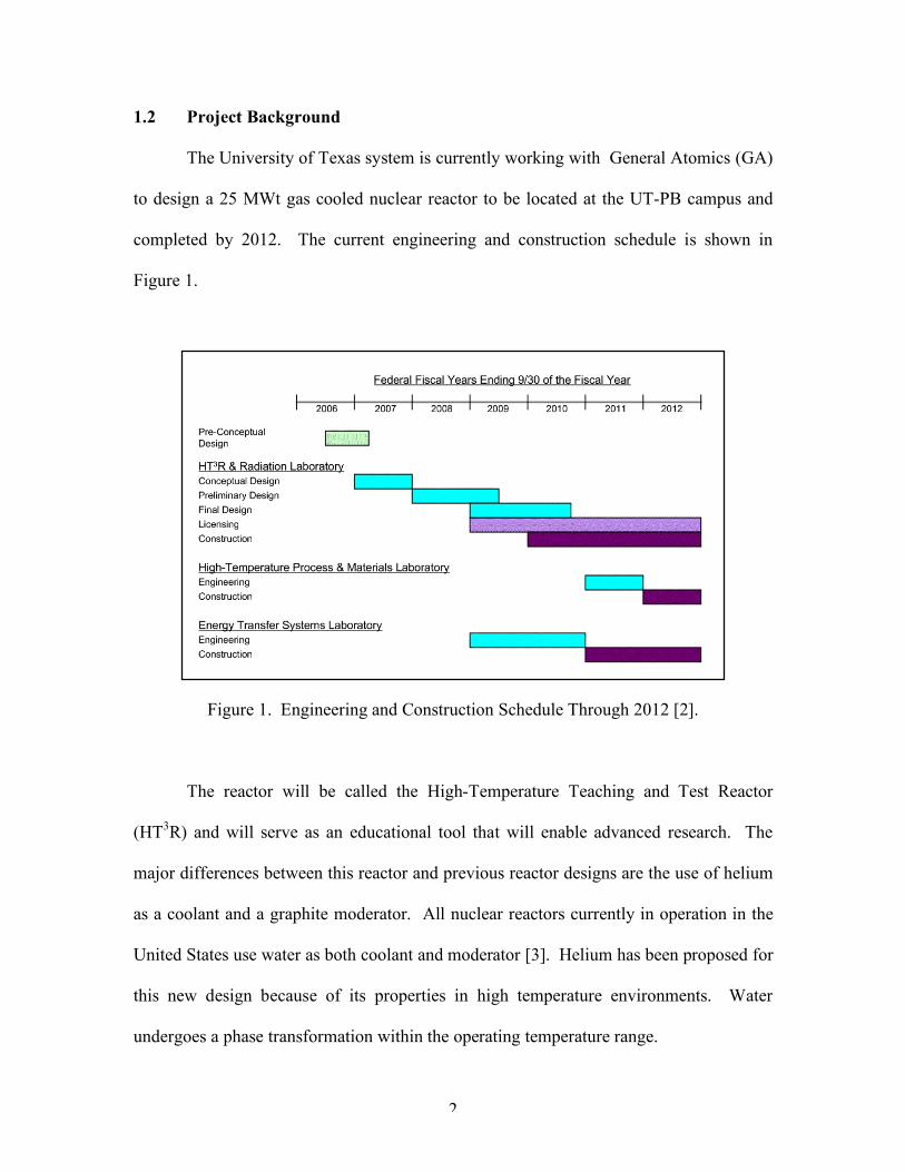
1.2 Project Background
The University of Texas system is currently working with General Atomics (GA)
to design a 25 MWt gas cooled nuclear reactor to be located at the UT-PB campus and
completed by 2012. The current engineering and construction schedule is shown in
Figure 1.
Figure 1. Engineering and Construction Schedule Through 2012 [2].
The reactor will be called the High-Temperature Teaching and Test Reactor
(HT3R) and will serve as an educational tool that will enable advanced research. The
major differences between this reactor and previous reactor designs are the use of helium
as a coolant and a graphite moderator. All nuclear reactors currently in operation in the
United States use water as both coolant and moderator [3]. Helium has been proposed for
this new design because of its properties in high temperature environments. Water
undergoes a phase transformation within the operating temperature range.

3
The HT3R will be used to perform leading research by utilizing the high
temperatures produced by the reactor. The focus of the research will include increasing
the efficiencies of nuclear-driven electricity production, the use of proliferation resistant
fuels, and developing high temperature refractory materials. The proposed reactor will
generate up to 25 MWt of heat that can be used in a number of on-site research
laboratories.
The facility will contain the reactor core, cooled by a closed loop of helium. The
helium will travel out of the reactor vessel into the primary heat exchanger (PHX). The
thermal energy from the reactor will be transferred to a secondary coolant loop composed
of pure nitrogen. The hot nitrogen will then pass into the laboratories for
experimentation and then be sent into the secondary heat exchanger (SHX). It is also
possible that the hot gas will be sent directly from the PHX to the SHX, bypassing the
laboratories. This will be the case when the reactor comes online because the labs will
not be completed at that time. In the SHX, ambient air will be used as a tertiary fluid to
cool the nitrogen to approximately 450ºC. The nitrogen gas will recirculate to the PHX,
while the air will exhaust to the environment.
One of the laboratories to be built in conjunction with the nuclear reactor is a
process heat lab that will be used to “test methods for desalinating water, making
synfuels, producing hydrogen, and other process heat applications” [4]. Another lab will
use the heated gas from the reactor to operate a Brayton cycle to test new power
generation methods. Current reactor designs typically run Rankine cycles. The Brayton
cycle provides a way to increase the overall efficiency of a power plant. Finally, a
radiation lab will be built to research radioactive materials and advanced nuclear fuel
4
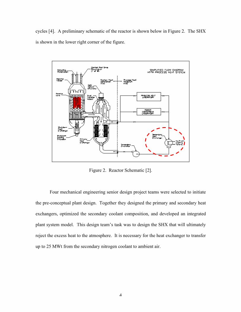
cycles [4]. A preliminary schematic of the reactor is shown below in Figure 2. The SHX
is shown in the lower right corner of the figure.
Figure 2. Reactor Schematic [2].
Four mechanical engineering senior design project teams were selected to initiate
the pre-conceptual plant design. Together they designed the primary and secondary heat
exchangers, optimized the secondary coolant composition, and developed an integrated
plant system model. This design team’s task was to design the SHX that will ultimately
reject the excess heat to the atmosphere. It is necessary for the heat exchanger to transfer
up to 25 MWt from the secondary nitrogen coolant to ambient air.

5
1.3 Problem Statement
The goal of this project is to develop a heat exchanger capable of rejecting the full
output of the HT3R reactor to the atmosphere.
1.4 Requirements
The initial requirements for our team were laid out in the UT-PB and General
Atomics information packet. A few of the requirements were deemed unnecessary and
after discussions with UT-PB and General Atomics, they were removed. Requirement
five was added during the course of the design process. The final requirements are listed
below in Table 1.
Table 1. Requirements [4].
Number Requirement 1 Must dissipate 25 MWt 2 Must be able to operate with an inlet temperature of 950ºC 3 Must be able operate at a pressure of at least 3.1 MPa on the hot gas side 4 Must “be able to withstand and/or mitigate the effects of inlet flow path
mal-distributions” 5 Primary gas inlet temperature must be 450oC 6 Must be a gas to gas heat exchanger. 7 Must “be able to maintain cooling capability through all anticipated
operational and design basis events”
1.5 Constraints
Our project faced constraints from several different sources. Since the heat will
be dumped directly into the environment, environmental regulations concerning
emissions, microbe formation and thermal exhaust were considered in the design. Cost
and schedule constraints were determined by UT-PB. Also, certain design parameters

6
such as the composition of the secondary gas and inlet and outlet temperatures have been
determined by the other groups involved in the project. This required all four groups to
coordinate and maintain open communication during the iterative design process.
Table 2. Constraints [4].
Number Constraint 1 Must meet environmental guidelines for heat dissipation 2 Material must withstand high temperature, possibly corrosive
environment 3 Water supply is limited in West Texas 4 Engineering cost of $150 million for entire reactor 5 Construction cost of $100 million for entire reactor 6 Able to implement by 2012 [2]
1.6 Deliverables
In addition to the heat exchanger specifications presented in this final report, the
design team has provided NETL, UT-PB, and GA with several items. A Solidworks
model of the SHX is included as a dimensional reference. A Simulink model has been
created to simulate the operation of the heat exchanger throughout the range of operating
conditions. Also, the design team has provided an estimate of the engineering and
construction cost and schedule.
1.7 Specification Sheet
A specification sheet, shown in Table 3, was created to aid the design process.
This sheet is divided into a requirements section and a constraints section. The functional
requirement is that the heat exchanger must be able to dissipate the entire amount of
thermal energy produced by the helium cooled reactor. This scenario would arise when

7
the reactor is running at full power and the labs are not in use. To prevent overheating of
the reactor, the entire energy output must be dissipated.
The constraints of the project include fluid, thermal, material, geometrical,
environmental, and service life constraints. Most of these constraints came directly from
UT-PB, such as the operating pressure and flow distribution of the gas. The geometric
and service life constraints are common design requirement for heat exchanger design
and life expectancies of power plant components [5]. The environmental constraint
pertains to the thermal exhaust of the heat exchanger. It is undesirable to have an exhaust
temperature that would be harmful to the local ecosystem. We were unable to find any
regulations that set limits on this exhaust temperature. In response, we included methods
for reducing the exhaust temperature, should the temperature need to be lowered.

8
Table 3. Specification Sheet.
Secondary System Heat Exchanger: Specification Sheet
D/W Functional Requirements/Constraints Functional Requirements
D Dissipate all thermal energy produced in reactor (up to
25MWt) Constraints Fluid D Flow distribution uncertainty of at least 10% D Operate at a pressure of at least 3.1 MPa on gas side W Pressure drop (nitrogen-side) <60 kPa W Pressure drop (air-side) <30 kPa W fluid velocity < 30 m/s Thermal D Operate with secondary inlet temp of at least 850oC D Reduce temp of N2 mixture by at least 400oC D Secondary side heat transfer correlation uncertainty >20% D Primary HX gas inlet must be 450oC Material D Material conductivity uncertainty of at least 10% Geometry
D Increased HX surface area to compensate for plugging
(10%) D Tube diameter (TEMA) range: .25"<d<2" Environmental
W Air exhaust from exchanger <450oC Quality D life expectancy of at least 20 years W life expectancy of at least 30 years

9
2 PATENT SEARCH
A search of the U.S. patent database was performed to gather ideas for heat
exchanger designs. The patents reviewed discuss methods for removing heat or for
improving the rate of heat removed from a hot fluid.
2.1 U.S. Patent 6,888,910: Methods and Apparatuses for Removing Thermal
Energy from a Nuclear Reactor
Heat produced from a nuclear reactor can be used throughout the system to power
turbines and research laboratories. The heat must be effectively transferred from the
reactor so that other systems can operate at maximum efficiency. The method of heat
removal from the reactor vessel is crucial to maintaining a working system.
Patent number 6,888,910 discusses different methods for removing thermal
energy from a nuclear reactor. The patent describes the methods in which heat can be
transferred from the reactor vessel to other gasses in the system. Heat pipes are discussed
as a possible solution for removing the thermal energy.
This patent discusses different methods of removing heat from a nuclear reactor.
As mentioned in the patent filing, heat pipes are one possibility for transferring the
thermal energy from a nuclear reactor core to a coolant fluid. As discussed later in this
report, our team investigated a number of heat removal systems, one of which was a heat
pipe. The discussion of heat pipes in this patent filing prompted the team to research the
possibility of their use in nuclear applications [6].
10
2.2 U.S. Patent 4,699,211: Segmental Baffle High Performance Shell and Tube
Heat Exchanger
Patent number 4,699,211 describes a baffle pattern in a shell and tube heat
exchanger. Baffles are used in the shell to direct the fluid over the tube bundle and are
also used to support the tubes in the tube bundle. The baffles block an area of the shell so
that the shell side fluid must pass through the open space of the baffle window. These
baffle windows occupy between 15-50% of the shell cross-sectional area. By alternating
the location of the baffle windows, the shell side fluid flow can be constantly redirected
over the tubes.
This particular patent describes a baffle pattern that rotates the location of the
baffle window by 90o for each baffle. This arrangement causes a helical fluid motion that
can increase the heat transfer by increasing shell side fluid turbulence. This design also
decreases the pressure drop of the shell side fluid in comparison with a more common
180o baffle rotation by slightly reducing the air path length. This reduces the amount of
friction felt by the air against the tube bundle [7].
2.3 U.S. Patent 4,483,392: Air to Air Heat Exchanger
Patent number 4,483,392 describes a type of air cooled heat exchanger.
According to the patent, hot process gas is passed into a series of small tubes. The tubes
cross over an air duct several times by making 180° turns at the ends. The tubes are
enclosed in a housing and a fan creates an air flow over the tubes. The passing air
convects the heat away from the surface of the tubes.

11
This design is conceptually similar to the air cooled heat exchangers that we
reviewed for our final design. The tube configuration would be instructive if it were
decided that the heat exchanger needed to be double pass rather than single pass. The
bends of the tubes are arranged to minimize the header size. Since the high temperature
alloy that will be used to construct the heat exchanger is very expensive, reducing the
amount of material required will be important [8].
Like the commercially available heat exchangers, the technology presented in the
patent does not meet our pressure requirements. The heat exchanger is only designed for
pressures up to 310 kPa. The high pressure and temperature requirements will make our
final design different from preexisting designs [9].

12
3 ALTERNATIVE DESIGNS
This section provides an overview of all the design solutions considered by the
project team. The different technologies are evaluated by several criteria. The major
criteria considered include temperature and pressure limitations, construction costs,
power requirements, and pressure drop. A complete list of contacted vendors is available
in Appendix C. Table 4 compares all the evaluated technologies.

13
Tabl
e 4:
Pro
pose
d So
lutio
ns.

14
3.1 Traditional Cooling Tower
Nuclear power plants currently in operation typically use water as their reactor
coolant. Because of this, wet cooling towers are a common method of removing waste
heat from the system. Steam leaves the reactor, moves through a Rankine power
generation cycle, and is then delivered to the cooling tower as hot water. A large scale
hyperbolic cooling tower is shown in Figure 3.
Figure 3. Hyperbolic Cooling Tower [10].
In this type of cooling tower, the hot water is sprayed from a high point in the
tower and allowed to fall to the bottom. As the water falls, it hits and is spread over fill
material. The purpose of the fill material is to break up the flow of the falling water and
increase the total wetted area. Fill is often made from corrugated PVC plastic [11].
Different types of fill are shown in Figure 4.

15
Figure 4. Fill Media [12].
Two modes of heat transfer occur in a cooling tower. One is convective heat
transfer from the hot water to the air. The other, more significant type of heat transfer is
the evaporation of a portion of the hot water. The heat absorbed in the evaporation of a
small percentage of the hot water results in a drop in temperature for the remaining body
of water. Evaporation of water consumes a large amount of heat and therefore, is an
effective way of removing heat from a system containing hot water [11].
Although a cooling tower system is a common way to remove heat from nuclear
reactors, there are several reasons why we have rejected it as a viable option. The
simplest reason is that one of our heat exchanger requirements mandated a gas to gas heat
exchanger. There are also design considerations that make water cooling a poor solution.
The HT3R will run loops of helium and nitrogen, but not water. Since water is not
part of the original system, the process becomes more complicated than simply piping hot
water from the reactor core to the cooling tower. Instead of being able to transfer the heat
from the hot nitrogen in the secondary loop directly to outside air, the heat would be
transferred first from the nitrogen into water, then from water to outside air. This would

16
result in an extra fluid loop that would include an additional heat exchanger, pump, and
piping.
An additional loop would also require extra maintenance and cleaning. For
cooling towers, cleaning is not a trivial matter. In 1993, there were three separate
outbreaks of Legionnaires’ Disease in the U.S. that killed three people. All three
outbreaks were traced back to microbes formed in improperly cleaned cooling towers
[13].
The lack of a large available water supply is another problem with using a water
cooling system. A large amount of water would be required initially to get the system
running. Makeup water would need to be added constantly to replace the evaporating
water [14]. Water would be a major investment in the startup and operating costs of the
reactor. Air can be pulled directly from the environment and has no acquisition cost. For
all these reasons, we have determined that a cooling tower is not an appropriate solution
to our heat exchange problem.
3.2 Heat Pipe
Another method of heat removal our team assessed was a system of heat pipes. A
heat pipe is a closed system that can be used to transfer heat from one area to another.
Heat pipes can transfer thermal energy at a very high rate and capacity with almost no
heat loss [15].
The design of a heat pipe is simple, consisting of a thermally conductive metal
tube filled with a coolant fluid. Fluids capable of operating in our temperature range are
sodium and lithium [16]. The fluid inside the tube is at both its saturation temperature

17
and pressure. When a section of the pipe is exposed to elevated temperatures the fluid
inside changes to the vapor state. The differences in density between the liquid and vapor
cause the two fluids to separate. The hot vapor moves to the other end of the heat pipe
where a tertiary fluid removes heat by convection from the outside of the tube. A
schematic of a heat pipe is depicted in Figure 5.
Figure 5. Heat Pipe Diagram [17].
The movement of the working fluid can be aided by the use of a wick and
capillary structure or an inclined orientation [15]. A wick and capillary structure allows
the condensed fluid to travel back to the hot side of the heat pipe. Raising one end of the
heat pipe would also allow the fluid to move from the hot to cold side based on the
change in density and elevation.
The operating temperatures range from 600 to 1200°C for sodium, and 1000 to
1800°C for lithium. Care must be taken to choose a working fluid that matches the
application for which it will be used. If a fluid’s saturation temperature and pressure are

18
too high for an application, there will be inadequate heat transfer because the fluid will
not evaporate.
Our team has decided that heat pipes are not a viable solution. The major
problem with using heat pipes is that the inlet temperature of the SHX is variable.
During the initial phases of the project, only the reactor and PHX will be in operation.
Our SHX must be capable of removing heat at an inlet temperature of 850ºC. When the
process heat laboratory and turbine lab are used, the fluid temperature the SHX receives
will be significantly lower. Heat pipes are not suited for this variable inlet temperature.
Solutions for this problem include having a modular system containing different
banks of heat pipes each with a different coolant. This would account for the different
temperature ranges that the SHX could experience. However, this solution is not viable
due to the large number and multiple types of heat pipes that would be required.
3.3 Radiative Heat Transfer
A more unconventional method of heat removal the team has considered is
radiative heat transfer. A radiative solution can take advantage of the fact that the fluid
temperature coming out of the core is much higher than the surrounding temperature.
Equation 3.1 governs radiative heat transfer.
)( 44
COLDHOT TTAQ !=•
"# (3.1)
The equation shows that the total heat transfer is proportional to the difference between
the two temperatures raised to the fourth power.
Conceptually, this setup would require a length of finned pipe. This setup would
lower the hot fluid temperature enough to avoid using high temperature alloys in the
19
SHX. Another stage of cooling would still be required to remove the remainder of the
heat.
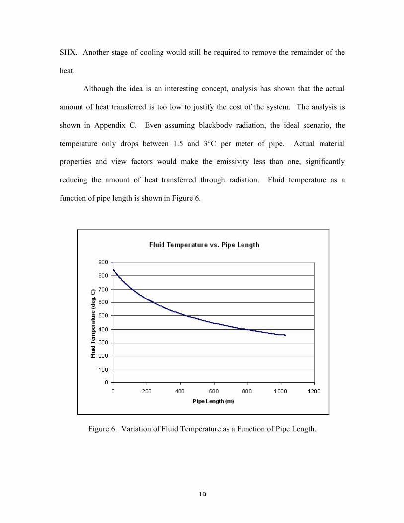
Although the idea is an interesting concept, analysis has shown that the actual
amount of heat transferred is too low to justify the cost of the system. The analysis is
shown in Appendix C. Even assuming blackbody radiation, the ideal scenario, the
temperature only drops between 1.5 and 3°C per meter of pipe. Actual material
properties and view factors would make the emissivity less than one, significantly
reducing the amount of heat transferred through radiation. Fluid temperature as a
function of pipe length is shown in Figure 6.
Figure 6. Variation of Fluid Temperature as a Function of Pipe Length.

20
Dropping the temperature into the range of standard alloys would require several
hundred meters of pipe. In addition to head loss and physical size concerns, the pipe’s
cost would be prohibitive. Currently, the System Team is tying to minimize the hot pipe
length because of the high cost of the high temperature alloy used to make the pipes [8].
Radiative heat transfer does not remove enough heat per meter of pipe to make the
system feasible.
3.4 Flat Plate Heat Exchanger
Consideration has been given to the flat plate heat exchanger due to its compact
and durable form. This well developed technology utilizes parallel corrugated or
embossed plates with flow channels to transfer heat from one fluid to another. The
spacing between each plate is nominally 4 mm. Typically, the hot and cold fluids enter
through inlet ports in each plate, flow through alternating channels, and exit through
outlet ports that lead to the next plate.
The flow channels are typically designed in a washboard pattern to promote fluid
turbulence and increase the overall heat transfer coefficient. Figure 7 shows the
corrugated plates in a flat plate exchanger.

21
Figure 7. Corrugated Plates [18].
A frame is constructed out of tightening bolts which hold the plates together and
gaskets which seal the perimeter from the atmosphere. While the tightening bolts allow
for easy access during maintenance and repair, the gaskets are known to fail under large
fluid pressures, causing leakage to the atmosphere [19].
In addition to failing under high pressures, the gasket material is also vulnerable
to high temperatures that could cause embrittlement or melting. For some applications,
the plates can be brazed together, eliminating the need for gaskets. These types of plate
heat exchangers can withstand pressures up to 3 MPa. However, this prevents
disassembly for maintenance. While brazed or welded plate heat exchangers can
withstand the high pressures of our specifications, the upper temperature limit is typically
around 300oC [18]. Our application, we will be using two gases with a large pressure
differential of 3 MPa. Flat plate heat exchangers are typically made from thin material to
reduce the overall size. The large pressure differential could cause the plates to deform,
constricting flow through the passages. For these reasons, we have decided against going
forward with a flat plate heat exchanger design.

22
3.5 Printed Circuit Heat Exchanger
The printed circuit heat exchanger (PCHE) is a newer technology that is being
used for the PHX. The main advantage to this type of heat exchanger is that it can
transfer the same amount of heat in a much smaller volume than other technologies, such
as flat plate heat exchangers. However, the printed circuit technology is expensive
because of the intricate manufacturing process. A Heatric PCHE is shown in Figure 8.
Figure 8. Heatric PCHE [20].
The PCHE is too delicate for our application. Unlike the PHX, the SHX will have
an open loop of unpressurized ambient air running through it. The 3 MPa pressure
differential between the flow channels could cause internal structural problems.
Additionally, the air will contain dust, water and other contaminants. The channel width
is on the order of a few millimeters [4]. If they become clogged, they will be extremely
difficult to clean. Even with a rigorous filtering system to remove air particles, the
humidity of the air would still be a problem. A dehumidifier would be needed to remove
water from the air. These components increase the cost of the system in terms of

23
equipment, maintenance, and pumping power. Internal stress concerns and the high level
of preconditioning the air would have to undergo have led us to rule out the PCHE.
3.6 Shell and Tube Heat Exchanger
A promising type of heat exchanger our team has considered is the shell and tube
heat exchanger. This design is the most common method of heat removal in industrial
applications.
3.6.1 Shell and Tube Configurations
Typical shell and tube heat exchangers are of three different classes: fixed tube-
sheet, U-tube, and floating head. The fixed tube-sheet type has tubes positioned into tube
sheets at either end that are welded to the shell. This eliminates the need for gaskets and
minimizes the required maintenance. An example of a fixed tube sheet can be seen in
Figure 9. This arrangement is optimal when thermal stresses are minimal and when
removal of the tube bundle is not required.
Figure 9. Fixed Tube-Sheet [5].
The U-tube arrangement uses bent tubes that are free to expand and are arranged
in a removable tube bundle as shown in Figure 10. This design requires gaskets around

24
the tube sheet and regular maintenance, however, individual tubes cannot be removed.
Therefore, when a tube fails it is necessary to plug the tube. This type of heat exchanger
is usually designed with extra tubes to compensate for plugging.
Figure 10. U-tube [5].
The floating heat exchanger, seen in Figure 11, consists of tubes supported by a
fixed tube sheet on one end that is welded to the shell and a “floating” tube sheet on the
other end that is allowed to move during thermal expansion of the tubes. The tube bundle
is removable and mechanical cleaning for pipe diameters larger than half an inch is
possible [5].
Figure 11. Floating Head [5].

25
The design of the shell and tube heat exchanger is just as its name implies: a shell
containing a coolant fluid is passed across a bank of tubes containing the hot fluid.
Different orientations of tubes can be arranged to achieve maximum heat transfer, as well
as meet geometrical constraints. When high pressures are involved, the high pressure
fluid is passed through the tubes, which are well suited to withstand the stresses. The low
pressure fluid typically passes through the shell side to prevent increased stresses on the
tube headers and baffles [5].
The most prevalent shell and tube designs are parallel and counter flow with the
latter providing a larger amount of heat transfer. This advantage is due to a larger
temperature gradient, the driving force behind heat transfer. The amount of tube surface
area can be increased by adding fins to the tubes. The fins improve heat transfer from the
hot fluid to the coolant. Multiple passes can be achieved by alternating the flow direction
through the tubes using sectioned headers. This increases the effectiveness and the
correction factor of the heat exchanger, however, it reduces the mass flow rate of the tube
side fluid [18]. One way to increase the number of passes without reducing the mass
flow rate is to connect multiple heat exchangers in series. In high temperature
applications, this allows the first exchanger to be designed with a high temperature alloy
and the subsequent heat exchangers to be made with a cheaper, more common material.
3.6.2 Shell and Tube Vendor Information
Our design uses pure nitrogen as the secondary fluid and ambient air as the
tertiary coolant. Due to the high temperature and pressure environment, standard
materials cannot be used to construct the heat exchanger. Alloys must be used that can

26
handle the thermal stresses and resist creep at these extreme conditions. Candidate alloys
include Incoloy 800H and Inconel 600. As mentioned above, multiple exchangers can be
arranged in series which would require only the first exchanger to be made of the high
temp alloy, reducing material costs.
All the vendors we spoke with were unable to work with the high temperatures
and pressures of our application. We did receive a response from Des Champs, which
designs the shell and tube exchanger seen in Figure 12 below. Their solution would
involve four heat exchangers in series, each being 1.8 m wide, 1.5 m tall and 4 m long.
This design would have a tube side pressure drop of 3.4 kPa and would cost between $1.8
to $2 million. However, for this design to work, the inlet gas pressure would have to be
reduced through an expansion valve from 3.1 MPa to about 138 kPa. This would require
a large compressor after the SHX to increase the pressure to 3.1 MPa [21]. The pressure
reduction is not appealing because of the large amount of electricity required to
repressurize the nitrogen to 3.1 MPa.
Figure 12. Des Champs Thermo-T Shell and Tube Heat Exchanger [22].

27
In order to use the ambient air as a tertiary fluid that passes through the shell side,
it will be necessary to include a blower to overcome the pressure drop and achieve the
desired flow rate. A filtering system will also be necessary to remove dust particles from
the air flow. There are no prohibitive obstacles to using the shell and tube heat exchanger
in the SHX design. A full design analysis is included in Section 4.1.
3.7 Air Cooled Heat Exchanger
The air cooled heat exchanger (ACHE) is currently the most promising
technology for meeting our requirements. This section will cover background about the
ACHE and vendor information.
3.7.1 ACHE Design and Operation
The ACHE is constructed differently than the shell and tube heat exchanger. The
major difference is that, for the ACHE, the shell flow is replaced by a fan-driven air duct
[23]. Since the ACHE is specifically designed to use air as its coolant fluid, it performs
well under the given requirements and constraints. A schematic of the ACHE is shown
below in Figure 13.

28
Figure 13. ACHE Operation [24].
The ACHE is composed of a bundle of finned tubes that are connected to
rectangular box headers at both ends. The front headers are welded boxes that divide the
flow between the pipe and the tube bundle. The rear headers redirect the flow from one
tube pass to another. The heat transfer is driven by convection between the tube bundle
and ambient air. This process is enhanced by fans which increase the mass flow rate of
the air [23].
The fans can be placed above or below the tube bundle. These systems are called
induced draft and forced draft, respectively. The forced and induced draft configurations
are shown in Figures 14 and 15.

29
Figure 14. Forced Draft ACHE [24].
Figure 15. Induced Draft ACHE [24].
The forced draft setup is the best for our operating conditions. This is because
forced draft fans are placed below the pipes, not in the hot stream of exhaust air. If the
fans are placed in the hot stream of air, thermal stresses can be a problem. In addition,
forced draft systems are easier to manufacture and maintain [23]. The main advantage of
the induced draft system is that it prevents the possibility of warm air recirculation.
Warm air recirculation occurs when the fans draw in hot air that has been exhausted [24].
30
3.7.2 ACHE Vendor Information
Ecodyne MRM has provided our team with a basic quote and schematic for a two-
unit ACHE that would be coupled with a recuperator. The use of a recuperator is
discussed in Section 3.8. Based on the specifications and operating parameters we
provided, Ecodyne MRM quoted a system price of $506,800. The ACHE is designed to
cool a 43 kg/sec flow of the secondary coolant fluid from 450ºC to 50ºC by rejecting 22
MWt. The unit contains two coolers, with two 30 kW fans per cooler [25]. Each cooler
utilizes 411 tubes made from 304 SS.
The capital required for this ACHE is well within reason, but it must be noted that
a recuperator will be required to use this system. If this option is pursued, a high
temperature recuperator with subsequent piping and valves will be required, dramatically
increasing the cost of this option.
Ecodyne MRM and other vendors were unwilling to provide a product quote that
would satisfy the high temperature requirements for a heat exchanger with an inlet of
850oC. A design for a high temperature heat exchanger would be different from the
standard products provided by vendors. Normally, fins are embedded on the tubes to aid
in the heat transfer. The temperatures for our application are too high to permit the use of
standard materials used to construct the fins, so bare tubes of a high temperature alloy
must be used [25].
3.8 Recuperator
A recuperator is essentially a heat exchanger placed in a system to transfer heat
from a hot flow to a cold flow in a closed loop. Typically, recuperators are used in power

31
generation plants to transfer heat from turbine exhaust to the fluid entering the
compressor. The recuperator helps increase the fluid’s temperature as it enters the
compressor and reduces waste heat.
For the design of the SHX, we considered placing a recuperator before the heat
exchanger in order to drop the temperature of the nitrogen at the inlet of the SHX. This
drop in temperature allows the heat exchanger to be constructed of common materials
instead of costly high temperature alloys. This also allows the circulator to be located on
the cold side, reducing its material costs. In addition, using a recuperator decreases the
amount of high temperature piping necessary. A schematic of the setup can be seen in
Figure 16.
Figure 16. Schematic with Recuperator.
While the recuperator allows the SHX to be constructed from lower temperature
alloys, the recuperator itself must be able to withstand the 850°C inlet temperature. This
is done by constructing the recuperator out of a high temperature alloy, which essentially
transfers the bulk of the cost and technical difficulty from the SHX to the recuperator. In
addition, most recuperators are of the shell and tube design and pass the high pressure
PHX
Recuperator
SHX
air
850 C
450 C
450 C
50 C

32
fluid through the tubes and the low pressure fluid through the shell. The circular design
of the tubes is able to withstand the high pressures without generating high stresses.
However, for our application, the same high pressure fluid is passing through both sides
of the exchanger. This makes the design of the shell more complicated since the effects
of high pressure effects on baffles, tube sheets, sealing strips and headers must be
considered. A Heatric heat exchanger would be well suited for this application. This
design would be able to handle the high temperatures and high pressures of the nitrogen
gas.
While a Heatric exchanger would be the best model for the recuperator, we have
determined that the design of the secondary heat removal system would be better without
a recuperator. The recuperator adds to the complexity of the system increasing the
amount of maintenance required. Additionally, the pressure drop on the hot gas side and
the operating cost of the circulator to overcome this pressure drop would increase. Also,
the price Heatric quoted for the PHX was $7 million. The recuperator and PHX would be
transferring similar amounts of heat, so the prices are likely to be similar. $7 million is
more than the amount estimated for the entire SHX system in our final recommended
design.

33
4 PROJECT SOLUTION
We were unable to find a vendor who could provide our team with a high
temperature and pressure heat exchanger. Therefore, designs of the two most promising
heat exchangers, the shell and tube and air cooled, were created using programs written in
Matlab.
4.1 Shell and Tube Design
The inlet temperatures, heat rate and mass flow rates are parameters that are
initially known. The exit temperatures can be found from the heat rate equation (Eq.
4.1).
)( chP TTCmQ !""= && (4.1)
Once the exit temperatures are known the log mean temperature difference (Eq. 4.2) can
be found.
!
"Tlm
=(Thi #Tco) # (Tho#Tci)
ln(Thi #Tco)
(Tho #Tci)
(4.2)
The correction factor is found by calculating the thermal effectiveness (Eq. 4.3) and the
heat capacity ratio (Eq. 4.4) and referring to a correction factor chart [5].
ThiTci
ThoThiP
!
!= (4.3)
TciTco
ThoThiR
!
!= (4.4)
34
In the program, the overall heat transfer coefficient is initially set at 110 W/m-K, a
typical value for heat exchangers. The required surface area of the heat exchanger can
then be found from equation 4.5.
lmTUF
QA
!=
&
(4.5)
Once the initial area of the heat exchanger has been determined, the initial
geometry of the exchanger can be set. The outer diameter and thickness of the tubes was
set to standard TEMA sizes (19 mm and 3.01mm) and the length and number of tubes
were set to achieve the desired surface area for heat transfer [5]. The number of tubes
affects the velocity of the fluid flowing through the pipes. An increase in the number of
tubes reduces the velocity, which decreases the overall heat transfer coefficient. An
increase in the pipe length increases the pressure drop across the tubes. Therefore, there
is a tradeoff between achieving the highest overall heat transfer coefficient and
minimizing the pressure drop. Once the optimum number and length of tubes is
determined, the overall heat transfer coefficient to be found (Eq. 4.6).
1
1
21ln
11!
""#
$%%&
'""#
$%%&
'("#
$%&
'+""#
$%%&
'+""#
$%%&
'=
r
r
k
r
hhU
io
(4.6)
This value is a function of the internal and external convection coefficients, the thermal
conductivity of the tube wall and the internal and external fouling coefficients. The hot
nitrogen gas is a relatively clean fluid in a closed loop and therefore internal fouling
should be negligible [5]. The external fouling is also neglected because the dusty air will
be filtered before passing over the tube bundle.
After multiple iterations, we reached a design that satisfied our requirements. Our
shell and tube design has the parameters listed in Table 5.

35
Table 5. Shell and Tube Properties.
Fluid Properties Exchanger Geometry per Module
Tube Side
Shell Side Number of tubes 830
Inlet temp (oC) 850 50 Tube outer diameter (mm) 19.05 Outlet temp (oC) 453 352 Tube inner diameter(mm) 12.7 Mass flow (kg/sec) 55 80 Tube length (m) 3.048 Pressure (kPa) 3100 101.5 Baffle window (%) 15 Pressure drop (kPa) 55 22 Baffle spacing (m) 0.3048
The heat exchanger is a four module design that has a single shell pass and a double tube
pass. The gas is divided into 415 tubes per pass, each tube having an outer diameter of
19.05 mm and a wall thickness of 3.18 mm. Therefore, each module has a total of 830
tubes that are slightly over 3 m in length. The shell that houses the tube bundle has a
diameter of 1.5 m.
The hot gas inlet leads to a front header that distributes the flow through the pipes.
The flow then passes through the top half of the tube bundle and into the rear header,
which channels the flow into the lower half of the tube bundle. The gas path is
represented by the arrow in Figure 17. The gas then flows into the lower half of the front
header, and into the inlet of the next module. The air enters the shell and flows across the
tubes. The air path is represented by the arrow in Figure 18. Alternating baffles increase
the turbulence of the air and creates cross flow and counter flow patterns.

36
Figure 17. Nitrogen Gas Path through Shell and Tube HX.
Figure 18: Air Path through Shell and Tube HX.
For easy maintenance, a floating head assembly is recommended. This means
that the front header would be rigid against the shell while the rear header is free to move
to accommodate the thermal expansion of the tube bundle. The TEMA designation for

37
this exchanger is “AEP”. AEP indicates the gas inlet header is channel type (TEMA: A)
with removable cover for easy tube access. The shell is a one pass shell (TEMA: E) and
the rear head is an outside packed floating header (TEMA: P) that will accommodate
expansion of the tube bundle [5].
The team design of the shell and tube heat exchanger has an overall heat transfer
coefficient of 102 W/m-K. Typical values for our application are between 50 and 200
W/m-K. A larger heat transfer coefficient is preferred because less area would be
required. However, our exchanger had a pressure drop on the tube side of 55 kPa which
approaches the self imposed upper limit in the specification sheet. This overall heat
transfer coefficient is strongly linked to the baffle window, the amount of area not
blocked by the baffle. The relationship can be seen in Figure 19.
Figure 19. Baffle Window Effect on Overall Heat Transfer Coefficient.

38
The shell and tube design has a baffle window of 15%, which is the lower limit
suggested by TEMA. Smaller windows reduce the area available for shell side flow and
result in large increases in shell side pressure drop [5]. A baffle window of 50% is the
practical upper limit. There is a limit because the baffles have holes through which the
tubes pass. The baffles act as structural supports. For baffle clearances greater than 50%,
the tubes in the middle of the tube bundle are unsupported. This leads to sagging of the
tubes.
The pressure drop through the tubes consists of three separate components: the
pressure loss due to the headers, the pipes, and elevation change (4.7).
EPHTPPPP !+!+!=! (4.7)
The pressure drop due to the elevation change is negligible compared to the other two
terms, and was therefore neglected. The pressure drop in the pipes is a function of the
friction factor, tube length, tube inner diameter, fluid velocity through the tubes, number
of tube passes, and the expansion and contraction loss coefficients. The friction factor is
a function of Reynolds number and relative roughness of the pipe and can be found using
the Moody Chart [27]. The pressure drop is due to the sudden contraction and expansion
of the flow channel and is a function of the mass velocity, density of fluid, number of
passes, the contraction and expansion loss coefficients and acceleration due to gravity [5].
The contraction and expansion coefficients come from charts that relate the ratio of the
cross-sectional areas of the tube and the header [27]. The following pressure drop
equation accounts for all these factors:
Ptc
i
t
pt
TT NKK
d
fL
Ng
GP !
""#
$
%%&
'++++=( 4
5.1
2
2
) (4.8)

39
For the shell side, the pressure drop is the sum of the pressure drop across the tube
bundle, the drop in the baffle windows, and the drop in the entrance and exit regions
(4.9).
sb
tcc
tcw
ibWBBibBSRR
N
NPRPNRPNP !!+"+!"!+!"#=" )1)((2]))(1[( ,1, (4.9)
Equation 4.9 is a function of the number of baffles, the correction factors for the baffle,
shell and baffle leakage, number of tubes in the baffle window and in the internal cross
flow section.
Using these equations, it was determined that the pressure drop was 55 kPa
through the tubes and 22 kPa through the shell. The power required to overcome the 55
kPa pressure drop is found using Equation 4.10 and is calculated to be 270 kW.
Pm
W !="
&& (4.10)
The same calculation is performed on the shell side with a pressure drop of 22
kPa. The power requirement was determined to be 1.6 MW to overcome the pressure
drop. This is a large value compared to the tube power requirement due to the large mass
flow rate and low density of air at ambient temperature.
If this system runs for eight hours a day and the cost of electricity is $.08/kWh,
the shell and tube design would cost $1197 per day to operate. This estimate assumes the
heat exchanger is dissipating the entire 25 MWt and that the fans are 100% efficient.
4.2 ACHE design
An air cooled heat exchanger was designed that could satisfy the high
temperatures and pressures of our application. The design process is similar to the design

40
of the way the shell and tube exchanger was designed. An initial overall heat transfer
coefficient must be assumed to solve for an initial area. The geometrical features of the
exchanger are then set and a new overall heat transfer coefficient is calculated. This
iterative process follows the same methodology as the shell and tube, except that instead
of shell side considerations, it was necessary to design for the air flow over the tubes.
This facet involved designing the tube bundle geometry and the air ducts that direct flow
over the tube bundle. For our design, we chose to make our exchanger a two bay unit
similar to the Ecodyne design. A connecting section of pipe guides the flow from the
outlet of one bay into the inlet of the second bay. This two bay design is meant to keep
the exchanger from being too long in one direction, which would lead to tube
manufacturing problems.
This heat exchanger will need to drop the gas temperature by 400oC, the same
temperature difference as the original Ecodyne design but at a higher gas inlet
temperature (850oC instead of 450oC). Because the heat rate equation is dependant on
the temperature difference and not the actual temperatures, it was decided to make our
design similar to the Ecodyne design. Our design does include a few modifications to
accommodate the higher temperature. First, the tubes would have to be made out of a
high temperature alloy instead of the stainless steel used by Ecodyne. Also, the Ecodyne
tubes had embedded aluminum fins which would not be suitable for the high temperature
design. Therefore, bare tubes are used, which require an increase in the tube length or
number to account for the extra heat transfer surface area. The computer model used to
create this design is discussed further in Section 5.

41
The team-designed ACHE has the properties shown in Table 6. This design uses
410 Inconel tubes per bay, for a total of 820 tubes. The heat exchanger will reduce the
hot gas temperature from 850oC to 437oC and will raise the temperature of the air passing
over the tubes from 50oC to 352oC. This is done with four fans that will be blowing air
over the tube bundle at a speed of about 20 m/s.
Table 6. ACHE Properties.
Fluid Properties Exchanger Geometry per Bay Tube
Side Air
Side Number of tubes 410 Inlet temp (oC) 850 50 Tube outer diameter (mm) 19.05 Outlet temp (oC) 437 352 Tube inner diameter(mm) 12.7 Mass flow (kg/sec)
55 80 Tube length (m) 12.5
Pressure (kPa) 3100 101.5
The pressure drop through the tubes was calculated using the same method as
with the shell and tube. The air side pressure drop is a function of mass velocity of the
air, the density of the air at the inlet and outlet, the tube layout, friction factor, and free
flow area (Eq. 4.11). The calculated pressure drop through the tubes is 47 kPa and 2.13
kPa over the tube bundle.
!!"
#
$$%
&''+(+
'=)
m
i
frto
i
i A
Vf
GP
*
*
+
,
*
*+
*)1)(1(
2
22
(4.11)
The power required to overcome the pressure drop is 226 kW in the tube bundle
and 228 kW for the air flowing over the tube bundle. If this system runs for 8 hours a
day and the cost of electricity is $.08/kWh, the ACHE design would cost $291 per day to
operate. This is assuming the exchanger is dissipating the entire 25 MWt and that the

42
fans are 100% efficient. This design yields an overall heat transfer coefficient of 126
W/m-k.
4.3 Design Comparison
A comparison of the two models shows that the ACHE outperforms the shell and
tube design for each metric considered. Table 7 compares properties of the two designs.
Table 7: Heat Exchanger Model Comparison.
Metrics Shell and Tube Air Cooled HX Overall Heat Transfer Coefficient (W/m-K) 102 126 Fluid Pressure Drop (kPa) 55 47 Air Pressure Drop (kPa) 22 2.13 Operating Cost ($/day) 1,197 291 Maintenance - +
The overall heat transfer coefficient for the ACHE is 20% higher than the shell
and tube design. This relates to the ability of the heat exchanger to remove heat from the
hot fluid. The ACHE has lower pressure drops through both the fluid and air sides. The
hot fluid flowing through the shell and tube goes through 25 m of pipe and the flow is
redirected due to the headers. The cold side flows through the shell and changes
directions multiple times due to the baffles. This increases the number of times the same
air passes over the tube bundles, increasing the head loss. The hot flow in the ACHE has
25 m of pipe and one channel to redirect its flow. The cold air passes only once through
the tube bundle.
The heat transfer coefficient is approximately 20% higher for the ACHE than for
the shell and tube heat exchanger. This increase in the overall heat transfer coefficient is

43
due to the larger air side convection coefficient for the ACHE: 133 W/m-K for the ACHE
compared to 105 W/m-K for the shell and tube. The larger heat transfer coefficient can
be attributed to fresh air constantly being blown over the tube bundle. In contrast, the
shell and tube passes the same air through each module.
The pressure drop directly relates to the operating cost by the amount of power
required to overcome this drop (Eq. 4.10). Because the shell and tube has a higher
pressure drop, the operating costs are also higher. The ACHE is easier to maintain
because only the top cover needs to be removed to access the tube bundle. This allows a
pressure washer to be used to clean the tube bundles. Cleaning the shell and tube setup
would require opening the shell for all four modules. The tube bundles would then have
to be removed before cleaning. In addition, the shell interior and the baffles would also
have to be cleaned. The ACHE outperformed the shell and tube for each metric and is
therefore the preferred design.
4.4 Economic Analysis
The cost of the high temperature ACHE is estimated to be between $2.1 and $6.4
million. This amount was calculated by using the Ecodyne quote of $506,800 and
multiplying by the cost ratio between stainless steel and Inconel 600 pipe [25]. The two
quotes we received for Inconel pipe were $29 and $88 per foot. Stainless steel (304SS)
was quoted at $7 per foot by both vendors [8, 28]. The two Inconel quotes give cost
ratios of 4.1 and 12.6, respectively. The two ratios are then multiplied with the base cost
of $506,800 to get a cost range of $2.1 and $6.4 million.

44
The engineering and construction schedule were also based on the Ecodyne quote.
Ecodyne estimated four to eight weeks for engineering design [25]. The high
temperature material requirement makes the design nonstandard. Therefore, we
increased the length of engineering time to eight to twelve weeks. The construction
schedule also needed to be lengthened from the eighteen to twenty weeks quoted in the
Ecodyne response. One of the Inconel pipe manufacturers we contacted quoted fifteen
weeks for fabrication of the pipes [28]. The extra time for fabrication of Inconel parts led
us to increase the construction schedule to 32 to 40 weeks.

45
5 COMPUTER MODELS
Our team has developed two computer models for the SHX system. First, a
mathematical model of the SHX has been created in Simulink. This model has been
incorporated into the full system Simulink model created by the System Team.
The other model created is a basic scale representation of the SHX in Solidworks.
The model is being used for plant layout purposes by the System Team.
5.1 Heat Exchanger Simulation
Simulink is a powerful, object oriented programming tool similar to Labview that
can run inherent and user-defined Matlab codes. A Simulink model was created that
combines the effects of each group’s system components and allows a user to quickly
view the behavior of the overall system in response to changing operating parameters.
From the SHX’s standpoint, it is necessary to accept the hot gas inlet temperature and
pressure as well as mass flow rate and return the outlet temperature, pressure and mass
flow rate. This was done using an embedded Matlab function and can be seen below in
Figure 20.
46
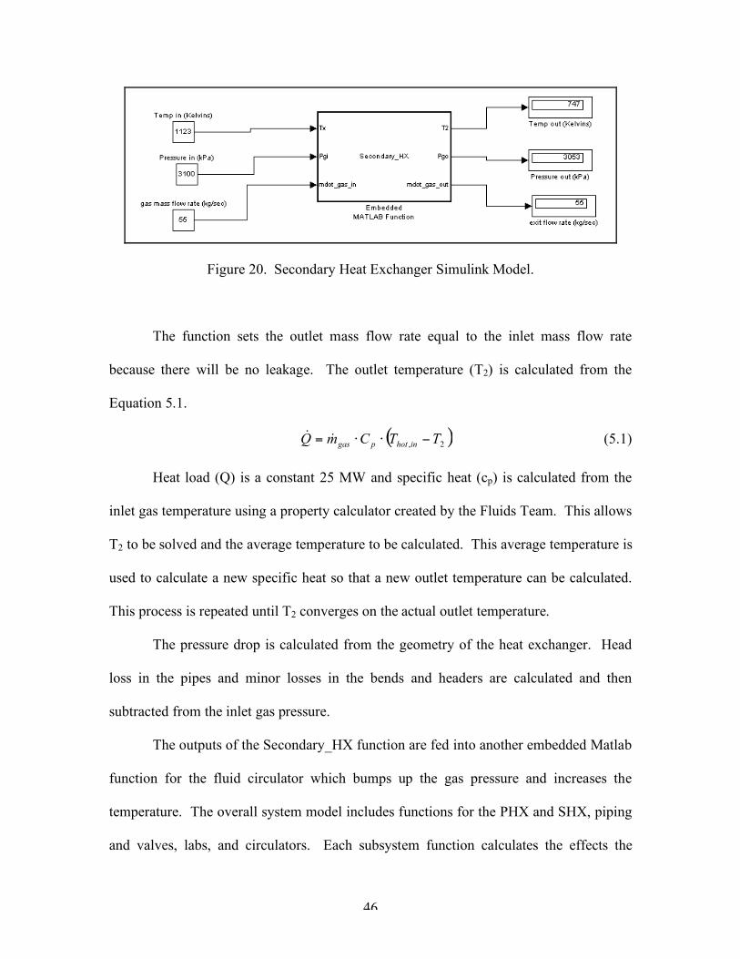
Figure 20. Secondary Heat Exchanger Simulink Model.
The function sets the outlet mass flow rate equal to the inlet mass flow rate
because there will be no leakage. The outlet temperature (T2) is calculated from the
Equation 5.1.
( )2,TTCmQ inhotpgas !""= && (5.1)
Heat load (Q) is a constant 25 MW and specific heat (cp) is calculated from the
inlet gas temperature using a property calculator created by the Fluids Team. This allows
T2 to be solved and the average temperature to be calculated. This average temperature is
used to calculate a new specific heat so that a new outlet temperature can be calculated.
This process is repeated until T2 converges on the actual outlet temperature.
The pressure drop is calculated from the geometry of the heat exchanger. Head
loss in the pipes and minor losses in the bends and headers are calculated and then
subtracted from the inlet gas pressure.
The outputs of the Secondary_HX function are fed into another embedded Matlab
function for the fluid circulator which bumps up the gas pressure and increases the
temperature. The overall system model includes functions for the PHX and SHX, piping
and valves, labs, and circulators. Each subsystem function calculates the effects the
47
subsystem would have on the secondary fluid and passes the new values on to the next
component. When combined, the functions create a powerful system representation that
allows the user to vary operating parameters and observe the effects on the fluid and
overall system. To verify the results of the SHX Simulink model, a simulation was run
which varies the model inputs so that a comparison of the output trends can be
performed. These results can be seen in Appendix E.
5.2 Matlab Codes
In addition to creating the SHX design in Matlab, we also had several supporting
codes that were important in completing the design. These codes include a mass flow
analysis and a required area calculator. The Matlab code can be seen in Appendix E.
5.2.1 Mass Flow Analysis
The Matlab script mass_flow_analysis.m was created to observe the dependence
of the outlet temperature of the fluid to the mass flow rate. The heat load and inlet
temperature of the fluid is specified as 25 MWt and 850oC and 52oC for the gas and air
side respectively. The outlet temperatures are solved for the range of mass flow rates. A
graph of this relation and can be seen in Figure 21.

48
20 30 40 50 60 70 80-400
-300
-200
-100
0
100
200
300
400
500
600
mass flow rate of gas (kg/sec)
gas outlet temperature (Celcius)
mass flow analysis of hot gas
20 40 60 80 100 120
200
300
400
500
600
700
800
900
1000
1100
mass flow rate of air (kg/sec)
air outlet temperature (Celcius)
mass flow analysis of air coolant
Figure 21. Dependence of Outlet Temperature on Mass Flow Rate.
The PHX Team has determined that they need the SHX to drop the temperature of
the gas to a constant 450oC. This corresponds to a gas mass flow rate of 55 kg/sec. This
flow rate is believed to be high enough to run the turbine in the Brayton cycle lab [29].
For the air side, it is desirable to reduce the outlet temperature of the exhausted air
as much as possible. A mass flow rate of 80 kg/sec was chosen which corresponds to an
exhaust temperature of 352oC. Several vendors were contacted and it was determined
that this flow rate, while relatively high, is possible at the expense of increased power
consumption in the fans.
5.2.2 Gas Calculator
The Fluids Team created a Matlab script that calculated relevant thermodynamic
properties of air. It is necessary to input a temperature and pressure for the fluid and to
specify whether the fluid is air or nitrogen. The script then outputs the specific heat,
viscosity, density, and thermal conductivity. This code was used throughout the
development of the heat exchanger models.

49
5.3 Solid Modeling
A Solidworks model of the selected design is one of the deliverables of this
project. The model will be incorporated into the System Team’s layout of the entire
plant. The plant model will be useful in understanding what the finished plant will look
like. It can also be used as a marketing tool while additional funds are being raised for
the project.
As stated earlier, the only specific design information we received came from
Ecodyne MRM. Figure 22 shows the engineering drawing received from Ecodyne.
Figure 22. Ecodyne Air Cooled Heat Exchanger [30].
The dimensional information provided by this drawing is limited to two of the three outer
dimensions. However, by using the given dimensions to create a scale for the drawing,
other pertinent dimensions were measured. From these measurements a representative
Solidworks model was constructed. This model is shown in Figure 23 and specified
dimensions are in meters.

50
Figure 23. Solidworks Model of Ecodyne Design.
Since we determined that a shell and tube system could be used as a solution, we
decided to make a solid model of that system as well. This model is based on the design
discussed in Section 4.1. The solid model is shown in Figure 24 and the specified
dimensions are in meters.

51
Figure 24. Shell and Tube Solidworks Model.

52
6 RECOMMENDATIONS AND CONCLUSIONS
The major problem our team has faced has not been the design of the heat
exchanger, but with the materials that are required to withstand the extreme operating
environment. The air cooled heat exchanger system that our team is recommending is
standard in industrial practices, but the temperatures and pressures are not.
Our team has had difficulty contacting vendors willing to provide heat exchangers
that meet our specifications. Vendors have expressed difficulty in designing heat
exchangers to meet both high temperatures and pressures, but have offered quotes for
systems that meet one of those two requirements. By separating the design process from
the manufacturing process, there is a greater chance of finding companies capable of
working on this project.
It is our team’s recommendation that an engineering firm be contracted to perform
a complete design of an air cooled heat exchanger. The specifications we have provided
will allow an engineering company to design to the requirements and constraints of this
application. The design that is produced from the engineering company can then be sent
to a manufacturing facility for construction. If the manufacturer is presented with a
design that has been verified as safe and effective, they need only be concerned with how
to build it.
6.1 Future Design Recommendations
The following sub-sections cover important design issues that should be
developed further. These issues include a control system to ensure the gas exit

53
temperature from the SHX is 450oC, dual materials to lower the cost of the exchanger,
environmental regulations concerning the hot exhaust temperature, and the possibility of
fouling and clogging from using unfiltered air as a coolant.
6.1.1 Gas Exit Temperature Control System
The design of the PHX requires a fixed fluid inlet temperature to achieve its
desired outlet temperature. Consequently, a control system will be needed to be
implemented to keep the outlet temperature of the SHX at a constant temperature of
450°C.
A system to control the outlet temperature for an ACHE can be implemented
simply. When the inlet temperature of the SHX is less than the maximum of 850°C, the
speed of the fans can be reduced to achieve the desired outlet temperature. Reducing the
fan speed lowers the mass flow rate of the air, which in turn lowers the total amount of
heat transferred. Temperature sensors would need to be placed in the main fluid line after
the lab flows have joined back together. This system can be automated so that fan speed
is automatically controlled by the inlet temperature.
Another part of the control system would cover the case when the labs are using
all or nearly all of the heat produced by the reactor. If the fluid temperature exiting the
labs was near 450°C, the SHX would remove too much heat. This would be the case
even if the fans were turned off because of natural convection through the fan ducts.
There are two solutions to this problem. The first solution would be to add a pipe
for the fluid to flow through which would bypass the SHX. A valve to direct the flow
into the bypass pipe would be activated when the lab outlet temperature dropped below a

54
set value. The other method to minimize the heat loss in the SHX would be to put duct
covers on top of the AHCE air ducts. The lids would eliminate natural convection
through the ducts. With the covers in place, the tube bundle would be fairly well
insulated. Further analysis needs to be conducted to determine which system would be
better suited for the HT3R.
Once a control system is chosen, guidelines should be created for the labs to place
lower limit on their fluid outlet temperature. The change in temperature resulting from
the bypass system would be added to 450°C. This higher temperature would be the
minimum allowable lab outlet temperature. The temperature sensors in the lab outlet
pipe would be able to signal lab operators when they are approaching this limit.
It is important to point out that controlling the PHX inlet temperature is necessary
in maintaining ideal operating conditions for the labs, not in preventing a system
breakdown. If the PHX inlet temperature was allowed to drop below 450°C, the result
would be a PHX outlet temperature of less than 850°C. The labs would not receive the
hottest possible fluid. If this became a problem, the labs would need to lower the power
demands on the fluid loop to allow it to heat back up to the maximum temperature.
6.1.2 Dual Material ACHE
The cost of Inconel 600 for the tube bundles is much more expensive than a
regular alloy used for low temperature operation. The price of Inconel 600 ranges from
$29/ft to $88/ft based on the piping vendors we contacted [8, 28]. On the contrary, the
stainless steel (304SS) used in the low temperature designs costs $7/ft [28]. To reduce
the cost, the tubing could be divided into two stages composed of different alloys, one for

55
high temperatures and one for low temperatures. The high temperature section would
still be constructed of Inconel, but the low temperature section could be made out of a
standard alloy, such as stainless steel. The temperature of the nitrogen gas would need to
be lowered to 750ºC to 800ºC, according to a conversation with a vendor from Heatric
[26]. Using dual materials has the potential to dramatically reduce the overall cost of the
ACHE, while retaining its heat transfer capability.
While this design is worth further consideration, it must be noted that there are
safety concerns associated with using two different alloys. If the high temperature
section of tubes failed to reduce the temperature to 750ºC, the stainless steel tubes would
experience temperatures above their operational range. The stainless steel tubes could be
damaged. We believe that this concern can be adequately addressed, because the entire
plant is designed on the assumption that the SHX will be able to remove its required heat
load. The reactor would need to be shut down immediately if the SHX stopped operating
for some reason.
6.1.3 Air Exhaust Temperature
The high temperature of the exhaust air from the SHX is a concern because of its
potential impact on the environment. The team design of both the shell and tube and air
cooled heat exchanger produces an air outlet temperature of about 352°C. We were not
able to find relevant thermal exhaust regulations to use in our design. We searched the
websites of the NRC and the EPA. The NRC was contacted by phone and by email as
well, without a response. All the literature we were able to find concerned thermal
pollution in bodies of water.

56
If the design outlet temperature proves to be too hot, there are two methods by
which the temperature can be lowered. The first way to lower the temperature is to
increase the mass flow rate of the air as it flows over the tube bundle. However, this
would increase the power requirement of the fans. The other option is to mix the exhaust
air with additional ambient air. This could be accomplished by using a cooling stack.
6.1.4 Air Filtration
Dust particles present in the ambient air pose a problem with the shell and tube
heat exchangers. The heat exchanger shell contains many tubes. As ambient air flows
through the shell, dust and debris may deposit within the baffles and spacing between
tubes. As debris builds up, fouling resistance increases, reducing the amount of heat
transfer from the nitrogen to the air.
Cleaning the outside of the tubes requires removing the headers from the end of
the shell. The shell can then be separated to expose the tube bundle. From here,
individual tubes can be pulled out for cleaning [5]. While this appears to be a relatively
straight forward process, performing this task routinely for four shell and tube units
would be time consuming.
If the shell and tube design were to be pursued, an air filtration system would be
implemented. Dust and debris would be removed from the ambient air by a series of
filters. After filtration, clean air would enter the shell to remove the heat from the
nitrogen.

57
6.2 Conclusions
To complete this project, our team first focused on choosing the most suitable
heat exchanger technology available. Traditional cooling towers, heat pipes, radiative
heat transfer, flat plate heat exchangers, and printed circuit technologies were analyzed
and discarded as viable solutions to the heat rejection problem. The main problems were
the high temperatures and high pressures the heat exchanger must withstand. The shell
and tube and air cooled heat exchange systems are the two technologies that can meet our
application requirements. Due to the extremely high temperatures and pressures, standard
heat exchanger designs will not suffice. Not only that, but the operating conditions are
extreme enough to make all the vendors we spoke with reluctant to even provide a quote
for the design and cost of the heat exchanger.
Without a vendor willing to specify a workable design, we elected to create
analytical models of the two candidate technologies: the shell and tube and air cooled
heat exchangers. Both models incorporated design equations from relevant engineering
texts and were implemented to calculate design parameters such as tube diameter,
number of tubes, and tube length. These programs were then optimized to produce the
best configuration possible for each technology. The results show that the design of the
ACHE outperformed the shell and tube for each metric compared.
Our team recommends the air cooled heat exchanger as the secondary heat
exchanger for the HT3R reactor. A rigorous design will need to be completed by an
engineering firm in the next stage of design which will be provided to heat exchanger
manufacturers for production.

58
Throughout the design process, it was critical to communicate effectively with the
three other NETL teams. Several of the operating parameters of the system, such as
secondary mass flow rate, had to be agreed upon by all the teams. Forming a consensus
and keeping all of the teams informed of design changes was a constant challenge. As
the design process moves forward, the design of the SHX will have to be adjusted in
tandem with the rest of the system’s components.
59
REFERENCES
1. "The Nuclear Engineering Teaching Laboratory." 5 June 2006 <http://www.me.utexas.edu/~netl/>.
2. Biegalski, Steven. Presentation. 7 June 2006. 3. Lamarsh, John R., and Anthony J. Baratta. Introduction to Nuclear Engineering.
3rd ed. Prentice Hall, 2001. 4. HT3R: High Temperature Teaching & Test Reactor. The University of Texas. Austin: The University of Texas of the Permian Basin, 2006. 5. Kuppan, T. Heat Exchanger Design Handbook. 1st ed. New York: Marcel
Dekker, Inc, 2000. 6. Moriarty, M. P., “Methods and Apparatuses for Removing Thermal Energy From
a Nuclear Reactor”, U.S. Patent 6,888,910, April 25, 1998. 7. Geary, D.F., Flamm, K.K., Morrison F.T., “Segmental Baffle High Performance
Shell and Tube Heat Exchanger”, U.S. Patent 4,699,211, Oct. 13, 1987. 8. Tiger Metals. “304SS and Alloy 600 Tubing” E-mail to Scott Waters. 31 July
2006. 9. Korsmo, E.S., Boedecker, E.R., “Air to Air Heat Exchanger”, U.S. Patent
4,483,392, Nov. 20, 1984. 10. Harris, Dave. The Willmington Web Site. 31 Oct. 2005. 5 June 2006
<http://www.willington-derbys.org.uk/Photos/PS/PowerStationAerial02_sm.jpg>.
11. Cooling Tower Manual. Houston: Cooling Tower Institute, 1977. 12. "PVC Fills." C.T.P Manufacturing, Inc. 2002. 13 July 2006
<http://www.ctptowerparts.com/fills.html>.
13. "Legionnaires' Disease Associated with Cooling Towers -- Massachusetts, Michigan, and Rhode Island, 1993." MMWR Weekly (1994). 13 July 2006.
14. Bhumralkar, Chandrakant M., and Jill Williams. Atmospheric Effects of Waste
Heat Discharges. New York: Marcel Deckker, 1982.
15. “What is a Heat Pipe” Che Plus <http://www.cheresources.com/htpipes.shtml>. 16. “Heat Pipe.” Wikipedia, The Free Encyclopedia
<http://en.wikipedia.org/wiki/Heatpipe>.

60
17. “Thermal Management.” Fujikura Europe LTD. <http://www.fujikura.co.uk/images/electronics_thermal_heat_pipe3.jpg>. 18. Shah, Ramesh K., and Dusan P. Sekulic. Fundamentals of Heat Exchanger
Design. New York: John Wiley and Sons, 2003. 19. Fraas, Arthur. Heat Exchanger Design. 2nd ed. New York: Wiley-Interscience,
1989. 20. "PCHE Features & Capabilities." Heatric. 2005. 7 July 2006
<http://www.heatric.com/features_capabilities.html>. 21. Chumley, James. Des Champs. Telephone interview. 19 June 2006. 22. Industrial Heat Exchangers. Natural Bridge Station: Des Champs Laboratories
Incorporated, 2001. 23. Stone, Jim. "Air-Cooled Heat Exchangers." Stone Process Equipment. 10 July
2006 <http://www.stoneprocess.com/acooler.htm>.
24. "Overview." GEA Rainey. 07 July 2006 <http://www.gearainey.com/ACHE/Overview.aspx>.
25. Ecodyne MRM Correspondence, Wes Crytzer. 26. Bowdery, Tony. Heatric Ltd. Telephone interview. 20 July 2006. 27. Fox, Robert W., Alan T. McDonald, and Philip J. Pritchard. Introduction to Fluid
Mechanics. 6th ed. New York: John Wiley and Sons, 2004. 28. Mills, Kenneth, All Metals and Forge Co. Telephone interview. 31 July 2006. 29. "GE10 Gas Turbine." GE Oil and Gas. 2006. 16 July 2006
<http://gepower.com/businesses/ge_oilandgas/en/prod_serv/prod/gas_turbine/en/ge10.htm>.
30. C, R W. Forced Draft Air Cooled Heat Exchanger. Ecodyne MRM. Houston:
Ecodyne MRM, 2006. 4 July 2006.
31. Mechanical Design of Heat Exchangers. Vol. 4. Newport: Hemisphere. 32. Podhorsky, M, and H Krips. Heat Exchangers: a Practical Approach to
Mechanical Sonstruction, Design, and Calculations. Redding: Begell House.

61
33. Burger, R. Cooling Tower Technology and Maintenance, Upgrading and Rebuilding. 3rd ed. PTR Prentice Hall, 1995.
34. Hill, G. B., E J. Pring, and Peter D. Osborne. Cooling Towers: Principles and
Practice. 2nd ed. Carter Thermal Engineering, 1970. 35. Incropera, Frank P., and David P. Dewitt. Fundamentals of Heat and Mass
Transfer. 5th ed. New York: John Wiley and Sons.

62

A-1
Appendix A
Gantt Chart

A-1
content

B-1
Appendix B
Radiative Heat Transfer Analysis

B-2
EQ1 EQ2 Qdot= epsilon*sigma*A*(Th^4 - Tamb^4) Qdot = mdot*cp*deltaT epsilon = 1 sigma = 5.67E-08 W/(m^2*K) Tamb = 330 K Th,o = 1123 cp = 1126 J/(kg*K) pipe diameter = 0.3048 m Fin Area/meter = 0.2 m^2 pipe SA per meter = 1.157557441 m^2 mdot, secondary flow 52 kg/s *Sample data shown below EQ1 EQ2 Linear Meter Area (m^2)
Qdot,part (kW) Qdot,tot delta T Thot,new (K) Thot,new [C]
1 1.157557441 103608.2102 103608.2102 1.7695076 1121.230492 848.2304924 2 2.315114882 102951.8373 206560.0475 1.7582975 1119.472195 846.4721948 3 3.472672322 102302.6934 308862.7409 1.7472109 1117.724984 844.7249839 4 4.630229763 101660.6653 410523.4062 1.7362458 1115.988738 842.9887381 5 5.787787204 101025.6421 511549.0483 1.7254004 1114.263338 841.2633377 6 6.945344645 100397.5149 611946.5632 1.7146727 1112.548665 839.5486651 7 8.102902086 99776.17709 711722.7403 1.704061 1110.844604 837.8446041 8 9.260459527 99161.52431 810884.2646 1.6935634 1109.151041 836.1510407 9 10.41801697 98553.45414 909437.7188 1.6831783 1107.467862 834.4678624
10 11.57557441 97951.86626 1007389.585 1.6729039 1105.794959 832.7949586 11 12.73313185 97356.66231 1104746.247 1.6627385 1104.13222 831.1322201 12 13.89068929 96767.74585 1201513.993 1.6526805 1102.47954 829.4795397 13 15.04824673 96185.02235 1297699.016 1.6427282 1100.836811 827.8368115 14 16.20580417 95608.3991 1393307.415 1.6328802 1099.203931 826.2039313 15 17.36336161 95037.78522 1488345.2 1.6231347 1097.580797 824.5807966 16 18.52091905 94473.09154 1582818.291 1.6134904 1095.967306 822.9673061 17 19.67847649 93914.23063 1676732.522 1.6039457 1094.36336 821.3633604 18 20.83603393 93361.11674 1770093.639 1.5944992 1092.768861 819.7688612 19 21.99359138 92813.66572 1862907.304 1.5851494 1091.183712 818.1837118 20 23.15114882 92271.79506 1955179.1 1.5758948 1089.607817 816.607817

B-3
Figure B.1. Heat Transferred Versus Pipe Length.
Figure B.2. Fluid Temperature Versus Pipe Length.

B-4

B-4
Appendix C Vendor Information

C-2
Tabl
e C
.1. V
endo
r Lis
t

D-1
Appendix D Simulink Model

D-2
D.1 Simulink Model Validation
A model of our heat exchanger was created in Simulink so that it could be
implemented into an overall system model. The model created requires that the
temperature, pressure and mass flow rate of the hot gas be entered and will output the exit
temperature and pressure of the hot gas. The air flow properties are set as constants
within the model.
To verify our model, the mass flow rate of the hot gas was varied to observe its
effects on the output temperature and pressure. Intuitively, increasing the flow rate of the
gas would increase the gas outlet temperature and the pressure drop through the
exchanger. The temperature change can be seen in the heat rate equation:
( )2,TTCmQ inhotpgas !""= && (D.1)
If the heat rate and gas inlet temperature are held constant, the temperature difference
must decrease for an increase in the gas flow rate. This translates to an increase in gas
exit temperature. The effect of varying the mass flow rate on pressure drop can be seen
Ptc
i
t
pt
TT NKK
d
fL
Ng
GP !
""#
$
%%&
'++++=( 4
5.1
2
2
) (D.2)
in the above pressure drop calculation [5]. The pressure drop is proportional to the
square of the mass velocity of the hot fluid through the tubes. The mass velocity is
related to the
XT
T
AN
mG
!=
& (D.3)
mass flow rate through the above equation and is a function of the cross sectional area of
one tube and the number of tubes in one pass of the gas [5]. Therefore, increasing

D-3
themass flow rate of the gas will increase the pressure drop the fluid experiences through
the exchanger.
The verification was done in Excel and can be seen in figures D.1 and D.2.
These values matched the outputs of the Simulink model. The results were expected, as
the formulas used were identical. The model was validated, because we were able to
reproduce the Simulink results in Excel with a nominal margin of error.
Effect of mass flow rate on gas exit temperature
0
100
200
300
400
500
600
700
0 20 40 60 80 100 120
Mass flow rate (kg/sec)
Exit
Tem
pera
ture
(C
elc
ius)
Figure D.1. Exit Temperature Dependence on Gas Flow Rate

D-4
Effect of mass flow rate on pressure drop
0
20
40
60
80
100
120
140
160
180
0 20 40 60 80 100 120
Mass Flow Rate (kg/sec)
Pre
ssu
re D
rop
(kP
a)
Figure D.2. Pressure Drop Dependence on Gas Flow Rate

D-5
D.2 Simulink Code function [T2, Pgo, mdot_gas_out]=Secondary_HX(Tx, Pgi, mdot_gas_in) %Tx in Kelvins %Pgi in kPa %mdot_gas_in in kg/s Tgi=Tx-273; Cp_Mix_low=0; value_gas_=[0, 0, 0, 0, 0; 0, 0, 0, 0, 0]; tube_ID=0; Density_Mix=0; Cross_area=0; tube_count=0; tue_length=0; Tgo=0; T_mean=0; low=[0, 0, 0, 0, 0; 0, 0, 0, 0, 0]; new_temp1=0; Pgo=0; Vel=0; Hb=0; Hl=0; %************************Temperature******************************* Heat_Load=25000; %kW value_gas_=gas_calculator_func(Tgi, Pgi); Cp_Mix_low=value_gas_(2,1); Tgo=Tgi-(Heat_Load/mdot_gas_in/Cp_Mix_low) T_mean=(Tgi+Tgo)/2; %Celcius diff1=100; while diff1>.05 low=gas_calculator_func(T_mean, Pgi); Cp_Mix_low=low(2,1); new_temp1=Tgo; Tgo=Tgi-(Heat_Load/mdot_gas_in/Cp_Mix_low); T_mean=(new_temp1+Tgo)/2; diff1=abs(new_temp1-Tgo); end T_mean=(Tgi+Tgo)/2; Density_Mix=low(2,2); T2=Tgo+273; %************************Pressure loss calculations******************* tube_ID=.03175; Cross_area=pi/4*tube_ID^2; tube_count=200; tube_length=24; %*******************************pipe loss***************************

D-6
absolute_roughness=1.5e-6; %estimated from drawn brass or copper relative_roughness=absolute_roughness/tube_ID; f=.027; %this value from fig 8.12 in Intro to Fluid % %Mechanics by Fox, McDonald, and % %Pritchard % %This must be changed whenever the tube % %inside diameter or Tube side Reynolds % %number changes. % Vel=mdot_gas_in/Density_Mix/Cross_area/tube_count; Hl=f*tube_length/tube_ID/2*Vel^2; %*********************************bends********************************* radius_of_bends=.1587; %m relative_radius=radius_of_bends/tube_ID; %m equivalent_pipe_length=13; %Figure 8.16 Fluids book Hb=f*1*equivalent_pipe_length/2*Vel^2; pressure_drop=(Hb+Hl)/1000; %in kPa Pgo=Pgi-pressure_drop; %in kPa %************************Mass Flow Rate******************************* %there is no leakage and all mass in equals mass out mdot_gas_out=mdot_gas_in; %************************Outputs************************************** T2; %Kelvins Pgo; %kPa mdot_gas_out; %kg/sec %**********************************************************************

E-1
Appendix E Matlab Code/Analysis

E-2
E.1 Mass Flow Analysis clear clc %*******************************inputs******************************* Thi=850; Pgi=3100; Tci=50; Pai=101.5; Q=25000; %******************************hot gas side**************************** %this section will vary the mass flow rate from 20 to 80 kg/sec and %map the hot gas outlet temperature mgi=[20:1:80] counter1_max=length(mgi) counter1=1 while counter1<=counter1_max gas_value=gas_calculator_func(Thi, Pgi); Cp_gas=gas_value(2,1); Tho=Thi-(Q/mgi(counter1)/Cp_gas); Tgm=(Thi+Tho)/2; diff1=100; while diff1>.05 low=gas_calculator_func(Tgm, Pgi); Cp_Mix_low=low(2,1); new_temp1=Tho; Tho=Thi-(Q/mgi(counter1)/Cp_Mix_low); Tgm=(new_temp1+Tho)/2; diff1=abs(new_temp1-Tgm); end gas_out(counter1)=Tho; counter1=counter1+1; end counter_1=1 bug=gas_out(counter_1) while bug<0 bug=gas_out(counter_1) counter_1=counter_1+1 end min_flow_rate_gas=mgi(counter_1-1) figure(1) plot(mgi,gas_out) xlabel('mass flow rate of gas (kg/sec)') ylabel('gas outlet temperature (Celcius)') title('mass flow analysis of hot gas') grid on

E-3
%****************************cold gas side************************** %this section will vary the mass flow rate from 20 to 120 kg/sec and %map the cold air outlet temperature Tci=50; Pai=101.5; Q=25000; mai=[20:1:120]; counter2_max=length(mai); counter2=1 while counter2<=counter2_max air_value=gas_calculator_func(Tci, Pai); Cp_air=air_value(1,1); Tco=Tci+(Q/mai(counter2)/Cp_air); Tam=(Tci+Tco)/2; diff2=100; while diff2>.05 low2=gas_calculator_func(Tam, Pai); Cp_air_low=low2(1,1); new_temp2=Tco; Tco=Tci+(Q/mai(counter2)/Cp_air_low); Tam=(new_temp2+Tco)/2; diff2=abs(new_temp2-Tam); end air_out(counter2)=Tco; counter2=counter2+1; end counter_2=1 bugs=air_out(counter_2) %hold on figure(2) plot(mai,air_out) xlabel('mass flow rate of air (kg/sec)') ylabel('air outlet temperature (Celcius)') title('mass flow analysis of air coolant') grid on %*****************************************************************

E-4
E.2 Air Cooled Heat Exchanger Design Code %****************************inputs************************************ Heat_Load=25000; %kW mdot_air=80; %kg/sec Tx=850; Px=3100; mdot_gas=55; air_temp=50; %hot in West Texas air_pres=101.5; %Standard pressure in kPa %**********iterate gas outlet temperature************************* value_gas_=gas_calculator_func(Tx, Px); Cp_Mix_low=value_gas_(2,1); T2=Tx-(Heat_Load/mdot_gas/Cp_Mix_low); T_mean=(Tx+T2)/2; %Celcius diff1=100; while diff1>.05 low=gas_calculator_func(T_mean, Px); Cp_Mix_low=low(2,1); new_temp1=T2; T2=Tx-(Heat_Load/mdot_gas/Cp_Mix_low); T_mean=(new_temp1+T2)/2; diff1=abs(new_temp1-T2); end T_mean=(Tx+T2)/2; %**************************gas properties****************************** value_gas=gas_calculator_func(T_mean, Px); Cp_Mix=value_gas(2,1); %kJ/kg-K Density_Mix=value_gas(2,2); %kg/m3 K_Mixture=value_gas(2,3); %W/m-K Viscosity_Mixture=4.113e-5; %kg/m-s Gas_constant=value_gas(2,5); Prandtl_gas=.7; %*****************iterate air outlet temperatures******************* value_air=gas_calculator_func(air_temp, air_pres); Cp_air=value_air(1,1); %kJ/kg-K Prandtl_air=.7; Tout_air=air_temp+(Heat_Load/mdot_air/Cp_air); T_air_mean=(Tout_air+air_temp)/2; diff=100; while diff>.05 middle=gas_calculator_func(T_air_mean, air_pres); Cp_air=middle(1,1); new_temp=Tout_air; Tout_air=air_temp+(Heat_Load/mdot_air/Cp_air);

E-5
T_air_mean=(Tout_air+air_temp)/2; diff=abs(Tout_air-new_temp); end %************************air properties**************************** value_air=gas_calculator_func(T_air_mean, air_pres); %new values for Cp_air and Tout_air Density_air=value_air(1,2); %kg/m3 K_air=value_air(1,3); %W/m-K Viscosity_air=2.7e-5; %kg/m-s Cp_air; Prandtl_air=.7; %*********************Air Cooled Heat Exchanger********************* delta1=Tx-Tout_air; delta2=T2-air_temp; Tlm=(delta1-delta2)/log(delta1/delta2); F=1; U=102; Area=Heat_Load*1000/U/Tlm/F; Area_need=1.1*Area; %To account for plugging %***************************geometry********************************* tube_OD=.01905; %m tube_thick=.003175; tube_ID=tube_OD-2*tube_thick; %m tube_length=12.5; %m tube_count=410; %number of tubes per bay bays=2 tube_surfarea=pi*tube_OD*tube_length*tube_count*bays; %m2 Cross_area=pi/4*tube_ID^2; %**************************tube side******************************* Re_tube=4*mdot_gas/pi/tube_ID/tube_count/Viscosity_Mixture; Nu_gas=.023*Re_tube^(4/5)*Prandtl_gas^.3; h_gas=Nu_gas*K_Mixture/tube_ID; %W/m-K %**************************tube bundle****************************** %pipes in a staggered arrangement St=tube_OD*1.25; %See figure 7.11 Incropera and %Dewitt Sl=tube_OD*1.25; %See figure 7.11 Incropera and %Dewitt St_diam=St/tube_OD; Sl_diam=Sl/tube_OD; C1=.518; %if diameter, tube spacing, or arrangement change, %these numbers change m=.556; %see Table 7.5 Incropera and Dewitt effective_area=tube_length*(42*(St-tube_OD)); Vair=mdot_air/Density_air/effective_area; %m/s

E-6
Re_air=Density_air*Vair*tube_OD/Viscosity_air; Nu_air=C1*Re_air^m; h_air=Nu_air*K_air/tube_OD; %W/m-K %****************************material properties******************** %Inconel alloy 600 r1=tube_ID/2; %m r2=tube_OD/2; %m k_mat=14.9; %W/m2-K Youngs=160000000000; %Young's modulus in Pa Shear=60000000000; %Shear modulus in Pa Sy=310000000 Sys=.5*Sy R_cond=r1/k_mat*log(r2/r1); %**********************overall heat t ransfer coefficient************ U=((1/h_air)+(1/h_gas)+R_cond)^(-1); %W/m-K %******************************************************************** %*************************Pressure loss calculations***************** %******************************pipe loss***************************** absolute_roughness=1.27e-6; %estimated from drawn brass or copper relative_roughness=absolute_roughness/tube_ID; f=.022; %this value from fig 8.12 in Intro to Fluid % %Mechanics by Fox, McDonald, and % %Pritchard % %This must be changed whenever the tube % %inside diameter or Tube side Reynolds % %number changes. % Vel=mdot_gas/Density_Mix/Cross_area/tube_count/2; Hl=f*tube_length/tube_ID/2*Vel^2; %*******************************bends******************************* radius_of_bends=.1587; %m relative_radius=radius_of_bends/tube_ID; %m equivalent_pipe_length=13; %Figure 8.16 Fluids book Hb=f*1*equivalent_pipe_length/2*Vel^2; pressure_drop=(Hb+Hl)/1000; %in kPa Press_out=Px-pressure_drop; %in kPa %****************************tube bundle******************************* Nl=21; %number tubes in direction of flow f1=.58; %From fig 7.14 Incropera & Dewitt Pl=Sl_diam; Pt=St_diam; variable=(Pt-1)/(Pl-1); X=1.02;

E-7
deltaP=Nl*X*f1*Density_air*Vair^2/2000; %in kPa %**************************************************************** %*************************tube stresses****************************** o1=Px*tube_ID/2/tube_thick*1000; %Pa Hoop Stress o2=Px*tube_ID/4/tube_thick*1000; o3=-Px*1000%Pa Stress tmax=o1/2; %Pa Max shear Stress von_mises=(o1^2+o2^2+o3^2-o1*o2-o2*o3-o1*o3)^.5; N=Sy/von_mises; Ns=Sys/tmax; %****************************outputs******************************** Tout_air; %Air Exhaust temperature Re_tube; %tube side reynold's number Re_air; %air side reynold's number h_gas; %tube side convection coefficient h_air; %air side convection coefficient U; %Overall Heat Transfer Coefficient pressure_drop;%Tube side pressure drop deltaP; %air side pressure drop

E-8
E.3 Shell and Tube Design Code %**************************inputs********************************** Tx=850; Px=3100; mdot_gas=55; air_temp=50; %hot in West Texas air_pres=101.5; %Standard pressure in kPa mdot_air=80; %kg/sec Heat_Load=25000; %kW **************************iterate gas outlet temp********************** value_gas_=gas_calculator_func(Tx, Px); Cp_Mix_low=value_gas_(2,1); T2=Tx-(Heat_Load/mdot_gas/Cp_Mix_low); T_mean=(Tx+T2)/2; %Celcius diff1=100; while diff1>.05 low=gas_calculator_func(T_mean, Px); Cp_Mix_low=low(2,1); new_temp1=T2; T2=Tx-(Heat_Load/mdot_gas/Cp_Mix_low); T_mean=(Tx+T2)/2; diff1=abs(new_temp1-T2); end T2; %**************************gas properties****************************** value_gas=gas_calculator_func(T_mean, Px); Cp_Mix=value_gas(2,1); %kJ/kg-K Density_Mix=value_gas(2,2); %kg/m3 K_Mixture=value_gas(2,3); %W/m-K Viscosity_Mixture=3.815987e-5; %from online viscosity calculator Gas_constant=value_gas(2,5); Prandtl_gas=.721; %************************iterate air outlet temp******************** value_air=gas_calculator_func(air_temp, air_pres); Cp_air=value_air(1,1); %kJ/kg-K Prandtl_air=.7; Tout_air=air_temp+(Heat_Load/mdot_air/Cp_air); T_air_mean=(Tout_air+air_temp)/2; diff=100; while diff>.05 middle=gas_calculator_func(T_air_mean, air_pres);

E-9
Cp_air=middle(1,1); new_temp=Tout_air; Tout_air=air_temp+(Heat_Load/mdot_air/Cp_air); T_air_mean=(Tout_air+air_temp)/2; diff=abs(Tout_air-new_temp); end Tout_air; %****************************air properties*************************** new_value_air=gas_calculator_func(T_air_mean, air_pres); Density_air=new_value_air(1,2); %kg/m3 K_air=new_value_air(1,3); %W/m-K Viscosity_air=2.631616e-5; %kg/m-s %Cp_air; %********************************************************************** %At this point you have the desired output temperatures based on the inlet %temperatures and mass flow rates. Also gas and air properties. %**************************shell and tube***************************** %*******log mean temperature difference and correction factor********* n=2; %number of passes deltaT1=Tx-Tout_air; deltaT2=T2-air_temp; Tlm=(deltaT1-deltaT2)/log(deltaT1/deltaT2); P=(T2-Tx)/(air_temp-Tx); R=(air_temp-Tout_air)/(T2-Tx); S=(R^2+1)^.5/(R-1); W=((1-P*R)/(1-P))^(1/n); %F=(S*log(W))/log((1+W-S+S*W)/(1+S+W-S*W)); F=1; %*******************overall heat transfer coefficient U************** %The first time assume a value and solve for area, then set geometry and %solve for a new U. THis allows you to get another area. Iterate until %value converges. Initial assumption U=300 W/m-K. U=102; %W/m-K %*********************solve for area******************************** A=Heat_Load*1000/U/F/Tlm; A_required=1.1*A; %Extra 10% for clogging %***************************tube geometry***************************** tube_OD=.01905; %m tube_thick=.003175; %m tube_ID=tube_OD-2*tube_thick; %m tube_length=3.048; %m 10 ft tube_count=415; %number of tubes per gas pass

E-9
tubes_HX=tube_count*2; %tubes per exchanger modules=4; %number of modules

E-10
total_tubes=modules*tubes_HX ; %total tubes tube_surfarea=pi*tube_OD*tube_length*total_tubes; %m2 Cross_area=pi/4*tube_ID^2; Ao=pi*tube_OD*tube_count*tube_length; %*************************tube side********************************** Re_tube=4*mdot_gas/pi/tube_ID/tube_count/Viscosity_Mixture; Nu_gas=.023*Re_tube^(4/5)*Prandtl_gas^.3; h_gas=Nu_gas*K_Mixture/tube_ID ; %W/m-K %*************************shell side******************************** fb=.15; Ds=1.5; Gs=mdot_air/(fb*pi/4*Ds^2) Res=tube_OD*Gs/Viscosity_air; Prs=Viscosity_air*Cp_air/K_air; Ji=.236*Res^(-.346); h_air=Ji*Cp_air*Gs/Prs^(2/3); %***************************material properties********************** %Inconel alloy 600 r1=tube_ID/2; %m r2=tube_OD/2; %m k_mat=14.9; %W/m2-K Youngs=160000000000; %Young's modulus in Pa Shear=60000000000; %Shear modulus in Pa Sy=310000000 Sys=.5*Sy R_cond=r1/k_mat*log(r2/r1); %*********************overall heat transfer coefficient**************** U=((1/h_air)+(1/h_gas)+ R_cond)^(-1); %W/m-K %*************************tube material volume************************* volume_of_material=(pi/4)*(tube_OD^2-tube_ID^2)*tube_length*tube_count; %*************************Pressure loss calculations******************* %*******************************pipe loss***************************** absolute_roughness=1.27e-6; %estimated from drawn brass or %copper relative_roughness=absolute_roughness/tube_ID; f=.022; %this value from fig 8.12 in Intro
%to Fluid Mechanics by Fox, %McDonald, and Pritchard
%tube inside diameter or tube side %Reynolds number changes. % Vel=mdot_gas/Density_Mix/Cross_area/tube_count;

E-10
Hl=f*tube_length/tube_ID/2*Vel^2; %*******************************bends********************************* bend_number=16; radius_of_bends=.1587; %m relative_radius=radius_of_bends/tube_ID; %m equivalent_pipe_length=13; %Figure 8.16 Fluids book Hb=f*1*equivalent_pipe_length/2*Vel^2; pressure_drop=(Hl+Hb)/1000; %in kPa Press_out=Px-pressure_drop; %in kPa %**************************shell side bundle************************** %**************************tube stresses****************************** o1=Px*tube_ID/2/tube_thick*1000 %Pa Hoop Stress o2=Px*tube_ID/4/tube_thick*1000 %Pa Stress Txy=Px*tube_ID/4/tube_thick*1000 %Pa Max shear Stress o3=-Px*1000 von_mises=(o1^2+o2^2+o3^2-o1*o2-o2*o3-o1*o3)^.5 N=Sy/von_mises N_shear=Sys/Txy %****************************outputs******************************** Tout_air; %Air Exhaust temperature Re_tube; %tube side reynold's number h_gas; %tube side convection coefficient h_air; %air side convection coefficient U; %Overall Heat Transfer Coefficient value=[T2, Press_out, mdot_gas]


![Joseph and Akhenaten: The Case for Reinterpreting Amarnas3.amazonaws.com/zanran_storage/mysite.verizon.net/ContentPages/... · [2] “blessing” which granted them “the breath](https://static.fdocuments.in/doc/165x107/5a9e1a097f8b9ad2298d49d0/joseph-and-akhenaten-the-case-for-reinterpreting-2-blessing-which-granted.jpg)