
FINAL DATA GAPS INVESTIGATION WORK PLAN TERMINAL 91 …
57
1215 Fourth Avenue • Suite 1350 • Seattle, Washington 98161 • Tel (206) 529-3980 • Fax (206) 529-3985 FINAL DATA GAPS INVESTIGATION WORK PLAN TERMINAL 91 TANK FARM AFFECTED AREA CLEANUP PORT OF SEATTLE SEATTLE, WASHINGTON OCTOBER 2011 Prepared for: Port of Seattle 2711 Alaskan Way Seattle, WA 98111 Prepared by: PES Environmental 1215 Fourth Avenue, Suite 1350 Seattle, Washington 98161 Vista Consultants, LLC 4132 SW Barbur Boulevard Portland, Oregon 97239 948.007.01
Transcript of FINAL DATA GAPS INVESTIGATION WORK PLAN TERMINAL 91 …

1215 Fourth Avenue • Suite 1350 • Seattle, Washington 98161 • Tel (206) 529-3980 • Fax (206) 529-3985
FINAL DATA GAPS INVESTIGATION WORK PLAN
TERMINAL 91 TANK FARM AFFECTED AREA CLEANUP
PORT OF SEATTLE SEATTLE, WASHINGTON
OCTOBER 2011
Prepared for:
Port of Seattle 2711 Alaskan Way Seattle, WA 98111
Prepared by:
PES Environmental
1215 Fourth Avenue, Suite 1350 Seattle, Washington 98161
Vista Consultants, LLC
4132 SW Barbur Boulevard Portland, Oregon 97239
948.007.01

PES Environmental, Inc.
TABLE OF CONTENTS
ii
1.0 INTRODUCTION ...............................................................................................................1 1.1 Purpose .....................................................................................................................1 1.2 Organization .............................................................................................................1
2.0 BACKGROUND .................................................................................................................3 2.1 TFAA Description and History ................................................................................3 2.2 Subsurface Conditions .............................................................................................4
2.2.1 Geology ........................................................................................................4 2.2.2 Hydrostratigraphy ........................................................................................5
2.3 Conceptual Site Model .............................................................................................5 2.3.1 Contaminant Sources ...................................................................................5 2.3.2 Exposure Pathways and Receptors ..............................................................6 2.3.3 Cleanup Action Objectives ..........................................................................6
2.4 Final Cleanup Action ...............................................................................................7 2.5 Identification of Data Gaps ......................................................................................8
2.5.1 Presumptive Cleanup Actions ......................................................................8 2.5.2 Lease Parcel Cleanup Actions .....................................................................9
3.0 PIPELINE AND UTILITY IDENTIFICATION ...............................................................11 3.1 Utility and Pipeline Identification Objectives ........................................................11 3.2 Background Information ........................................................................................11
3.2.1 Utilities and Pipelines ................................................................................11 3.2.2 Former Tank Farm Subsurface Structures .................................................12
3.3 Approach for Identifying Pipelines and Utilities ...................................................12 3.3.1 Prepare Consolidated Utility Drawing .......................................................13 3.3.2 Review Consolidated Drawing with Port Personnel ..................................13 3.3.3 Conduct Utility Locate ...............................................................................13 3.3.4 Conduct Subsurface Investigation .............................................................14 3.3.5 Surveying ...................................................................................................14 3.3.6 Update Consolidated Drawings .................................................................14
4.0 SOILS AND GEOTECHNICAL INVESTIGATION .......................................................15 4.1 Investigation Objectives .........................................................................................15 4.2 Background Information ........................................................................................15
4.2.1 Cutoff Wall ................................................................................................15 4.2.2 LNAPL Recovery Trenches .......................................................................16
4.3 Proposed Subsurface Exploration Program ...........................................................16 4.3.1 Borings .......................................................................................................16 4.3.2 Test Pits ......................................................................................................17 4.3.3 Documentation ...........................................................................................17 4.3.4 Boring Location and Utility Clearance ......................................................17 4.3.5 Direct-Push Drilling Procedures ................................................................17 4.3.6 Soil Sampling and Screening Procedures ..................................................18 4.3.7 Surveying ...................................................................................................18

PES Environmental, Inc.
iii
4.3.8 Sampling Procedure Alterations ................................................................18 4.3.9 Decontamination ........................................................................................19 4.3.10 Waste Management ....................................................................................19 4.3.11 Health and Safety .......................................................................................19
5.0 PROPOSED LABORATORY TESTING PROGRAM ....................................................20 5.1 Introduction ............................................................................................................20 5.2 Laboratory Testing Objectives ...............................................................................20 5.3 Material Requirements ...........................................................................................21
5.3.1 Site-Related Materials ................................................................................21 5.3.2 Off-Site Materials ......................................................................................21
5.4 Laboratory Testing Approach ................................................................................22 5.4.1 Phase 1 - Soil Index Testing ......................................................................22 5.4.2 Phase 2 - Chemical Compatibility Testing ................................................23 5.4.3 Phase 3 - Workability and Mix Design Testing .........................................23 5.4.4 Phase 4 – Hydraulic Conductivity Testing ................................................24
6.0 REPORTING AND SCHEDULE......................................................................................26 6.1 Reporting................................................................................................................26 6.2 Schedule .................................................................................................................26
7.0 REFERENCES ..................................................................................................................28
ILLUSTRATIONS APPENDICES A – Investigation-Derived Waste Management Procedures B – Standard Operating Procedures DISTRIBUTION

PES Environmental, Inc.
iv
LIST OF ILLUSTRATIONS
Figure 1 – Site Location Map Figure 2 – Port of Seattle Terminal 91 Facility and Tank Farm Lease Parcel Figure 3 – Former Tank Farm Configuration Prior to 2005 Demolition Figure 4 – Site Plan Figure 5 – Pipeline Corridors
Figure 6 – Alternative 4 – Containment, Enhanced Product Recovery
Figure 7 – SWMU 30 – Limited Excavation Figure 8 – Proposed Soil Boring and Test Pit Locations

PES Environmental, Inc.
S94800701W_1472 1
1.0 INTRODUCTION
1.1 Purpose
This Data Gaps Investigation Work Plan (DGIWP) describes the activities that will be implemented to collect the additional information necessary to proceed with the detailed design of the Final Cleanup Action for the Terminal 91 Tank Affected Area (TFAA), which is a portion of the Port of Seattle’s (Port’s) Terminal 91 Site (Site) in Seattle, Washington (Figure 1). The DGIWP has been developed pursuant to Agreed Order No. DE-7321 (2010 Agreed Order) between the Port and the Washington Department of Ecology (Ecology). Specifically, the DGIWP:
Summarizes the information currently available that will be used to support the design of the cleanup action for the TFAA;
Identifies the data gaps related to implementation of specific components of the cleanup action;
Describes the investigation activities to be implemented to fill the identified data gaps, including:
- Identifying underground pipelines and utilities at the Site;
- Selecting an alignment for the proposed slurry wall (referred to for the remainder of this document as the more generic “cutoff wall”) around the former tank farm; and
- Developing a design mix for the cutoff wall.
1.2 Organization
The DGIWP is organized into six sections. A brief description of each is provided below.
Section 1 – Introduction. Section 1 contains an overview of the DGIWP.
Section 2 – Background Information. This section provides a summary of the Site description and history, and a description of the Final Cleanup Action selected for the Site, and summarizes the additional information needed to proceed with the design of the cleanup action.
Section 3 –Pipeline and Utility Identification. The section includes a discussion of the known history of pipelines at the site, a summary of known or suspected abandoned pipelines, and the exploration program proposed to locate pipelines.
Section – Soils and Geotechnical Investigation. The section includes a discussion of the existing site conditions related to design and construction of the cutoff wall, a brief summary of the subsurface conditions from prior field work, and the proposed exploration and sampling program.
Section 5 – Laboratory Testing Program. This section describes the laboratory testing to be used in developing the design mix for the cutoff wall and includes a brief description of the

PES Environmental, Inc.
S94800701W_1472 2
background technical information used in preparation of the test program, an overview of the proposed testing program, a description of the materials required for testing, and a summary of testing procedures.
Section 6 – Reporting and Schedule. This section outlines the reporting requirements and implementation schedule for the DGIWP.
Section 7 – References.

PES Environmental, Inc.
S94800701W_1472 3
2.0 BACKGROUND
This section provides a brief site description and history as well as a description of the Final Cleanup Action. Detailed information related to the Site is provided in the following documents:
Final Cleanup Action Plan (CAP; Ecology, 2010);
Final Draft Feasibility Study Report, Terminal 91 Site, Seattle, Washington (FS Report; PES Environmental, Inc. [PES] et al., 2009);
Remedial Investigation Summary Report for the Terminal 91 Tank Farm Site in Seattle, Washington (RI Summary Report; Roth Consulting, 2007); and
Documents referenced in the above reports.
2.1 TFAA Description and History
The TFAA is defined in the 2010 AO as comprising “the Tank Farm Lease Parcel and any areas where Hazardous Substances originating from the Tank Farm Lease Parcel operations have come to be located.” The Tank Farm Lease Parcel (Lease Parcel) is a contiguous parcel, approximately four acres in size, located within the Port’s Terminal 91 Facility (Figure 1). The Terminal 91 Facility is located at 2001 West Garfield Street, Seattle, Washington and encompasses approximately 216 acres.
Figure 2 is a 1992 aerial photograph of the Terminal 91 Site showing the approximate boundaries of the TFAA, the Lease Parcel, and other portions of the larger Terminal 91 Site, including the Upland Area, Short Fill, and Submerged Land portions.
The TFAA is flat and paved or covered with buildings. The TFAA generally is bounded to the south by Piers 90 and 91 and the Short Fill area located between the two piers, to the east by the Burlington Northern-Santa Fe Rail Yard and the National Guard Facility, and to the north and west by the Terminal 91 Upland Area of the Site.
The Lease Parcel is located at the north end of the TFAA. The primary historical feature of the Lease Parcel is the bulk petroleum tank farm present from the 1920s through 2005. The aboveground portion of the tank farm, including the tanks, containment walls, and other aboveground piping and equipment, was demolished and removed in 2005 as part of an interim remedial action (Roth Consulting, 2005). The Lease Parcel consisted of three tank yards and associated buildings (Figure 3).
Underground fuel pipelines have been used throughout much of the site’s history, connecting the tank farm with the piers (Piers 90 and 91) to the south. Portions of the TFAA were operated as a dangerous waste treatment and storage facility from 1980 through 1995.
Another tank farm was historically located in the area west of the Lease Parcel. This former tank farm was identified as the Old Tank Farm and was called out as Area of Concern (AOC) 11 in the Terminal 91 RCRA Facility Assessment (RFA) (EPA, 1994). Figure 4 shows the approximate footprint of the Old Tank Farm (AOC 11). The former tank farm in AOC 11 was reportedly active between 1927 and 1942. The United States Department of the Navy took

PES Environmental, Inc.
S94800701W_1472 4
possession of the site in December 1942 and the tank farm was reportedly demolished subsequent sometime between 1942 and 1946 (Pinnacle 2006).
Other areas of interest in the TFAA include Solid Waste Management Unit (SMWU) 30, which is the location of a pipeline break that occurred in 1989 near the north end of Pier 91 (Figure 4), and former fuel transfer pipelines that ran in and around the Lease Parcel and to Piers 90 and 91 (Figure 5).
2.2 Subsurface Conditions
Numerous investigations have been conducted at the site since 1988 to characterize the geology, hydrogeology, and nature and extent of contamination. The results of these investigations are detailed in the RI Summary Report (Roth Consulting, 2007) and the FS Report (PES et al, 2009) and more generally in the CAP (Ecology, 2010). The following is a brief summary of the geology and hydrostratigraphy at the Site.
2.2.1 Geology
As described in detail in the RI and FS Reports, five mappable lithologic units have been identified beneath the Lease Parcel and adjacent areas of the Site. The first four of these units have the potential to be encountered during construction of the cleanup action at the site. These four units in order of increasing depth include:
The Shallow Sand Unit consists of fill material emplaced over shallow marine and tidal marsh deposits of Smith Cove during the early 1900s. It consists primarily of moderately to poorly sorted, fine- to medium-grained, unconsolidated sand, with laminations of silty sand and gravel lenses occurring locally. The Shallow Sand Unit extends vertically from just below the paved ground surface to between 15 and 20 feet below ground surface (ft bgs).
The Silty Sand Unit is comprised of gray or olive, moderately sorted, fine- to medium-grained, silty sand with traces of coarse sand, shell debris, and wood debris. This unit is interpreted to be native marsh, intertidal, and shallow marine sediments that formed the pre-fill surface in the Smith Cover Waterway and the adjacent tidelands. Beneath the Lease Parcel and adjacent upland areas, the Silty Sand Unit generally occurs at depths of 15 to 20 ft bgs, and varies from 20-ft thick beneath the rail yard, east of the Lease Parcel, to 5 ft or less in the southwest corner of the Lease Parcel.
The Gravel Layer was found within the Silty Sand Unit in some locations and consists of moderately to poorly sorted, silty sandy gravel.
The Deep Sand Unit directly underlies the Silty Sand Unit and is composed primarily of poorly to moderately sorted, medium- to coarse-grained sand and gravelly sand, with only isolated occurrences of silt. However, beneath the northern portion of the Lease Parcel (borings CP-115B and CP-205B), the Deep Sand Unit is composed of only 6 to 8 ft of sand, gravelly sand and sandy gravel, with the remaining deeper portions of the unit characterized by interbedded silty sand and sand. The depth to the top of the Deep Sand Unit varies from approximately 25 ft bgs at the center of the Lease Parcel to as much as 45 ft beneath the north end of Pier 90.

PES Environmental, Inc.
S94800701W_1472 5
The Silty Clayey Sand Unit underlies the Deep Sand Unit and is composed of soft to stiff fine-grained sediments, primarily silty clay and clayey silt, with lesser amounts of silt and silty, clayey sand. The top of the Silty Clayey Sand Unit is shallowest beneath the eastern portion of the Lease Parcel, where it occurs as shallow as 42 ft bgs, in boring CP-106B.
2.2.2 Hydrostratigraphy
Shallow Aquifer. Water level data collected during routine monitoring of monitoring wells at the Site show that the dominant unconfined groundwater flow direction is towards the south beneath the Lease Parcel and to the southwest beneath AOC 11. Water levels in the wells typically range between 3 and 7 ft bgs and generally correspond to seasonal variations in precipitation rates, with the highest water levels observed during the wetter winter months. The typical horizontal gradient beneath the Lease Parcel is approximately 0.001 ft per foot.
Downward vertical gradients between the Shallow Aquifer and Deep Confined Aquifer have been noted throughout the Site. Vertical gradients typically range from approximately 0.018 to 0.040 ft/foot, with vertical gradients decreasing to the south. Despite the presence of downward vertical gradients, significant downward movement of Shallow Aquifer groundwater under most of the Site is considered unlikely due to the low measured vertical permeability in the upper confining unit (Silty Sand Unit).
Deep Confined Aquifer. Average groundwater flow direction in the Deep Confined Aquifer beneath and shoreward of the Lease Parcel is towards the south. As in the Shallow Aquifer, water levels in the Deep Confined Aquifer respond to seasonal variations in precipitation rates, with the highest water levels observed during the wetter winter months. The typical Deep Confined Aquifer horizontal gradient is relatively constant at approximately 0.003 ft per foot beneath the Site.
2.3 Conceptual Site Model
The results of the previous investigations were used to create a conceptual site model (CSM) that summarizes the sources of contamination, potential routes of exposure, and potential receptors. The CSM (presented in both the FS and CAP) is based on the current and future industrial land use, the soil and groundwater sampling results, and the active and potentially active fate and transport mechanisms.
2.3.1 Contaminant Sources
Tank Farm Lease Parcel. The primary source of contamination at the Site is the former tank farm and associated operations. A number of documented releases have occurred, including two large releases of petroleum hydrocarbons in 1978 (420,000 gallons of Bunker C) and 1980 (up to 113,000 gallons of oil). In both of these cases, the oil was contained within the tank farm by the concrete retaining walls and the oil and impacted soil removed to the extent practicable. A number of smaller releases of petroleum products and/or oily water have been documented, ranging in size from several hundred gallons to 20,000 gallons. In all cases, these documented releases were reported to be cleaned up.
No releases were documented at the Lease Parcel prior to 1971, although historical unreported releases are suspected. Periodic releases of oily liquids have reportedly occurred at the Lease

PES Environmental, Inc.
S94800701W_1472 6
Parcel since the 1930s and there are historical photographs and documents indicating that the tank yards were contaminated when Chemical Processors, Inc. (Chempro) began operations in 1971. The main activities conducted by Chempro and its successors were waste oil recovery and wastewater treatment. Chempro applied for and was granted interim status under the Resource Conservation and Recovery Act (RCRA) and began dangerous waste management activities at the Lease Parcel which continued through 1995.
Other Source Areas. There are three other potential sources of contamination located within the Site, but outside the Lease Parcel, including:
SWMU 30 – An estimated 340 to 1,370 gallons of product were released before the pipeline was repaired. A product recovery system was installed and operated between 1991 and 1994 and recovered a total of 76 gallons. Passive product recovery (i.e., bailing) continued after 1994 with limited amounts of product recovered.
AOC 11 – There are no documented releases from the AOC 11 tank farm, although historical unreported releases are suspected. According to the Brownfield Historical Research Overview (Pinnacle 2006), the AOC 11 tank farm was constructed sometime between 1925 and 1936. It began as a vegetable oil storage facility and was later converted to petroleum oil storage. By 1936 the tank farm consisted of eight smaller tanks and one large tank, an oil shed, and a truck loading rack. The westernmost tank farm was demolished during the early years of Navy occupancy, probably in 1942 and certainly by 1946. A map shown in the Terminal 91 Baseline Report (Kennedy/Jenks 1997) shows the large tank labeled "Gasoline Tank".
Former fuel transfer pipelines – Over the history of the site, petroleum and other materials were transferred between ships at Piers 90 and 91, the tank farms, and waste management areas located within the Site, typically via above and belowground pipelines. Figure 5 shows the portions of the site where above or belowground pipeline corridors were (and in some cases still are) located.
2.3.2 Exposure Pathways and Receptors
The CSM established the following potentially complete exposure pathways and the potential receptors for the TFAA for both soil and groundwater.
Soil. Three potentially complete exposure pathways related to soil were identified: (1) direct contact with soil by utility or construction workers; (2) soil to indoor air; and (3) soil to groundwater (which ultimately may impact aquatic receptors).
Groundwater. Two potentially complete exposure pathways related to groundwater were identified: (1) groundwater to indoor air; and (2) groundwater to surface water/sediment.
2.3.3 Cleanup Action Objectives
Cleanup action objectives (CAOs) form the basis for developing potential cleanup actions for the Site. CAOs are based on an evaluation of the data collected during previous investigations (summarized in the CSM) and on the cleanup levels (CULs) established for the Site. The focus of the CAOs is protection of human health and the environment. The CAOs for soil and groundwater focus on four primary exposure or migration pathways:
Exposure of future subsurface construction workers to indicator hazardous substances in

PES Environmental, Inc.
S94800701W_1472 7
soil, particulates, and soil vapors;
Exposure of future workers and trespassers to indicator hazardous substances (IHSs) in vapors originating from soil and/or groundwater via indoor air;
Groundwater discharge to surface water and/or sediment and the subsequent potential for impacts on aquatic life or humans consuming fish; and
The presence of light non-aqueous phase liquids (LNAPL) on the groundwater and/or the migration of contaminants from soil that results in the accumulation of LNAPL on groundwater.
The CULs developed for the Site and the CAOs, combined with the current concentrations of contaminants in the soil and groundwater, indicate that there are no current exposures above risk-based criteria on the Site (PES et al., 2009). The first two of the above future exposure pathways (direct contact with soil and vapor migration to indoor air) will be addressed through implementation of engineering and institutional controls.
Because long-term groundwater monitoring has documented that concentrations of site-related contaminants are below risk-based CULs, the third exposure pathway (groundwater discharge to surface water and sediment) does not appear to present a current risk to human health and the environment. Furthermore, the Monitored Natural Attenuation Evaluation, Final Technical Memorandum (PES et al., 2006) documented that naturally occurring attenuation mechanisms have resulted in stable plumes of petroleum-related compounds originating in the former tank farm, SMWU 30, and other potential sources, and CULs are likely to continue to be met in the future at the conditional point of compliance (CPOC). As a result, the groundwater to surface water/sediment pathway will be addressed by implementation of a monitored natural attenuation (MNA) program at the Site.
With the first three pathways being addressed by the presumptive actions described above, the final pathway (LNAPL accumulation on groundwater or the potential migration of LNAPL from soil to groundwater) was the primary focus for the development of the cleanup action for the Lease Parcel and other potential contaminant source areas.
2.4 Final Cleanup Action
As described above, the majority of the potential exposure pathways are addressed using presumptive response actions (i.e., engineering controls, institutional controls, and MNA). The remaining parts of the Site not addressed by these presumptive cleanup actions are the Lease Parcel and other contaminant source areas (SWMU 30, AOC 11, and the former fuel transfer pipelines), with the Lease Parcel and immediately adjacent areas being by far the most significant source area. For areas downgradient of the Lease Parcel and the secondary source areas, the CAP identified a series of presumptive cleanup actions, including:
Institutional controls such as health and safety requirements for site workers and addressing potential exposures when future land use changes are made.
Cleaning and decommissioning underground fuel pipelines remaining at the site.
Implementing an MNA groundwater sampling program. This program will confirm that

PES Environmental, Inc.
S94800701W_1472 8
natural attenuation processes continue to degrade chemicals in groundwater.
Excavating contaminated soil at SWMU 30.
For the Lease Parcel and adjacent areas, the CAP selected Alternative 4 from the FS Report for implementation at the TFAA (Figure 6). Alternative 4’s primary objective is to prevent migration of LNAPL from the Lease Parcel source area and to prevent future surface product seeps from occurring. This alternative includes the following components:
Constructing a subsurface cutoff wall around the perimeter of the former tank farm;
Removing the remaining subsurface structures and tank bases that appear to be the source of the current surface seeps;
Removing highly contaminated soil encountered during the tank base removal process;
Installing an enhanced passive LNAPL recovery system;
Replacing the existing asphalt paving with new asphalt paving;
Site drainage improvements;
Asphalt paving inspections and repair;
LNAPL monitoring and passive recovery; and
Compliance monitoring and reporting.
2.5 Identification of Data Gaps
The previous investigations referenced above provide the majority of the information needed to prepare the design for the final cleanup action at the Site. The RI and FS documents provide a detailed understanding of the nature and extent of contaminants, groundwater flow conditions, and a general understanding of the surface and subsurface conditions at the Site and allowed for the development and selection of the presumptive actions and Alternative 4, which together comprise the final cleanup action.
However, in order to prepare a detailed design for several of the major remedy components, additional information is needed to better define existing subsurface conditions in the proposed locations of these components. These additional information requirements are summarized below for each of the final cleanup action components.
2.5.1 Presumptive Cleanup Actions
Institutional controls – No additional data needed.
SWMU-30 excavation – Confirmation of utility and pipeline locations in and adjacent to excavation areas.
Underground fuel pipeline inventory and cleaning/abandonment – Complete/confirm inventory including:

PES Environmental, Inc.
S94800701W_1472 9
- Number, location, and alignment of pipes;
- Size, material of construction, product(s) handled;
- Status (cleaned, abandoned, in use, unknown); and
- Access.
Monitored natural attenuation program – No additional data needed.
2.5.2 Lease Parcel Cleanup Actions
Removal of remaining subsurface structures and tank bases – Compile and integrate data from drawings, confirm if any changes since 2005. Identify potential for subsurface utilities within footprint of the former tank farm.
Removal of “highly contaminated” soil – No data needed.
Cutoff wall:
- Compile utility information from drawings, confirm current status with Port personnel.
- Identify utility and pipeline obstructions or issues along or near the alignment and potential alternative alignment areas (e.g., near monitoring wells Nos. UT-MW39-2 and UT-MW39-3).
- Information on adjacent building foundations, especially Buildings M-28 and M-19.
- Geotechnical information for design.
- Potential off-site source(s) of low permeability soil.
LNAPL recovery system – Similar to cutoff wall with respect to utilities, pipeline, and building foundation information.
Replacing paving/grading/drainage system improvements – Need information regarding requirements for post cleanup condition and potential uses for the Site, including final elevation, utility needs/access, surface water management constraints, final surface requirements (loading, traffic, etc.).
Some of this information will be obtained through discussions with the appropriate Port personnel during the design process (e.g., future site uses, utility requirements), but much of this information is currently unavailable and needs to be collected prior to initiating design of the cleanup action. The majority of this information will be used to define existing subsurface conditions along the cutoff wall and LNAPL trench alignments to complete the design, and can be divided into the following four general categories:
Information on site utilities (e.g., power, water, sewer, etc.) including collection and review of existing utility drawings;
Information on existing and formerly abandoned underground product conveyance piping including maps, drawings, and information related to previous pipeline abandonment activities and procedures;

PES Environmental, Inc.
S94800701W_1472 10
Information related to site soils and geotechnical conditions including soil type, grain size, depths to groundwater, blow counts, soil strength, permeability, etc.; and
Information associated with existing site structures and utilities that may be impacted by implementation of the cleanup action, including foundation type and depth.
The remainder of the DGIWP describes the data gaps identified above in more detail, summarizes the information currently available related to the data gaps, and outlines the approach for gathering the additional required information.

PES Environmental, Inc.
S94800701W_1472 11
3.0 PIPELINE AND UTILITY IDENTIFICATION
This section outlines the approach for identifying existing utilities, subsurface structures, and fuel pipelines to support design of the cleanup action.
3.1 Utility and Pipeline Identification Objectives
The location and status of existing utilities, subsurface structures related to utilities, and pipelines will impact how the project is designed and construction methods. In addition, an accurate understanding of this information will reduce the unknowns related to the construction and allow us to more clearly define work required to complete the project. As a result, when the Port requests bids for the project they may receive more competitive pricing.
The specific objectives for the work described below include:
Identifying horizontal and vertical location of existing utilities, related subsurface structures (e.g., vaults, manholes), and pipelines; and
Identifying the current status (i.e., active, abandoned, removed, unknown) of the identified utilities, structures, and pipelines;
The portions of the Site where detailed utility/structure information is needed are where subsurface construction activities will take place: (1) in and adjacent to the former tank farm along the cutoff wall and LNAPL recovery trench alignments (Figure 6); and (2) in and adjacent to the portions of SMWU 30 that will be excavated (Figure 7). With respect to fuel pipelines, the CAP calls for inventorying and abandoning remaining pipelines throughout the TFAA (Figure 5).
As noted Section 2.5.2, the final cleanup action also includes removal of remaining subsurface structures associated with the former tank farm. The aboveground portions of the tank farm were demolished and removed during the 2005 interim action (Roth Consulting 2005). Significant information exists related to the remaining subsurface structures associated with the tank farm, and additional information is not needed to complete the design. However, to the extent that identified underground utilities or pipelines appear to extend beneath the former tank farm, they will be investigated consistent with the approach outlined below.
3.2 Background Information
3.2.1 Utilities and Pipelines
The Port has provided numerous historical drawings of the greater Terminal 91 area, including the former tank farm and Piers 90 and 91. These drawings show historical construction of buildings, utilities, pipelines, storage tanks, and other systems related to Piers 90 and 91, the former tank farm, and other areas and areas within the TFAA. In some cases, these drawings indicate demolition or abandonment of these systems. The Port also has current drawings that show utilities and other subsurface structures.
PES has also recently walked the site to visually determine what systems remain. During that walk we noted that an underground utility locate had been completed, and several buried utilities

PES Environmental, Inc.
S94800701W_1472 12
were marked. These recently located buried utilities were concentrated on the west and south side of the Lease Parcel. During the site walk, we also observed the active installation of a new water service at a location southwest of the Lease Parcel underneath the Magnolia Bridge. Trenching for that work had exposed a number of subsurface pipelines and utilities from two to five feet under the site pavement. According to the construction personnel present at the time of the walk, several of these buried utilities were old and not anticipated to be active.
Figure 5 shows the portions of the site where, based on a review of archive drawings, above or belowground pipeline corridors were (and in some cases still are) located. Because these pipelines and many utilities were installed by occupants of the site prior to the Port’s occupancy, and due to their age, there is limited information on exact locations of some these underground structures.
3.2.2 Former Tank Farm Subsurface Structures
The aboveground portions of the former tank farm were demolished in 2005 as an interim action (Roth Consulting 2005), leaving the majority of the subsurface structures in place. Figure 3 shows a site plan of the tanks and other structures prior to the interim action. The interim action represented a partial closure of the tank farm and recognized that additional cleanup work could be required based on the findings of the ongoing remedial investigation and feasibility study (RI/FS). The interim action included demolition of aboveground fuel storage tanks, concrete containment walls, buildings, gangways and catwalks, aboveground fuel piping, and other structures. It also included purging of three underground fuel transmission lines from the tank farm to the fuel riser station on Pier 90, cleaning of underground fuel piping, and demolition of exposed fuel piping and valves in four underground vaults and the fuel riser station at Pier 90.
The interim action left the majority of tank bases in place1 and the below ground portions of the tank or concrete containment wall foundations and pipe alleys. During the demolition activities, it was noted that the remaining tanks had secondary bases with sand or pea gravel between the bases.
Following the interim action, the site was paved. The paved surface is relatively flat, but slopes to stormwater collection sumps that discharge collected stormwater outside the tank farm footprint. There is no surface evidence of any of the tanks or containment walls, except along the east side of the Building M-28 (Seafood Process Building), where the 15-foot high retaining wall forms the outside wall of the building. Buildings 25 and 27 (small outbuildings) are still present within the former tank farm area, and Building M-19 is present to the north. Building 17 has been removed from the northeast side of the area; however, the ground floor slab and foundations may remain.
3.3 Approach for Identifying Pipelines and Utilities
The available drawings contain a significant amount of information and provide a fairly good idea about what utilities, structures, and pipelines may have existed at the site, which ones have been removed, and which still remain. A preliminary review of the information, however, indicates that a consolidated set of drawings focused on historical and current utilities in the areas of concern does not exist. Therefore, the following approach is proposed for identifying the utilities and pipelines at the TFAA relative to the cleanup action construction activities: 1 The steel bases were removed from eight tanks (Tanks 105 through 112) in the Lube Oil Yard.

PES Environmental, Inc.
S94800701W_1472 13
Consolidating all available information on utilities and pipelines from historical and current drawings and related documents into a single set of drawings;
Reviewing the consolidated utility/pipeline drawing(s) with Port personnel familiar with the utilities in the TFAA area and attempting to resolve potential conflicting information and confirming the current status of existing utilities and pipelines;
Conducting a detailed utility locate, based on the above review, along the proposed cutoff wall and LNAPL trench alignments (Figure 6), areas adjacent to the former tank farm, and near the SMWU excavation areas (Figure 7);
Conducting a subsurface investigation to verify select information contained on the consolidated drawing(s) and identified by the locator;
Surveying utility and pipeline locations identified by the locator, and identified during the subsurface investigation; and
Updating the consolidated drawings based on the utility locate, field investigation, and surveying work.
Each of these steps is described in detail below.
3.3.1 Prepare Consolidated Utility Drawing
As noted above, there are numerous historical drawings that show various portions of the TFAA at different stages of its development. The Port also has a current set of drawings that has been updated based on their ongoing development and maintenance of the overall Terminal 91 facility. In this task, PES will:
Conduct a detailed review of all of the available drawings and related project documents;
Compare the historical information to the Port’s most current utility drawings; and
Add any historical information not shown on the current drawing and identify potential conflicts in information contained on various drawings.
Information regarding the status of utilities or pipelines will also be consolidated.
3.3.2 Review Consolidated Drawing with Port Personnel
The consolidated drawing and related information will be reviewed with Port personnel familiar with the utilities and development activities in the TFAA area. The purpose of the review is to try and resolve potential conflicts in the information, confirm the current status of existing utilities and pipelines, and identify areas where field investigations may be useful. The consolidated drawing(s) will be modified or annotated based on this review.
3.3.3 Conduct Utility Locate
The utilities and pipelines and other structures shown in the consolidated drawings will be located in the field both using a private utility-locating service and also by contacting the Utilities Underground Location Center (1-800-424-5555) at least three working days prior to commencement of other field activities to locate utilities in city property and rights-of-way in

PES Environmental, Inc.
S94800701W_1472 14
and adjacent to the Lease Parcel. The private utility-locating subcontractor will be contracted to locate underground utilities or pipelines along the proposed cutoff wall and LNAPL trench alignments (Figure 6), areas adjacent to the former tank farm, and near the SMWU excavation areas (Figure 7). An approximate 30-foot-wide buffer or perimeter will be surveyed around these locations to accommodate possible changes during the design. As the locator identifies various below ground systems they will be marked with an identifying paint color and/or symbol.
3.3.4 Conduct Subsurface Investigation
A limited subsurface investigation will be conducted to verify the location of select items identified by the locator. The focus of the subsurface investigation will be to confirm the type, location, and status of utilities and pipelines in areas critical to the cleanup action construction activities (e.g., along the cutoff wall alignment), and to resolve discrepancies between the information contained in the drawings and identified by the utility locator.
The investigation will proceed by removal of the asphalt or concrete pavement at each verification location and then removing soil with a vacuum truck that is capable of vacuuming soil down to the location of the buried utility or pipeline. If possible, this vacuum excavation method will be conducted “dry” (without adding water), but if adequate soil cannot be removed with this method, then a “wet” method may be used by inserting water under pressure into the soil which creates a slurry that is then removed by the vacuum truck. Both of these vacuum excavation methods are safer than exposing the systems with equipment like a backhoe, and should avoid hitting and damaging these existing systems.
Soil/slurry removed from the various points of investigation will be placed in a plastic lined stockpile area. If significantly contaminated material is encountered during the excavation, it will be segregated from the other soil so it can be characterized separately. Upon completion of excavation work and surveys described below, the uncontaminated soil will be reused to backfill the excavations while the significantly contaminated soil will be characterized and disposed of off-site consistent with the investigation derived waste (IDW) procedures outlined in Appendix A. The surfaces of the excavations will be restored to their original condition (e.g., asphalt).
3.3.5 Surveying
Upon completion of the utility location and the subsurface investigation, the locations of the identified utilities and pipelines will be surveyed and compared to the location information contained in the consolidated drawing. If necessary, the drawing will be updated to show newly identified utilities (if any), adjustments in locations, and other relevant information.
3.3.6 Update Consolidated Drawings
The consolidated utility drawings will be updated to reflect the information obtained in the above tasks. These drawings will become the base design map for the project and will also become a drawing issued with the eventual construction drawings that will indicate the best available information regarding the location of existing utilities, structures and pipelines.

PES Environmental, Inc.
S94800701W_1472 15
4.0 SOILS AND GEOTECHNICAL INVESTIGATION
This section outlines the field investigation activities to be conducted in and around the Lease Parcel to gather the information needed to support the design of the cutoff wall and LNAPL recovery trench components of the final cleanup action. The laboratory testing program associated with this field investigation is described in Section 5.
4.1 Investigation Objectives
Numerous borings have been drilled in and around the TFAA over the years for different purposes. A significant number of these borings were drilled very close to the proposed alignment of the cutoff wall and provide relevant detailed stratigraphic information. In addition, standard penetration tests were also performed in some of the borings. The proposed field investigation program focuses on supplementing the stratigraphic information and geotechnical conditions along the proposed alignment of the cutoff wall and LNAPL recovery trenches. Specifically, the objectives of the investigation are to:
Supplement the available stratigraphic information along the proposed cutoff wall alignment.
Collect soil samples to characterize the subsurface soils and evaluate their engineering properties through field and laboratory testing (see Section 5).
Collect groundwater samples for backfill mix design and compatibility testing (see Section 5).
Identify potential off-site source(s) of low permeability soil, and obtain a representative sample, that could be imported, if necessary, to mix with the site soils.
Obtain information associated with existing site structures that may be impacted by implementation of the cleanup action including foundation type and depth.
4.2 Background Information
As noted above the primary component of the final cleanup action that requires additional subsurface soils and geotechnical information is the cutoff wall and to a lesser degree the LNAPL recovery trenches. A description of these two cleanup action components is provided below to provide a basis for the proposed subsurface exploration program.
4.2.1 Cutoff Wall
The cutoff wall will be constructed following removal of the existing paving, subsurface structures, and highly contaminated surface soil. The cutoff wall will be approximately 2 to 3 ft wide and 1,550 ft long, and will extend to an average depth of approximately 20 ft bgs (Figure 6). The FS assumed the cutoff wall would be constructed from a mixture of soil and bentonite based on site soil types and compatibility with site groundwater and LNAPL. The depth of the wall was established to be approximately 10 ft below the seasonally low water table to prevent migration of LNAPL and minimize contact of groundwater from outside the wall with the most impacted source material. This is a "hanging wall" design in that the cutoff wall is not keyed into a low permeability unit, although portions of the wall may intersect the top of the Silty Sand Unit (Section 2.2.1).

PES Environmental, Inc.
S94800701W_1472 16
The FS described the construction of the cutoff wall using a one-pass trenching system that will be constructed in two steps. The first step consists of excavating an approximately 15-ft wide, 3-ft deep operating trench along the entire wall alignment. The trench soil will be stockpiled for reuse as backfill once the cutoff wall construction is complete. The one-pass trenching machine will operate inside this trench such that the trench will contain the excess slurry that overflows from the top of the wall. The cutoff wall is installed by lowering the combination cutting/mixing boom on the trenching machine until it has reached the target depth. The combination cutting/mixing boom will simultaneously cut the trench to the required depth, inject the bentonite slurry into the subsurface through a tube attached to the boom, and mix the bentonite slurry and native soils. This continuous trenching and in-situ mixing of the slurry and soil will reduce the potential for higher permeability “windows” to form in the slurry wall as compared to other slurry wall construction techniques. Once the cutoff wall is complete, the working trench will be backfilled with the soil stockpiled from the trench excavation.
4.2.2 LNAPL Recovery Trenches
Based on the LNAPL monitoring data, the portions of the Lease Parcel most likely to contain recoverable LNAPL are located in the western portion of the former tank farm area and center around wells PR-07, PR-12, and UT-MW39-3. The FS assumed that the enhanced LNAPL recovery system would involve a series of five trenches located in the target areas listed above (see Figure 6). These trenches would be approximately 50 to 75 ft long, 2 ft wide, and completed approximately 10 ft below the surrounding grade. Each trench would be backfilled with pea gravel, with a section of 6-inch slotted pipe running the length of the trench installed at the average low water table elevation. At both ends of the trench, a cleanout well would be installed. These wells would be completed to the bottom of the trench and also connected to the slotted pipe within the trench. As LNAPL collects within slotted piping in the gravel backfill, it will be conveyed to the cleanout wells, where it will be removed either by bailing or pumping depending on the quantity of LNAPL present.
4.3 Proposed Subsurface Exploration Program
The subsurface conditions need to be determined and understood in order to design and construct a cutoff wall. The available subsurface information has been reviewed to minimize the scope of the proposed subsurface exploration program. A combination of borings and test pits are proposed, as detailed below.
4.3.1 Borings
Based on the geometry of the former tank farm, and the available subsurface information in the TFAA, eight boring locations are proposed along the likely alignment of the cutoff wall, as shown on Figure 8. The final locations may need to be adjusted depending on access and utility conditions.
The borings will be extended slightly deeper than the presumptive depth of the cutoff wall in case changes need to be made to the depth of the cutoff wall during the design phase. As noted above, the FS assumes a “hanging” cutoff wall about 20 feet deep; therefore boring depths of 30 feet are proposed. The borings will be used to:
Confirm the stratigraphy along the alignment; and

PES Environmental, Inc.
S94800701W_1472 17
Obtain soil samples for laboratory analysis, including grain size, Atterberg Limit, moisture content, and backfill mix design (see Section 5).
The borings will be advanced with a direct push rig to obtain continuous samples at each location.
4.3.2 Test Pits
No as-built details of the foundations for Buildings M-19 and M-28 and former Building 17 have been found in the historical records provided by Port, although it has been observed that the east wall of Building M-28 consists of the containment wall that used to surround the Black Oil Yard. Therefore, a limited test pit program is recommended to complement the boring program to confirm the foundation conditions (type, and horizontal extent) under these buildings, since this information could impact both the alignment and design of the cutoff wall. A total of 10 test pit locations are proposed at the locations on Figure 8. Additional test pits may be excavated or locations changed based on the findings as the investigation proceeds.
Each test pit will be excavated to the base of the building foundation or the top of the groundwater table, whichever is shallower (estimated to be 3 to 7 feet). Soils excavated from the test pits will be placed on plastic sheeting immediately adjacent to the test pit, and then replaced and compacted when complete. No samples will be collected from the test pits.
4.3.3 Documentation
The documentation procedures to be followed during sample collection and field analyses are provided in Standard Operating Procedure (SOP)-400 provided in Appendix B.
4.3.4 Boring Location and Utility Clearance
The borings and test pits shown in Figure 8 will be located in the field by determining boring survey coordinates in AutoCad, surveying the locations in the field, and painting a mark on the asphalt surface. A private utility-locating subcontractor will then be contracted to locate underground utilities in the vicinity of each proposed or alternate drilling location. An approximate 30-foot-wide area will be cleared around each drilling location to accommodate possible changes due to field conditions. In addition to the private utility locate, Utilities Underground Location Center (1-800-424-5555) will be contacted at least three working days prior to commencement of drilling to locate any public utilities in and adjacent to the Lease Parcel. If during drilling or test pit excavation activities it is necessary to modify a location outside of the cleared area, utilities will be cleared at the modified location prior to drilling.
4.3.5 Direct-Push Drilling Procedures
Prior to drilling, PES will set up work areas, locate a decontamination area, and work with the Port to set up receptacles for temporary storage of investigation-derived waste (IDW). The drilling contractor will be responsible for establishing a drilling rig decontamination area to contain the decontamination wastes. Ecology will be notified of the drilling schedule at least one week before drilling begins.
As part of tank farm demolition activities in 2005, varying amounts of asphalt and clean fill were placed on the original tank farm pavement surface; hence the shallow subsurface beneath the

PES Environmental, Inc.
S94800701W_1472 18
Lease Parcel consists of two layers of pavement sandwiching a layer of unconsolidated backfill. Each boring location within the Lease Parcel therefore will be prepared for drilling by coring through the surface pavement, excavating the underlying backfill, placing a cardboard ring in place to hold the hole open, and coring through the underlying former tank farm surface.
All soil borings will be drilled using a direct-push drilling rig. The direct-push rig will advance each boring using a combination of percussion and static force. Each direct-push boring will be decommissioned in accordance with WAC 173-160-460 (Decommissioning Process for Resource Protection Wells), with the surface of each boring location completed to match the surrounding surface materials.
Drilling rig decontamination procedures are described in Section 4.3.9.
4.3.6 Soil Sampling and Screening Procedures
Soil samples will be collected continuously from the base of the original tank farm pavement (for locations within the former tank farm) to the bottom of each boring using a direct-push split-barrel soil sampler. As stated in SOP-103 (Appendix B), once the split spoon has been opened, a field geologist will immediately screen the exposed soil for organic vapors using a calibrated photoionization detector (PID), and subsequently screen the sample for the presence of LNAPL visually and by odor. The geologist will then record all results and descriptively log the sample on a boring log form. Samples for geotechnical testing and for use in mix design study (see Section 5) will be placed in cleaned 5-gallon buckets using a clean stainless steel spoon and shipped to the geotechnical testing laboratories. Residual soil from the split spoon will be handled as described in Section 4.3.10. Sampling decontamination procedures are described in Section 4.3.9.
4.3.7 Surveying
After completion of the borings and test pits, all locations will be surveyed for horizontal coordinates and vertical elevation. The ground surface immediately north of each boring or test pit will be surveyed to a horizontal and vertical accuracy of 0.1 feet and 0.01 feet, respectively. All survey data will be referenced to the horizontal datum and vertical datum used in the most recent surveys. The vertical datum will be the Mean Lower Low Water datum, and the horizontal datum will be the Washington State Plane coordinate system (NAD 83)
A current topographical survey of the current Tank Farm Lease Parcel surface has not been performed. This will be required to enable engineering studies to be completed, and should include:
Development of a topographic map of the former tank farm and surrounding areas with 1-ft surface contours and individual points surveyed to an accuracy of 0.1 ft in both horizontal and vertical directions; and
Establishing a minimum of three permanent horizontal and vertical control monuments.
4.3.8 Sampling Procedure Alterations
Any deviations from the general procedures presented above will be documented and brought to the attention of the Data Gaps Investigation Task Manager (Brian O’Neal) and recorded on a Sampling Alteration Checklist. The Data Gaps Investigation Task Manager will report this

PES Environmental, Inc.
S94800701W_1472 19
information together with a copy of the Sample Alteration Checklist to the Port's Project Manager.
4.3.9 Decontamination
All downhole drilling equipment, excavation equipment, tools, and sampling equipment will be have accumulated soils brushed off between boreholes/test pits and high-pressure-washed with hot water after completion of the work. Equipment washing will be completed in a designated decontamination area so that all rinsate will be contained and collected. For smaller equipment or tools, decontamination work may be performed using detergent washing and chemical rinsing procedures rather than with a high-pressure washer. The detergent washing and chemical rinsing procedures are outlined in SOP-200, provided in Appendix B.
4.3.10 Waste Management
Waste streams will be managed in accordance with approved IDW Management Procedures presented in Appendix A.
4.3.11 Health and Safety
PES will develop a project-specific Heath and Safety Plan (HASP) for the elements of work described in the DGIWP. This HASP will inform field and laboratory personnel of the potential hazards associated with the testing programs and indicates the level of protection to be used during material handling and testing. The level of personal protection for project personnel, as specified by the project HASP will be implemented. Personnel who are involved in the handling and testing of contaminated materials will be required to have met the training requirements of 29 CFR 1910.120 (Hazardous Waste Operations and Emergency Response).

PES Environmental, Inc.
S94800701W_1472 20
5.0 PROPOSED LABORATORY TESTING PROGRAM
5.1 Introduction
Numerous different technologies, materials, and processes are available to create cutoff walls. The type of cutoff wall that is appropriate for the site will be a function of many factors, including the following:
Required hydraulic conductivity of the cutoff wall;
Subsurface conditions;
Properties of the on-site soils;
Properties of the contaminated groundwater and free product;
Adjacent structures;
Compatibility with future development of the property; and
Construction costs.
Some of the factors are related to the existing site conditions, and some to decisions the Port has not yet made about future site development and usage. The goal of the laboratory testing program will be to develop a design for cutoff wall backfill material that will accommodate the various design factors.
The most common type of cutoff wall is one made with soil-bentonite (SB), and up to this point most discussion has presumed that an SB cutoff wall will be constructed around the former tank farm. However, in conditions where potential ground deformations may be a concern (such as close to foundations and structures) or to provide more flexibility relative to future development, cutoff walls made from soil-cement-bentonite (SCB) are a common choice since SCB develops strength, whereas SB has essentially no strength. However, the addition of cement also causes the hydraulic conductivity of SCB to typically be about an order of magnitude higher than SB (e.g. 10-6 versus 10-7 centimeters per second [cm/sec]), although there would be little if any practical significance to the increased conductivity with respect to the ability of the SCB wall to control migration of LNAPL.
The remainder of this section considers laboratory testing for both SB and SCB materials. However, the testing program is intended to be flexible, and if factors arise during the design process that render one or both of these materials unsuitable, the laboratory testing program will be reviewed and adjusted as needed.
5.2 Laboratory Testing Objectives
The purpose of the laboratory testing program is to develop SB and SCB mixes that satisfy the following conditions:
Workability – The design mix should have a consistency suitable for field construction with a slump of 4 to 6 inches (in.);
Chemical compatibility – The bentonite, as well as the design mixes, must be compatible with the LNAPL and dissolved contaminants present at the site;

PES Environmental, Inc.
S94800701W_1472 21
Permeability – SB and SCB design mixes should have long-term saturated coefficients of hydraulic conductivity, as measured in the laboratory, of less than 5 x 10⁻⁸ and 5 x 10⁻⁷ cm/sec, respectively. It is assumed that the target permeability for the laboratory design mixes will be approximately half of the target field permeability of 1 x 10⁻⁶ cm/sec and 1x10⁻⁷ cm/sec for the SB and SCB materials, respectively; and
Unconfined Compressive Strength – The SCB should develop a minimum 28-day unconfined compressive strength that will be determined for the project, but typically at least 15 pounds per square inch (psi; 1,080 pounds per square foot [psf]) at 28 days.
5.3 Material Requirements
To conduct the proposed laboratory testing program, the following materials are anticipated to be required.
Site soil; Off-site low permeability soil (potentially needed as amendment to site soils); LNAPL; Site groundwater; City water; Bentonite; and Cement.
5.3.1 Site-Related Materials
Site Soil. Soil samples collected from the borings along the proposed alignment of the slurry trench (Section 4.3) will be blended together to create a composite sample. Samples will be from elevations within the proposed depth of the cutoff wall, and particles greater than 0.5 in. will be removed (scalped). This blended and scalped sample will be used in the laboratory testing program. Approximately 1,000 pounds of composite soil sample will be required.
Site Groundwater. Approximately 10 gallons of site groundwater will be needed to prepare the various mix designs and conduct the testing described below. This groundwater will be obtained from one or more existing monitoring wells located near the proposed cutoff wall alignment, including PR-03, PR-06, and PR-07. Groundwater samples will be collected by pumping groundwater from the well(s) into 5-gallon buckets using a peristaltic pump. Prior to pumping from a well, the potential presence of LNAPL will be determined using an oil-water interface probe. The pumping rate will be low enough to minimize drawdown in the well and also to minimize pumping of LNAPL that may be present in the well.
LNAPL. Approximately 3 gallons of LNAPL will be required to run the compatibility testing described below. LNAPL at the Site is being recovered quarterly, with the recovered LNAPL stored in drums on-site in a satellite accumulation area until it can be characterized and shipped off-site for treatment and disposal. The LNAPL sample for the compatibility testing will be collected from the satellite accumulation drum using a bailer or peristaltic pump.
5.3.2 Off-Site Materials
Off-site Soil. The available subsurface information discussed in Section 2.2.1 indicates the soils in the Tank Farm Lease Parcel area are likely to be sandy. The table below provides the typical

PES Environmental, Inc.
S94800701W_1472 22
gradation criteria required for SB backfill soils to achieve a field hydraulic conductivity of 10-7 cm/sec or less.
Screen Size or Number (U.S. Standard) Percent Passing by Dry Weight
3 in. 100
No. 4 (0.187 in. or 4.75 millimeter [mm]) 40 – 80
No. 40 (0.0167 in. [0.425 mm]) 25 - 60
No. 200 (0.0029 in. [0.075 mm]) 20 - 40
As shown, the general requirement is for the soil to contain at least 20 percent fines. Therefore, the laboratory program will attempt to prepare suitable mixes based on soil only from the alignment of the cutoff wall. However, in cases where on-site soils do not have enough fines and additional low permeability soil is needed, an off-site source of silt/clay should be identified during the geotechnical phase that could be imported, if necessary, to mix with the site soils.
City Water. Water will be obtained from a hydrant at the T-91 site for use in preparing the mix designs.
Bentonite. At least two commercially-available bentonite products available for slurry trench construction in the Seattle area will be obtained and used in the testing for both the SB and SCB mix designs.
Cement. A locally-available cement product will be obtained and used in the testing for the SCB mix design.
5.4 Laboratory Testing Approach
To meet the testing objectives in an efficient manner, a phased laboratory testing program is proposed. This testing approach provides for an assessment of preliminary SB and SCB mix designs and concurrent assessment of bentonite/product compatibility prior to initiation of the longer-term permeability testing program and SCB strength testing. Each of these phases is discussed in more detail below.
5.4.1 Phase 1 - Soil Index Testing
Sieve and hydrometer analyses (ASTM D422), Atterberg limits (ASTM D4318), and moisture content (ASTM D2216) tests will be performed on samples of the site soil, off-site soil2, and potential design mixes. Based on index test results on the subsurface soil and selected borrow material, three soil mix designs will be established. Tentatively, these three mix designs will be as follows:
1. Soil Mix No.1 will consist only of on-site soils;
2 If more than one possible off-site material source is identified, index tests will be conducted on bulk samples of materials from each source and one borrow material will be selected for subsequent testing based on clay content and plasticity characteristics.

PES Environmental, Inc.
S94800701W_1472 23
2. Soil Mix No. 2 will contain on-site soil augmented with off-site low permeability soil to achieve a fines content of approximately 25 percent; and
3. Soil Mix No.3 will contain on-site soil augmented with off-site low permeability soil to achieve a fines content of approximately 35 percent.
5.4.2 Phase 2 - Chemical Compatibility Testing
Concurrent with the soil index testing, chemical compatibility testing will be undertaken to initially assess, through simple and inexpensive index tests, the potential for incompatibility between bentonite and:
LNAPL;
Site groundwater; and
City water.
At least two sources of commercially-available bentonite will be identified. A sample of each of the identified bentonite products will be separately mixed with the City water to provide three hydrated slurry mixes with 10 percent bentonite content. To simulate representative and potential worst case site conditions where the site groundwater and/or free-product are introduced to the SB slurry after the initial hydration of the bentonite has taken place, each of the three 10 percent bentonite slurries will be diluted to an equivalent 5 percent bentonite content by adding either: (i) additional City water; (ii) LNAPL; or (iii) site groundwater. In addition, to simulate a potential worst case incompatibility condition, a selected sample of each bentonite product will be initially hydrated with the Site groundwater and prepared at 5 percent bentonite content.
Following this protocol, a minimum of eight slurry specimens will be prepared (i.e., 2 initial slurries with 3 diluting liquids, plus 2 site groundwater and bentonite slurries). The diluted mixtures will be allowed to age for approximately seven days, to allow for potential incompatibility effects to be realized, then tested using the following:
Bentonite slurry unit weight (API Standard 13A);
Atterberg limits (ASTM D4318);
Viscosity test (American Petroleum Institute [API] Standard 13A);
Bentonite filtrate loss (API Standard 13A);
pH test (API Standard 13A); and
Dispersive characteristics of clay soil by the double hydrometer (ASTM D4221).
Based on the test results, a preliminary bentonite selection will be made. These combinations will be those in which the slurry shows an acceptable level of hydration (e.g., viscosity and water loss) and alteration when mixed with the site ground water, or the free-product. The bentonite will be selected for subsequent permeability testing.
5.4.3 Phase 3 - Workability and Mix Design Testing
A consistent and workable SB backfill mix generally has the following characteristics:

PES Environmental, Inc.
S94800701W_1472 24
A well-graded particle size distribution;
25 to 50 percent clay content;
5 percent (by dry unit weight) bentonite content;
25 to 35 percent water content; and
4-to 6-in. slump.
An SCB backfill mix will be similar with approximately 5 percent (by dry unit weight) Portland cement added to the mixture.
As described in Phase 1 (Section 5.4.1), three soil mix designs will be established. Based on concurrent bentonite chemical compatibility testing (described in Phase 2 [Section 5.4.2]) suitable source(s) of bentonite will also be identified. The selected bentonite and City water will be prepared into slurries at different concentrations and mixed with the three soil mix designs. Slump tests (ASTM C143) will be conducted on the resulting SB slurry mixes.
Based on the slump test results, two or three potential SB mix designs will be identified, which have the desired 4 to 6 in. slump, and preferably a high clay content, a low water content, and a moderate bentonite content. Cement will be added to these SB mixes at a range of concentrations and the process repeated with unconfined compressive strength testing (ASTM C39) of the samples after curing for 7, 14 and 28 days to identify an additional two or three potential SCB mix designs with the desired strength and workability characteristics.
5.4.4 Phase 4 – Hydraulic Conductivity Testing
The results of the previous soil index, chemical compatibility and workability tests (and unconfined strength testing for SCB) are intended to provide two to three potential soil mix designs each for SB and SCB based on:
Subsurface soil content determined by gradation;
If required, off-site borrow source material determined by gradation and plasticity;
One potential bentonite source determined by chemical compatibility; and
Bentonite content determined by workability.
Hydraulic conductivity tests (ASTM D5804), using City water, will be conducted on specimens that are representative of each of the SB and SCB design mixes. In addition, baseline hydraulic conductivity tests will be conducted on similar specimens prepared without the addition of bentonite. Hydraulic gradients of approximately 10 to 20 will be used on the specimens, which will be backpressure saturated and consolidated to approximately 5 pounds per square inch (psi) .
Based on the results of these tests and after discussions with the Port, final SB and SCB design mixes will be identified for additional compatibility and hydraulic conductivity testing. To assess the potential effects of chemical compatibility and hydraulic gradient, four identical specimens of each of the selected SB and SCB design mixes will be prepared using City water. Two will contain bentonite and two will not have bentonite in the mix. These specimens will be permeated at a hydraulic gradient of 100 with (i) free-product, and (ii) site groundwater. Permeation with these liquids will be conducted for a maximum of four weeks, or until free-

PES Environmental, Inc.
S94800701W_1472 25
product breakthrough, or until at least three pore volumes have passed through the specimens, whichever is less.
Final selection of the recommended SB slurry trench mix design will be made upon review of these results. A mix will be selected which demonstrates low permeability and minimal degradation of permeability upon exposure to the petroleum free product and saturated site water.

PES Environmental, Inc.
S94800701W_1472 26
6.0 REPORTING AND SCHEDULE
6.1 Reporting
The information collected during the data gaps investigation activities described in Sections 3 through 5 will be compiled and summarized in a technical memorandum. At a minimum, this technical memorandum will include the following information:
Confirmation of utility and pipeline locations in and adjacent to SWMU 30 excavation areas;
The updated inventory of underground fuel pipelines, including the:
- Number, location, and alignment of pipes;
- Size and material of construction;
- Product(s) handled;
- Current status (cleaned, abandoned, in use, unknown); and
- Access information.
The location, type, and status of utilities in and around the Former Tank Farm. This information will be presented in the form of an updated and consolidated set of drawings;
Information obtained during the soils and geotechnical field investigation including stratigraphic logs for each of the soil borings, logs for each of the test pits, and information regarding the samples collected for laboratory mix design testing; and
The results of the laboratory mix design testing program.
6.2 Schedule
The schedule for implementing the DGIWP and integrating the information generated into the design process for the final cutoff wall is as follows:
The Port would implement the DGIWP following approval by Ecology. The soils and geotechnical field investigation would begin within 2 to 4 weeks based on driller and subcontractor availability and the laboratory testing program would take approximately 5 months to complete once samples were received by the lab.
The Port would submit the technical memorandum describe above to Ecology for review within 3 weeks after completion of the DGIWP work.
If Ecology has comments on the DGIWP technical memorandum, these would be addressed during development of the 30 percent Design Basis Memorandum (30% DBM) that would be prepared pursuant to the cleanup Agreed Order (Cleanup AO) currently being negotiated (i.e., a revised DGIWP technical memorandum will not be issued). The 30% DBM would include a proposed final cutoff wall alignment based on the available information, including that developed during implementation of the DGIWP. Ecology would have the opportunity to review and comment on the 30% DBM, including the proposed final cutoff wall alignment. These

PES Environmental, Inc.
S94800701W_1472 27
comments would be discussed and presumably a consensus reached on the final alignment, and this would be reflected in the 90 percent Draft Engineering Design Report and Construction Plans and Specifications.

PES Environmental, Inc.
S94800701W_1472 28
7.0 REFERENCES
Kennedy/Jenks Consultants. 1997. Terminal 91 Baseline Report, Terminal 91, Seattle, Washington. Prepared for Port of Seattle. April 1997.
PES Environmental, Inc. 2006. MNA Evaluation Final Technical Memorandum, Terminal 91 Tank Farm Site, Seattle, Washington. October 27.
PES Environmental, Inc., Roth Consulting, and PIONEER Technologies Corporation. 2009. Final Draft Feasibility Study Report, Terminal 91 Tank Farm Site, Seattle, Washington. Prepared for Port of Seattle. November.
Pinnacle GeoSciences, Inc. 2006. Historical Research Overview, EPA Brownfields Study, North Bay at Terminal 91, Seattle, Washington. Prepared for Port of Seattle. November 6, 2006.
Roth Consulting. (2005). Independent Interim Remedial Action Report Terminal 91 Tank Farm Demolition 2001. October 18. Roth Consulting. 2007. Remedial Investigation Summary Report for the Terminal 91 Tank Farm Site in Seattle, Washington. Prepared for Port of Seattle. August.
U.S. Environmental Protection Agency. 1994. Port of Seattle/Burlington Environmental Inc. Terminal 91 Facility, Final Resource Conservation and Recovery Act Facility Assessment. November 4.
Washington Department of Ecology. 2010. Final Cleanup Action Plan, Port of Seattle Terminal 91 Site, Seattle, Washington. December 15.

FIGURES


Elliott Bay Marina
Submerged Land
Submerged Land
Submerged Land
Residential
BNSF Rail Yard
Upland
National Guard(Former U.S. Navy Armory) Interbay Golf
Driving Range(Former Interbay Landfill)
Amgen, Inc.(Former Industrial Area)
Upland
ShortFill
(Upland)Tank Farm
Lease Parcel
West Yard(Upland)
Filled Part of Pier 91 (Upland)
Filled Part of Pier 90 (Upland)
Tank Farm Affected Area
0 700 feet
N Explanation
Port of Seattle Property Limits
Tank Farm Lease Parcel
Tank Farm Affected Area
Submerged Land
948-
0021
6001
_DCA
P_2
Imagery Date: June 19, 2002Source: Google Earth
Note:
FIGURE
2
DATE
2/10
Port of Seattle Terminal 91 Facilityand Tank Farm Lease ParcelPort of Seattle Terminal 91Seattle, Washington
REVIEWED BYJOB NUMBER
948.002.16.001
DRAWING NUMBER
948-00216001_DCAP_2
For areas shown as Tank Farm Affected Area ("TFAA") that are outside the Tank Farm Lease Parcel, the TFAA includes only soil andground water below the water table. Soil above the water table (and outside the Tank Farm Lease Parcel) is outside the TFAA.
The locations of allfeatures are approximate.

500
APPROXIMATE
FIGURE
3DATE
6/11REVIEWED BYJOB NUMBER
948.002.07.001
SCALE IN FEET
N
Former Tank Farm ConfigurationPrior to 2005 DemolitionPort of Seattle Terminal 91 Tank Farm SiteSeattle, Washington
Explanation
DRAWING NUMBER
948-00207001_DGIWP_3
Lease Parcel Boundary
Tank Bottoms Removed During2005 Demolition Activities
Note: Aboveground portions of the tank farm were demolished in 2005; subsurfacestructures (e.g., tank bottoms, concrete) remain in place except where noted.
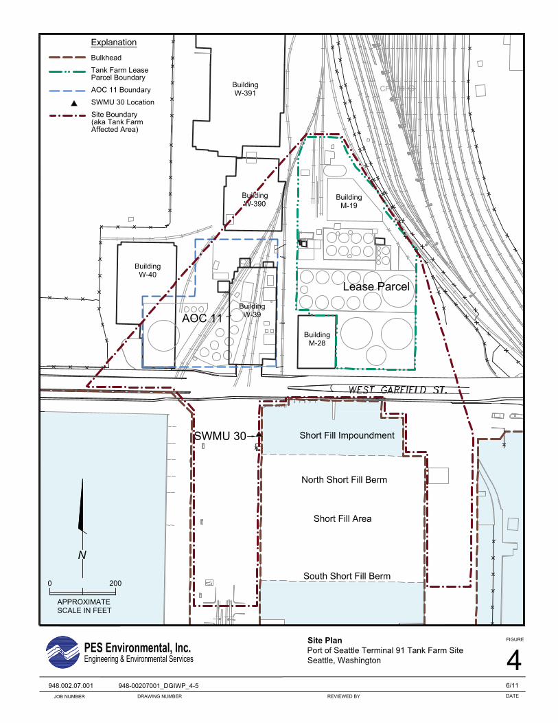
2000
APPROXIMATE
FIGURE
4REVIEWED BYDRAWING NUMBERJOB NUMBER
948.002.07.001
SCALE IN FEET
N
Site PlanPort of Seattle Terminal 91 Tank Farm SiteSeattle, Washington
CP-109
948-00207001_DGIWP_4-5 6/11
Explanation
Bulkhead
Tank Farm LeaseParcel Boundary
AOC 11 Boundary
SWMU 30 Location
Site Boundary(aka Tank FarmAffected Area)

2000
APPROXIMATE
FIGURE
5REVIEWED BYDRAWING NUMBERJOB NUMBER
948.002.07.001
SCALE IN FEET
N
Pipeline CorridorsPort of Seattle Terminal 91 Tank Farm SiteSeattle, Washington
CP-109
948-00207001_DGIWP_4-5 6/11
Explanation
Bulkhead
Tank Farm LeaseParcel Boundary
AOC 11 Boundary
SWMU 30 Location
Site Boundary(aka Tank FarmAffected Area)
ApproximatePipeline Corridors

FIGURE
6DATE
6/11REVIEWED BYJOB NUMBER
948.002.07.001
Alternative 4 - Containment, Enhanced Product RecoveryPort of Seattle Terminal 91 Tank Farm SiteSeattle, Washington
DRAWING NUMBER
948-00207001_DGIWP_6
500
APPROXIMATESCALE IN FEET
N
Explanation
Monitoring Well LocationCP-107
Pilot Test Well LocationCP-PR01
Lease Parcel Boundary
LNAPL Monitoring WellLocationPR-03
Note:1. Tank farm is shown for illustrative
purposes only. Tank farm has been demolished and paved.
Slurry Wall, 2 ft. wide by 20 ft. deep
Trench, 15 ft. wide by 3 ft. deep
Structures to be Removed
Product Recovery Trench

1000
APPROXIMATE
FIGURE
REVIEWED BYDRAWING NUMBERJOB NUMBER
948.002.07.001
SCALE IN FEET
N
SWMU 30 - Limited ExcavationPort of Seattle Terminal 91Seattle, Washington
948-00207001_DGIWP_7 6/11
DecommissionedCP-GP04 Monitoring Well Location
Abandoned PetroleumProduct Line
Approximate 1990 Limitsof LNAPL in Subsurface
Soil Boring LocationB-1
CP-110 Monitoring Well Location
Phase I and II Direct-PushDrilling LocationDG-70
Explanation
Bulkhead
Tank Farm LeaseParcel Boundary
AOC 11 Boundary
Excavation of Soilwith LNAPL
7
1. Tank farm is shown for illustrativepurposes only. Tank farm has been demolished and paved.
Excavation of Soilabove RSSLs
Note:

FIGURE
8DATE
6/11REVIEWED BYJOB NUMBER
948.002.07.001
Proposed Soil Boring and Test Pit LocationsPort of Seattle Terminal 91 Tank Farm SiteSeattle, Washington
DRAWING NUMBER
948-00207001_DGIWP_08
500
APPROXIMATESCALE IN FEET
N
Explanation
Monitoring Well LocationCP-107
Pilot Test Well LocationCP-PR01
Lease Parcel Boundary
LNAPL Monitoring WellLocationPR-03
Note:1. Tank farm is shown for illustrative
purposes only. Tank farm has been demolished and paved.
Slurry Wall, 2 ft. wide by 20 ft. deep
Trench, 15 ft. wide by 3 ft. deep
Proposed Test Pit
Product Recovery Trench
Location
Proposed GeotechnicalBoring Location
B-1
TP-1

APPENDIX A
INVESTIGATION-DERIVED WASTE HANDLING PROCEDURES

PES Environmental, Inc.
S94800701W_1472 Data Gaps Investigation Work Plan – Appendix A
INVESTIGATION-DERIVED WASTE HANDLING PROCEDURES Investigation-derived wastes (IDWs) include solid and liquid wastes in the following field categories:
Soil cuttings;
Decontamination rinsates;
Extracted groundwater;
Miscellaneous disposable materials; and
Used well materials. Subsequent sections describe these IDWs and the specific procedures to be followed for their handling and disposal.
A1.0 ONSITE CONTAINER OPERATIONS
A1.1 Waste Containers
Three types of containers potentially will be used for the temporary storage of IDWs: 55-gallon steel drums with steel lids, 55-gallon poly drums with bung top, and five-gallon plastic buckets with plastic lids. Considering the large volume of wastewater generated during well purging and equipment decontamination, it is generally more practical to use drums than buckets for wastewater storage. If buckets are used, many more containers are required. Also, usually drums can be transported more efficiently and more safely (e.g., with a forklift) than buckets. Drums are appropriate for regulated waste as well as for non-regulated waste. However, if a situation arises in which the use of drums will delay field operations, then field personnel have the option of using buckets instead.
A1.2 Container Labeling
In those cases where IDWs are containerized onsite, the PLP Group’s field-support personnel will carefully label every container as to its contents (see below), and the dates on which the wastes were placed in the container. The date label will include a beginning date, which is the initial date when waste material was placed in the container, and an ending date, which is the last date when waste material was placed in the container.
A1.3 Container Sealing and Staging
When each container is filled, the PLP Group’s field-support personnel will label the container as “full” and notify proper personnel for disposal. The PLP Group personnel will then seal and stage the full container, and replace it with an empty container. This will minimize the potential for releases to the environment and will allow field activities to proceed with minimum delay.

PES Environmental, Inc.
S94800701W_1472 Data Gaps Investigation Work Plan – Appendix A
The PLP Group personnel will seal any partially filled containers and place them in a suitable overnight storage location so that they can be further used on the following workday.
A2.0 WASTE COLLECTION AND STORAGE
A2.1 Soil Cuttings
This category includes the following solid wastes from soil borings:
Soil cuttings;
Non-soil debris that may be removed from the subsurface during drilling;
Concrete and asphalt surface pavement cuttings; and
Soil samples that are collected for logging and field screening, but are not submitted to a laboratory for analysis.
All such wastes will be containerized. Each container will be labeled as to its contents (e.g., “soil cuttings”), and the boring(s) and depth interval(s) from which they were obtained (e.g., “W-10, 0-4.5 ft bgs”).
A2.2 Extracted Groundwater and Decontamination Rinsates
This category consists of groundwater extracted in conjunction with monitoring-well development, purging, sampling, and hydraulic testing, as well as liquid wastes generated by field decontamination of equipment and/or materials (decontamination rinsates).
Extracted groundwater will be containerized. Each container will be labeled as to its contents (e.g., “groundwater”), and the well/piezometer from which it was extracted (e.g., “GP-13”). All containers containing groundwater will be used for groundwater and decontamination rinsates.
The PLP Group personnel will use groundwater-sample analysis results to determine if the waste is to be managed as a non-regulated waste, regulated as a dangerous waste as defined by WAC 173-303, or regulated as a RCRA hazardous waste. The containers will be staged onsite until the analysis results have been reviewed. Rinsates will include a mixture of those liquids prescribed by the SOP for field decontamination (see SOP-200), and residual soil and/or groundwater.
Decontamination rinsates will be containerized with extracted groundwater.
A2.3 Miscellaneous Disposable Materials
This category includes the following solid wastes:
Disposable materials used for the decontamination of field equipment (e.g., plastic sheeting and bags, tape, cloth or paper towels, etc.);

PES Environmental, Inc.
S94800701W_1472 Data Gaps Investigation Work Plan – Appendix A
Used, disposable, personal protective equipment (e.g., disposable gloves and protective suits, respirator filter cartridges, etc.); and
Disposable materials used for soil/groundwater-sampling, hydraulic testing, well
sounding, and water-level measurement (e.g., rope, flexible tubing, bailers).
A3.0 DISPOSAL OF WASTES
A3.1 Non-Regulated Wastes
Non-regulated solid wastes will be disposed of in one of the following ways:
Disposal by a local municipal waste disposal service.
Transported to a sanitary landfill or other non-regulated waste handling facility. Non-regulated liquid wastes will be transported to an appropriate facility for disposal. A3.2 Dangerous and Hazardous Wastes
The discussion in this section applies to both liquid and solids generated during investigative activities. Dangerous wastes will be disposed of according to all applicable state and federal hazardous and dangerous waste regulations.

PES Environmental, Inc.
APPENDIX B
STANDARD OPERATING PROCEDURES

Standard Penetration Tests and Split Spoon Sampling SOP-103 Date Initiated: 7/1/98 Revision Date: 7/6/01 Revision No. 1 Page 1 Standard Penetration Tests and Split Spoon Sampling This SOP contains eight sections: 1.0 Purpose 2.0 Application 3.0 References 4.0 Associated SOPs 5.0 Equipment 6.0 Decontamination 7.0 Standard Penetration Test Procedures 8.0 Split Spoon Sampling Procedures 1.0 Purpose The purpose of this SOP is to provide geotechnical field personnel with an outline of the specific information needed to conduct and document standard penetration tests and split spoon sampling. The required equipment and field forms are also outlined for each of these procedures. 2.0 Application This SOP provides a step-by-step guideline to be followed by the site geologist when obtaining split spoon samples during drilling operations. 3.0 References None 4.0 Associated SOPs PSC-101 – Collection and Handling of Sediment Samples PSC-102 – Collection and Handling of Surface Soil Samples PSC-106 – Soil Gas Monitoring Location Installation PSC-200 – Equipment Decontamination Procedure PSC-300 – Photo-ionization Detector Calibration and Operation PSC-400 – Documentation Procedures 5.0 Equipment The following equipment is required to properly conduct split spoon sampling and standard penetration tests from soil borings:

Standard Penetration Tests and Split Spoon Sampling SOP-103 Date Initiated: 7/1/98 Revision Date: 7/6/01 Revision No. 1 Page 2
• a 24 inch or 60 inch split spoon sampler, including sample traps;
• sample characterization equipment such as a Geological Society of America Rock-Color Chart (Munsell System), a 10x (minimum) hand lens, a rigid two foot ruler (accurate to a hundredth of a foot), the Unified Soil Classification System, and an organic vapor analyzer (e.g. a photoionization detector, HNU PI-101, or a flume ionization detector, OVA)
• a stainless steel bowl and scoop;
• sample bottles, including labels, and;
• all personal protective and decontamination equipment required in the project sampling plan and Standard Operating Procedure PSC-200 and PSC-202
6.0 Decontamination All equipment which will come in contact with the subsurface and/or be used to acquire a sample will be decontaminated prior to arrival on site, between samples, and site exit. Standard Operating Procedure PSC-200 shall be followed. 7.0 Standard Penetration Test Engineering and physical properties of soil may be of interest should site construction activities be planned. Soil types, bearing strength, compressibility, permeability, plasticity, and moisture content are some of the physical characteristics that may be determined on soil samples. The ASTM Standard Penetration Test (SPT) is an important component in identifying some of these characteristics (e.g., relative density, compactness, and cohesiveness). The following procedure must be followed in order to conduct the SPT:
• Attach a decontaminated 24 inch split spoon sampler to the appropriate length of drill rods and gently lower the sampler to the bottom of the bore hole (the spoon should only be handled while wearing a clean pair of Latex gloves in order to reduce the risk of contamination). The spoon should be resting on undisturbed soil at the upper boundary of the soil interval to be sampled;
• mark 6 inch increments on the drill rod upward from a rigid surface datum (e.g., ground surface or hollow stem auger drill casing), for a length of 24 inches;
• drive the split spoon into the soil using a certified 140 lb. Hammer dropped consistently from a height of 30 inches;
• count and record the number of blows struck by the hammer for each six inch increment of penetration;

Standard Penetration Tests and Split Spoon Sampling SOP-103 Date Initiated: 7/1/98 Revision Date: 7/6/01 Revision No. 1 Page 3
• the test is completed when either the spoon has been driven 24 inches or when 100 blows are counted within a 6 inch increment before the complete 6 inch penetration of the increment has been obtained (refusal); and,
• if refusal occurs at anytime during the test, record the number of blows counted for each 6 inch increment penetrated prior to refusal, and then 100 blows per the amount of penetration (to the nearest hundredth of a foot) attained during the final increment.
In situations where the weight of the drill rods (w/r) or the weight of the hammer and drill rods together (w/h) is sufficient to drive the split spoon into soil without inflicting blows from the hammer, this should be recorded on the Soil Boring Logs as “w/r” or “w/h” for each applicable 6 inch increment. 8.0 Split Spoon Sampling Procedure Subsurface soil samples are collected in order to accurately characterize local stratigraphic compositions and interfaces. The following procedures for retrieving and logging a subsurface soil sample via split spoon sampling shall be followed:
• 24 inch split spoon soil samples will be collected at ground surface and at 5.0 foot intervals, unless otherwise indicated in the Sampling Plan;
• the SPT will be conducted for each sample and the blows recorded on the geologic sample label and on the Soil Boring Logs;
• upon completion of the SPT, the split spoon is brought to the surface and removed from the drill rods;
• the split spoon sample will be opened and immediately screened for organic vapors by the site geologist using a calibrated photo or flame ionization detector (PSC-300). Organic vapor measurements are made by placing the instrument probe approximately 1.5 inches from the sample core and slowly passing the probe over the length of the sample;
• record the highest reading obtained, and the position of that reading along the length (depth) of the spoon in both the field notebook and on the Soil Boring Logs;

T91 Tank Farm Site SOP Equipment Decontamination Procedure SOP - 200 Origination Date: 1/28/03 Revision Date: 1/28/03 Revision No.0 Page 1 of 4 This standard operating procedure (SOP) contains eight sections: 1.0 Purpose 2.0 Application 3.0 References 4.0 Associated SOPs 5.0 Equipment 6.0 General Decontamination Procedures
6.1 Decontamination When Organic Constituents Are of Interest 6.2 Decontamination When Inorganic Constituents Are of Interest 6.3 Decontamination When Inorganic and Organic Constituents Are of
Interest 7.0 Specific Decontamination Procedures
7.1 Non-Dedicated Submersible Pump Decontamination Procedure 8.0 Documentation 9.0 Measure of Proficiency
1.0 Purpose The purpose of this SOP is to provide field personnel with an outline of the procedure and frequency of decontaminating equipment that has come into contact with monitoring well water.
2.0 Application This SOP provides a step-by-step guideline to be followed by the field sampling crew to prevent cross-contamination between monitoring wells and preserve well integrity.
3.0 References RCRA Groundwater Draft Technical Guidance (EPA, 1992)

T91 Tank Farm Site SOP Equipment Decontamination Procedure SOP - 200 Origination Date: 1/28/03 Revision Date: 1/28/03 Revision No.0 Page 2 of 4 4.0 Associated SOPs Measuring Water, LNAPL, and DNAPL Elevations
Monitoring Well Development Low Flow Groundwater Sampling Procedure Documentation Procedures
5.0 Equipment The following equipment is necessary to properly decontaminate equipment used with monitoring wells: • De-ionized water and spray bottle. • Alconox and spray bottle, hexane and spray bottle, and 10% Nitric acid and spray
bottle, paper towels/rags. • PVC pipe, capped on one end, 5 feet long. • A clean hose and tap water source. • A labeled 55-gallon drum for wastewater and a bucket to use for smaller volume prior
to containing in drum. • Personal protective equipment as described in the Site Health and Safety Plan.
6.0 General Decontamination Procedures All reusable equipment that will come in contact with the well and/or be used to acquire samples will be decontaminated prior to arrival on site, relocation on site, and site exit.
6.1 Decontamination When Organic Constituents Are of Interest • Wash the equipment with a solution of nonphosphate detergent (Alconox or
equivalent) and water. • Rinse the equipment with tap water. • Rinse the equipment with Hexane.

T91 Tank Farm Site SOP Equipment Decontamination Procedure SOP - 200 Origination Date: 1/28/03 Revision Date: 1/28/03 Revision No.0 Page 3 of 4 • Rinse the equipment with DI water.
6.2 Decontamination When Inorganic Constituents Are of Interest • Wash the equipment with a solution of nonphosphate detergent (Alconox or
equivalent) and water. • Rinse the equipment with tap water. • Rinse the equipment with 10% Nitric Acid solution. • Rinse the equipment with DI water.
6.3 Decontamination When Inorganic and Organic Constituents Are of Interest
• Wash the equipment with a solution of nonphosphate detergent (Alconox or equivalent) and water.
• Rinse the equipment with tap water. • Rinse the equipment with Hexane. • Rinse the equipment with DI water. • Rinse the equipment with 10% Nitric Acid solution. • Rinse the equipment with DI water.
7.0 Specific Decontamination Procedures
7.1 Non-Dedicated Submersible Pump Decontamination Procedure After sampling or developing a well using a non-dedicated submersible pump, decontaminate the pump as follows: • Use hose to spray off pump with tap water. • Place pump into a capped approximately 5’ long, 3” diameter PVC pipe. • Fill the PVC pipe with tap water and detergent. • Run the pump until the pipe is empty, refilling it with tap water 3 times. The
discharge decontamination water will be pumped into a 55-gallon drum. • Remove the pump and wash out the pipe using tap water from the hose. • Place the pump in the pipe again and fill with tap water. • Repeat the process, running the pump until the pipe empties 3 times, when there is
half a pipe of water left, add 2L of Hexane and continue pumping until pipe is empty.

T91 Tank Farm Site SOP Equipment Decontamination Procedure SOP - 200 Origination Date: 1/28/03 Revision Date: 1/28/03 Revision No.0 Page 4 of 4 • Remove the pump and rinse out the pipe with tap water. • Place the pump back in the pipe and fill with tap water. • Run the pump until the pipe empties 3 times, when there is half a pipe of water left
add 2L of 10% Nitric Acid. • Run the pump until it empties, then rinse it with water and refill the pipe with di-
ionized water. • Run the pump until the pipe empties three times with the deionized water.
8.0 Documentation Documentation of all decontamination procedures associated with monitoring well activities including all field forms and the maintenance of a detailed field book as described in SOP-400.
9.0 Measure of Proficiency Field staff will demonstrate proficiency on this SOP by successfully completing sections 6.0, 7.0, and 8.0 a minimum of twice under the direct supervision of the Port of Seattle (POS) Well Sampling Manager or her/his designee.

T91 Tank Farm Site SOP Documentation Procedures SOP - 400 Origination Date: 1/28/03 Revision Date: 1/28/03 Revision No.0 Page 1 of 3
This standard operating procedure (SOP) contains seven sections: 1.0 Purpose 2.0 Application 3.0 References 4.0 Associated SOPs 5.0 Field Books 6.0 Field Forms 7.0 Measure of Proficiency
1.0 Purpose The purpose of this SOP is to outline, in detail, the required documentation needed to maintain accurate logs and files of all field procedures.
2.0 Application This SOP provides documentation guidelines, including examples, required for all geotechnical exploratory and sampling procedures.
3.0 References None
4.0 Associated SOPs Measuring Water, LNAPL, and DNAPL Elevations Monitoring Well Development Low Flow Groundwater Sampling Procedure Equipment Decontamination Procedure
5.0 Field Books All field books should be pocket size “Rite in the Rain” or equivalent and should have non-removable pages. These field books are to be dedicated to a project, and the field sampling crew is responsible for maintaining a field book inventory. This inventory

T91 Tank Farm Site SOP Documentation Procedures SOP - 400 Origination Date: 1/28/03 Revision Date: 1/28/03 Revision No.0 Page 2 of 3
should include a numbering and tracking mechanism for each field book assigned to a particular case. Alternatively, information will be documented using the Port of Seattle's (POS) Environmental Management Information System's (EMIS) Field Summary Data Sheet (FSDS) module. This system is a laptop-based environment designed to accept direct input of field data. The system allows for printout of location specific information or site summary information. Following a field event, the information is quickly and accurately uploaded to the POS's EMIS database for review and dissemination. Each field book or FSDS is to be maintained as follows:
• Label the outside front cover with the following information: PLP Group, Pier 91, Dates Included, and Book Number. The inside cover should include: Pier 91, Project Manager’s name, Site address, Project Manager's phone number, dates included, and book number.
• Inside the cover, list the full names and initials of each person working on the
project that will be referred to in the field book.
• Maintain all field notes directly in the field books (i.e. notes are not to be taken then transferred to the field books at a later time).
• Record all field notes in permanent ink (sharpie markers).
• Initial, date, and number each page upon completion.
• Correction of mistakes are made with a single line and initialing and dating the
correction.
• Avoid blank spaces within the notes. Unavoidable blank spaces are to be struck with a single line.
Examples of information required in the field book include:
• The date of entry. • Time of entry for specific events (in military time). • A meteorological description of daily changes. • Personnel present including arrival and departure times and affiliations. • Make, model and condition of equipment used.
T91 Tank Farm Site SOP Documentation Procedures SOP - 400 Origination Date: 1/28/03 Revision Date: 1/28/03 Revision No.0 Page 3 of 3
• The time interval and reasons for delays including a detailed description of corrective actions taken by the field crew.
• A detailed description and rationale for any deviations from the Work Plan, Sampling Plan, or Health and Safety Plan.
6.0 Field Forms The field forms, hard copy or electronic, have been designed to detail all steps, actions, and readings associated with specific field procedures. These forms are to be completed in full. No sections are to be left blank, if a section is “not applicable”, it is to be indicated as such. All forms, including location diagrams, are to be completed in the field with permanent ink.
7.0 Measure of Proficiency Proficiency assessment for documentation is associated with specific procedural proficiency, therefore, no separate proficiency measures for documentation are needed.

PES Environmental, Inc.
S94800701W_1472
DISTRIBUTION FINAL
DATA GAPS INVESTIGATION WORK PLAN TERMINAL 91 TANK FARM AFFECTED AREA CLEANUP
OCTOBER, 2011
COPY NO. _____
Copy No.
1 Copy Washington Department of Ecology 1 Northwest Regional Office
3190 160th Avenue SE Bellevue, Washington 98008-5452 Attn: Sharon Aboe, HWTR
1 Copy Washington Department of Ecology 2 Bellingham Field Office 1440 10th Street, Suite 102 Bellingham, Washington 98225-7028
Attention: Mr. Galen Tritt 1 Copy Washington State Department of Ecology 3
15 West Yakima Avenue, Suite 200 Yakima, Washington 98902-3452 Attention: Mr. Greg Caron
1 Copy Port of Seattle 4 1 e-Copy P.O. Box 1209
Pier 69 Seattle, Washington 98111 Attention: Mr. Fred Chou, Ms. Kathy Bahnick
1 e-Copy Roth Consulting N/A
6236 27th Avenue NE Seattle, Washington 98115-7114
Attention: Ms. Susan Roth 1 Copy PES File Copy 5


