Filtro de succión HYDAC
8
241 E 7.406.1/03.12 1. TECHNICAL SPECIFICATIONS 1.1 FILTER HOUSING Construction The filter housings are designed in accordance with international regulations. The SF filters consist of a filter housing and a bolt-on cover plate. The SFM and SFF filters consist of a filter head with filter bowl and bolt-on cover plate (on the SFF there is a foot valve in the base of the filter bowl). Standard equipment: bypass valve connection for a clogging indicator 1.2 FILTER ELEMENTS HYDAC filter elements are validated and their quality is constantly monitored according to the following standards: ISO 2941 ISO 2942 ISO 2943 ISO 3724 ISO 3968 ISO 11170 ISO 16889 The suction elements S are designed to be screwed into the suction line on pumps or inside tanks. The suction filter elements S.. are designed to be mounted simply onto the outside of the tank. Hoses and fittings must be supported to avoid any load on the connection. Elements can be changed very simply. It is essential that suction filter elements are always installed well below the minimum oil level. Standard equipment: without bypass valve Filter elements are available with the following pressure stability values: Paper (P): 5 bar Wire mesh (W): 5 bar 1.4 SEALS NBR (= Perbunan) 1.5 INSTALLATION As tank-top or inline filter. 1.6 SPECIAL MODELS AND ACCESSORIES On request 1.7 SPARE PARTS See Original Spare Parts List 1.8 CERTIFICATES AND APPROVALS On request 1.9 COMPATIBILITY WITH HYDRAULIC FLUIDS ISO 2943 Hydraulic oils H to HLPD DIN 51524 Lubrication oils DIN 51517, API, ACEA, DIN 51515, ISO 6743 Compressor oils DIN 51506 Biodegradable operating fluids VDMA 24568 HETG, HEES, HEPG Fire-resistant fluids HFA, HFB, HFC and HFD Operating fluids with high water content (>50% water content) on request 1.10 IMPORTANT INFORMATION Filter housings must be earthed. When using electrical clogging indicators, the electrical power supply to the system must be switched off before removing the clogging indicator connector. 1.3 FILTER SPECIFICATIONS Nominal pressure Suction operation Temperature range -10 °C to +100 °C Material of SF filter Cover plate: aluminium Housing: aluminium Material of SFM filter Cover plate: aluminium Filter head: aluminium Filter bowl: polyamide Material of SFF filter Cover plate: GGG40 Filter head: aluminium Filter bowl: steel Material of S elements Filter mesh: wire mesh End caps: polyamide Central tube: steel, zinc-plated Material of S.. elements Filter mesh: wire mesh End caps: on request Central tube: on request Type of clogging indicator VR Connection thread G ½ V1/4 Conn. thread NPT (only SFF) Pressure setting of the clogging indicator 0.2 to 2 bar (others on request) Bypass cracking pressure 0.25 bar (SFF filter) 0.3 bar (SF and SFM filter) (others on request) Cracking pressure of bypass valve for 0.2 bar suction filter elements S (optional) Symbol for hydraulic systems E 7.406.1/03.12 Suction Filter SF/SFM/SFF and Suction Filter Elements S/S.. up to 500 l/min SF 60 SF 110 Filters: Elements: SF 160 SF 240 SF 330 SFM 330 SFF 400 SFF 500 S SH. SU. SG. SF, SFM, SFF S elements VA = clogging indicator
-
Upload
ayrton-mendoza -
Category
Documents
-
view
40 -
download
6
Transcript of Filtro de succión HYDAC

241
E 7.
406.
1/03
.12
1. TECHNiCAL SPECiFiCATiONS
1.1 FiLTER HOUSiNGConstruction The filter housings are designed in accordance with international regulations. The SF filters consist of a filter housing and a bolt-on cover plate. The SFM and SFF filters consist of a filter head with filter bowl and bolt-on cover plate (on the SFF there is a foot valve in the base of the filter bowl).Standard equipment:
bypass valveconnection for a clogging indicator1.2 FiLTER ELEMENTS
HYDAC filter elements are validated and their quality is constantly monitored according to the following standards:
ISO 2941ISO 2942 ISO 2943 ISO 3724ISO 3968 ISO 11170ISO 16889
The suction elements S are designed to be screwed into the suction line on pumps or inside tanks. The suction filter elements S.. are designed to be mounted simply onto the outside of the tank. Hoses and fittings must be supported to avoid any load on the connection. Elements can be changed very simply. It is essential that suction filter elements are always installed well below the minimum oil level.Standard equipment:
without bypass valve
Filter elements are available with the following pressure stability values:Paper (P): 5 bar Wire mesh (W): 5 bar
1.4 SEALSNBR (= Perbunan)
1.5 iNSTALLATiONAs tank-top or inline filter.
1.6 SPECiAL MODELS AND ACCESSORiESOn request
1.7 SPARE PARTSSee Original Spare Parts List
1.8 CERTiFiCATES AND APPROVALSOn request
1.9 COMPATiBiLiTY WiTH HYDRAULiC FLUiDS iSO 2943
Hydraulic oils H to HLPD DIN 51524Lubrication oils DIN 51517, API,
ACEA, DIN 51515, ISO 6743Compressor oils DIN 51506Biodegradable operating fluids VDMA
24568 HETG, HEES, HEPGFire-resistant fluids HFA, HFB, HFC
and HFDOperating fluids with high water
content (>50% water content) on request
1.10 iMPORTANT iNFORMATiONFilter housings must be earthed.When using electrical clogging
indicators, the electrical power supply to the system must be switched off before removing the clogging indicator connector.
1.3 FiLTER SPECiFiCATiONS Nominal pressure Suction operation Temperature range -10 °C to +100 °C Material of SF filter Cover plate: aluminium Housing: aluminium Material of SFM filter Cover plate: aluminium Filter head: aluminium Filter bowl: polyamide Material of SFF filter Cover plate: GGG40 Filter head: aluminium Filter bowl: steel Material of S elements Filter mesh: wire mesh End caps: polyamide Central tube: steel, zinc-plated Material of S.. elements Filter mesh: wire mesh End caps: on request Central tube: on request Type of clogging indicator VR Connection thread G ½ V1/4 Conn. thread NPT (only SFF) Pressure setting of the clogging indicator 0.2 to 2 bar (others on request) Bypass cracking pressure 0.25 bar (SFF filter) 0.3 bar (SF and SFM filter) (others on request) Cracking pressure of bypass valve for 0.2 bar suction filter elements S (optional)
Symbol for hydraulic systems
E 7.
406.
1/03
.12
Suction Filter SF/SFM/SFF and Suction Filter Elements S/S..up to 500 l/minSF 60
SF 110
Filters:
Elements:
SF 160
SF 240
SF 330
SFM 330
SFF 400
SFF 500
S
SH.
SU.
SG.
SF, SFM, SFF
S elements
VA = clogging indicator

242
E 7.
406.
1/03
.12
SF W 330 W L 10 UE 1 . X /-V
Filter type SF, SFM, SFFFilter material P paper (not for SFF) W stainless steel wire meshSize of filter or element SF: 60, 110, 160, 240, 330 SFM: 330 SFF: 400, 500Operating pressure W suction operationType and size of connection
Type Connection Filter sizeSF 60
SF 110
SF 160
SF 240
SF 330
SFM 330
SFF 400
SFF 500
C G ¾ E G 1¼ F G 1½ G G 2 K SAE DN 40 (1½") L SAE DN 50 (2") M SAE DN 65 (2½") P SAE DN 100 (4")
Filtration rating P: 10, 20 (not for SFF) W: 75, 125Type of clogging indicator A steel blanking plug in indicator port E pressure gauge for other clogging indicators UE vacuum gauge see brochure no. 7.050../.. UF vacuum switchType code 1 Modification number X the latest version is always suppliedSupplementary details KB without bypass valve V FPM seals W suitable for HFA and HFC emulsions
2. MODEL CODE (also order example)2.1 COMPLETE FiLTER
0330 RS 075 W /-VSize 0060, 0110, 0160, 0240, 0330, 0400, 0500Type RSFiltration rating in µm P: 010, 020 (not for SFF) W: 075, 125Filter material P, WSupplementary details SFF must be added to model code for SFF filter V, W (for descriptions, see Point 2.1)
2.2 REPLACEMENT ELEMENT FOR SF / SFM / SFF FiLTERS
2.3 REPLACEMENT CLOGGiNG iNDiCATOR VR 1 UE . X /-VType VR connection thread G ½ (only for SF and SFM filter) V1/4 connection thread NPT (only for SFF filter)Pressure setting 2 2 bar (for type E) 1 1 bar (for type UE) 0.2 0.2 bar (for type UF)Type of clogging indicator (see Point 2.1)Modification number X the latest version is always suppliedSupplementary details V (for descriptions, see point 2.1)
243
E 7.
406.
1/03
.12
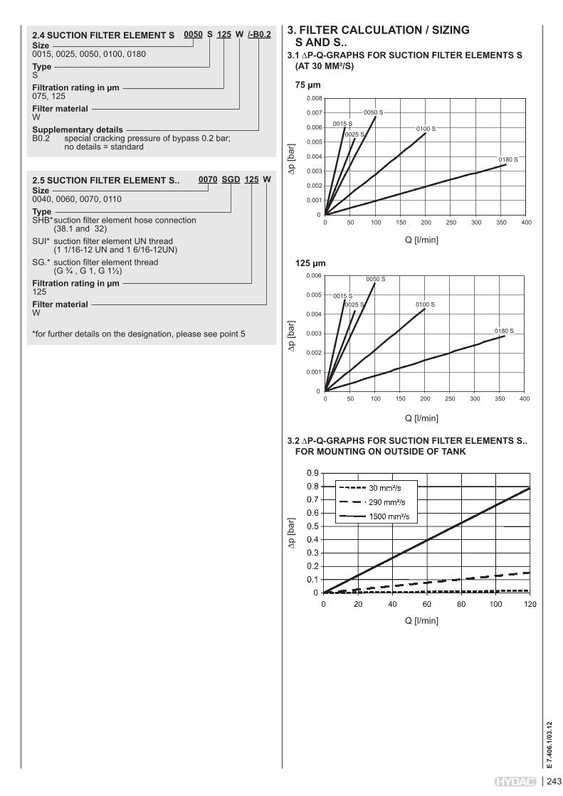
0050 S 125 W /-B0.2Size 0015, 0025, 0050, 0100, 0180Type SFiltration rating in µm 075, 125Filter material WSupplementary details B0.2 special cracking pressure of bypass 0.2 bar; no details = standard
2.4 SUCTiON FiLTER ELEMENT S
0070 SGD 125 WSize 0040, 0060, 0070, 0110Type SHB* suction filter element hose connection (38.1 and 32)SUI* suction filter element UN thread (1 1/16-12 UN and 1 6/16-12UN)SG.* suction filter element thread (G ¾ , G 1, G 1½) Filtration rating in µm 125Filter material W *for further details on the designation, please see point 5
2.5 SUCTiON FiLTER ELEMENT S..
3. FiLTER CALCULATiON / SiZiNG S AND S..
3.1 ∆P-Q-GRAPHS FOR SUCTiON FiLTER ELEMENTS S (AT 30 MM²/S)
75 µm
∆p [b
ar]
Q [l/min]
0
0.001
0.002
0.003
0.004
0.005
0.006
0.007
0.008
0 50 100 150 200 250 300 350 400
0050 S
0015 S
0025 S0100 S
0180 S
125 µm
∆p [b
ar]
Q [l/min]
0
0.001
0.002
0.003
0.004
0.005
0.006
0 50 100 150 200 250 300 350 400
0050 S
0015 S0025 S 0100 S
0180 S
3.2 ∆P-Q-GRAPHS FOR SUCTiON FiLTER ELEMENTS S.. FOR MOUNTiNG ON OUTSiDE OF TANk
∆p [b
ar]
Q [l/min]

244
E 7.
406.
1/03
.12
4. FiLTER CALCULATiON / SiZiNG SF, SFM, SFFThe total pressure drop of a filter at a certain flow rate Q is the sum of the housing ∆p and the element ∆p and is calculated as follows:∆ptotal =∆phousing+∆pelement
∆phousing = (see Point 4.1)
∆pelement = Q • SK* • viscosity 1000 30 (*see point 4.2)For ease of calculation, our Filter Sizing Program is available on request free of charge.NEW: Sizing online at www.hydac.com
4.1 ∆p-Q HOUSiNG CURVES BASED ON iSO 3968The housing curves apply to mineral oil with a density of 0.86 kg/dm³ and a kinematic viscosity of 30 mm²/s. In this case, the differential pressure changes proportionally to the density.
SF 60, 100
∆p [b
ar]
Q [l/min]
SF 160, 240
∆p [b
ar]
Q [l/min]
SF 330
∆p [b
ar]
Q [l/min]
∆p [b
ar]
Q [l/min]
SFF 400, 500
SFM 330
∆p [b
ar]
Q [l/min]
4.2 GRADiENT COEFFiCiENTS (Sk) FOR FiLTER ELEMENTS (FOR SF/SFM/SFF FiLTERS)The gradient coefficients in mbar/(l/min) apply to mineral oils with a kinematic viscosity of 30 mm²/s. The pressure drop changes proportionally to the change in viscosity.
RS W 75 µm 125 µm60 1.03 0.54110 0.52 0.26160 0.36 0.19240 0.25 0.13330 0.19 0.10400 0.20 0.16500 0.20 0.16
0
0.02
0.04
0.06
0.08
0.1
0.12
0.14
0 100 200 300 400 500 600 700
SFF 400 SFF 500
60 W
∆p [b
ar]
Q [l/min]
110 W
∆p [b
ar]
Q [l/min]
∆p [b
ar]
Q [l/min]
240 W
160 W
∆p [b
ar]
Q [l/min]
∆p [b
ar]
Q [l/min]
400 W
330 W
∆p [b
ar]
Q [l/min]∆p
[bar
]
Q [l/min]
500 W

245
E 7.
406.
1/03
.12
5. DiMENSiONSSuction filter element S
bypass valve (optional)
Types A B C D E SW Flow rate (ISO 228) l/min0015 S 44 104 G ½ 24 10.5 30 150025 S 63 127 G ¾ 36 13.5 46 250050 S 63 159 G 1 36 13.5 46 500100 S 86 210 G 1½ 46 18.5 69 1000180 S 86.5 311 G 2 46 18.5 69 180
Designation G E d L1 L2 SW0110 SHB 125 W 38.1 2½-12 UN 2 B 32 176 158 700070 SHB 125 W 32.0 1 7/8-12 UNF 25 176 158 550060 SHB 125 W 32.0 1 7/8-12 UNF 25 143 125 550070 SUI 125 W 1 1/16-12 UN 1 7/8-12 UNF - 176 158 550060 SUI 125 W 1 1/16-12 UN 1 7/8-12 UNF - 143 125 550110 SGF 125 W G 1½ 2½-12 UN 2 B 34 176 158 700070 SGD 125 W G 1 2½-12 UN 2 B 25 176 158 600040 SGC 125 W G ¾ 1 7/8-12 UNF 20 143 125 55
Type SHB
Suction filter element S.. for mounting on the outside of tank
Type SUI
Type SGx
246
E 7.
406.
1/03
.12
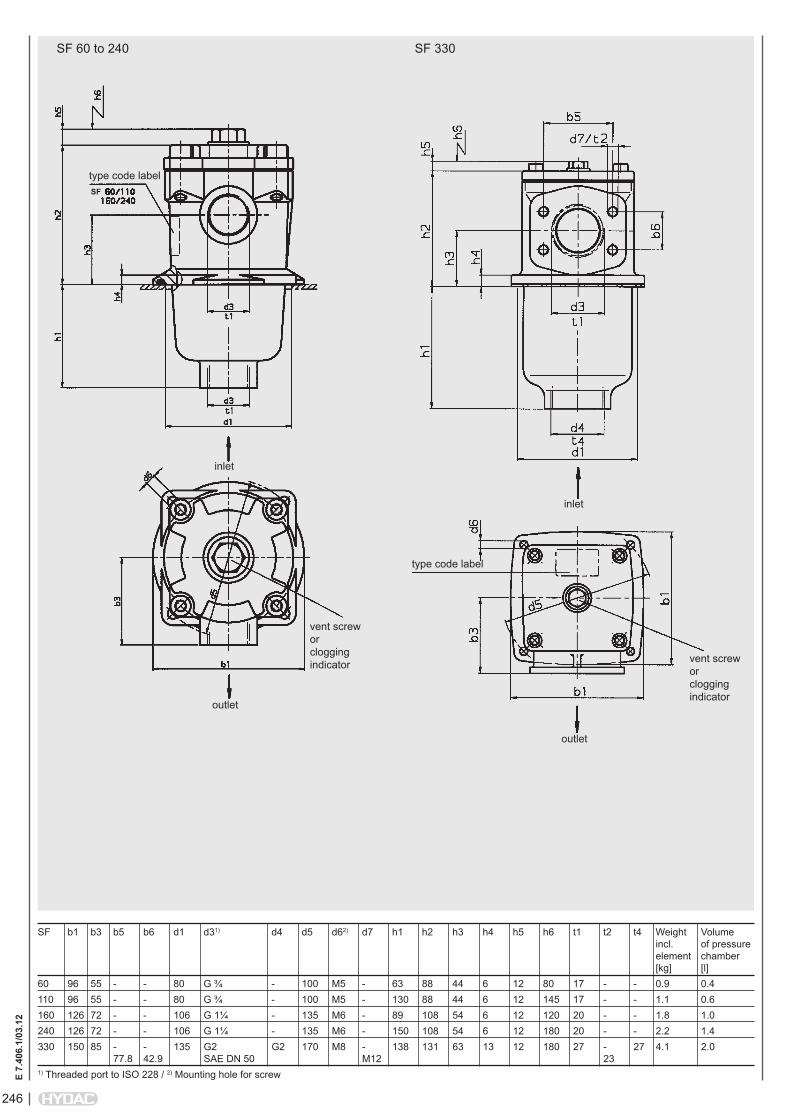
SF 60 to 240
type code label
outlet
inlet
vent screw or clogging indicator
SF b1 b3 b5 b6 d1 d31) d4 d5 d62) d7 h1 h2 h3 h4 h5 h6 t1 t2 t4 Weight Volume incl. of pressure element chamber [kg] [l]60 96 55 - - 80 G ¾ - 100 M5 - 63 88 44 6 12 80 17 - - 0.9 0.4110 96 55 - - 80 G ¾ - 100 M5 - 130 88 44 6 12 145 17 - - 1.1 0.6160 126 72 - - 106 G 1¼ - 135 M6 - 89 108 54 6 12 120 20 - - 1.8 1.0240 126 72 - - 106 G 1¼ - 135 M6 - 150 108 54 6 12 180 20 - - 2.2 1.4330 150 85 - - 135 G2 G2 170 M8 - 138 131 63 13 12 180 27 - 27 4.1 2.0 77.8 42.9 SAE DN 50 M12 231) Threaded port to ISO 228 / 2) Mounting hole for screw
SF 330
vent screw or clogging indicator
type code label
outlet
inlet
SF

247
E 7.
406.
1/03
.12
SFM 330
port forclogging indicator
outlet
SFM
330
:S
FM 3
30:
filling connection
inlet
View from below
SFM Weight Volume of incl. pressure element chamber [kg] [l]330 3.9 2.0

248
E 7.
406.
1/03
.12
NOTEThe information in this brochure relates to the operating conditions and applications described. For applications or operating conditions not described, please contact the relevant technical department. Subject to technical modifications.
HYDAC FiLTERTECHNik GMBH Industriegebiet D-66280 Sulzbach/Saar, Germany Tel.: 0 68 97 / 509-01 Fax: 0 68 97 / 509-300 Internet: www.hydac.com E-mail: [email protected]
SFF 400
outlet
SFF 500
crim
p sh
own
out o
f po
sitio
n in
cro
ss-
sect
ion
inle
t
type code label
outlet
crim
p sh
own
out o
f po
sitio
n in
cro
ss-
sect
ion
inle
t
type code label
SFF Volume of pressure chamber [l]400 4.23500 4.63