Filter Clogging Indicators...63 E 7.050.13/03.12 Filter Clogging Indicators 1. TECHNICAL...
46
63 E 7.050.13/03.12 Filter Clogging Indicators 1. TECHNICAL SPECIFICATIONS 1.1 GENERAL HYDAC clogging indicators are designed to indicate visually and/or electrically when the filter elements must be cleaned or changed. The operational safety of a system and efficient utilisation of a filter element can only be guaranteed if clogging indicators are used. Depending on the type of filter, vacuum, return line or differential pressure clogging indicators are used. 1.2 SEALS NBR (= Perbunan) or V (= Viton) 1.3 INSTALLATION Some users install filters without clogging indicators and prefer instead to replace or clean the elements according to a specified time schedule or according to a set number of operating hours. However, this involves some risk. Fitting a clogging indicator has two main advantages: The operator no longer has to estimate when the element is clogged. The unnecessary costs of changing the element too early are avoided. All standard filters can be fitted with a clogging indicator at any time, by simply screwing it in. 1.4 DESIGN Return line indicators These are used for return line and suction filters. In return line filters they react to the increasing static pressure before the filter element, and in suction filters to the decreasing pressure after the filter element, which is caused by increasing contamination. Differential pressure indicators These are used for all inline filters and react to the increasing pressure differential caused by increasing contamination of the filter element. The most simple installation of the differential clogging indicator: G ½" cavity (according to HYDAC works standard HN 28-22) The differential pressure indicator type V02 is piped up separately. E 7.050.13/03.12 1.4 SPECIAL INDICATORS Mobile indicators These indicators have been developed for special applications and are fitted with AMP, Deutsch and Junior Power Timer plugs. ATEX indicators These indicators are used in potentially explosive locations and are subject to the ATEX Equipment Directive 94/9/EC and the ATEX Operator Directive 1999/92/EC. UL and CSA indicators Indicators which are exported to the USA and Canada often require classification according to current UL and CSA standards. The UL and CSA symbols are found on many products, particularly in the field of electrical engineering. clean side Contaminated side 1.6 TABLE OF CONTENTS Contents Page: Quick selection table: by indicator type 64 Quick selection table: by filter type 65 Standard indicators Vacuum Return line Differential pressure 66 69 83 Indicator VL for Condition Monitoring 86 Mobile indicators Return line Differential pressure 91 93 ATEX indicators Return line Differential pressure 96 98 UL/CSA indicators Differential pressure Return line 100 101 Model code - Standard 102 Adapters 104 DESINA Specification 106 www.comoso.com
Transcript of Filter Clogging Indicators...63 E 7.050.13/03.12 Filter Clogging Indicators 1. TECHNICAL...

63
E 7.
050.
13/0
3.12
FilterClogging Indicators
1. TECHNICALSPECIFICATIONS
1.1 GENERALHYDAC clogging indicators are designed to indicate visually and/or electrically when the fi lter elements must be cleaned or changed. The operational safety of a system and effi cient utilisation of a fi lter element can only be guaranteed if clogging indicators are used.Depending on the type of fi lter, vacuum, return line or differential pressure clogging indicators are used.
1.2 SEALSNBR (= Perbunan) or V (= Viton)
1.3 INSTALLATIONSome users install fi lters without clogging indicators and prefer instead to replace or clean the elements according to a specifi ed time schedule or according to a set number of operating hours. However, this involves some risk.Fitting a clogging indicator has two main advantages:
The operator no longer has to estimate when the element is clogged.
The unnecessary costs of changing the element too early are avoided.All standard fi lters can be fi tted with a clogging indicator at any time, by simply screwing it in.
1.4 DESIGNReturn line indicatorsThese are used for return line and suction fi lters. In return line fi lters they react to the increasing static pressure before the fi lter element, and in suction fi lters to the decreasing pressure after the fi lter element, which is caused by increasing contamination.
Differential pressure indicatorsThese are used for all inline fi lters and react to the increasing pressure differential caused by increasing contamination of the fi lter element.The most simple installation of the differential clogging indicator: G ½" cavity (according to HYDAC works standard HN 28-22)The differential pressure indicator type V02 is piped up separately.
E 7.
050.
13/0
3.12
1.4 SPECIAL INDICATORSMobile indicatorsThese indicators have been developed for special applications and are fi tted with AMP, Deutsch and Junior Power Timer plugs.ATEX indicatorsThese indicators are used in potentially explosive locations and are subject to the ATEX Equipment Directive 94/9/EC and the ATEX Operator Directive 1999/92/EC.
UL and CSA indicatorsIndicators which are exported to the USA and Canada often require classifi cation according to current UL and CSA standards. The UL and CSA symbols are found on many products, particularly in the fi eld of electrical engineering.
clean side
Contaminated side
1.6 TABLE OF CONTENTSContents Page:Quick selection table: by indicator type 64Quick selection table: by fi lter type 65Standard indicatorsVacuumReturn lineDifferential pressure
666983
Indicator VL for Condition Monitoring 86Mobile indicators Return lineDifferential pressure
9193
ATEX indicators Return lineDifferential pressure
9698
UL/CSA indicatorsDifferential pressureReturn line
100101
Model code - Standard 102Adapters 104DESINA Specifi cation 106
www.comoso.com

64
E 7.
050.
13/0
3.12
2. QUICK SELECTION TABLES FOR CLOGGING INDICATORS 2.1 BY INDICATOR TYPE
Please select the type of indicator you require from the table.
Type Vacuum indicator
Return lineindicator
Differential pressureindicator
Visual B
BF
BM
E
ES
K
R
UBM
UE
UED
V
Electrical C
D
F
LE
LZ
UF
VE
VZ
Electronic GC
GW
Mobile CD
CJ
CM
FD
LEM
M
ATEX B
C
UL Approval C
(= CRUUS) D
CSA Approval C
www.comoso.com

65
E 7.
050.
13/0
3.12
2.2 BY FILTER TYPEPlease select the clogging indicator required for your fi lter from the table.
1) Can only be used for suction operation 2) Use VMF 16 E.0 only
Type BF BL BLT DFDFF
DFDK DFMA/QE
DFM DFNDFNF
DFPDFPF
DFZ ELF FLN FLNDFMND
HDFHDFF
HDP HFM LFLFF
LFM LFNLFNF
B
BFBM
EESK
RUBM
UE 1) 1)
UED
VC
D
FLE
LZ
UF 1) 1)
VEVZGC
GWCD
CJ
CM
FDM
LEM
Type LPF MDF MF MFD MFM MFX NF NFD RF RFD RFL RFLD RFN RFND RFM RKM SF SFF SFMB
BF
BM
E 2) 2)
ES
KR
UBMUE 1) 1) 1) 1)
V
C
D
F
LE
LZ
UF 1) 1) 1) 1)
VE
VZ
GC
GW
CD
CJ
CM
FD
M
LEM
www.comoso.com

66
E 7.
050.
13/0
3.12
Type of indicationWeightSetting pressure or indication rangePermitt. operating pressurePermitt. temperature rangeThreadMax. torque
Switching type
Max. switching voltage
Electrical connection
Max. switching voltage at resistive loadSwitching capacity
Protection class to DIN 40050Order example
VMF x UE.x
3. SPECIFICATIONS3.1 VACUUM INDICATORS
visual-analogue, scale indication100 g-1 bar to 0 bar
-0.7 to 0 bar continuous-20 °C to +60 °C G 1/2
30 Nm
-
-
-
-
-
-
VR 1 UE.0
Type of indicationWeightPressure setting or indication rangePermitt. operating pressurePermitt. temperature rangeThreadMax. torque
Switching type
Max. switching voltage
Electrical connection
Max. switching voltage at resistive loadSwitching capacity
Protection class toDIN 40050Order example
VR x UE.x
Type of indicationWeightPressure setting or indication rangePermitt. operating pressurePermitt. temperature rangeThreadMax. torque
Switching type
Max. switching voltage
Electrical connection
Max. switching voltage at resistive loadSwitching capacity
Protection class to DIN 40050Order example
VRD x UE.xvisual-analogue, scale indication145 g-1 bar to 0 bar
-0.7 to 0 bar continuous-20 °C to +60 °C G 1/2
33 Nm
-
-
-
-
-
-
VRD 1 UE.0
visual-analogue, scale indication100 g-1 bar to 0 bar
-0.7 to 0 bar continuous-20 °C to +60 °C G 1/8
15 Nm
-
-
-
-
-
-
VMF 1 UE.0
appr
ox.
Seal ring 1/8"
O-ring 18x2.5
www.comoso.com

67
E 7.
050.
13/0
3.12
VRD x UF.xType of indication electrical switchWeight 170 gPressure setting or indication range
-0.2 bar ± 0.1 bar
Permitt. operating pressure 20 barPermitt. temperature range -30 °C to +100 °C Thread G 1/2
Max. torque 33 Nm
Switching type N/O contact
Max. switching voltage 48 V
Electrical connection threaded connection
Max. switching voltage at resistive load
60 W =100 VA ~
Switching capacity ohmic 2.5 A at 24 V =ohmic 2.5 A at 42 V ~
Protection class to DIN 40050
IP 65, terminals IP 00
Order example VRD 0.2 UF.0
VR x UF.xType of indication electrical switchWeight 170 gPressure setting or indication range
-0.2 bar ± 0.1 bar
Permitt. operating pressure 20 barPermitt. temperature range -30 °C to +100 °C Thread G 1/2
Max. torque 30 Nm
Switching type N/O contact
Max. switching voltage 48 V
Electrical connection threaded connection
Max. switching voltage at resistive load
60 W =100 VA ~
Switching capacity ohmic 2.5 A at 24 V =ohmic 2.5 A at 42 V ~
Protection class to DIN 40050
IP 65, terminals IP 00
Order example VR 0.2 UF.0
VMF x UF.xType of indication electrical switchWeight 170 gPressure setting or indication range
-0.2 bar ± 0.1 bar
Permitt. operating pressure 20 barPermitt. temperature range -30 °C to +100 °C Thread G 1/8
Max. torque 15 Nm
Switching type N/O contact
Max. switching voltage 48 V
Electrical connection threaded connection
Max. switching voltage at resistive load
60 W =100 VA ~
Switching capacity ohmic 2.5 A at 24 V =ohmic 2.5 A at 42 V ~
Protection class to DIN 40050
IP 65, terminals IP 00
Order example VMF 0.2 UF.0
www.comoso.com

68
E 7.
050.
13/0
3.12
Type of indicationWeightPressure setting or indication rangePermitt. operating pressurePermitt. temperature rangeThreadMax. torque
Switching type
Max. switching voltage
Electrical connection
Max. switching voltage at resistive loadSwitching capacity
Protection class to DIN 40050Order example
VMF x UBM.xvisual, yellow pin0.05 g-0.035 bar
1 bar-30 °C to +100 °C M10 x 115 Nm
-
-
-
-
-
-
VMF 0.035 UBM.0
Type of indication
WeightPressure setting or indication rangePermitt. operating pressurePermitt. temperature rangeThreadMax. torque valueSwitching type
Max. switching voltage
Electrical connection
Max. switching voltage at resistive loadSwitching capacity
Protection class to DIN 40050Order example
VMF x UED.xvisual-analogue, scale indication(fi lled with silicone oil)100 g-1 bar to 0 bar
-0.7 to 0 bar continuous-20 °C to +90 °C G 1/8
15 Nm-
-
-
-
-
-
VMF 1 UED.0
www.comoso.com

69
E 7.
050.
13/0
3.12
Type of indicationWeightPressure setting or indication rangePermitt. operating pressurePermitt. temperature rangeThreadMax. torque
Switching type
Max. switching voltage
Electrical connection
Max. switching voltage at resistive loadSwitching capacity
Protection class to DIN 40050Order example
VMF x B.x3.2 RETURN LINE INDICATORS
Type of indicationWeightPressure setting or indication rangePermitt. operating pressurePermitt. temperature rangeThreadMax. torque
Switching type
Max. switching voltage
Electrical connection
Max. switching voltage at resistive loadSwitching capacity
Protection class to DIN 40050Order example
VR x B.x
Type of indicationWeightPressure setting or indication rangePermitt. operating pressurePermitt. temperature rangeThreadMax. torque
Switching type
Max. switching voltage
Electrical connection
Max. switching voltage at resistive loadSwitching capacity
Protection class to DIN 40050Order example
VMF x C.x
visual, red pin84 g2 bar - 0.2 bar
7 bar-30 °C to +100 °C G 1/8
15 Nm
-
-
-
-
-
-
VMF 2 B.1
visual, red pin44 g2 bar - 0.2 bar
7 bar-30 °C to +100 °C G 1/2
15 Nm
-
-
-
-
-
-
VR 2 B.1
electrical switch270 g2 bar - 0.3 bar
40 bar-30 °C to +100 °C G 1/8
15 Nm
N/C or N/O (change-over contacts)230 V
Male connection M20Female connector to DIN 43650250 W =300 VA ~Ohmic 6 A at 24 V =Ohmic 0.03 to 6 A at max. 230 V ~IP 65 (only if the connector is wired and fi tted correctly)VMF 2 C.1
www.comoso.com

70
E 7.
050.
13/0
3.12
Type of indicationWeightPressure setting or indication rangePermitt. operating pressurePermitt. temperature rangeThreadMax. torque
Switching type
Max. switching voltage
Electrical connection
Max. switching voltage at resistive loadSwitching capacity
Protection class to DIN 40050Order example
VR x C.x
Type of indicationWeightPressure setting or indication rangePermitt. operating pressurePermitt. temperature rangeThreadMax. torque
Switching type
Max. switching voltage
Electrical connection
Max. switching voltage at resistive loadSwitching capacity
Protection class to DIN 40050Order example
VRD x C.x
electrical switch340 g2 bar - 0.3 bar
40 bar-30 °C to +100 °C G 1/2
30 Nm
N/C or N/O (change-over contacts)230 V
Male connection M20Female connector to DIN 43650250 W =300 VA ~ohmic 6 A at 24 Vohmic 0.03 to 6 A at max. 230 V ~IP 65 (only if the connector is wired and fi tted correctly)VR 2 C.1
electrical switch340 g2 bar - 0.3 bar
40 bar-30 °C to +100 °C G 1/2
33 Nm
N/C or N/O (change-over contacts)230 V
Male connection M20Female connector to DIN 43650250 W =300 VA ~ohmic 6 A at 24 Vohmic 0.03 to 6 A at max. 230 V ~IP 65 (only if the connector is wired and fi tted correctly)VRD 2 C.1
Type of indication
WeightPressure setting or indication rangePermitt. operating pressurePermitt. temperature rangeThreadMax. torque valueSwitching type
Max. switching voltage
Electrical connection
Max. switching voltage at resistive loadSwitching capacity
Protection class to DIN 40050Order example
VMF x D.x /-L... visual indicator and electrical switch300 g2 bar - 0.3 bar
40 bar-30 °C to +100 °C G 1/8
15 NmN/C or N/O (change-over contacts)24, 48, 110, 230 V (depending on the type of light insertMale connection M20Female connector to DIN 43650250 W =300 VA ~Ohmic 6 A at 230 V =Ohmic 0.03 to 6 A at max. 230 V ~IP 65 (only if the connector is wired and fi tted correctly)VMF 2 D.1 /-L24
Connection block
www.comoso.com

71
E 7.
050.
13/0
3.12
Type of indication
WeightPressure setting or indication rangePermitt. operating pressurePermitt. temperature rangeThreadMax. torque valueSwitching type
Max. switching voltage
Electrical connection
Max. switching voltage at resistive loadSwitching capacity
Protection class to DIN 40050Order example
VR x D.x /-L...visual indicator and electrical switch360 g2 bar - 0.3 bar
40 bar-30 °C to +100 °C G 1/2
30 NmN/C or N/O (change-over contacts)24, 48, 110, 230 V (depending on the type of light insertMale connection M20Female connector to DIN 43650250 W =300 VA ~Ohmic 6 A at 24 V =Ohmic 0.03 to 6 A at max. 230 V ~IP 65 (only if the connector is wired and fi tted correctly)VR 2 D.1 /-L110
Connection block
Type of indication
WeightPressure setting or indication rangePermitt. operating pressurePermitt. temperature rangeThreadMax. torque valueSwitching type
Max. switching voltage
Electrical connection
Max. switching voltage at resistive loadSwitching capacity
Protection class to DIN 40050Order example
VRD x D.x /-L...
Type of indication
WeightPressure setting or indication rangePermitt. operating pressurePermitt. temperature rangeThreadMax. torque valueSwitching type
Max. switching voltage
Electrical connection
Max. switching voltage at resistive loadSwitching capacity
Protection class to DIN 40050Order example
VMF x D.x /-LED
visual indicator and electrical switch360 g2 bar - 0.3 bar
40 bar-30 °C to +100 °C G 1/2
33 NmN/C or N/O (change-over contacts)24, 48, 110, 230 V (depending on the type of light insertMale connection M20Female connector to DIN 43650250 W =300 VA ~Ohmic 6 A at 24 V =Ohmic 0.03 to 6 A at max. 230 V ~IP 65 (only if the connector is wired and fi tted correctly)VRD 2 D.1 /-L110
visual indicator and electrical switch300 g2 bar - 0.3 bar
40 bar-30 °C to +100 °C G 1/8
15 NmN/O contact
24 V
Male connection M20Female connector to DIN 43650250 W =300 VA ~ohmic 6 A at 24 V =
IP 65 (only if the connector is wired and fi tted correctly)VMF 2 D.1 /-LED
Connection block
Connection block
www.comoso.com

72
E 7.
050.
13/0
3.12
Type of indication
WeightPressure setting or indication rangePermitt. operating pressurePermitt. temperature rangeThreadMax. torque valueSwitching type
Max. switching voltage
Electrical connection
Max. switching voltage at resistive loadSwitching capacity
Protection class to DIN 40050Order example
VR x D.x /-LEDvisual indicator and electrical switch360 g2 bar - 0.3 bar
40 bar-30 °C to +100 °C G 1/8
30 NmN/O contact
24 V
Male connection M20Female connector to DIN 43650250 W =300 VA ~ohmic 6 A at 24 V =
IP 65 (only if the connector is wired and fi tted correctly)VR 2 D.1 /-LED
Connection block
Type of indication
WeightPressure setting or indication rangePermitt. operating pressurePermitt. temperature rangeThreadMax. torque valueSwitching type
Max. switching voltage
Electrical connection
Max. switching voltage at resistive loadSwitching capacity
Protection class to DIN 40050Order example
VRD x D.x /-LED
Type of indication
WeightPressure setting or indication rangePermitt. operating pressurePermitt. temperature rangeThreadMax. torque valueSwitching type
Max. switching voltage
Electrical connection
Max. switching voltage at resistive loadSwitching capacity
Protection class to DIN 40050Order example
VMF x E.x
visual indicator and electrical switch360 g2 bar - 0.3 bar
40 bar-30 °C to +100 °C G 1/8
33 NmN/O contact
24 V
Male connection M20Female connector to DIN 43650250 W =300 VA ~ohmic 6 A at 24 V =
IP 65 (only if the connector is wired and fi tted correctly)VRD 2 D.1 /-LED
visual-analogue, scale indication80 g0 bar to +10 bar
7 bar continuous -20 °C to +60 °C G 1/8
15 Nm-
-
-
-
-
-
VMF 2 E.0
Connection block
www.comoso.com

73
E 7.
050.
13/0
3.12
Type of indication
WeightPressure setting or indication rangePermitt. operating pressurePermitt. temperature rangeThreadMax. torque valueSwitching type
Max. switching voltage
Electrical connection
Max. switching voltage at resistive loadSwitching capacity
Protection class to DIN 40050Order example
VMF 16 E.x visual-analogue, scale indication80 g0 bar to +16 bar
11 bar continuous -20 °C to +60 °C G 1/8
15 Nm-
-
-
-
-
-
VMF 16 E.0
Type of indication
WeightPressure setting or indication rangePermitt. operating pressurePermitt. temperature rangeThreadMax. torque valueSwitching type
Max. switching voltage
Electrical connection
Max. switching voltage at resistive loadSwitching capacity
Protection class to DIN 40050Order example
VR x E.x
Type of indication
WeightPressure setting or indication rangePermitt. operating pressurePermitt. temperature rangeThreadMax. torque valueSwitching type
Max. switching voltage
Electrical connection
Max. switching voltage at resistive loadSwitching capacity
Protection class to DIN 40050Order example
VRD x E.x
visual-analogue, scale indication140 g0 bar to +10 bar
7 bar continuous -20 °C to +60 °C G 1/2
30 Nm-
-
-
-
-
-
VR 2 E.0
visual-analogue, scale indication140 g0 bar to +10 bar
7 bar continuous -20 °C to +60 °C G 1/2
33 Nm-
-
-
-
-
-
VRD 2 E.0
appr
ox.
Seal ring 1/8"
O-ring 18x2.5
www.comoso.com

74
E 7.
050.
13/0
3.12
Type of indication
WeightPressure setting or indication rangePermitt. operating pressurePermitt. temperature rangeThreadMax. torque valueSwitching type
Max. switching voltage
Electrical connection
Max. switching voltage at resistive loadSwitching capacity
Protection class to DIN 40050Order example
VMF x ES.x visual-analogue, scale indication100 g0 bar to +10 bar
7 bar continuous -20 °C to +60 °C G 1/8
15 Nm-
-
-
-
-
-
VMF 2 ES.0
Type of indication
WeightPressure setting or indication rangePermitt. operating pressurePermitt. temperature rangeThreadMax. torque valueSwitching type
Max. switching voltage
Electrical connection
Max. switching voltage at resistive loadSwitching capacity
Protection class to DIN 40050Order example
VR x ES.x
Type of indication
WeightPressure setting or indication rangePermitt. operating pressurePermitt. temperature rangeThreadMax. torque valueSwitching type
Max. switching voltage
Electrical connection
Max. switching voltage at resistive loadSwitching capacity
Protection class to DIN 40050Order example
VRD x ES.x
visual-analogue, scale indication120 g0 bar to +10 bar
7 bar continuous -20 °C to +60 °C G 1/2
30 Nm-
-
-
-
-
-
VR 2 ES.0
visual-analogue, scale indication120 g0 bar to +10 bar
7 bar continuous -20 °C to +60 °C G 1/2
33 Nm-
-
-
-
-
-
VRD 2 ES.0
www.comoso.com

75
E 7.
050.
13/0
3.12
Type of indication
WeightPressure setting or indication rangePermitt. operating pressurePermitt. temperature rangeThreadMax. torque valueSwitching type
Max. switching voltage
Electrical connection
Max. switching voltage at resistive loadSwitching capacity
Protection class to DIN 40050Order example
VMF x F.x electrical switch
70 g2 bar ± 0.4 bar
40 bar-30 °C to +100 °C G 1/8 15 NmN/O contact(N/C as an option)42 V
threaded connection
60 W =100 VA ~Ohmic 2.5 A at 24 V =Ohmic 2.5 A at 42 V ~IP 65, terminals IP 00
VMF 2 F.0
Type of indication
WeightPressure setting or indication rangePermitt. operating pressurePermitt. temperature rangeThreadMax. torque valueSwitching type
Max. switching voltage
Electrical connection
Max. switching voltage at resistive loadSwitching capacity
Protection class to DIN 40050Order example
VR x F.x
Type of indication
WeightPressure setting or indication rangePermitt. operating pressurePermitt. temperature rangeThreadMax. torque valueSwitching type
Max. switching voltage
Electrical connection
Max. switching voltage at resistive loadSwitching capacity
Protection class to DIN 40050Order example
VRD x F.x
electrical switch
130 g2 bar ± 0.4 bar
40 bar-30 °C to +100 °C G 1/2
30 NmN/O contact(N/C as an option)42 V
threaded connection
60 W =100 VA ~Ohmic 2.5 A at 24 V =Ohmic 2.5 A at 42 V ~IP 65, terminals IP 00
VR 2 F.0
electrical switch
130 g2 bar ± 0.4 bar
40 bar-30 °C to +100 °C G 1/2
33 NmN/O contact(N/C as an option)42 V
threaded connection
60 W =100 VA ~Ohmic 2.5 A at 24 V =Ohmic 2.5 A at 42 V ~IP 65, terminals IP 00
VRD 2 F.0
www.comoso.com

76
E 7.
050.
13/0
3.12
Type of indication
WeightPressure setting or indication rangePermitt. operating pressurePermitt. temperature rangeThreadMax. torque valueSwitching type
Max. switching voltageElectrical connectionMax. switching voltage at resistive loadSwitching capacityProtection class to DIN 40050Order example
VR x GC.x Electronic/analogue (4-20 mA or 1-10 V) 1 electrical switching contact at 75% and at 100% of the pressure settingAnalogue signal up to 20% of the pressure setting constant 4mA or 1 V340 g2 bar -10%
7 bar-30 °C to +80 °C G 1/2
15 NmN/C or N/O, electronicPNP positive switching (factory setting)Operating voltage 20-30 V DC7 pole plug to DIN 43651; PG 1112 W
ohmic 0.4 A at 30 V =IP 65 (only if the connector is wired and fi tted correctly)VR 2 GC.0 /-LED-SQ-123
Type of indication
WeightPressure setting or indication rangePermitt. operating pressurePermitt. temperature rangeThreadMax. torque valueSwitching type
Max. switching voltage
Electrical connection
Max. switching voltage at resistive loadSwitching capacity
Protection class to DIN 40050Order example
VMF x K.x
Type of indication
WeightPressure setting or indication rangePermitt. operating pressurePermitt. temperature rangeThreadMax. torque valueSwitching type
Max. switching voltageElectrical connection
Max. switching voltage at resistive loadSwitching capacity
Protection class to DIN 40050Order example
VMF x LE.x
visual-analogue, scale indication100 g-1 bar to 0.6 bar
-0.7 to +0.4 bar continuous-20 °C to +60 °C G 1/8
15 Nm-
-
-
-
-
-
VMF 0.6 K.0
Visual, red pinand electrical switch 1 switching contact 100% of the pressure setting120 g2 bar - 0.2 bar
7 bar-30 °C to +100 °C G 1/8
15 NmN/C or N/O contactsReed contacts (change-over contacts)115 V Male connection M20Female connector to DIN 4365015 W =max. 15 VA ~Ohmic 1 A at 15 V =Ohmic 1 A at 15 V ~IP 65 (only if the connector is wired and fi tted correctly)VMF 2 LE.1
www.comoso.com

77
E 7.
050.
13/0
3.12
Type of indication
WeightPressure setting or indication rangePermitt. operating pressurePermitt. temperature rangeThreadMax. torque valueSwitching type
Max. switching voltageElectrical connection
Max. switching voltage at resistive loadSwitching capacity
Protection class to DIN 40050Order example
VR x LE.x Visual, red pinand electrical switch 1 switching contact 100% of the pressure setting143 g2 bar - 0.2 bar
7 bar-30 °C to +100 °C G 1/2
15 NmN/C or N/O contactsReed contacts (change-over contacts)115 V Male connection M20Female connector to DIN 4365015 W =max. 15 VA ~Ohmic 1 A at 15 V =Ohmic 1 A at 15 V ~IP 65 (only if the connector is wired and fi tted correctly)VR 2 LE.1
VMF x LZ.x Type of indication Visual, red pin
and 1 electrical switching contact at 75%and at 100% of the pressure setting
Weight 230 gPressure setting or indication range
2 bar - 0.2 bar
Permitt. operating pressure 7 barPermitt. temperature range -10 °C to +100 °C Thread G 1/8Max. torque value 15 NmSwitching type N/C or N/O contacts
Reed contacts (change-over contacts)Max. switching voltage 115 V Electrical connection Male connection M20
Female connector to DIN 43650Max. switching voltage at resistive load
15 W =max. 15 VA ~
Switching capacity ohmic 1 A at 15 V =ohmic 1 A at 15 V ~
Protection class to DIN 40050
IP 65 (only if the connector is wired and fi tted correctly)
Order example VMF 2 LZ.1
VR x LZ.xType of indication Visual, red pin
and 1 electrical switching contact at 75%and at 100% of the pressure setting
Weight 190 gPressure setting or indication range
2 bar - 0.2 bar
Permitt. operating pressure 7 barPermitt. temperature range -10 °C to +100 °C Thread G 1/2
Max. torque value 15 NmSwitching type N/C or N/O contacts
Reed contacts (change-over contacts)Max. switching voltage 115 V Electrical connection Male connection M20
Female connector to DIN 43650Max. switching voltage at resistive load
15 W =max. 15 VA ~
Switching capacity ohmic 1 A at 15 V =ohmic 1 A at 15 V ~
Protection class to DIN 40050
IP 65 (only if the connector is wired and fi tted correctly)
Order example VR 2 LZ.1
switch:warning 75%
switch:alarm 100%
switch:warning 75%
switch:alarm 100%
www.comoso.com

78
E 7.
050.
13/0
3.12
Type of indication
WeightPressure setting or indication rangePermitt. operating pressure
Permitt. temperature rangeThreadMax. torque valueSwitching type
Max. switching voltageElectrical connection
Max. switching voltage at resistive loadSwitching capacity
Protection class to DIN 40050Order example
VMF x LZ.x /-DB visual, red pinand 1 electrical switching contact at 75% and at 100% of the pressure setting1 green LED constantly lit1 yellow LED lights from 75%1 red LED lights from 100% p170 g2 bar - 0.2 bar
7 bar
-30 °C to +100 °C G 1/8
15 NmN/C or N/O contactsReed contacts (change-over contacts)24 V Male connection PG 11Female connector to DIN 4365115 W =max. 15 VA ~Ohmic 1 A at 15 V =Ohmic 1 A at 15 V ~IP 65 (only if the connector is wired and fi tted correctly)VMF 2 LZ.1 /-DB
Type of indication
WeightPressure setting or indication rangePermitt. operating pressure
Permitt. temperature rangeThreadMax. torque valueSwitching type
Max. switching voltageElectrical connection
Max. switching voltage at resistive loadSwitching capacity
Protection class to DIN 40050Order example
VR x LZ.x /-DBvisual, red pinand 1 electrical switching contact at 75% and at 100% of the pressure setting1 green LED constantly lit1 yellow LED lights from 75%1 red LED lights from 100% p190 g2 bar - 0.2 bar
7 bar
-30 °C to +100 °C G 1/2
15 NmN/C or N/O contactsReed contacts (change-over contacts)24 V Male connection PG 11Female connector to DIN 4365115 W =max. 15 VA ~Ohmic 1 A at 15 V =Ohmic 1 A at 15 V ~IP 65 (only if the connector is wired and fi tted correctly)VR 2 LZ.1 /-DB
Type of indication
WeightPressure setting or indication rangePermitt. operating pressure
Permitt. temperature rangeThreadMax. torque valueSwitching type
Max. switching voltageElectrical connection
Max. switching voltage at resistive loadSwitching capacity
Protection class to DIN 40050Order example
VMF x LZ.x /-CN visual, red pinand 1 electrical switching contact at 75% and at 100% of the pressure setting1 green LED goes out at 75%1 yellow LED lights from 75%1 red LED lights from 100% p170 g2 bar - 0.2 bar
7 bar
-30 °C to +100 °C G 1/8
15 NmN/C or N/O contactsReed contacts (change-over contacts)24 V Male connection PG 11Female connector to DIN 4365115 W =max. 15 VA ~Ohmic 1 A at 15 V =Ohmic 1 A at 15 V ~IP 65 (only if the connector is wired and fi tted correctly)VMF 2 LZ.1 /-CN
circuit board mounted
circuit board mounted
circuit board mounted
www.comoso.com

79
E 7.
050.
13/0
3.12
Type of indication
WeightPressure setting or indication rangePermitt. operating pressure
Permitt. temperature rangeThreadMax. torque valueSwitching type
Max. switching voltageElectrical connection
Max. switching voltage at resistive loadSwitching capacity
Protection class to DIN 40050Order example
VR x LZ.x /-CNvisual, red pinand 1 electrical switching contact at 75% and at 100% of the pressure setting1 green LED goes out at 75%1 yellow LED lights from 75%1 red LED lights from 100% p190 g2 bar - 0.2 bar
7 bar
-30 °C to +100 °C G 1/2
15 NmN/C or N/O contactsReed contacts (change-over contacts)24 V Male connection PG 11Female connector to DIN 4365115 W =max. 15 VA ~Ohmic 1 A at 15 V =Ohmic 1 A at 15 V ~IP 65 (only if the connector is wired and fi tted correctly)VR 2 LZ.1 /-CN
Type of indication
WeightPressure setting or indication rangePermitt. operating pressurePermitt. temperature rangeThreadMax. torque valueSwitching type
Max. switching voltage
Electrical connection
Max. switching voltage at resistive loadSwitching capacity
Protection class to DIN 40050Order example
VMF x LZ.x /-BO Visual, red pinand 1 electrical switching contact at 75%and at 100% of the pressure setting120 g2 bar (or 2.5 bar) - 10%
7 bar-10 °C to +100 °C G 1/8
15 NmN/O (75%)N/C (100%)24 V
Male connection M12 x 115 W =max. 15 VA ~Ohmic 1 A at 15 V =Ohmic 1 A at 15 V ~IP 65
VMF 2 LZ.1 /-BO
Type of indication
WeightPressure setting or indication rangePermitt. operating pressurePermitt. temperature rangeThreadMax. torque valueSwitching type
Max. switching voltage
Electrical connection
Max. switching voltage at resistive loadSwitching capacity
Protection class to DIN 40050Order example
VR x LZ.x /-BOVisual, red pinand 1 electrical switching contact at 75%and at 100% of the pressure setting145 g2 bar (or 2.5 bar) - 10%
7 bar-10 °C to +100 °C G 1/2
15 NmN/O (75%)N/C (100%)24 V
Male connection M12 x 115 W =max. 15 VA ~Ohmic 1 A at 15 V =Ohmic 1 A at 15 V ~IP 65
VR 2 LZ.1 /-BO
circuit board mounted
switch:alarm 100%
switch:warning
75%
switch:alarm 100%
switch:warning
75%
www.comoso.com

80
E 7.
050.
13/0
3.12
Type of indication
WeightPressure setting or indication rangePermitt. operating pressurePermitt. temperature rangeThreadMax. torque valueSwitching type
Max. switching voltageElectrical connectionMax. switching voltage at resistive loadSwitching capacity
Protection class to DIN 40050Order example
VMF x LZ.x /-D4C1 electrical switching contact at 75% and 100% of the pressure setting and suppression of the switching signal when operating temp. is below 30 °C.2 green LEDs light when below 30 °C1 green LED lights from 30 °C1 yellow LED lights from 75%1 red LED lights from 100% p245 g2.5 bar - 10%
7 bar-10 °C to +100 °C G 1/8
15 NmN/O (75%)N/C (100%)24 V Male connection M12 x 115 W =max. 15 VA ~Ohmic 1 A at 15 V =Ohmic 1 A at 15 V ~IP 65
VMF 2 LZ.1 /-D4C
Type of indication
WeightPressure setting or indication rangePermitt. operating pressurePermitt. temperature rangeThreadMax. torque valueSwitching type
Max. switching voltage
Electrical connection
Max. switching voltage at resistive loadSwitching capacity
Protection class to DIN 40050Order example
VMF x LZ.x /-AV Visual, red pinand 1 electrical switching contact at 75%and at 100% of the pressure setting120 g2 bar (or 2.5 bar) - 10%
7 bar-10 °C to +100 °C G 1/8
15 NmN/C (75% and 100%)
24 V
Male connection M12 x 115 W =max. 15 VA ~Ohmic 1 A at 15 V =Ohmic 1 A at 15 V ~IP 65
VMF 2 LZ.1 /-AV
Type of indication
WeightPressure setting or indication rangePermitt. operating pressurePermitt. temperature rangeThreadMax. torque valueSwitching type
Max. switching voltage
Electrical connection
Max. switching voltage at resistive loadSwitching capacity
Protection class to DIN 40050Order example
VR x LZ.x /-AVVisual, red pinand 1 electrical switching contact at 75%and at 100% of the pressure setting145 g2 bar (or 2.5 bar) - 10%
7 bar-10 °C to +100 °C G 1/2
15 NmN/C (75% and 100%)
24 V
Male connection M12 x 115 W =max. 15 VA ~Ohmic 1 A at 15 V =Ohmic 1 A at 15 V ~IP 65
VR 2 LZ.1 /-AV
switch:alarm 100%switch:warning 75%
circuit diagram shown in cold condition (<30°)
switch:warning
75%
switch:alarm 100%
switch:warning
75%
switch:alarm 100%
www.comoso.com

81
E 7.
050.
13/0
3.12
Type of indication
WeightPressure setting or indication rangePermitt. operating pressurePermitt. temperature rangeThreadMax. torque valueSwitching type
Max. switching voltageElectrical connectionMax. switching voltage at resistive loadSwitching capacity
Protection class to DIN 40050Order example
VR x LZ.x /-D4C1 electrical switching contact at 75% and at 100% of the pressure setting and suppression of the switching signal up to approx. 30 °C.2 green LEDs light when below 30 °C1 green LED lights from 30 °C1 yellow LED lights from 75%1 red LED lights from 100% p205 g2.5 bar - 10%
7 bar-10 °C to +100 °C G 1/2
15 NmN/O (75%)N/C (100%)24 V Male connection M12 x 115 W =max. 15 VA ~Ohmic 1 A at 15 V =Ohmic 1 A at 15 V ~IP 65
VR 2 LZ.1 /-D4C
Type of indication
WeightPressure setting or indication rangePermitt. operating pressurePermitt. temperature rangeThreadMax. torque valueSwitching typeMax. switching voltageElectrical connection
Max. switching voltage at resistive loadSwitching capacity
Protection class to DIN 40050Order example
VMF x LZ.x /-BO-LED1 electrical switching contact at 75% and at 100% of the pressure setting1 green LED constantly lit1 yellow LED lights from 75%1 red LED lights from 100% p245 g2.5 bar - 10%
7 bar-10 °C to +100 °C G 1/8
15 NmN/O (75%), N/C (100%)24 V Male connection M12 x 115 W =max. 15 VA ~Ohmic 1 A at 15 V =Ohmic 1 A at 15 V ~IP 65
VMF 2 LZ.1 /-BO-LED
Type of indication
WeightPressure setting or indication rangePermitt. operating pressurePermitt. temperature rangeThreadMax. torque valueSwitching type
Max. switching voltageElectrical connectionMax. switching voltage at resistive loadSwitching capacity
Protection class to DIN 40050Order example
VR x LZ.x /-BO-LED1 electrical switching contact at 75% and at 100% of the pressure setting1 green LED constantly lit1 yellow LED lights from 75%1 red LED lights from 100% p205 g2.5 bar - 10%
7 bar-10 °C to +100 °C G 1/2
15 NmN/O (75%), N/C (100%)
24 V Male connection M12 x 115 W =max. 15 VA ~Ohmic 1 A at 15 V =Ohmic 1 A at 15 V ~IP 65
VR 2 LZ.1 /-BO-LED
switch:alarm 100%switch:warning 75%
circuit diagram shown in cold condition (<30°)
switch:alarm 100%
switch:warning 75%
switch:alarm 100%
switch:warning 75%
www.comoso.com

82
E 7.
050.
13/0
3.12
Type of indication
WeightPressure setting or indication rangePermitt. operating pressurePermitt. temperature rangeThreadMax. torque valueSwitching type
Max. switching voltage
Electrical connection
Max. switching voltage at resistive loadSwitching capacity
Protection class to DIN 40050Order example
VMF x R.x
Type of indication
WeightPressure setting or indication rangePermitt. operating pressurePermitt. temperature rangeThreadMax. torque valueSwitching type
Max. switching voltage
Electrical connection
Max. switching voltage at resistive loadSwitching capacity
Protection class to DIN 40050Order example
VR x R.x
visual-analogue, scale indication80 g0 to 10 bar
7 bar continuous -20 °C to +60 °C G 1/8
15 Nm-
-
-
-
-
-
VMF 2 R.0
visual-analogue, scale indication140 g0 to 10 bar
7 bar continuous -20 °C to +60 °C G 1/2
30 Nm-
-
-
-
-
-
VR 2 R.0
Type of indication
WeightPressure setting or indication rangePermitt. operating pressurePermitt. temperature rangeThreadMax. torque valueSwitching typeMax. switching voltageElectrical connection
Max. switching voltage at resistive loadSwitching capacity
Protection class to DIN 40050Order example
VR x LZ.x /-GMVisual, red pinand 1 electrical switching contact at 75%and at 100% of the pressure settingIndicator function possible in conjunction with the "No element" indicator290 g2.5 bar - 10%
7 bar-10 °C to +100 °C G 1/2
15 Nm-24 V Male connection M12 x 115 W =max. 15 VA ~Ohmic 1 A at 15 V =Ohmic 1 A at 15 V ~IP 65
VR 2 LZ.1 /-GM
switch:alarm 100%
switch:warning 75%
appr
ox.
Seal ring 1/8"
O-ring 18x2.5
www.comoso.com

83
E 7.
050.
13/0
3.12
Type of indication
WeightPressure setting or indication range
Permitt. operating pressurePermitt. temperature rangeThreadMax. torque valueSwitching typeMax. switching voltage
Electrical connection
Max. switching voltage at resistive loadSwitching capacity
Protection class to DIN 40050Order example
VM x B.x3.3 DIFFERENTIAL PRESSURE INDICATORS
Type of indication
WeightPressure setting or indication range
Permitt. operating pressurePermitt. temperature rangeThreadMax. torque valueSwitching type
Max. switching voltage
Electrical connection
Max. switching voltage at resistive loadSwitching capacity
Protection class toDIN 40050Order example
VD x B.x
Type of indication
WeightPressure setting or indication range
Permitt. operating pressurePermitt. temperature rangeThreadMax. torque valueSwitching typeMax. switching voltage
Electrical connection
Max. switching voltage at resistive loadSwitching capacity
Protection class to DIN 40050Order example
VM x BM.x
Visual, red/green band Automatic reset55 g2 bar - 10%5 bar - 10% 8 bar ± 10%210 bar-30 °C to +100 °C G 1/2
33 Nm--
-
-
-
-
VM 5 B.1
Visual, red/green band Automatic reset110 g2 bar - 10%5 bar - 10% 8 bar ± 10%420 bar-30 °C to +100 °C G 1/2
100 Nm-
-
-
-
-
-
VD 5 B.1
Visual, red/green band Manual reset55 g2 bar - 10%5 bar - 10% 8 bar ± 10%210 bar-30 °C to +100 °C G 1/2
33 Nm--
-
-
-
-
VM 5 BM.1
www.comoso.com

84
E 7.
050.
13/0
3.12
Type of indication
WeightPressure setting or indication range
Permitt. operating pressurePermitt. temperature rangeThreadMax. torque
Switching type
Max. switching voltage
Electrical connection
Max. switching voltage at resistive loadSwitching capacity
Protect. class to DIN 40050Order example
VD x BM.x
Type of indicationWeightPressure setting or indication range
Permitt. operating pressurePermitt. temperature rangeThreadMax. torque valueSwitching type
Max. switching voltage
Electrical connection
Max. switching voltage at resistive loadSwitching capacity 1)
Protection class to DIN 40050Order example
VM x C.x
Type of indicationWeightPressure setting or indication rangePermitt. operating pressurePermitt. temperature rangeThreadMax. torque
Switching type
Max. switching voltage
Electrical connection
Max. switching voltage at resistive loadSwitching capacity 1)
Protection class to DIN 40050Order example
VD x C.x
Visual, red/green band Manual reset110 g2 bar - 10 %5 bar - 10% 8 bar ± 10%420 bar-30 °C to +100 °C G 1/2
100 Nm
-
-
-
-
-
-VD 5 BM.1
electrical switch120 g2 bar - 10%5 bar - 10% 8 bar ± 10%210 bar-30 °C to +100 °C G 1/2
33 NmN/C or N/O (change-over contacts)230 V
Male connection M20Female connector to DIN 4365060 W =100 VA ~Ohmic 3 A at 24 V =Ohmic 0.03 to 5 A at max. 230 V ~IP 65 (only if the connector is wired and fi tted correctly)VM 5 C.0
electrical switch220 g5 bar - 10% 8 bar ± 10%420 bar-30 °C to +100 °C G 1/2
100 Nm
N/C or N/O (change-over contacts)230 V
Male connection M20Female connector to DIN 4365060 W =100 VA ~Ohmic 3 A at 24 V =Ohmic 0.03 to 5 A at max. 230 V ~IP 65 (only if the connector is wired and fi tted correctly)VD 5 C.0
1) Required amperage > 20 mA; for lower amperages, order "-SO135" indicators (see Supplementary details).
www.comoso.com

85
E 7.
050.
13/0
3.12
Type of indication
WeightPressure setting or indication range
Permitt. operating pressurePermitt. temperature rangeThreadMax. torque valueSwitching type
Max. switching voltage
Electrical connection
Max. switching voltage at resistive loadSwitching capacity 1)
Protection class to DIN 40050Order example
VM x D.x /-L...
Type of indication
WeightPressure setting or indication range
Permitt. operating pressurePermitt. temperature rangeThreadMax. torque valueSwitching type
Max. switching voltage
Electrical connection
Max. switching voltage at resistive loadSwitching capacity 1)
Protection class to DIN 40050Order example
VD x D.x /-L...
Type of indication
WeightPressure setting or indication range
Permitt. operating pressurePermitt. temperature rangeThreadMax. torque valueSwitching type
Max. switching voltageElectrical connection
Max. switching voltage at resistive loadSwitching capacity 1)
Protection class to DIN 40050Order example
VM x D.x /-LED
visual indicator and electrical switch150 g2 bar - 10%5 bar - 10% 8 bar ± 10%210 bar-30 °C to +100 °C G 1/2
33 NmN/C or N/O (change-over contacts)24, 48, 110, 230 Vdepending on the type of light insertMale connection M20Female connector to DIN 4365060 W =100 VA ~Ohmic 3 A at 24 V =Ohmic 0.03 to 5 A at max. 230 V ~IP 65 (only if the connector is wired and fi tted correctly)VM 5 D.0 /-L24
visual indicator and electrical switch250 g2 bar -10%5 bar - 10% 8 bar ± 10%420 bar-30 °C to +100 °C G 1/2
100 NmN/C or N/O (change-over contacts)24, 48, 110, 230 Vdepending on the type of light insertMale connection M20Female connector to DIN 4365060 W =100 VA ~Ohmic 3 A at 24 V =Ohmic 0.03 to 5 A at max. 230 V ~IP 65 (only if the connector is wired and fi tted correctly)VD 5 D.0 /-L24
visual indicator and electrical switch150 g2 bar - 10%5 bar - 10% 8 bar ± 10%210 bar-30 °C to +100 °C G 1/2
33 NmN/C or N/O (change-over contacts)24 V Male connection M20Female connector to DIN 4365060 W =100 VA ~ohmic 3 A at 24 V =
IP 65 (only if the connector is wired and fi tted correctly)VM 5 D.0 /-LED
Connection block
Connection block
Connection block
1) Required amperage > 20 mA; for lower amperages, order "-SO135" indicators (see Supplementary details).
www.comoso.com

86
E 7.
050.
13/0
3.12
Type of indication
WeightPressure setting or indication range
Permitt. operating pressurePermitt. temperature rangeThreadMax. torque
Switching type
Max. switching voltage
Electrical connection
Max. switching voltage at resistive loadSwitching capacity 1)
Protection class to DIN 40050Order example
VD x D.x /-LEDvisual indicator and electrical switch250 g2 bar - 10%5 bar - 10% 8 bar ± 10%420 bar-30 °C to +100 °C G 1/2
100 Nm
N/C or N/O (change-over contacts)24 V
Male connection M20Female connector to DIN 4365060 W =100 VA ~ohmic 3 A at 24 V =
IP 65 (only if the connector is wired and fi tted correctly)VD 5 D.0 /-LED
Type of indication
WeightPressure setting or indication range
Permitt. operating pressurePermitt. temperature rangeThreadMax. torque valueSwitching type
Max. switching voltage
Electrical connectionMax. switching voltage at resistive loadSwitching capacityProtection class to DIN 40050Order example
VD x GC.x Electronic/analogue (4-20 mA or 1-10 V) 1 electrical switching contact at 75% and at 100% of the pressure settingAnalogue signal up to 20% of the pressure setting constant 4mA or 1 V400 g2 bar - 10%5 bar - 10% 8 bar - 10%420 bar-30 °C to +80 °C G 1/2
100 NmN/C or N/O, electronicPNP positive switching (factory setting)operating voltage20 - 30 V DC 7 pole plug to DIN 43651; PG 1112 W
ohmic 0.4 A at 30 V =IP 65 (only if the connector is wired and fi tted correctly)VD 5 GC.0 /-LED-SQ-123
Type of indication
WeightPressure setting p (switching contact 100%)Indication range pIndication range"pressure before fi lter"Type of switching switching outputs pOutput loadMax. switching voltage/ operating voltageAnalogue outputs"press. before fi lter" & pElectrical connectionProtection class to DIN 40050Permitt. operating pressurePermitt. temperature rangeThreadMax. torque Order example
VL x GW.x Electronic/analogue (4-20 mA) for condition monitoring fi lters incl. bypassmonitoring. 1 switching contact at 75% and at 100% of the pressure setting 157 g2 bar ± 5% 3 bar ± 5% 5 bar ± 5%
0 - 5 bar 0 - 5 bar 0 - 8 bar25 bar
electronic switch, PNP positive switching N/O or N/C contacts (factory setting)400 mA 20...30V DC
4...20 mA (max. load resistance 600)
M12 x 1 / 8 poleIP 65
25 bar-40 °C to +85 °C G 1/2
33 NmVL 5 GW.0 /-V-123
μ - C
ontro
ller
PAR-do not connect
Connection block
1) Required amperage > 20 mA; for lower amperages, order "-SO135" indicators (see Supplementary details).www.comoso.com

87
E 7.
050.
13/0
3.12
Type of indication
WeightPressure setting or indication range
Permitt. operating pressurePermitt. temperature rangeThreadMax. torque
Switching type
Max. switching voltage
Electrical connection
Max. switching voltage at resistive loadSwitching capacity
Protection class to DIN 40050Order example
VD x LE.x visual, red pinand electrical switch 1 switching contact at 100% of thepressure setting198 g2 bar - 10% 5 bar - 10% 8 bar - 10% 420 bar-30 °C to +100 °C G 1/2
50 Nm
N/C or N/O contactsReed contacts (change-over contacts)115 V
Male connection M20Female connector to DIN 4365015 W =max. 15 VA ~Ohmic 1 A at 15 V =Ohmic 1 A at 15 V ~IP 65 (only if the connector is wired and fi tted correctly)VD 5 LE.1
Type of indication
WeightPressure setting or indication range
Permitt. operating pressurePermitt. temperature rangeThreadMax. torque valueSwitching type
Max. switching voltageElectrical connection
Max. switching voltage at resistive loadSwitching capacity
Protection class to DIN 40050Order example
VD x LZ.x /-DB visual, red pinand 1 electrical switching contact at 75% and at 100% of the pressure setting1 green LED constantly lit1 yellow LED lights from 75%1 red LED lights from 100% p
245 g2 bar - 10% 5 bar - 10% 8 bar - 10% 420 bar-30 °C to +100 °C G 1/2 50 NmN/C or N/O contactsReed contacts (change-over contacts)24 V Male connection PG 11Female connector to DIN 4365115 W =max. 15 VA ~Ohmic 1 A at 15 V =Ohmic 1 A at 15 V ~IP 65 (only if the connector is wired and fi tted correctly)VD 5 LZ.1 /-DB
VD x LZ.x Type of indication Visual, red pin
and 1 electrical switching contact at 75%and at 100% of the pressure setting
Weight 240 gPressure setting or indication range
2 bar – 10%5 bar – 10%8 bar – 10%
Permitt. operating pressure 420 barPermitt. temperature range -30 °C to +100 °C Thread G 1/2
Max. torque value 50 NmSwitching type N/C or N/O contacts
Reed contacts (change-over contacts)Max. switching voltage 115 V Electrical connection Male connection M20
Female connector to DIN 43650Max. switching voltage at resistive load
15 W =max. 15 VA ~
Switching capacity ohmic 1 A at 15 V =ohmic 1 A at 15 V ~
Protection class to DIN 40050
IP 65 (only if the connector is wired and fi tted correctly)
Order example VD 5 LZ.1
switch:warning
75%
switch:alarm 100%
switch:alarm 100%
switch:warning
75%
circuit board mounted
red
yellow
green
www.comoso.com

88
E 7.
050.
13/0
3.12
Type of indication
WeightPressure setting or indication range
Permitt. operating pressurePermitt. temperature rangeThreadMax. torque valueSwitching type
Max. switching voltageElectrical connection
Max. switching voltage at resistive loadSwitching capacity
Protection class to DIN 40050Order example
VD x LZ.x /-BO Visual, red pinand 1 electrical switching contact at 75%and at 100% of the pressure setting197 g2 bar - 10% 5 bar - 10% 8 bar - 10% 420 bar-10 °C to +100 °C G 1/2
50 NmN/O (75%)N/C (100%)24 V Male connection M12 x 115 W =max. 15 VA ~Ohmic 1 A at 15 V =Ohmic 1 A at 15 V ~IP 65
VD 5 LZ.1 /-BO
Type of indication
WeightPressure setting or indication range
Permitt. operating pressurePermitt. temperature rangeThreadMax. torque valueSwitching typeMax. switching voltage
Electrical connection
Max. switching voltage at resistive loadSwitching capacity
Protection class to DIN 40050Order example
VD x LZ.x /-AV Visual, red pinand 1 electrical switching contact at 75%and at 100% of the pressure setting197 g2 bar - 10% 5 bar - 10% 8 bar - 10% 420 bar-10 °C to +100 °C G 1/2
50 NmN/C (75% and 100%)24 V
Male connection M12 x 115 W =max. 15 VA ~Ohmic 1 A at 15 V =Ohmic 1 A at 15 V ~IP 65
VD 5 LZ.1 /-AV
switch:alarm 100%
switch:warning 75%
switch:alarm 100%
switch:warning 75%
Type of indication
WeightPressure setting or indication range
Permitt. operating pressurePermitt. temperature rangeThreadMax. torque valueSwitching type
Max. switching voltageElectrical connection
Max. switching voltage at resistive loadSwitching capacity
Protection class to DIN 40050Order example
VD x LZ.x /-CN visual, red pinand 1 electrical switching contact at 75% and at 100% of the pressure setting1 green LED goes out at 75%1 yellow LED lights from 75%1 red LED lights from 100% p
245 g2 bar - 10% 5 bar - 10% 8 bar - 10% 420 bar-30 °C to +100 °C G 1/2
50 NmN/C or N/O contactsReed contacts (change-over contacts)24 V Male connection PG 11Female connector to DIN 4365115 W =max. 15 VA ~Ohmic 1 A at 15 V =Ohmic 1 A at 15 V ~IP 65 (only if the connector is wired and fi tted correctly)VD 5 LZ.1 /-CN
switch:alarm 100%
switch:warning
75%
circuit board mounted
red
yellow
green
www.comoso.com

89
E 7.
050.
13/0
3.12
Type of indication
WeightPressure setting or indication range
Permitt. operating pressurePermitt. temperature range
ThreadMax. torque valueSwitching type
Max. switching voltageElectrical connection
Max. switching voltage at resistive loadSwitching capacity
Protection class to DIN 40050Order example
VD x LZ.x /-BO-LED 1 electrical switching contact at 75% and at 100% of the pressure setting1 green LED constantly lit1 yellow LED lights from 75%1 red LED lights from 100% ∆p250 g2 bar - 10% 5 bar - 10% 8 bar - 10% 420 bar-10 °C to +100 °C
G 1/2
50 NmN/O (75%)N/C (100%)24 V Male connection M12 x 115 W =max. 15 VA ~Ohmic 1 A at 15 V =Ohmic 1 A at 15 V ~IP 65
VD 5 LZ.1 /-BO-LED
Type of indicationWeightPressure setting or indication range
Permitt. operating pressurePermitt. temperature rangeThreadMax. torque valueSwitching type
Max. switching voltage
Electrical connection
Max. switching voltage at resistive loadSwitching capacity
Protection class to DIN 40050Order example
V02 x V.x visual-analogue580 g0.8 bar ± 10%2.0 bar ± 10%4.3 bar ± 10%100 bar-30 °C to +100 °C G 1/4
--
-
-
-
-
-
V02 2 V.0
switch:alarm 100%
switch:warning 75%
Type of indication
WeightPressure setting or indication range
Permitt. operating pressurePermitt. temperature rangeThreadMax. torque valueSwitching type
Max. switching voltageElectrical connectionMax. switching voltage at resistive loadSwitching capacity
Protection class to DIN 40050Order example
VD x LZ.x /-D4C 1 electrical switching contact at 75% and at 100% of the pressure setting andsuppression of the switching signal whenoperating temperature is below 30 °C2 green LEDs light when below 30 °C1 green LED constantly lit1 yellow LED lights from 75%1 red LED lights from 100% ∆p256 g2 bar - 10% 5 bar - 10% 8 bar - 10% 420 bar-10 °C to +100 °C G 1/2
50 NmN/O (75%)N/C (100%)24 V Male connection M12 x 115 W =max. 15 VA ~Ohmic 1 A at 15 V =Ohmic 1 A at 15 V ~IP 65
VD 5 LZ.1 /-D4C
circuit diagram shown in cold condition (<30°)
switch:alarm 100%switch:warning 75%
www.comoso.com

90
E 7.
050.
13/0
3.12
Type of indication
WeightPressure setting or indication range
Permitt. operating pressurePermitt. temperature rangeThreadMax. torque valueSwitching type
Max. switching voltageElectrical connectionMax. switching voltage at resistive load
Switching capacity
Protection class to DIN 40050Order example
V02 x VZ.x Visual/analogue indicatorand 1 electrical switching contact at75% and 100% of the pressure setting650 g0.8 bar ± 10%2.0 bar ± 10%4.3 bar ± 10%100 bar-30 °C to +100 °C G 1/4
-75% - N/O contact100% - change-over contact250 V threaded connection M16 x 1.575% contact 100% contact 120 W = 30 W =120 VA ~ 60 VA ~Ohmic 2.5 A at 24 V =Ohmic 1 A at 220 V ~IP 65
V02 2 VZ.0
Type of indication
WeightPressure setting or indication range
Permitt. operating pressurePermitt. temperature rangeThreadMax. torque valueSwitching typeMax. switching voltageElectrical connection
Max. switching voltage at resistive load
Switching capacity
Protection class to DIN 40050Order example
V02 x VE.x Visual/analogue indicatorand electrical switching contact 100% of the pressure setting640 g0.8 bar ± 10%2.0 bar ± 10%4.3 bar ± 10%100 bar-30 °C to +100 °C G 1/4
-100% change-over contact250 V threaded connectionM16 x 1.5100% contact30 W =60 VA ~Ohmic 2.5 A at 24 V =Ohmic 1 A at 220 V ~IP 65
V02 2 VE.0
www.comoso.com

91
E 7.
050.
13/0
3.12
Type of indicationWeightPressure setting or indication rangePermitt. operating pressurePermitt. temperature rangeThreadMax. torque
Switching type
Max. switching voltage
Electrical connection
Max. switching voltage at resistive loadSwitching capacity
Protection class to DIN 40050Order example
VMF x FD.x (plug connection: Deutsch DT 04-2P)
3.4 MOBILE INDICATORS3.4.1 RETURN LINE
Type of indicationWeightPressure setting or indication rangePermitt. operating pressurePermitt. temperature rangeThreadMax. torque
Switching type
Max. switching voltage
Electrical connection
Max. switching voltage at resistive loadSwitching capacity
Protection class to DIN 40050Order example
VR x FD.x (plug connection: Deutsch DT 04-2P)
electrical switch70 g2 bar ± 0.4 bar
11 bar continuous-30 °C to +100 °C G 1/8
15 Nm
N/O or N/C
42 V
Deutsch DT 04-2P
60 W =100 VA ~Ohmic 2.5 A at 24 V =Ohmic 1 A at 220 V ~IP 65, terminals IP 00
VMF 2 FD.0 /-2M0
electrical switch90 g2 bar ± 0.4 bar
11 bar continuous -30 °C to +100 °C G 1/2
30 Nm
N/O or N/C
42 V
Deutsch DT 04-2P
60 W =100 VA ~Ohmic 2.5 A at 24 V =Ohmic 1 A at 220 V ~IP 65, terminals IP 00
VR 2 FD.0 /-2M0
VMF x CM.x Type of indication electrical switchWeight 90 gPressure setting or indication range
2 bar ± 0.4 bar
Permitt. operating pressure 10 barPermitt. temperature range -10 °C to +100 °C Thread G 1/8 Max. torque value 15 NmSwitching type N/C or N/O
(change-over contacts)Max. switching voltage 24VElectrical connection Male connection
M12 x 1Max. switching voltage at resistive load
250 W=300 VA~
Switching capacity Ohmic 6 A at 24 V =Ohmic 0.03 to 6 A at max. 230 V ~
Protection class to DIN 40050
IP 67 (only if the connector is wired and fi tted correctly)
Order example VMF 2 CM.0
www.comoso.com

92
E 7.
050.
13/0
3.12
VR x LEM.xType of indication visual, red pin
and electrical switch1 switching contact at 100% of the pressure setting
Weight 140 gPressure setting or indication range
2 bar ± 0.4 bar
Permitt. operating pressure 7 bar
Permitt. temperature range -10 °C to +100 °C Thread G 1/2 Max. torque value 15 NmSwitching type N/C or N/O contacts
Reed contacts (change-over contacts)Max. switching voltage 24VElectrical connection Male connection
M12 x 1Max. switching voltage at resistive load
15 W =max. 15 VA ~
Switching capacity ohmic 1 A at 15 V =ohmic 1 A at 15 V ~
Protect. class to DIN 40050 IP 65Order example VR 2 LEM.1
www.comoso.com
93
E 7.
050.
13/0
3.12
Type of indicationWeightPressure setting or indication range
Permitt. operating pressurePermitt. temperature rangeThreadMax. torque valueSwitching type
Max. switching voltageElectrical connection
Max. switching voltage at resistive loadSwitching capacity
Protection class to DIN 40050Order example
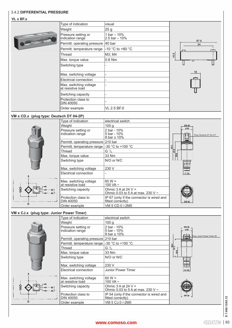
VM x CJ.x (plug type: Junior Power Timer)electrical switch100 g2 bar - 10%5 bar - 10% 8 bar ± 10%210 bar-30 °C to +100 °C G 1/2
33 NmN/O or N/C
230 V Junior Power Timer
60 W =100 VA ~Ohmic 3 A at 24 V =Ohmic 0.03 to 5 A at max. 230 V ~IP 54 (only if the connector is wired and fi tted correctly)VM 5 CJ.0 /-2M0
Plug: Junior Power Timer 2P
Type of indicationWeightPressure setting or indication range
Permitt. operating pressurePermitt. temperature rangeThreadMax. torque valueSwitching type
Max. switching voltageElectrical connection
Max. switching voltage at resistive loadSwitching capacity
Protection class to DIN 40050Order example
VM x CD.x (plug type: Deutsch DT 04-2P)electrical switch100 g2 bar - 10%5 bar - 10% 8 bar ± 10%210 bar-30 °C to +100 °C G 1/2
33 NmN/O or N/C
230 V -
60 W =100 VA ~Ohmic 3 A at 24 V =Ohmic 0.03 to 5 A at max. 230 V ~IP 67 (only if the connector is wired and fi tted correctly)VM 5 CD.0 /-2M0
3.4.2 DIFFERENTIAL PRESSURE
Plug: Deutsch DT 04-2-P
VL x BF.x Type of indication visualWeight 25 gPressure setting or indication range
1 bar – 10%2.5 bar – 10%
Permitt. operating pressure 40 barPermitt. temperature range -10 °C to +80 °C Thread M3; M4Max. torque value 0.6 NmSwitching type -
Max. switching voltage -Electrical connection -Max. switching voltage at resistive load
-
Switching capacity -Protection class to DIN 40050 -
Order example VL 2.5 BF.0
www.comoso.com

94
E 7.
050.
13/0
3.12
VM x CM.x Type of indication electrical switchWeight 70 gPressure setting or indication range
2 bar – 10%5 bar – 10%8 bar ± 10%
Permitt. operating pressure 210 barPermitt. temperature range -10 °C to +100 °C Thread G 1/2
Max. torque value 33 NmSwitching type N/C or N/O
(change-over contacts)Max. switching voltage 24 V Electrical connection Male connection
M12 x 1Max. switching voltage at resistive load
60 W =100 VA ~
Switching capacity ohmic 2.5 A at 24 V =ohmic 2.5 A at 42 V ~
Protection class to DIN 40050
IP 67 (only if the connector is wired and fi tted correctly)
Order example VM 2 CM.0
VM x M.x Type of indication single pole (ground switching)Weight 31 gPressure setting or indication range
2 bar ± 15%
Permitt. operating pressure 210 barPermitt. temperature range -30 °C to +100 °C Thread G 1/2
Max. torque value 33 NmSwitching type N/O or N/C
Max. switching voltage 24VElectrical connection -
Max. switching voltage at resistive load
-
Switching capacity -Protection class to DIN 40050 terminals IP00
Order example VM 2 M.0
Type of indicationWeightPressure setting or indication range
Permitt. operating pressurePermitt. temperature rangeThreadMax. torque valueSwitching type
Max. switching voltageElectrical connection
Max. switching voltage at resistive loadSwitching capacity
Protection class to DIN 40050Order example
VD x CJ.x (plug type: Junior Power Timer)electrical switch200 g2 bar - 10%5 bar - 10% 8 bar ± 10%420 bar-30 °C to +100 °C G 1/2
100 NmN/O or N/C
230 V Junior Power Timer
60 W =100 VA ~Ohmic 3 A at 24 V =Ohmic 0.03 to 5 A at max. 230 V ~IP 54 (only if the connector is wired and fi tted correctly)VD 5 CJ.0 /-2M0
Plug: Junior Power Timer 2P
www.comoso.com

95
E 7.
050.
13/0
3.12
VD x LEM.xType of indication Visual, red pin
and electrical switch1 switching contact at 100% of the pressure setting
Weight 350 gPressure setting or indication range
2 bar – 10%5 bar – 10%8 bar – 10%
Permitt. operating pressure 420 barPermitt. temperature range -10 °C to +100 °C Thread G 1/2 Max. torque value 50 NmSwitching type N/C or N/O contacts
Reed contacts (change-over contacts)Max. switching voltage 24VElectrical connection Male connection
M12 x 1Max. switching voltage at resistive load
15 W =max. 15 VA ~
Switching capacity ohmic 1 A at 15 V =ohmic 1 A at 15 V ~
Protection class to DIN 40050
IP 65
Order example VD 5 LEM.0
www.comoso.com

96
E 7.
050.
13/0
3.12
Type of indicationWeightPressure setting or indication rangePermitt. operating pressurePermitt. temperature rangeThreadMax. torque
Switching type
Max. switching voltage
Electrical connection
Max. switching voltage at resistive loadSwitching capacity
Protection class to DIN 40050Order example
VR x B.x (ATEX) Can be used on aluminium fi lters up to Zone 1
3.5 INDICATORS IN ACCORDANCE WITH ATEX DIRECTIVE3.5.1 RETURN LINE
Type of indicationWeightPressure setting or indication rangePermitt. operating pressurePermitt. temperature rangeThreadMax. torque
Switching type
Max. switching voltage
Electrical connection
Max. switching voltage at resistive loadSwitching capacity
Protection class to DIN 40050Order example
VR x B.x (ATEX) Can be used on steel/cast iron fi lters up to Zone 1
visual, red pin44 g2 bar - 0.2 bar
7 bar-30 °C to +100 °C G 1/2
15 Nm
-
-
-
-
-
-
VR 2 B.0 /-2GC
visual, red pin44 g2 bar - 0.2 bar
7 bar-30 °C to +100 °C G 1/2
15 Nm
-
-
-
-
-
-
VR 2 B.0 /-2GC-SO174
Type of indicationWeightPressure setting or indication rangePermitt. operating pressurePermitt. temperature rangeThreadMax. torque
Switching type
Max. switching voltage
Electrical connection
Max. switching voltage at resistive loadSwitching capacity
Protection class to DIN 40050Order example
VMF x C.x /-Ex2Gelectrical switch270 g2 bar ± 0.3 bar
200 bar-10 °C to +100 °C G 1/8
15 Nm
N/C or N/O (change-over contacts)250 V
Cable connection PG 9Cable length 2 m62.5 W =250 VA ~Ohmic 0.25 A at 250 V =Ohmic 1 A at 250 V ~
II 2G EEx d IIC T6 / T5
VMF 2 C.0 /-Ex2G
www.comoso.com

97
E 7.
050.
13/0
3.12
Type of indicationWeightPressure setting or indication rangePermitt. operating pressurePermitt. temperature rangeThreadMax. torque
Switching type
Max. switching voltage
Electrical connection
Max. switching voltage at resistive loadSwitching capacity
Protection class to DIN 40050Order example
VR x C.x /-Ex2Gelectrical switch340 g2 bar ± 0.3 bar
40 bar-10 °C to +100 °C G 1/2
30 Nm
N/C or N/O (change-over contacts)250 V
Cable connection PG 9Cable length 2 m62.5 W =250 VA ~Ohmic 0.25 A at 250 V =Ohmic 1 A at 250 V ~
II 2G Ex d IIC T6 / T5
VR 2 C.0 /-Ex2G
Type of indicationWeightPressure setting or indication rangePermitt. operating pressurePermitt. temperature rangeThreadMax. torque
Switching type
Max. switching voltage
Electrical connection
Max. switching voltage at resistive loadSwitching capacity
Protection class to DIN 40050Order example
VR x C.x (ATEX) Can be used on fi lters up to Zone 1 *electrical switch340 g2 bar ± 0.3 bar
40 bar-30 °C to +100 °C G 1/2
30 Nm
N/C or N/O (change-over contacts)*
Male connection M20Female connector to DIN 43650*
*
IP 65 (only if the connector is wired and fi tted correctly)VR 2 C.1 /-2GBC
* The clogging indicator is simple electrical operating equipment according to DIN EN 60079-14 and may only be used in intrinsically safe circuits (supplied with manufacturer's declaration and operating instructions).
www.comoso.com

98
E 7.
050.
13/0
3.12
Type of indication
WeightPressure setting or indication rangePermitt. operating pressurePermitt. temperature rangeThreadMax. torque valueSwitching type
Max. switching voltage
Electrical connection
Max. switching voltage at resistive loadSwitching capacity
Protection class to DIN 40050Order example
VM x B.x (ATEX) Can be used on aluminium fi lters up to Zone 13.5.2 DIFFERENTIAL PRESSURE
Type of indication
WeightPressure setting or indication rangePermitt. operating pressurePermitt. temperature rangeThreadMax. torque valueSwitching type
Max. switching voltage
Electrical connection
Max. switching voltage at resistive loadSwitching capacity
Protection class to DIN 40050Order example
VD x B.x (ATEX) Can be used on fi lters up to Zone 1
Visual, red/green band Automatic reset110 g5 bar - 10% 8 bar ± 10%210 bar-30 °C to +100 °C G 1/2
33 Nm-
-
-
-
-
-
VM 5 B.1 /-2GC
Visual, red/green band Automatic reset110 g5 bar - 10% 8 bar ± 10%420 bar-30 °C to +100 °C G 1/2
100 Nm-
-
-
-
-
-
VD 5 B.1 /-2GC
VD x C.x /-2GEXDIICType of indication electrical switchWeight from 600 gPressure setting or indication range
2 bar – 10%5 bar – 10%8 bar ± 10%
Permitt. operating pressure 420 barPermitt. temperature range -20 °C to +60 °C Thread G 1/2
Max. torque value 100 NmSwitching type Change-over
Max. switching voltage 250 V Electrical connection Cable connection
Max. switching voltage at resistive load
60 W =100 VA ~
Switching capacity ohmic 3 A at 24 V =ohmic 0.03 A to 5 A at 250 V ~
Protection class to DIN 40050 IP 66
Order example VD 2 C.1 /-2GEXDIIC
.x /-2GEXDIIC
www.comoso.com

99
E 7.
050.
13/0
3.12
Type of indicationWeightPressure setting or indication range
Permitt. operating pressurePermitt. temperature rangeThreadMax. torque valueSwitching type
Max. switching voltage
Electrical connection
Max. switching voltage at resistive loadSwitching capacity
Protection class to DIN 40050Order example
VD x C.x (ATEX) Can be used on fi lters up to Zone 1 *electrical switch120 g2 bar - 10%5 bar - 10% 8 bar ± 10%420 bar-30 °C to +100 °C G 1/2
100 NmN/C or N/O (change-over contacts)*
Male connection M20Female connector to DIN 43650*
*
IP 65 (only if the connector is wired and fi tted correctly)VD 5 C.0 /-2GBC-SO135
Type of indicationWeightPressure setting or indication range
Permitt. operating pressurePermitt. temperature rangeThreadMax. torque valueSwitching type
Max. switching voltage
Electrical connection
Max. switching voltage at resistive loadSwitching capacity
Protection class to DIN 40050Order example
VM x C.x (ATEX) Can be used on aluminium fi lters up to Zone 1 *electrical switch120 g2 bar - 10%5 bar - 10% 8 bar ± 10%210 bar-30 °C to +100 °C G 1/2
33 NmN/C or N/O (change-over contacts)*
Male connection M20Female connector to DIN 43650*
*
IP 65 (only if the connector is wired and fi tted correctly)VM 5 C.0 /-2GBC-SO135
* The clogging indicator is simple electrical operating equipment according to DIN EN 60079-14 and may only be used in intrinsically safe circuits (supplied with manufacturer's declaration and operating instructions).
www.comoso.com

100
E 7.
050.
13/0
3.12
Type of indicationWeightPressure setting or indication range
Permitt. operating pressurePermitt. temperature rangeThreadMax. torque valueSwitching type
Max. switching voltage
Electrical connection
Max. switching voltage at resistive loadSwitching capacity
Protection class to DIN 40050Order example
VM x C.x (UL)
3.6 INDICATORS WITH UL OR CSA APPROVAL3.6.1 DIFFERENTIAL PRESSURE
Type of indicationWeightPressure setting or indication range
Permitt. operating pressurePermitt. temperature rangeThreadMax. torque valueSwitching type
Max. switching voltage
Electrical connection
Max. switching voltage at resistive loadSwitching capacity
Protection class to DIN 40050Order example
VD x C.x (UL)
Type of indication
WeightPressure setting or indication range
Permitt. operating pressurePermitt. temperature rangeThreadMax. torque valueSwitching type
Max. switching voltage
Electrical connection
Max. switching voltage at resistive loadSwitching capacity
Protection class to DIN 40050Order example
VM x D.x /-L... (UL)
electrical switch120 g2 bar - 10%5 bar - 10% 8 bar ± 10%210 bar-30 °C to +100 °C G 1/2
33 NmN/C or N/O (change-over contacts)115 V
Male connection M20Female connector to DIN 4365060 W =100 VA ~ohmic 3 A at 24 V =
IP 65 (only if the connector is wired and fi tted correctly)VM 5 C.0 /-CRUUS
electrical switch120 g2 bar - 10%5 bar - 10% 8 bar ± 10%420 bar-30 °C to +100 °C G 1/2
100 NmN/C or N/O (change-over contacts)115 V
Male connection M20Female connector to DIN 4365060 W =100 VA ~ohmic 3 A at 24 V =
IP 65 (only if the connector is wired and fi tted correctly)VD 5 C.0 /-CRUUS
visual indicator and electrical switch150 g2 bar - 10%5 bar - 10% 8 bar ± 10%210 bar-30 °C to +100 °C G 1/2
33 NmN/C or N/O (change-over contacts)24, 48, 110 Vdepending on the type of light insertMale connection M20Female connector to DIN 4365060 W =100 VA ~ohmic 3 A at 24 V =
IP 65 (only if the connector is wired and fi tted correctly)VM 5 D.0 /-L24-CRUUS
www.comoso.com

101
E 7.
050.
13/0
3.12
VR x C.x (CSA)Type of indication electrical switchWeight 340 gPressure setting or indication range
2 bar – 0.3 bar
Permitt. operating pressure 40 barPermitt. temperature range -30 °C to +100 °C Thread G 1/2 Max. torque value 30 NmSwitching type N/C or N/O,
(change-over contacts)Max. switching voltage 230 V Electrical connection Male connection PG 9
Female connector to DIN 43650Max. switching voltage at resistive load
250 W =300 VA ~
Switching capacity ohmic 4 A at 24 Vohmic 0.3 to 4 A at max. 230 V ~
Protection class to DIN 40050
IP 65 (only if the connector is wired and fi tted correctly)
Order example VR 2 C.0 /-CSA
Type of indication
WeightPressure setting or indication rangePermitt. operating pressurePermitt. temperature rangeThreadMax. torque valueSwitching type
Max. switching voltage
Electrical connection
Max. switching voltage at resistive loadSwitching capacity
Protection class to DIN 40050Order example
VD x D.x /-L... (UL)visual indicator and electrical switch250 g5 bar - 10% 8 bar ± 10%420 bar-30 °C to +100 °C G 1/2
100 NmN/C or N/O (change-over contacts)24, 48, 110 Vdepending on the type of light insertMale connection M20Female connector to DIN 4365060 W =100 VA ~ohmic 3 A at 24 V =
IP 65 (only if the connector is wired and fi tted correctly)VD 5 D.0 /-L24-CRUUS
3.6.2 RETURN LINE
www.comoso.com
102
E 7.
050.
13/0
3.12
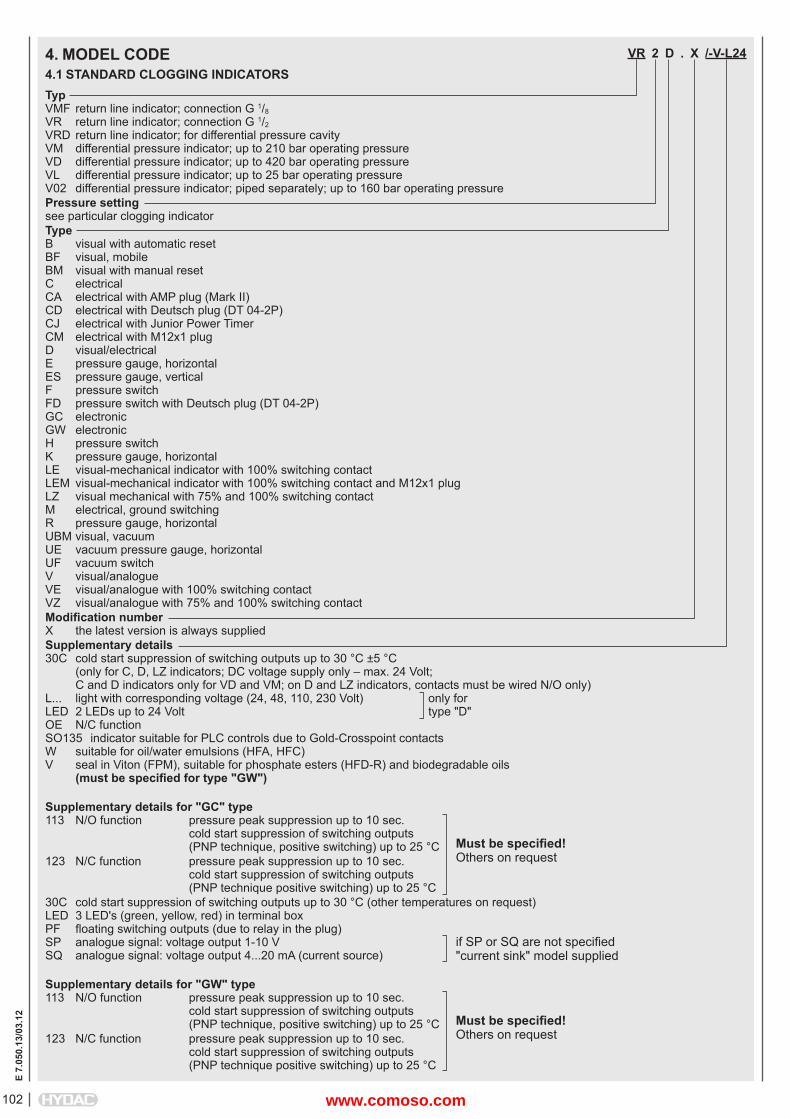
VR 2 D . X /-V-L24
TypVMF return line indicator; connection G 1/8
VR return line indicator; connection G 1/2
VRD return line indicator; for differential pressure cavityVM differential pressure indicator; up to 210 bar operating pressureVD differential pressure indicator; up to 420 bar operating pressureVL differential pressure indicator; up to 25 bar operating pressureV02 differential pressure indicator; piped separately; up to 160 bar operating pressurePressure settingsee particular clogging indicatorTypeB visual with automatic resetBF visual, mobileBM visual with manual resetC electricalCA electrical with AMP plug (Mark II)CD electrical with Deutsch plug (DT 04-2P)CJ electrical with Junior Power TimerCM electrical with M12x1 plugD visual/electricalE pressure gauge, horizontalES pressure gauge, verticalF pressure switchFD pressure switch with Deutsch plug (DT 04-2P)GC electronicGW electronicH pressure switchK pressure gauge, horizontalLE visual-mechanical indicator with 100% switching contactLEM visual-mechanical indicator with 100% switching contact and M12x1 plugLZ visual mechanical with 75% and 100% switching contactM electrical, ground switchingR pressure gauge, horizontalUBM visual, vacuumUE vacuum pressure gauge, horizontalUF vacuum switchV visual/analogueVE visual/analogue with 100% switching contactVZ visual/analogue with 75% and 100% switching contactModifi cation numberX the latest version is always suppliedSupplementary details30C cold start suppression of switching outputs up to 30 °C ±5 °C (only for C, D, LZ indicators; DC voltage supply only – max. 24 Volt; C and D indicators only for VD and VM; on D and LZ indicators, contacts must be wired N/O only)L... light with corresponding voltage (24, 48, 110, 230 Volt) only forLED 2 LEDs up to 24 Volt type "D" OE N/C functionSO135 indicator suitable for PLC controls due to Gold-Crosspoint contactsW suitable for oil/water emulsions (HFA, HFC)V seal in Viton (FPM), suitable for phosphate esters (HFD-R) and biodegradable oils (must be specifi ed for type "GW")
Supplementary details for "GC" type113 N/O function pressure peak suppression up to 10 sec. cold start suppression of switching outputs (PNP technique, positive switching) up to 25 °C123 N/C function pressure peak suppression up to 10 sec. cold start suppression of switching outputs (PNP technique positive switching) up to 25 °C30C cold start suppression of switching outputs up to 30 °C (other temperatures on request)LED 3 LED's (green, yellow, red) in terminal boxPF fl oating switching outputs (due to relay in the plug)SP analogue signal: voltage output 1-10 VSQ analogue signal: voltage output 4...20 mA (current source)
Supplementary details for "GW" type113 N/O function pressure peak suppression up to 10 sec. cold start suppression of switching outputs (PNP technique, positive switching) up to 25 °C123 N/C function pressure peak suppression up to 10 sec. cold start suppression of switching outputs (PNP technique positive switching) up to 25 °C
4. MODEL CODE4.1 STANDARD CLOGGING INDICATORS
Must be specifi ed!Others on request
Must be specifi ed!Others on request
if SP or SQ are not specifi ed"current sink" model supplied
www.comoso.com

103
E 7.
050.
13/0
3.12
Supplementary details for "LZ" typeAV plug and connector to AUDI, VW specifi cationBO plug and connector to BMW, Opel, Ford specifi cationBO-LED as for BO, but with progressive LED stripCN electrical connection, 1 connector DIN 43651 with 3 LEDs (to CNOMO specifi cation NF E 48-700)DB electrical connection, 1 connector to DIN 43651 with 3 LEDs (to Daimler-Benz and BMW specifi cation)D4C plug and connector to Daimler-Chrysler specifi cation with cold start suppression 30 °C
Supplementary details to "ATEX" type2GC for visual indicator type "B" with ATEX certifi cate2GBC for electrical indicator type "C" with ATEX certifi cate (the switch used in the indicator is a passive component according to EN 50020 and can therefore be used in intrinsically safe circuits as simple apparatus in accordance with EN 60079-14)2GEXDIIC for electrical indicator suitable for use in Zone 1 (Category 2), gas atmosphere, Category d (Flameproof Enclosure), Explosive subdivision IIC to ATEX directiveEX2G Ex-protection type for the return line indicator type "C"
Supplementary details for "UL" and "CSA" approvalCRUUS for electrical differential indicator type "C" or visual/electrical indicator type "D" with UL approvalCSA for electrical return line indicator type "C" with CSA approval
www.comoso.com

104
E 7.
050.
13/0
3.12
5. ADAPTERS5.1 TYPES
DesignationPart no.Description
ADAPTER VD-D-S.000318736Extending adapter for differential pressure cavity to HYDAC works standard HN 28-22
DesignationPart no.Description
ADAPTER VD-D+D-S+S.000318732Y-adapter to convert 1 differential pressure cavity into 2 differentialpressure cavities according to HYDAC works standard HN 28-22.
Swivel-type on request!
DesignationPart no.Description
ADAPTER VD-1/4+1/4-W+W.0 /-0040433700404337Test adapter for different pressure cavity according to HYDAC works standard HN 28-22. To test the pressure before and afterthe fi lter element.
Also available without minimess couplings (on request)!
DesignationPart no.Description
ADAPTER VR-R+R-S+S.000318741Y-adapter to convert 1 return line cavityinto 2 return line cavities (G ½ )
Swivel-type on request!
DesignationPart no.Description
ADAPTER V ¼ I-D-S.000318730Connection adapter for piping clogging indicators separately with differentialpressure cavity according to HYDAC works standard HN 28-22.
Two connections G ¼ (one before and one after thefi lter element)
www.comoso.com

105
E 7.
050.
13/0
3.12
DesignationPart no.Description
ADAPTER VD-D+1/4+1/4-S+W+W.000318744Extending adapter for differential pressure cavity according to HYDAC works standard HN 28-22.Also two connections, one before and one after the fi lter element.
DesignationPart no.Description
ADAPTER VF-D-S.0 /-RTOn requestonly for the following fi lters:LFR, LPFR, MDFR, RFLR, RFMR, RKMR, SFFR
ADAPTER VD-D+1/4+1/4-S+W+W.X /-ESB
ConnectionVD differential pressure indicator; connection G ½ VR return line indicator; connection G ½ V¼I differential pressure indicator; connection G ¼ internalVF differential pressure indicator; fl ange type
Ports (several ports are possible!)D differntial pressure cavity G ½ R return line cavity G ½ MF cavity for pressure gauge and pressure switch1/4 cavity G ¼ for Minimess test points (M16 x 1.5)1/8 cavity G 1/8 for Minimess test points (plug-in connection)
Orientation of the portsS verticalW horizontal
Type codeX the latest version is always supplied
Supplementary detailsESB swivel typeV seal in Viton (FPM), suitable for phosphate ester (HFD-R) and biodegradable oils
5.2 MODEL CODEL (= EXAMPLE) 5.3 OTHER EXAMPLESVD-D-S.0
VR-R+R-S+S.0
VD-D+1/4+1/4-S+W+W.0
port
1
port
2
port
3po
rt 1
port
2po
rt 3
CavityNumber:1Type: DOrientation:vertical
connection: VD
PortNumber:2Type: ROrientation:vertical
connection: VD
port
3
connection
port 1
port
2
www.comoso.com

106
E 7.
050.
13/0
3.12
6. DESINA SPECIFICATIONDESINA is a fully comprehensive system intended to bring standardization and decentralization to the fi eld of fl uid technology and to electrical installation of machinery and systems. The system engineering, automotive and supply industries have worked together to draw up specifi cations of the necessary components. DESINA makes use of tried-and-tested solutions, such as open bus systems, standard industrial plugs etc. By standardizing components, interfaces and connection systems, such as a hybrid fi eld bus cable (Cu/LWL), a wide range of different fi eld bus systems can be made compatible on a single physical base.
6.1. TOTAL CONCEPT FOR MACHINE TOOL INSTALLATION
6.2. CLOGGING INDICATORSThe following clogging indicators are approved to DESINA specifi cation:VD 5 LZ.1 /-D4C VR 2.5 LZ. 1 /-D4C VD 5 LZ.1 /-BO VR 2.5 LZ. 1 /-BO VD 5 LZ. 1 /-AV VR 2.5 LZ. 1 /-AV VR 2.5 LZ. 0 /-GM all with M 12 x 1 connector!
The DESINA logo is shown on the type code label of approved clogging indicators.sw
itch
cabi
net
4 x 1.5 mm² and 2 x LWL
"HAN-Q8 or 10E"
www.comoso.com

107
E 7.
050.
13/0
3.12
www.comoso.com

108
E 7.
050.
13/0
3.12
NOTEThe information in this brochure relates to the operating conditions and applications described.For applications or operating conditions not described, please contact the relevant technical department. Subject to technical modifi cations.
HYDAC FILTERTECHNIK GMBHIndustriegebietD-66280 Sulzbach/SaarTel.: 0 68 97 / 509-01Fax: 0 68 97 / 509-300Internet: www.hydac.comE-Mail: fi [email protected]
www.comoso.com