Film Processing Advances - Carl Hanser...
41
Sample Pages Film Processing Advances Herausgegeben von Toshitaka Kanai, Gregory Campbell ISBN (Buch): 978-1-56990-529-6 ISBN (E-Book): 978-1-56990-536-4 For further information and order see http://www.hanser-fachbuch.de/978-1-56990-529-6 or contact your bookseller. © Carl Hanser Verlag, München
Transcript of Film Processing Advances - Carl Hanser...

Sample Pages
Film Processing Advances
Herausgegeben von Toshitaka Kanai, Gregory Campbell
ISBN (Buch): 978-1-56990-529-6
ISBN (E-Book): 978-1-56990-536-4
For further information and order see
http://www.hanser-fachbuch.de/978-1-56990-529-6
or contact your bookseller.
© Carl Hanser Verlag, München

Foreword . . . . . . . . . . . . . . . . . . . . . . . . . . . . . . . . . . . . . . . . . . . . . . . . . . . . . . . . . . . . VII
Contributors . . . . . . . . . . . . . . . . . . . . . . . . . . . . . . . . . . . . . . . . . . . . . . . . . . . . . . . . XV
Preface . . . . . . . . . . . . . . . . . . . . . . . . . . . . . . . . . . . . . . . . . . . . . . . . . . . . . . . . . . . . . . XVII
1 Extruder and Screw Design for Film Processing . . . . . . . . . . . . . . . . . . . 1Mark A. Spalding and Gregory A. Campbell
1.1 The Extrusion Process . . . . . . . . . . . . . . . . . . . . . . . . . . . . . . . . . . . . . . . . . . . . . . . 21.2 Rate Calculation . . . . . . . . . . . . . . . . . . . . . . . . . . . . . . . . . . . . . . . . . . . . . . . . . . . . 91.3 Gels . . . . . . . . . . . . . . . . . . . . . . . . . . . . . . . . . . . . . . . . . . . . . . . . . . . . . . . . . . . . . . 121.4 Troubleshooting Extrusion Processes . . . . . . . . . . . . . . . . . . . . . . . . . . . . . . . . . . . 17
1.4.1 Improper Shutdown of Processing Equipment . . . . . . . . . . . . . . . . . . . . . . 181.4.2 Gel Showers in a Cast Film Process . . . . . . . . . . . . . . . . . . . . . . . . . . . . . . . 191.4.3 Unmixed Gels . . . . . . . . . . . . . . . . . . . . . . . . . . . . . . . . . . . . . . . . . . . . . . . . 211.4.4 Carbon Specks in a Film Product . . . . . . . . . . . . . . . . . . . . . . . . . . . . . . . . . 221.4.5 Rate Limitation Due to a Worn Screw . . . . . . . . . . . . . . . . . . . . . . . . . . . . . 23
2 Kinematics, Dynamics, Crystallization, and Thermal Characteristics and Their Relationship to Physical Properties of Blown Film . . . . . . . 27G. A. Campbell
2.1 Abstract . . . . . . . . . . . . . . . . . . . . . . . . . . . . . . . . . . . . . . . . . . . . . . . . . . . . . . . . . . 282.2 Introduction . . . . . . . . . . . . . . . . . . . . . . . . . . . . . . . . . . . . . . . . . . . . . . . . . . . . . . . 292.3 Real-Time Crystallization of the Blown Film Process . . . . . . . . . . . . . . . . . . . . . . . 302.4 Experiments . . . . . . . . . . . . . . . . . . . . . . . . . . . . . . . . . . . . . . . . . . . . . . . . . . . . . . . 332.5 Process Data Analysis . . . . . . . . . . . . . . . . . . . . . . . . . . . . . . . . . . . . . . . . . . . . . . . 342.6 SALS Image Analysis . . . . . . . . . . . . . . . . . . . . . . . . . . . . . . . . . . . . . . . . . . . . . . . . 372.7 Nucleation with High-Density Polyethylene . . . . . . . . . . . . . . . . . . . . . . . . . . . . . . 422.8 Experiments . . . . . . . . . . . . . . . . . . . . . . . . . . . . . . . . . . . . . . . . . . . . . . . . . . . . . . . 432.9 Results . . . . . . . . . . . . . . . . . . . . . . . . . . . . . . . . . . . . . . . . . . . . . . . . . . . . . . . . . . . 432.10 Temperature Measurement and Heat Transfer from the Blown Film Bubble . . . . . 462.11 Measuring Film Emissivity and Film Thickness . . . . . . . . . . . . . . . . . . . . . . . . . . . 482.12 Film Average Bulk Temperature and Surface Temperature . . . . . . . . . . . . . . . . . . . 512.13 Experimental Evaluation of the Bubble Heat Transfer Coefficient . . . . . . . . . . . . . 53
Contents

X Contents
2.14 Results and Discussion . . . . . . . . . . . . . . . . . . . . . . . . . . . . . . . . . . . . . . . . . . . . . . . 572.15 Correlating of MD and TD Properties of Blown Film . . . . . . . . . . . . . . . . . . . . . . . . 62
3 Multilayer Die Design and Film Structures . . . . . . . . . . . . . . . . . . . . . . . . 67Karen Xiao and Martin Zatloukal
3.1 Background . . . . . . . . . . . . . . . . . . . . . . . . . . . . . . . . . . . . . . . . . . . . . . . . . . . . . . . 683.1.1 Materials . . . . . . . . . . . . . . . . . . . . . . . . . . . . . . . . . . . . . . . . . . . . . . . . . . . 703.1.2 Film Structures . . . . . . . . . . . . . . . . . . . . . . . . . . . . . . . . . . . . . . . . . . . . . . 713.1.3 Equipment Producers . . . . . . . . . . . . . . . . . . . . . . . . . . . . . . . . . . . . . . . . . 72
3.2 Basic Coextrusion Film Die Types . . . . . . . . . . . . . . . . . . . . . . . . . . . . . . . . . . . . . . 733.2.1 Manufacturing Method . . . . . . . . . . . . . . . . . . . . . . . . . . . . . . . . . . . . . . . . 733.2.2 Cast Die Types . . . . . . . . . . . . . . . . . . . . . . . . . . . . . . . . . . . . . . . . . . . . . . . 763.2.3 Blown Film Die Types . . . . . . . . . . . . . . . . . . . . . . . . . . . . . . . . . . . . . . . . . 79
3.3 Interfacial Instabilities . . . . . . . . . . . . . . . . . . . . . . . . . . . . . . . . . . . . . . . . . . . . . . . 853.3.1 Merging Area, Wave Type of Interfacial Instabilities, and the
TNSD Sign Stability Criterion . . . . . . . . . . . . . . . . . . . . . . . . . . . . . . . . . . . 873.3.1.1 The Effect of Die Design on the Wave Type of Interfacial
Instabilities . . . . . . . . . . . . . . . . . . . . . . . . . . . . . . . . . . . . . . . . . . 933.3.1.2 The Role of Extensional Viscosities . . . . . . . . . . . . . . . . . . . . . . . . 94
3.3.2 Die Exit Region, Zigzag Interfacial Instabilities, and the Role of Polymer Processing Aids . . . . . . . . . . . . . . . . . . . . . . . . . . . . . . . . . . . . . . . . . . . . . . 96
3.3.3 Development of Interfacial Instabilities in Cast Film and Film Blowing of LDPEs . . . . . . . . . . . . . . . . . . . . . . . . . . . . . . . . . . . . . . . . . . . . . . . . . . . . 100
3.4 Flow Analysis for Flat Spiral Die . . . . . . . . . . . . . . . . . . . . . . . . . . . . . . . . . . . . . . . 102
4 Die Flow Analysis and Mathematical Modeling of Film Blowing . . . . 111J. Vlachopoulos and V. Sidiropoulos
4.1 Introduction . . . . . . . . . . . . . . . . . . . . . . . . . . . . . . . . . . . . . . . . . . . . . . . . . . . . . . . 1124.2 Die Flow Analysis . . . . . . . . . . . . . . . . . . . . . . . . . . . . . . . . . . . . . . . . . . . . . . . . . . . 1134.3 Computer-Aided Die Design . . . . . . . . . . . . . . . . . . . . . . . . . . . . . . . . . . . . . . . . . . . 1174.4 Modeling of Bubble Forming . . . . . . . . . . . . . . . . . . . . . . . . . . . . . . . . . . . . . . . . . . 1194.5 Effect of Viscoelasticity . . . . . . . . . . . . . . . . . . . . . . . . . . . . . . . . . . . . . . . . . . . . . . 1224.6 Modeling of Bubble Cooling . . . . . . . . . . . . . . . . . . . . . . . . . . . . . . . . . . . . . . . . . . . 1234.7 Bubble Collapsing . . . . . . . . . . . . . . . . . . . . . . . . . . . . . . . . . . . . . . . . . . . . . . . . . . 1274.8 Critique on Flow Analysis and Bubble Modeling . . . . . . . . . . . . . . . . . . . . . . . . . . 1284.9 Concluding Remarks . . . . . . . . . . . . . . . . . . . . . . . . . . . . . . . . . . . . . . . . . . . . . . . . 130
5 T-die Film Casting . . . . . . . . . . . . . . . . . . . . . . . . . . . . . . . . . . . . . . . . . . . . . . . . 133Toshitaka Kanai
5.1 Introduction . . . . . . . . . . . . . . . . . . . . . . . . . . . . . . . . . . . . . . . . . . . . . . . . . . . . . . . 1345.2 Film Casting Process . . . . . . . . . . . . . . . . . . . . . . . . . . . . . . . . . . . . . . . . . . . . . . . . 1355.3 Theoretical Analysis of Film Deformation under a Steady State . . . . . . . . . . . . . . . 1355.4 Deformation Behavior of T-die Casting . . . . . . . . . . . . . . . . . . . . . . . . . . . . . . . . . . 137
Contents XI
5.5 Draw Resonance . . . . . . . . . . . . . . . . . . . . . . . . . . . . . . . . . . . . . . . . . . . . . . . . . . . . 1415.6 Film Breakage . . . . . . . . . . . . . . . . . . . . . . . . . . . . . . . . . . . . . . . . . . . . . . . . . . . . . . 1435.7 Necking Phenomenon . . . . . . . . . . . . . . . . . . . . . . . . . . . . . . . . . . . . . . . . . . . . . . . 1445.8 Surface Roughness Caused by Shark Skin and Melt Fracture . . . . . . . . . . . . . . . . 1475.9 Film Physical Properties . . . . . . . . . . . . . . . . . . . . . . . . . . . . . . . . . . . . . . . . . . . . . 151
5.9.1 Influence of Process Conditions . . . . . . . . . . . . . . . . . . . . . . . . . . . . . . . . . . 1515.9.2 Influence of Polymer Design . . . . . . . . . . . . . . . . . . . . . . . . . . . . . . . . . . . . 152
5.9.2.1 Branching and Properties of LLDPE . . . . . . . . . . . . . . . . . . . . . . . 1535.9.2.2 Impact Strength . . . . . . . . . . . . . . . . . . . . . . . . . . . . . . . . . . . . . . . 1535.9.2.3 Heat Seal Temperature . . . . . . . . . . . . . . . . . . . . . . . . . . . . . . . . . 1555.9.2.4 Blocking and Slippage . . . . . . . . . . . . . . . . . . . . . . . . . . . . . . . . . 1565.9.2.5 Transparency . . . . . . . . . . . . . . . . . . . . . . . . . . . . . . . . . . . . . . . . . 1575.9.2.6 Summary of Film Physical Properties . . . . . . . . . . . . . . . . . . . . . 157
5.10 Bleeding of Additives in a Polypropylene Film . . . . . . . . . . . . . . . . . . . . . . . . . . . . 158
6 An Overview of Molten Polymer Drawing Instabilities . . . . . . . . . . . . . 163Jean-Francois Agassant and Yves Demay
6.1 Introduction . . . . . . . . . . . . . . . . . . . . . . . . . . . . . . . . . . . . . . . . . . . . . . . . . . . . . . . 1646.2 Experiments . . . . . . . . . . . . . . . . . . . . . . . . . . . . . . . . . . . . . . . . . . . . . . . . . . . . . . . 1656.3 Modeling Strategy: Constant Width Cast Film Process . . . . . . . . . . . . . . . . . . . . . . 1716.4 Cast Film Process . . . . . . . . . . . . . . . . . . . . . . . . . . . . . . . . . . . . . . . . . . . . . . . . . . . 174
6.4.1 Influence of Cooling . . . . . . . . . . . . . . . . . . . . . . . . . . . . . . . . . . . . . . . . . . . 1746.4.2 Influence of the Neck-In Phenomenon . . . . . . . . . . . . . . . . . . . . . . . . . . . . . 1756.4.3 Validity of the Membrane Model: 2-D Transverse Simulation . . . . . . . . . . 1776.4.4 Influence of Rheology . . . . . . . . . . . . . . . . . . . . . . . . . . . . . . . . . . . . . . . . . . 180
6.5 Fiber Spinning . . . . . . . . . . . . . . . . . . . . . . . . . . . . . . . . . . . . . . . . . . . . . . . . . . . . . 1826.6 Film Blowing . . . . . . . . . . . . . . . . . . . . . . . . . . . . . . . . . . . . . . . . . . . . . . . . . . . . . . . 1836.7 Conclusions . . . . . . . . . . . . . . . . . . . . . . . . . . . . . . . . . . . . . . . . . . . . . . . . . . . . . . . 187
7 Biaxial Oriented Film Technology . . . . . . . . . . . . . . . . . . . . . . . . . . . . . . . . . 193J. Breil
7.1 Introduction . . . . . . . . . . . . . . . . . . . . . . . . . . . . . . . . . . . . . . . . . . . . . . . . . . . . . . . 1947.2 Biaxial Oriented Film Lines . . . . . . . . . . . . . . . . . . . . . . . . . . . . . . . . . . . . . . . . . . . 196
7.2.1 Sequential Film Lines . . . . . . . . . . . . . . . . . . . . . . . . . . . . . . . . . . . . . . . . . 1967.2.1.1 Extrusion . . . . . . . . . . . . . . . . . . . . . . . . . . . . . . . . . . . . . . . . . . . . 1987.2.1.2 Casting Machine . . . . . . . . . . . . . . . . . . . . . . . . . . . . . . . . . . . . . . 2017.2.1.3 Machine Direction Orienter (MDO) . . . . . . . . . . . . . . . . . . . . . . . . 2037.2.1.4 Transverse Direction Orienter (TDO) . . . . . . . . . . . . . . . . . . . . . . 2057.2.1.5 Pull Roll Stand . . . . . . . . . . . . . . . . . . . . . . . . . . . . . . . . . . . . . . . . 2087.2.1.6 Winder . . . . . . . . . . . . . . . . . . . . . . . . . . . . . . . . . . . . . . . . . . . . . . 209
7.2.2 Simultaneous Stretching Lines . . . . . . . . . . . . . . . . . . . . . . . . . . . . . . . . . . 2117.3 Process Control . . . . . . . . . . . . . . . . . . . . . . . . . . . . . . . . . . . . . . . . . . . . . . . . . . . . . 2177.4 Development Environment for Biaxial Oriented Films . . . . . . . . . . . . . . . . . . . . . . 2227.5 Market for Biaxial Oriented Films . . . . . . . . . . . . . . . . . . . . . . . . . . . . . . . . . . . . . . 225

XII Contents
8 Biaxially Oriented Tentering Film . . . . . . . . . . . . . . . . . . . . . . . . . . . . . . . . . 231Toshitaka Kanai
8.1 Introduction . . . . . . . . . . . . . . . . . . . . . . . . . . . . . . . . . . . . . . . . . . . . . . . . . . . . . . . 2328.2 Tentering Process . . . . . . . . . . . . . . . . . . . . . . . . . . . . . . . . . . . . . . . . . . . . . . . . . . . 2328.3 Biaxially Oriented Tentering Machine . . . . . . . . . . . . . . . . . . . . . . . . . . . . . . . . . . 2348.4 Theoretical and Experimental Analyses and Polymer Design for
Biaxially Oriented Film . . . . . . . . . . . . . . . . . . . . . . . . . . . . . . . . . . . . . . . . . . . . . . 2388.4.1 Cooling Process Analysis . . . . . . . . . . . . . . . . . . . . . . . . . . . . . . . . . . . . . . 2398.4.2 Stretching Process Analysis . . . . . . . . . . . . . . . . . . . . . . . . . . . . . . . . . . . . . 241
8.5 Visualization of Stretching Process . . . . . . . . . . . . . . . . . . . . . . . . . . . . . . . . . . . . . 2538.6 Film Physical Properties of Biaxially Oriented Film . . . . . . . . . . . . . . . . . . . . . . . . 2578.7 Surface Roughness Control of Stretched Film . . . . . . . . . . . . . . . . . . . . . . . . . . . . . 260
9 Structure Development in Uniaxial and Biaxial Film Stretching . . . . 263T. Kikutani and W. Takarada
9.1 Introduction . . . . . . . . . . . . . . . . . . . . . . . . . . . . . . . . . . . . . . . . . . . . . . . . . . . . . . . 2649.2 Equipment for In Situ Measurement of Optical Retardation . . . . . . . . . . . . . . . . . . 2659.3 In Situ Measurement during Batch-Type Film Stretching Experiments . . . . . . . . . 267
9.3.1 Variation of In-Plane Birefringence during Uniaxial Stretching and Relaxation Processes . . . . . . . . . . . . . . . . . . . . . . . . . . . . . . . . . . . . . . . . . . 267
9.3.2 Three-Dimensional Analysis of Birefringence Development in Film Stretching . . . . . . . . . . . . . . . . . . . . . . . . . . . . . . . . . . . . . . . . . . . . . . . 2689.3.2.1 Uniaxial Elongation . . . . . . . . . . . . . . . . . . . . . . . . . . . . . . . . . . . . 2689.3.2.2 Planar Elongation . . . . . . . . . . . . . . . . . . . . . . . . . . . . . . . . . . . . . 2699.3.2.3 Simultaneous Biaxial Elongation . . . . . . . . . . . . . . . . . . . . . . . . . . 270
9.3.3 Stress versus Birefringence Behavior . . . . . . . . . . . . . . . . . . . . . . . . . . . . . 2719.4 Analysis of Sequential Biaxial Elongation . . . . . . . . . . . . . . . . . . . . . . . . . . . . . . . . 273
9.4.1 Theoretical Prediction for Sequential Biaxial Elongation . . . . . . . . . . . . . . 2739.4.2 Off-Line Analysis of Film Samples from the Sequential Biaxial
Stretching Process . . . . . . . . . . . . . . . . . . . . . . . . . . . . . . . . . . . . . . . . . . . . 2759.4.2.1 Birefringence . . . . . . . . . . . . . . . . . . . . . . . . . . . . . . . . . . . . . . . . . 2759.4.2.2 WAXD Analysis . . . . . . . . . . . . . . . . . . . . . . . . . . . . . . . . . . . . . . . 278
9.5 Intrinsic Birefringence for Various Orientation Modes . . . . . . . . . . . . . . . . . . . . . . 2819.6 Concluding Remarks . . . . . . . . . . . . . . . . . . . . . . . . . . . . . . . . . . . . . . . . . . . . . . . . 282
10 Double Bubble Tubular Film Extrusion . . . . . . . . . . . . . . . . . . . . . . . . . . . . 285Toshitaka Kanai
10.1 Introduction . . . . . . . . . . . . . . . . . . . . . . . . . . . . . . . . . . . . . . . . . . . . . . . . . . . . . . . 28610.2 Double Bubble Tubular Machine . . . . . . . . . . . . . . . . . . . . . . . . . . . . . . . . . . . . . . . 28710.3 Theoretical Analysis of Double Bubble Tubular Film Process . . . . . . . . . . . . . . . . . 287
10.3.1 Theoretical Analysis of Preheating Process and Stretching Process . . . . . . 28710.3.2 Analysis of Stretching Stress . . . . . . . . . . . . . . . . . . . . . . . . . . . . . . . . . . . . 291
10.4 Bubble Deformation Behavior [16] . . . . . . . . . . . . . . . . . . . . . . . . . . . . . . . . . . . . . . 292

Contents XIII
10.5 Film Properties . . . . . . . . . . . . . . . . . . . . . . . . . . . . . . . . . . . . . . . . . . . . . . . . . . . . . 29510.6 Comparison of Double Bubble Tubular Film (DBTF) and Laboratory Tenter
Stretched Film (LTSF) [17] . . . . . . . . . . . . . . . . . . . . . . . . . . . . . . . . . . . . . . . . . . . . . 29610.6.1 Bubble Deformation Behavior and Stretching Stress . . . . . . . . . . . . . . . . . 29610.6.2 Comparison of LLDPE Film Properties of DBTF and LTSF . . . . . . . . . . . . . 299
10.7 Material Design of Polyolefin for Double Bubble Tubular Film . . . . . . . . . . . . . . . . 30110.7.1 Polyethylene [18] . . . . . . . . . . . . . . . . . . . . . . . . . . . . . . . . . . . . . . . . . . . . . 30210.7.2 Polypropylene [19] . . . . . . . . . . . . . . . . . . . . . . . . . . . . . . . . . . . . . . . . . . . . 304
10.8 Thickness Uniformity . . . . . . . . . . . . . . . . . . . . . . . . . . . . . . . . . . . . . . . . . . . . . . . . 30510.9 High Performance Film Produced by Blend and Multilayer Stretching Process . . . 30710.10 Scale-Up Rule . . . . . . . . . . . . . . . . . . . . . . . . . . . . . . . . . . . . . . . . . . . . . . . . . . . . . . 30810.11 Three Different Stretching Processes . . . . . . . . . . . . . . . . . . . . . . . . . . . . . . . . . . . . 31110.12 Conclusions . . . . . . . . . . . . . . . . . . . . . . . . . . . . . . . . . . . . . . . . . . . . . . . . . . . . . . . 311
11 Double Bubble Tubular Film Process and Its Application . . . . . . . . . . 315Masao Takashige
11.1 Introduction . . . . . . . . . . . . . . . . . . . . . . . . . . . . . . . . . . . . . . . . . . . . . . . . . . . . . . . 31611.2 Physical Properties of Biaxial Oriented PA6 Film for Simultaneous Stretching
and Sequential Processing . . . . . . . . . . . . . . . . . . . . . . . . . . . . . . . . . . . . . . . . . . . . 31811.2.1 Stretching Process (Three Technical Methods) . . . . . . . . . . . . . . . . . . . . . . 31811.2.2 Film Physical Properties . . . . . . . . . . . . . . . . . . . . . . . . . . . . . . . . . . . . . . . 320
11.2.2.1 Impact Strength . . . . . . . . . . . . . . . . . . . . . . . . . . . . . . . . . . . . . . 32011.2.2.2 Tensile Properties . . . . . . . . . . . . . . . . . . . . . . . . . . . . . . . . . . . . . 32111.2.2.3 Shrinkage Properties in Hot Water (Shrinkage Patterns) . . . . . . . 32211.2.2.4 Stress-Strain Curve Pattern . . . . . . . . . . . . . . . . . . . . . . . . . . . . . . 323
11.2.3 Wide-Angle X-ray Diffraction Pattern . . . . . . . . . . . . . . . . . . . . . . . . . . . . . 32611.2.4 Polarized Fluorescence . . . . . . . . . . . . . . . . . . . . . . . . . . . . . . . . . . . . . . . . 327
11.3 Easy-Tear Film of Biaxial Oriented PA6/MXD6 Blend by Double Bubble Tubular Film Process . . . . . . . . . . . . . . . . . . . . . . . . . . . . . . . . . . . . . . . . . . . . . . . 32811.3.1 Equipment and Materials . . . . . . . . . . . . . . . . . . . . . . . . . . . . . . . . . . . . . . . 32811.3.2 Blend Ratio (Dry Blending) . . . . . . . . . . . . . . . . . . . . . . . . . . . . . . . . . . . . . 330
11.3.2.1 Stretchability . . . . . . . . . . . . . . . . . . . . . . . . . . . . . . . . . . . . . . . . . 33011.3.2.2 Physical Properties . . . . . . . . . . . . . . . . . . . . . . . . . . . . . . . . . . . . 33111.3.2.3 Easy-Tearing Properties . . . . . . . . . . . . . . . . . . . . . . . . . . . . . . . . . 33311.3.2.4 Observation with TEM . . . . . . . . . . . . . . . . . . . . . . . . . . . . . . . . . . 33611.3.2.5 Observation with SALS . . . . . . . . . . . . . . . . . . . . . . . . . . . . . . . . . 33811.3.2.6 Mechanism of Developed Property . . . . . . . . . . . . . . . . . . . . . . . . 33911.3.2.7 Thickness Uniformity . . . . . . . . . . . . . . . . . . . . . . . . . . . . . . . . . . 339
11.3.3 Kneading Conditions (Premixing) . . . . . . . . . . . . . . . . . . . . . . . . . . . . . . . . 34011.3.3.1 Stretchability (Melting Point of MXD6) . . . . . . . . . . . . . . . . . . . . . 34011.3.3.2 Physical Properties . . . . . . . . . . . . . . . . . . . . . . . . . . . . . . . . . . . . 34211.3.3.3 Structure Analysis . . . . . . . . . . . . . . . . . . . . . . . . . . . . . . . . . . . . . 343
11.4 Summary . . . . . . . . . . . . . . . . . . . . . . . . . . . . . . . . . . . . . . . . . . . . . . . . . . . . . . . . . 344

XIV Contents
12 Highly Transparent Polypropylene Sheets . . . . . . . . . . . . . . . . . . . . . . . . 349Akira Funaki
12.1 Introduction . . . . . . . . . . . . . . . . . . . . . . . . . . . . . . . . . . . . . . . . . . . . . . . . . . . . . . . 35012.2 Influence of Screw Geometry on External Haze of Melted Web . . . . . . . . . . . . . . . 351
12.2.1 Preliminary Extrusion Tests Using Typical and Simple Geometry Screw 35112.2.2 Optimization of Screw Geometry . . . . . . . . . . . . . . . . . . . . . . . . . . . . . . . . . 354
12.3 Influence of Shear Stress in Die on Internal Haze . . . . . . . . . . . . . . . . . . . . . . . . . 35512.4 Analysis of Contributing Factors to Production of Highly Transparent
PP Extrusion Sheets . . . . . . . . . . . . . . . . . . . . . . . . . . . . . . . . . . . . . . . . . . . . . . . . . 35912.4.1 Influence of Isotacticity on Transparency . . . . . . . . . . . . . . . . . . . . . . . . . . 36012.4.2 Influence of Molecular Weight Distribution on Transparency . . . . . . . . . . 36512.4.3 Influence of Addition of Metallocene Linear Low Density Polyethylene
on Transparency . . . . . . . . . . . . . . . . . . . . . . . . . . . . . . . . . . . . . . . . . . . . . 36612.5 Conclusion . . . . . . . . . . . . . . . . . . . . . . . . . . . . . . . . . . . . . . . . . . . . . . . . . . . . . . . . 368
Author Index . . . . . . . . . . . . . . . . . . . . . . . . . . . . . . . . . . . . . . . . . . . . . . . . . . . . . . . . . 371
Subject Index . . . . . . . . . . . . . . . . . . . . . . . . . . . . . . . . . . . . . . . . . . . . . . . . . . . . . . . 377

Foreword
The polymer and plastics industries have had a profound techno-economic impact on society for almost a century. In fact, it has been suggested that the advent and use of polymers and plastics products have represented a revolutionary technologi-cal change. They are used in packaging, furniture, construction materials, automo-tive, aerospace, sporting goods, biomedical, electronics, communications, and so on. More importantly, they have adapted to the ever changing social and technological demands. Thus, many of the current popular products, such as smart phones, com-puters, and other technological innovations would be difficult to contemplate in the absence of polymers. It does not seem likely that the foreseeable future will see a reduction in the important role that polymers and plastics will play in future tech-nological development.
Cognizant of the role that polymers played and will continue to play in our lives, a group of polymer scientists and engineers from various countries around the world founded the Polymer Processing Society (PPS) in March 1985 at the University of Akron, Akron, Ohio, USA. According to its constitution, the goal of the PPS is to fos-ter scientific understanding and technical innovation in polymer processing by pro-viding a discussion forum in the field for the worldwide community of engineers and scientists. Thus, PPS has attempted to achieve this goal using the following mechanisms:
1. Organization of annual and regional conferences rotating among the various regions of the world and the dissemination of technical content of the confer-ences in the form of proceedings.
2. The publication of the International Polymer Processing (IPP) Journal.3. The publication of the Progress in Polymer Processing (PPP) Series.
So far, these activities have allowed the PPS and its members to exchange informa-tion and ideas about the evolution of the principles and methods of polymer science and engineering and their application to the generation of innovative products, pro-cesses and applications.
Since the formation of PPS, eleven PPP volumes have been published. Four distin-guished leaders in the polymer processing field have served as series editors: Leszek Utracki, Warren Baker, Kun Sup Hyun, and James L. White. Last summer at PPS 29 in Nuremberg, Germany, I was asked by the Executive Committee of PPS to serve as

VIII Foreword
PPP series editor. It is my hope, that with the help of the Advisory Editorial Board, our colleagues in the polymer processing field, and Hanser Publications, to publish at the rate of about one book every year. We already have two books under prepara-tion. I encourage prospective authors to contact me or any of the Advisory Board members with their ideas and suggestions.
One of my first tasks has been to follow and expedite the completion of Film Process-ing Advances. This has given me the opportunity to refresh and expand my contacts with the editors, Drs. Kanai and Campbell, whom I have known for many years. As I have done some work in the area of film processing, I always benefited from reading their works and meeting them at conferences. Thus, it was easy to work together with them and with the publisher, Hanser, to set up the necessary mechanisms and procedures for a smooth and timely finish for this ambitious project. It is a real pleasure to have Film Processing Advances as the first PPP project completed during my first term as a series editor. Obviously, the credit goes to Professors Campbell and Kanai and to the contributors of the chapters for their tireless efforts. We also owe special thanks to the editorial staff at Hanser, especially Ms. Cheryl Hamilton, who handled the details of publication smoothly and efficiently.
As we all know, plastic films represent a major component of the polymer and plas-tics business. Plastic films are used extensively in packaging products. They have withstood and adapted to various pressures and requirements. Film processing technology continues to advance with the advent of improved extrusion and die design technologies, development of advanced film blowing and casting techniques; temperature, orientation, and crystallization control, and advanced computer simu-lation, monitoring and control systems. Thus, the publication of Film Processing Advances, by the same editors of the successful Film Processing, represents a timely technical update on the status of film processing technology.
Finally, on behalf of the Polymer Processing Society and the PPP Editorial Advisory Board, I would like to express our sincerest thanks and appreciation for Professor Gregory Campbell and Professor Toshitaka Kanai for the immense amount of effort, time, and dedication that they have contributed to the editing and preparation of this book. I also wish to thank the other authors for contributing their excellent chapters. Also, we owe a lot of thanks to Ms. Cheryl Hamilton and other Hanser staff for the organization of the copyediting of the book and timely completion of this project.
Musa R. Kamal Series Editor

1Mark A. Spalding and Gregory A. Campbell
1.1 The Extrusion Process . . . . . . . . . . . . . . . . . . . . . . . . . . . . . . . . . . . . . . . . . . . . . . . . . 21.2 Rate Calculation . . . . . . . . . . . . . . . . . . . . . . . . . . . . . . . . . . . . . . . . . . . . . . . . . . . . . . 91.3 Gels . . . . . . . . . . . . . . . . . . . . . . . . . . . . . . . . . . . . . . . . . . . . . . . . . . . . . . . . . . . . . . . . 121.4 Troubleshooting Extrusion Processes . . . . . . . . . . . . . . . . . . . . . . . . . . . . . . . . . . . . 17
1.4.1 Improper Shutdown of Processing Equipment . . . . . . . . . . . . . . . . . . . . . . . 181.4.2 Gel Showers in a Cast Film Process . . . . . . . . . . . . . . . . . . . . . . . . . . . . . . . . 191.4.3 Unmixed Gels . . . . . . . . . . . . . . . . . . . . . . . . . . . . . . . . . . . . . . . . . . . . . . . . . . 211.4.4 Carbon Specks in a Film Product . . . . . . . . . . . . . . . . . . . . . . . . . . . . . . . . . 221.4.5 Rate Limitation Due to a Worn Screw . . . . . . . . . . . . . . . . . . . . . . . . . . . . . . 23
Extruder and Screw Design for Film Processing
2 1 Extruder and Screw Design for Film Processing
Single-screw extruders are the preferred machines for plasticating and metering resin to downstream film processes. The extruder must provide a homogenous and stable extrudate at high rates and at the target discharge temperature and pressure. Moreover, gels must be at a low and acceptable level. Gels are defined as any particle that creates an optical defect in the film. Because film products are typically very thin and in the range of 15 to 250 µm, very small particles can cause observable defects. In many cases, these particles are created in the extruder, and thus screw design can be used to mitigate gels from the final film product.
This chapter will describe the single-screw extrusion process typically used for film processes, common screw designs, troubleshooting operations, and common gel defects that originate from the extruder. In-depth operation and fundamentals of the process are beyond the scope of this writing. The reader can learn more about the fundamentals of single-screw extrusion and troubleshooting in reference 1.
�� 1.1�The Extrusion Process
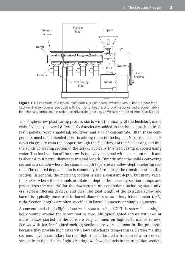
All single-screw extruders have several common characteristics. The main sections of the extruder include the barrel, a screw that fits inside the barrel, a motor drive system for rotating the screw, and a control system for the barrel heaters and motor speed. A schematic for an extruder is shown in Fig. 1.1. Many innovations on con-struction of these components have been developed by machine suppliers over the years. A hopper is attached to the barrel at the entrance end of the screw, and the resin is typically fed by gravity (flood fed) into the feed section of the screw. The resin is typically purchased in pellet form (most polyolefins for example), but pow-ders are common (PVDC resin). Recycle film from edge trim is often chopped and metered into the hopper. The extruder screw must first convey the pellets away from the feed opening, melt the resin, and then pump and pressurize it for a downstream filming process. This type of machine is referred to as a plasticating, single-screw extruder. The barrel is usually heated with a minimum of three temperature zones. These different temperature zones are consistent with the three functions of the screw: solids conveying, melting, and pumping or metering of the resin.
1.1 The Extrusion Process 3
Figure 1.1 Schematic of a typical plasticating, single-screw extruder with a smooth-bore feed section . The extruder is equipped with four barrel heating and cooling zones and a combination belt sheave gearbox speed reduction drivetrain (courtesy of William Kramer of American Kuhne)
The single-screw plasticating process starts with the mixing of the feedstock mate-rials. Typically, several different feedstocks are added to the hopper such as fresh resin pellets, recycle material, additives, and a color concentrate. Often these com-ponents need to be blended prior to adding them to the hopper. Next, the feedstock flows via gravity from the hopper through the feed throat of the feed casing and into the solids conveying section of the screw. Typically this feed casing is cooled using water. The feed section of the screw is typically designed with a constant depth and is about 4 to 8 barrel diameters in axial length. Directly after the solids conveying section is a section where the channel depth tapers to a shallow-depth metering sec-tion. The tapered depth section is commonly referred to as the transition or melting section. In general, the metering section is also a constant depth, but many varia-tions exist where the channels oscillate in depth. The metering section pumps and pressurizes the material for the downstream unit operations including static mix-ers, screen filtering devices, and dies. The total length of the extruder screw and barrel is typically measured in barrel diameters or as a length-to-diameter (L /D) ratio. Section lengths are often specified in barrel diameters or simply diameters.
A conventional single-flighted screw is shown in Fig. 1.2. This screw has a single helix wound around the screw root or core. Multiple-flighted screws with two or more helixes started on the core are very common on high-performance screws. Screws with barrier flighted melting sections are very common in film processes because they provide high rates with lower discharge temperatures. Barrier melting sections have a secondary barrier flight that is located a fraction of a turn down-stream from the primary flight, creating two flow channels in the transition section:

4 1 Extruder and Screw Design for Film Processing
a solids melting channel and a melt conveying channel. Barrier flighted sections will be discussed in more detail later. Many high-performance screws [1] have two or more flights in the metering section of the screw. The screw is rotated by the shank using either specially designed splines or by keys with rectangular cross sections. The mathematical zero position of the screw is set at the pocket where the screw helix starts. Most extruder manufacturers rotate the screw in a counterclockwise direction for viewers positioned on the shank and looking towards the tip. This rota-tion convention, however, is not standard.
Figure 1.2 Schematic of a typical single-flighted screw (courtesy of Jeff A . Myers of Robert Barr, Inc .)
The flight is a helical structure that is machined into the screw and extends from the flight tip to the screw core or root. The flight has a width at the flight tip called the flight land. The small clearance between the flight land and the barrel wall mini-mizes the flow of resin over the land. The polymer that does flow between the clear-ances supports the screw and centers it in the barrel. The radial distance between the flight tip and the screw root is referred to as the local flight height or channel depth. The feed section usually has the largest channel depth and provides the larg-est cross-sectional volume in the screw. The deep channel conveys the relatively low bulk density feedstock pellets into the machine via the motion of the helix. The feedstock is conveyed forward into the transition section or melting section of the screw. The transition section increases in root diameter in the downstream direc-tion, and thus the channel depth is decreasing. Here, the feedstock is subjected to higher pressures and temperatures, causing the feedstock to compact and melt. As the material compacts, its bulk density can increase by a factor of nearly two or more. As the feedstock compacts, the entrained air between the pellets is forced backwards and out through the hopper. For example, a pellet feedstock such as low density polyethylene (LDPE) resin can have a bulk density at ambient conditions of 0.58 g/cm3, while as a fully compacted solid bed in the transition section the density will approach 0.92 g/cm3 before melting starts. Thus for every unit volume of resin that enters the extruder, about 0.4 unit volumes of air must be expelled through the voids in the solid bed and then discharged through the hopper. The transition sec-tion is where most of the polymer is converted from a solid to a fluid. The fluid is then conveyed to the metering section where the molten resin is pumped to the

1.1 The Extrusion Process 5
discharge opening of the extruder. In general, the metering section of a conventional screw has a constant root diameter, and it has a much smaller channel depth than the feed section. The ratio of the channel depth in the feed section to the channel depth in the metering section is often referred to as the compression ratio of the screw.
The transition section shown in Fig. 1.2 is a conventional single-flighted design. These designs are still used for film operations, but barrier flighted melting sections are much more common. Barrier flighted melting sections will typically provide higher rates, lower discharge temperatures, a more stable discharge pressure, and extrudates that have fewer gels due to poor mixing. Barrier flighted melting sections are constructed by positioning a second flight (or barrier flight) in the transition sec-tion such that the solids are maintained on the trailing side and the molten resin on the pushing side. A schematic of a barrier flighted screw with an Egan (or spiral Maddock-style) mixer is shown by Fig. 1.3. A schematic of a cross section of a bar-rier melting section is shown in Fig. 1.4. The resin that is melted near the barrel wall is conveyed across the barrier flight and collected in the melt conveying chan-nel. The key design parameters include the position of the barrier flight, the depths of the channels, and the undercut clearance on the barrier flight. The undercut clearance is measured by positioning a segment of straight bar stock across the two main flights and then measuring the gap between the bar and the barrier flight land. For most designs, the barrier flight undercut is constant for the entire length of the section. As a very general rule, the undercut is typically about 0.01 times the diameter of the screw. Undercuts that are smaller than this rule, however, are often used. The position of the barrier flight sets the width of both channels. Many styles of barrier melting screws are commercially available, and many different variations of the channel widths and depths are used commercially.
Figure 1.3 Schematic of a Steward barrier flighted screw with a downstream dispersive (Egan) mixer (courtesy of William Kramer of American Kuhne)

6 1 Extruder and Screw Design for Film Processing
Figure 1.4 Cross-sectional view of a barrier melting section
Solid polymer fragments often exit the solids channel of barrier sections, or they can be discharged from conventional melting sections, especially at high rates and screw speeds. These solids need to be trapped and dispersed before the extrudate is shaped into film. Maddock-style mixers are typical dispersive mixers that are used for this application, but other mixers or high-performance sections are used. An Egan mixer (spiral Maddock-style mixer) is shown in Fig. 1.3 while other Maddock mixer styles are shown in Fig. 1.5.
Figure 1.5 Schematic for Maddock-style mixers . (a) A mixer with the flutes aligned in the axial direction; (b) a cross-sectional view perpendicular to the screw axis showing the clearance for the mixing flight; (c) a mixer with the flutes aligned in the axial direction; (d) an axial mixer with pressure relief zones at the entry and exits; (e) an Egan mixer with spiral flutes (courtesy of Jeff A . Myers of Robert Barr, Inc .)
Maddock-style mixers [2] are very commonly used due to their low cost to manufac-ture and their ability to disperse solid fragments, trap and melt polymer solids, and mitigate color and compositional gradients. Many styles are on the market under two basic types: (1) flutes parallel to the screw axis, and (2) flutes in a spiral pattern

1.1 The Extrusion Process 7
in the same direction as the flights. Schematics for these devices are shown by Fig. 1.5. For small-diameter screws, the mixer is generally constructed with four inflow flutes (or channels) and four outflow flutes. Larger diameter screws will have more paired flutes due to the larger available area at the screw circumference. For a Maddock mixer with the flutes parallel to the axis of the screw, molten polymer flows into the inflow flutes via a pressure gradient and then either continues to flow downstream in the flute or is passed through a small clearance between the mixing flight and the barrel wall. This small clearance is responsible for providing the dis-persive mixing characteristics of the device. Screw manufacturers typical specify the mixer flight height position relative to the main flight as an undercut. The under-cut u for a 63.5 mm diameter screw is typically about 0.5 to 1.2 mm, although for some applications and designs the clearance can be smaller. For this size screw with an undercut of 0.50 mm and a flight clearance of 0.07 mm, the clearance between the mixing flight and the barrel wall is 0.57 mm. The material that flowed across the mixing flight is accumulated in the outflow flute and is then flowed via pressure to the discharge end of the mixer. The wiper flight shown in Fig. 1.5 is set at the same height as the flight in the metering section. For mixers with the flutes in a spiral pattern, some of the forwarding flow in the flutes is due to the rotational movement of the flute relative to the barrel wall. Performance and simulation details can be found in the references [3, 4].
The specification of the undercut on the mixing flight for Maddock-style mixers is critical to its performance. As previously stated, all material must flow through the clearance provided by the sum of the undercut and flight clearance. If the clearance is too large, some medium- and small-size solid polymer fragments will not be trapped and melted by the device. If the clearance is too small, then a high-pressure gradient can occur, and there exists the possibility of increasing the temperature of the resin beyond its thermal capabilities, that is, causing degradation. The shear stress that the material experiences for flow across the mixing flight of the mixer can be estimated using Eqs. 1.1 and 1.2. The shear stress level is responsible for breaking up agglomerates and dispersing solid polymer fragments. A higher shear stress level will improve the ability of the mixer to disperse smaller size fragments. This shear stress calculation is based on screw rotation physics and is as follows:
(1.1)
(1.2)
where is the average shear rate for flow over the mixing flight in 1/s, u is the undercut clearance on the mixing flight, λ is the mechanical clearance of the flights, N is the screw rotation rate in revolutions/s, η is the shear viscosity at the tempera-ture of the mixing process and at shear rate , and τM is the shear stress that the
8 1 Extruder and Screw Design for Film Processing
material will experience for flow over the mixing flight. The stress level for flow across the mixing flight is typically between 50 and 200 kPa.
Several other design factors are important for the correct operation of Maddock-style mixers. These include the positioning of the mixer downstream from the melt-ing section, the distance between where the meter flight ends and the mixer starts, and the elimination of resin stagnation regions. The mixer must be positioned on the screw downstream far enough such that only low levels of solid polymer frag-ments exist. If the level of solids is too high in the stream, then the fragments may be melted and dispersed at a rate slower than the rate of the entering solids, causing the mixer to become plugged with solids and reducing the rate of the machine. As shown in Fig. 1.5, the mixer should be positioned about 0.3 to 0.5 diameters away from the end of the upstream metering section flight. This creates an annular gap where the material is allowed to flow evenly into all inflow flutes of the mixer. The annular gap is often undercut as shown by Fig. 1.5(d). If the flights extend close to the mixer entry, then it is possible that the inflow flute near the trailing side of the flight will not operate completely full of resin and thus may cause the resin to stag-nate and degrade. Moreover, flute depths should be streamlined and shallower at the entry end of the outflow flute and the exit end of the inflow flute. A common design error is to make these regions too deep, creating stagnation regions and causing resin degradation.
As an example of process design, linear low density polyethylene (LLDPE) resin is commonly used for blown film, cast film, and extrusion coating processes. Even though the resin grades are similar (melt indices or MIs do vary) for these three processes, the extrusion equipment is significantly different due to the require-ments of the die and downstream equipment. The blown film process requires an extrudate that is relatively low in temperature and typically in the range of 200 to 220°C. In order to plasticate and produce an extrudate in this temperature range the metering channel is relatively deep and the screw would be designed to rotate at speeds less than 100 rpm. For a 150 mm diameter screw with a square-pitch lead length (L = Db), the metering channel depth (H) would be between 9 and 12 mm. The cast film process requires an extrudate that is slightly higher in temperature and typically in the range of 240 to 260°C. The same 150 mm diameter screw would have a metering channel depth of 6 to 9 mm and the screw would rotate at higher speeds. The extrusion coating process requires an extrudate that is very high in temperature and often approaching 310°C. Here the metering channel depth would typically be about 3 to 4 mm for the 150 mm diameter screw, and the screw would be designed to rotate at very high speeds up to 230 rpm. These examples clearly show that the extrudate temperatures are set in part by the geometry of the meter-ing section channel, the conditions of the process, and the MI of the resin.
The specific rate is often a good measure of the relative discharge temperature for a process. The specific rate is simply the rate divided by screw speed. For the exam-

1.2 Rate Calculation 9
ples above, the specific rate for the metering channels would be the highest for the blown film screw with the deep metering channel and the lowest for the extrusion coating process screw with the very shallow channel. Thus as a general guideline, the extrudate temperature decreases when the specific rate of the screw increases at constant barrel diameter. The specific rates for the screws in these examples increased because the channel depth increased. The specific rate could also be changed by adjusting the lead length. The calculated specific rotation rate can be also used as a similar guideline for discharge temperature. This guideline, however, can be violated if the channel is extremely deep and a large positive pressure gradi-ent exists [1].
�� 1.2�Rate Calculation
For smooth-bore extruders, the rate of the extruder is controlled by the metering section of the screw. The expected rate for the process can be calculated based on the geometry of the metering channel, screw speed, pressure gradient, and the melt density and shear viscosity for the resin. The basic screw geometry for a single-flighted (p = 1) metering channel is shown in Fig. 1.6.
Figure 1.6 Geometric parameters for a single-flighted screw in the wound state
Two driving forces for flow exist in the metering section of the screw. The first flow is due just to the rotation of the screw and is referred to as the rotational flow com-ponent. The second component of flow is due to pressure gradients that exist in the z direction, and it is referred to as pressure flow. The sum of the two flows must be equal to the overall flow rate. The overall flow rate, Q, the rotational flow, Qd, and the pressure flow, Qp, for a constant depth metering channel are related as shown in Eq. 1.3. The subscript d is maintained in the nomenclature for historical consistency even though the term is for screw rotational flow rather than the historical drag flow concept. The method described here was developed by Rowell and Finlayson [5, 6] and later modified by Tadmor and Klein [7].

10 1 Extruder and Screw Design for Film Processing
(1.3)
The volumetric rotational flow term (Qd) depends on the several geometric para-meters and rotation speed. Since most extruder rates are measured in mass per unit time, the term Qmd is defined as the mass rotational flow:
(1.4)
(1.5)
where ρm is the melt density at the average fluid temperature of the resin, Vbz is the z component of the screw velocity at the flight tip, W is the average width of the channel, p is the number of flight starts, H is the depth of the channel, and Fd is the shape factor for plane couette flow. The analysis using plane couette flow does not take into account the effect of the flights (channel helix) on the flow rate. For an infinitely wide channel, no flights, Fd would be equal to 1. As the channel width approaches the height, Fd is about 0.5. It is important to include the shape factors when evaluating commercial screw channels. This becomes extremely important for deep channels where H/W does not approach zero. An additional correction factor can be used to improve the calculation of the rotational flow term [1]. The shape fac-tors are calculated as follows:
(1.6)
The velocity of the flight tip Vbz is calculated as follows:
(1.7)
thus (1.8)
where N is the screw rotation rate in revolutions per second, Db is the diameter of the inside barrel wall, L is the lead length, and θb is the helix angle at the barrel wall.
Because of the helical nature of the screw, the width of the channel is narrower at the core of the screw as compared to that at the barrel wall. The calculation of the rotational flow rate, however, requires the average width of the channel. The average width of the channel is calculated as follows:
(1.9)

1.2 Rate Calculation 11
(1.10)
thus (1.11)
(1.12)
where e is the width of the flight perpendicular to the edge, Dc is the diameter at the screw core, Wc is the channel width at the screw core, and θc is the helix angle at the screw core.
The volumetric pressure flow term, Qp, and the mass flow pressure flow term, Qmp, are computed as follows:
(1.13)
(1.14)
(1.15)
where Fp is the shape factor for pressure flow, is the pressure gradient in the channel in the z direction, and is the shear viscosity of the molten polymer at the average channel temperature and at an average shear rate, :
(1.16)
The shear rate in the channel contains contributions from the rotational motion of the screw and the pressure-driven flow. The calculation of the shear rate, , using Eq. 1.16, is based on the rotational component only and ignores the smaller contri-bution due to pressure flow.
The relationship between the pressure gradient in the z direction to the axial direc-tion, l, is as follows:
(1.17)
The pressure gradient is generally unknown, but the maximum that it can be for a single-stage extruder screw is simply the discharge pressure, Pdis, divided by the helical length of the metering section. This maximum gradient assumes that the pressure at the start of the metering section is zero. For a properly designed pro-

12 1 Extruder and Screw Design for Film Processing
cess, the actual gradient will be less than this maximum, and the pressure at the start of the metering section will not be zero.
(1.18)
where lm is the axial length of the metering section.
The total mass flow rate, Qm, is calculated by combining the flow components as pro-vided in Eq. 1.19 for the total mass flow rate. An additional correction factor can be used to improve the calculation of the rotational flow term [1].
(1.19)
Estimation of the rate and pressure gradient using Eq. 1.19 should be performed for each troubleshooting operation. Examples for its use are available elsewhere [1].
For grooved-bore extruders, the design of the feed section including the grooves and screw section control the rate of the process. This calculation of the rate is consider-ably more complex and is out of the scope of this chapter. Grooved bore extruders are discussed in detail elsewhere [8–10].
�� 1.3�Gels
A common contaminant in polyolefin film products is gels. The term gel is com-monly used to refer to any small defect that distorts a film product, creating an opti-cal distortion. There are many types of gels [11, 12], and the most common include (1) gels that are crosslinked via an oxidative process, (2) highly entangled resin gels (undispersed but not crosslinked), (3) unmelted resin, and (4) a different type of resin or contaminant such as wood, cloth fibers, or dirt. A crosslinked resin gel is typically formed during an oxidation process, resulting in the crosslinking of the resin chains and the generation of color bodies. These gels will not melt fully during analysis using a hot-stage microscope. Highly entangled gels are typically high molecular weight polymer chains that are highly entangled and thus difficult to dis-perse during the extrusion process. When analyzed using a hot-stage microscope, this gel type will melt as the stage temperature is increased. When the stage tem-perature is then decreased, the gel will crystallize before the surrounding material, creating the appearance of a gel. Since these gels are not oxidized they are not asso-ciated with color. They are commonly referred to as undispersed or unmixed gels. Unmelted resin exiting with the discharge can sometimes occur, especially at high extrusion rates. These gels will melt during heating with a hot-stage microscope,

1.3 Gels 13
and typically they will not re-form during the cooling phase. Numerous sophisti-cated methods are available for analyzing gels, including epi-fluorescence micros-copy, polarized light microscopy, and electron microscopy with X-ray analysis.
Gels can be generated from many different sources and include (1) the resin manu-facturer, (2) the converting process, (3) pellet blending of resins with significantly different shear viscosities, (4) pellet blending of different resin types, and (5) direct contamination. Modern resin manufacturing processes exclude oxygen from the system and are very streamlined such that process areas with long residence times do not exist. As such crosslinked and oxidative gels are likely not generated by the manufacturer. Improperly designed extrusion equipment and processes, however, are common, leading to the oxidative degradation of resins and crosslinked gels. Several case studies in the next sections show how poorly designed processing equipment can lead to crosslinked and unmixed gel contamination of products.
Established protocols for gel analysis in polymer films are well documented in the literature [11–14]. Typically a film with defects is visually inspected using a low power dissecting microscope. The gels can be classified based on size, color, and shape and isolated using a razor blade or scissors. Cross sections of the gels ranging from 5 µm to 10 µm thick are collected at temperatures below the glass transition (Tg) temperature of the film using a cryogenic microtome, about –80°C to –120°C. For optical examination, a thin section containing the gels is placed on a glass microscope slide with a drop of silicone oil and covered with a glass cover slip. Addi-tional sections are collected for examination via hot-stage microscopy and for com-positional identification if needed.
After collecting the sections, the remaining polished block-face containing the remainder of the gel is retained. In many instances, gels arise from inorganic con-taminants such as the metals from pellet handling equipment, extruders, or compo-nents from masterbatches. Examination of these inorganic components are best per-formed with the block-face sample using a scanning electron microscope (SEM) equipped with an energy dispersive X-ray detector (EDX) [15, 16]. In some cases, additives or inorganic residues are present in low concentrations within the gels. A method to enrich the concentration of these materials is to expose the block-face containing the gel to oxygen plasma. Etching will preferentially remove the polymer at a much faster rate than the inorganic materials, enriching these components for elemental analyses. It must be noted that prior to SEM and EDX analyses, a thin conductive coating like carbon is typically evaporated onto the sample to render it conductive under the electron beam.
The most common type of gel is caused by oxidative processes that crosslink the PE chains. The best way to identify this gel type is by observation with polarized light and ultraviolet (UV) light sources. Transmitted polarized light microscopy repre-sents an effective technique [17] that can be used to investigate structures in crys-

14 1 Extruder and Screw Design for Film Processing
talline films. For example, black speck gels were contaminating a multilayer film product. The gels were relatively brittle when cut for analysis. The source was unknown. The detail of the gel is clearly visible using transmitted polarized light, as shown in Fig. 1.7(a). Close examination of this gel using epi-fluorescence with an ultraviolet light source caused an intense fluorescence emission, as shown in Fig. 1.7(b). This type of emission suggests thermal oxidation and crosslinking of the polymer. Microinfrared analysis of the gel indicated that it contained oxidized PE and maleic anhydride [1, 12]. This material likely formed on the metal surfaces of the extruder and then flaked off during a minor process instability. The material then flowed downstream and contaminated the film as a gel.
Figure 1.7 Transmitted polarized light images of a thermally oxidized and crosslinked gel in a multilayer film: (a) photograph in polarized light, and (b) the gel fluorescing under UV light [12] . Photographs were provided by E . Garcia-Meitin of The Dow Chemical Company
Crosslinked gels are oxidized gels, but the level of oxidation is not enough to cause them to fluoresce under UV light. The gels may have a level of crystallinity and thus be birefringent under polarized light. For example, the slightly birefringent gel shown in Fig. 1.8(a) was studied using a temperature-programmable, hot-stage, polarizing light microscope [16]. The optical melting temperature (Tm) of the gel was measured at 128°C and consistent with the PE used to make the product, as shown in Fig. 1.8(b). To determine if the gel was unmixed (highly entangled but not crosslinked), the gel was held above the melting temperature (135°C) and then stressed. A dental tool was used to stress the top of the glass slip cover. Crosslinked gels will appear birefringent, as shown in Fig. 1.8(c), in response to the anisotropy of stress distribution in the gel to polarized light. The gel dimensions and shape remained after cooling, verifying crosslinking, as shown in Fig. 1.8(d). If the gel was highly entangled and not crosslinked (unmixed gel), the gel would have disappeared after stress and cooling were applied.

1.3 Gels 15
Figure 1.8 Hot-stage microscopy of a crosslinked gel in a crystalline monolayer film: (a) below the melting temperature, (b) optical melting point at 128°C, (c) appearance of birefringence after stressing at 135°C, and (d) intact crosslinked gel after cooling to 30°C [12] . Photographs were provided by E . Garcia-Meitin of The Dow Chemical Company
The origin of defects causing discoloration in polyolefin pellets can be identified using light and electron microscopy. For example, PE pellets from an in-plant re cycle repelletizing process contained pellets that were off-color and had black specks, as shown in Fig. 1.9(a). One of these defects was isolated using the cross-sectioning technique, as shown in Fig. 1.9(b). The cross section revealed an intense reddish particle that caused the discoloration of the pellet. SEM and EDX microanalyses were used to determine that the defects contained primarily iron and oxygen, and it likely was iron oxide. A backscatter electron image (BEI) of the pellet block-face sample showed the defect causing the discoloration, and the elemental spectrum was shown to be iron oxide [1]. Metal-based defects can originate from process equipment, railcars used for shipment, pellet transfer lines, and poor housekeeping. The origin of the iron oxide was likely from a storage bin.

16 1 Extruder and Screw Design for Film Processing
Figure 1.9 Photographs of foreign contamination in pellets of a repelletized reclaim stream: (a) photomicrograph of discolored PE pellets containing dark defects, and (b) transmitted polarized light micrograph of a pellet cross section containing a defect [12] . Photographs were provided by E . Garcia-Meitin of The Dow Chemical Company
In another example, a multilayer film product was experiencing occasional gels. The gels were isolated and the cross sections were collected as shown in Fig. 1.10(a). These gels contained highly birefringent particles that resided in the core layer. The outer film layers appeared amorphous, and the core layer was slightly birefringent. The optical melting temperature of the core layer was determined to be 123°C while the birefringent gels melted at 265°C. The melting temperature of 123°C was con-sistent with the polyethylene (PE) resin used to produce the core layer. The higher melting temperature of the material and microinfrared analyses of the defects indi-cate that they were foreign contaminants, and they were identified as a polyester resin. The polyester resin was used in another process in the converting plant, and it inadvertently contaminated the PE feedstock.
Figure 1.10 Photographs of gels in the core layer of a three-layer film: (a) transmitted polarized light, and (b) hot-stage microscopy was used to determine the melting temperatures of the core resin and defects [12] . Photographs were provided by E . Garcia-Meitin of The Dow Chemical Company

1.4 Troubleshooting Extrusion Processes 17
Another common contaminant that produces gels is fiber, as shown in Fig. 1.11. In many cases, these contaminants are cotton fibers from clothing and gloves or cellu-losic fibers from packaging materials. Fourier transform infrared (FTIR) spectros-copy is one of the best techniques for determining the chemical functionality of organic-based defects in PE films.
Figure 1.11�Transmitted bright-field image of a PE film containing a fibrous gel [12]
Once the contaminant is identified, the troubleshooter must determine how the material entered the feedstock stream. Process controls must be identified and implemented to mitigate the contaminant source.
�� 1.4�Troubleshooting Extrusion Processes
Eventually every single-screw extrusion process will experience periods when the machine is operating at a performance level that is less than designed. During these periods, the cost of manufacturing will increase due to the production of off-specifi-cation products, loss of production rates, high levels of recycle, higher labor costs, and lower daily production of prime product. In extreme cases, the problem can be so severe that the line must be shut down. Obviously the plant needs to restore the operation of the line to the original performance level as soon as possible to maxi-mize profitability. Many things can cause an extruder to malfunction, including mechanical and electrical failures, installation of new equipment, process changes, and resin changes. A complete process for troubleshooting an extrusion process can be obtained in reference 1. Several of the most common problems associated with film production processes are presented in this section.

18 1 Extruder and Screw Design for Film Processing
1.4.1�Improper Shutdown of Processing Equipment
Shutting down an extrusion line occurs for many reasons, including planned shut-downs for maintenance, shift changes, changing filtering screens, product changes, and many unplanned events. A shutdown period is defined here as a period when the screw is not rotating and thus resin is not discharging from the line. If the shut-down period is relatively short such that very little resin degradation can occur, then the extruder barrel temperatures can be maintained at the operating set point temperatures. If the length of the shutdown is long relative to the time required to create a significant level of degradation products, then the extruder should be either purged with a more thermally stable resin or the barrel set point temperatures should be decreased to considerably lower temperatures. Purging the resin with an inert gas to exclude oxygen is also effective at mitigating gels [1]. An extruder that is maintained at process conditions long enough to create degradation products can be very difficult to bring back online running prime product. In this case, the sur-faces of the screw and all metal surfaces in contact with molten resin may become coated with degradation products, as shown in Fig. 1.12. The time to purge them out can be extremely long and very expensive. For example, LLDPE resins can form crosslinked gels and black specks after 30 minutes of being off-line at process tem-peratures. If the shutdown is under 30 minutes, the barrel can be held at the pro-cess temperature. If the shutdown is longer but the line will be brought back online soon, the screw could be rotated at a low speed of 5 rpm to keep resin flowing, miti-gating the formation of degradation products. For longer shutdown periods, the extruder should be purged using an LDPE resin and then cooled to ambient tem-perature.
Figure 1.12 Photograph of a screw that had numerous shutdowns where the extruder was maintained at operating temperatures for an extended time . The extruder was purged prior to removing the screw, yet dark degraded resin covers most areas of the screw [1]
Antioxidant chemicals are typically added at levels that stabilize the resin during normal melt processing. They are not meant to protect the resin from degradation during an extended shutdown period. Antioxidants are slowly consumed during the extrusion process, and thus they can be fully consumed during an extended shut-

1.4 Troubleshooting Extrusion Processes 19
down period. When they are fully consumed, the resin system is not protected from degradation, and thus degradation reactions will occur at accelerated rates.
1.4.2�Gel Showers in a Cast Film Process
Crosslinked gels can form in stagnant regions of screw channels, transfer lines, and dies. The time required for these gels to form range from about 30 minutes for linear low density polyethylene (LLDPE) resin up to 12 days for low density polyethylene (LDPE) resin. Stagnant regions can occur at entries and exits of mixers [1] and bar-rier sections, and they can occur when the metering channel of smooth-bore extrud-ers is not controlling the rate. In these cases, a section upstream of the metering section is rate limiting, causing portions of the metering section to operate partially filled [18, 19]. When these channels operate partially filled, the main flow is on the pushing side of the channel while the trailing side operates void at first. After a period of time, clean resin gets into the void regions and rotates with the screw for long durations. Eventually the resin will degrade, forming crosslinked gels. Slight process upsets can dislodge this material, allowing the material to flow downstream, creating a gel shower in the film.
A film plant was extruding an LDPE resin into a specialty product using a cast film process [18, 19]. Due to high demand, a new 88.9 mm diameter, 33 L / D extruder was installed in the plant. Soon after start-up the product was acceptable and high quality. After 12 days, the line began to experience intermittent discharges of crosslinked material (gel showers) and carbon specks. Photographs of these gels are shown in Fig. 1.13. In some cases, the gel showers were observed two to three times per day and would last from 1 to 5 minutes. The gels were clearly crosslinked and were brown in color. The extrudate temperature was higher than expected for the process. The intermittent gels resulted in production downtime due to purging and in numerous customer complaints. A high and costly level of quality control was required to remove the gel-contaminated product from the prime product. Due to the high amount of downtime and the high levels of quality control needed, the opera-tion of the new line was considerably more expensive than planned.
Figure 1.13 Photographs of crosslinked gels in an LDPE film
20 1 Extruder and Screw Design for Film Processing
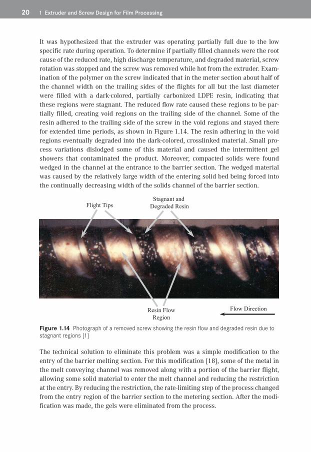
It was hypothesized that the extruder was operating partially full due to the low specific rate during operation. To determine if partially filled channels were the root cause of the reduced rate, high discharge temperature, and degraded material, screw rotation was stopped and the screw was removed while hot from the extruder. Exam-ination of the polymer on the screw indicated that in the meter section about half of the channel width on the trailing sides of the flights for all but the last diameter were filled with a dark-colored, partially carbonized LDPE resin, indicating that these regions were stagnant. The reduced flow rate caused these regions to be par-tially filled, creating void regions on the trailing side of the channel. Some of the resin adhered to the trailing side of the screw in the void regions and stayed there for extended time periods, as shown in Figure 1.14. The resin adhering in the void regions eventually degraded into the dark-colored, crosslinked material. Small pro-cess variations dislodged some of this material and caused the intermittent gel showers that contaminated the product. Moreover, compacted solids were found wedged in the channel at the entrance to the barrier section. The wedged material was caused by the relatively large width of the entering solid bed being forced into the continually decreasing width of the solids channel of the barrier section.
Figure 1.14 Photograph of a removed screw showing the resin flow and degraded resin due to stagnant regions [1]
The technical solution to eliminate this problem was a simple modification to the entry of the barrier melting section. For this modification [18], some of the metal in the melt conveying channel was removed along with a portion of the barrier flight, allowing some solid material to enter the melt channel and reducing the restriction at the entry. By reducing the restriction, the rate-limiting step of the process changed from the entry region of the barrier section to the metering section. After the modi-fication was made, the gels were eliminated from the process.

AAdams 265Agassant 102, 122, 134, 149, 165, 166, 167, 168, 169, 170,
171, 172, 175, 176, 177, 180, 181, 182, 184, 185, 186Aird 134Alamo 42Alfrey Jr . 76, 85, 87, 120Alothman 43Amon 87, 88André 122, 184Anturkar 134, 172, 180Arda 149Armstrong 75Asai 351Asano 308Ast 54Athene 32Avenas 165, 180Avila-Orta 265
BBabel 31, 33, 47, 62, 63Baird 286Balzano 351Bar 13Barone 350Barq 134, 167, 168, 172Beaulne 122, 129Becker 79Benkhoucha 102Bertrand 126Billon 134Blackson 13, 14Blid 286Blyler 166Bogue 121Bosse 286Bouamra 168Bourgeois 129Bourgin 167, 168, 172Bourrigaud 168, 169, 180Boyce 265Braatz 184
Bradley 85, 87Brancewitz 32, 34, 39, 42, 43Bras 31, 45Breil 211, 223Briston 195Brown 350Buckley 53, 265Bullwinkel 32, 34, 39, 42, 43, 44Bunn 280Burger 265Butler 12, 13, 32, 113, 128, 129
CCain 122, 184Cakmak 32, 265, 278, 316Campbell 4, 9, 10, 12, 13, 14, 15, 16, 17, 18, 19, 20, 21,
22, 23, 31, 32, 33, 34, 39, 42, 43, 44, 47, 48, 50, 51, 52, 54, 55, 62, 63, 113, 114, 117, 120, 124, 232, 233, 235, 237, 250, 258, 259, 275, 278, 286, 290, 291, 316
Cao 33, 43, 44, 47, 48, 50, 51, 52, 54, 62, 63, 124Carla 265Carley 77, 78Carneiro 113, 114, 117, 118Carradini 350Carreau 32, 42, 169, 170Carrier 178Castillo 113, 114, 117, 118Chae 317Chambon 181Champchesnel 265Chang 165, 166, 265Chen 351Cheng 350Chisholm 76Choi 31Chu 42, 265Chuang 317Clark 267, 272, 279Cleereman 76Coates 87, 88, 92, 94, 96, 99Coccorullo 350Cogswell 350Colombo 103Combeaud 149
Author Index

372 Author Index
Cook 79Corradini 350, 361Cotto 134Coyle 103, 117Crochet 134Cudby 350Culberson 32, 39Culter 73
DDabas 168, 169, 180Darus 13, 14David 286Dealy 350Debbaut 134Dees 31de Jeu 351Demay 122, 134, 165, 166, 167, 169, 170, 171, 175, 176,
177, 178, 180, 181, 182, 184, 185, 186Denn 122, 141, 144, 165, 166, 180, 182, 184, 350DeRosa 350De Witte 96, 97, 98, 99d’Halewyn 134Ding 32, 42Dobroth 134Doi 134, 136Dooley 22, 23, 77, 79, 84Doufas 122, 184Drda 350Drechsel 166Du 351Duffo 134Dupret 42Dupuy 168, 169, 180
EEichnorn 265El Kissi 350Elmoumni 351Ente 166Erwin 134Ewing 126
FFahy 102Fava 279Finlayson 9Fischer 182, 350, 351Fisher 141, 144Fortin 178Fu 351Funaki 134, 141, 142, 143, 351, 355, 360, 364, 366Funatsu 134, 144, 146
GGalante 42Galay 32Gammell 74Gao 126Garcia-Meitin 12, 13, 14, 15, 16, 17Garner 280Geil 350, 351Gezovich 350Ghaneh-Fard 32, 42, 169, 170Ghanta 350Ghiljels 166Gieniewski 166Giesekus 144Gilbert 350Gilmour 102Gletin 350Goldman 286Gomez 350Goodrum 79Gough 87, 88Govaert 351Graves 32Greco 317Grubb 350Guerra 13, 350Gupta 117, 166
HHan 31, 85, 87, 123, 184, 317, 351Harashina 265Hassan 265Hatzikiriakos 165, 174, 350Haudin 122, 134, 167, 168, 172, 184Hayashi 286, 316, 317Headley 85, 88Hearle 265Hemsley 13Hendra 350Henrichsen 122, 184Hernandez 73Hoffman 350Horn 265Hoshino 31, 32Housiadas 126, 184Housmans 351Hristova 351Hsiao 265, 350Hsu 351Hu 351Huang 34, 48, 51, 62, 102Hyun 19, 20, 21, 22, 23, 165, 166, 167, 171, 174, 181, 183,
184, 187

Author Index 373
IIeki 265, 278Ihim 265Ikeda 281Imai 350Imamura 265, 278Inn 350Isaki 134, 136Ishihara 141, 165, 182Ito 134, 136, 272Iwai 290Iwamoto 316, 317, 350Iyenger 134
JJabarin 194Jaffe 265Jarecki 183Jenkins 84Jo 317Johnson 42Jones 265Jons 85, 88Jung 165, 166, 167, 174, 181, 183, 184, 187
KKaji 350, 351Kajiwara 134, 144, 146Kamal 42, 122Kamatani 288, 355Kanai 33, 47, 54, 62, 63, 113, 114, 117, 120, 129, 134, 136,
137, 141, 142, 143, 145, 146, 147, 148, 149, 150, 151, 158, 169, 184, 232, 233, 235, 237, 238, 247, 249, 250, 256, 258, 260, 275, 278, 286, 287, 288, 290, 291, 292, 296, 302, 304, 305, 308, 311, 316, 317, 350, 351, 355, 360, 364, 366
Kanaya 350, 351Kang 265, 316Kanho 286Karlbauer 7Kase 134, 136, 141, 165, 182, 275, 316Katan 195Katoh 350Katsumoto 144, 146Kawai 272Kawakami 265Keller 31, 46Kenner 265Keskkula 317Khan 265Kikutani 265, 272Kim 181, 183, 184, 265, 317Kimura 308
Kitajima 147, 148, 149, 150, 350Klein 7, 9Knittel 128Kodjie 12, 13, 14, 15, 16, 17Koerber 220Kohler 166, 183Kohno 158Kometani 145, 146, 147, 148, 149, 150, 350Kondo 360Konishi 350, 351Kopytko 85, 86, 87, 88, 94, 96, 99, 100, 101Kouba 102Kral 102Krexa 32, 34, 39, 42, 43Kuramoto 256Kuratani 355, 366Kurtz 129, 130, 350Kwack 31Kyu 32, 38, 42
LLaffargue 169, 170, 171, 184, 185, 186Lafleur 32, 42, 126, 169, 170Langowski 220Lauritzen 350Lavallee 96, 98Lee 75, 166, 167, 181, 183, 184, 187Lengalova 86, 87, 88Lenz 32Li 126, 351Lindstrom 286Liu 121, 351Llana 265Lorentz 265Lund 220Luo 122Lusing 286
MMaack 85, 87Machin 31Mack 286Mackley 149, 350Maddock 6, 22Malincoico 317Mandelkern 42Mandell 350Manley 265Marchal 134Marin 168, 169, 180Martins 265Martyn 87, 88, 92, 94, 96, 99Matovich 182Matsuba 350

374 Author Index
Matsumoto 265, 278Matsumura 145, 146, 147, 148, 149, 150, 350Matsuo 182, 265Matsuzawa 287, 288, 355Mavridis 85, 87, 91, 102, 103McHugh 122, 166, 183, 184McMahon 48Meijer 351Men 351Menges 54Merten 149Mezghani 350Miayji 351Michaeli 113Migler 165, 174Miki 232, 233, 235, 237, 316Miller 350, 361Minoshima 169Mitsoulis 122, 129Miyaji 351Mizukami 350Moffat 22Monasse 122, 184Monnerie 265Moore 258Mori 350Morihara 286Münstedt 149Muslet 122
NNa 351Nagarajan 55, 58, 61, 62, 63Nagasawa 31, 32Nakamura 286Nakao 272Nash 286Natta 350, 361Naumovitz 84Nishi 317Nishida 350, 351Nitta 351Nobrega 113, 114, 117, 118Nomura 350Nonomura 250, 275, 316Norton 46Nye 31, 45
OObot 124O’Brien 117Oda 267, 272Ogawa 351Ogita 265
Ohlsson 181Ohta 260Okui 272Oliver 76, 77, 78, 79Ooki 265Oura 317
PPantani 350Parent 169, 170Park 123, 184Paul 317Pearson 120, 129, 182, 184Peiti 168Perdikoulias 85, 87, 88, 102, 104, 105, 106, 113, 114, 117Peters 126, 351Petraccone 350Petrie 54, 120, 129, 180, 184Piau 350Pirkle 184Plucktaveesak 350Polich 286Polychronopoulos 113, 114, 117, 118Potente 12Predohl 54Procter 102
RRahalkar 350Raley 79Ramamurthy 350Ramanathan 85, 88Ran 265Rasmussen 32, 34, 39, 42, 43Rastogi 351Rauwendaal 102Ree 32, 38, 42, 286Rehg 85, 88Reuschle 13Rhee 316Rhodes 32, 38Robert 149Robinson 286Roozemond 351Roth 167, 168, 172Rowell 9Ruese 350Ruppel 126Rutgers 350Ryan 31, 32, 45

Author Index 375
SSaha 85, 86, 87, 88, 89, 90, 91, 92, 93, 94, 95, 96, 98,
99, 100, 101, 104, 105, 106, 117Saillard 102Saito 364Sakai 146Sakaki 134, 144Sakamoto 250Sakauchi 286, 287, 288, 291, 292, 296, 302, 304, 316,
355Sarafrazi 122Saul 118Savargaonkar 13Scheirs 13Schoenberg 286Schöppner 12Schrauwen 351Schrenk 76, 85, 87, 88, 103Schuetz 286Sebastian 102Selke 73Sergent 165Sergot 265Serhatkulu 32Shah 182Shanker 85, 88Sharif 122Shen 351Shetty 85, 87Shibayama 317, 350Shimizu 272Shin 166, 167, 181, 183, 184Shroff 85, 87, 91Sics 265Sidriopoulos 54, 123, 124, 125, 126, 129Silagy 134, 168, 169, 174, 175, 176, 177, 180, 181Simon 118Skaki 134Slichter 350Smith 134Socrate 265Sollogoub 134Song 183, 184, 286, 316Spalding 4, 9, 10, 12, 13, 14, 15, 16, 17, 18, 19, 20, 21, 22,
23Spares 87, 88, 94Spirgatis 126Spoelstra 351Spruiell 31, 32, 41, 42, 121, 279Srinivas 350Stanford 31, 45Steenbakkers 351Stein 32, 38, 42, 265, 272, 350Stewart 350Stolle 134
Suga 145, 146, 147, 148, 149, 150, 350Sun 117Supaphol 32, 41Swartjes 351Sweeney 33, 48, 50, 51, 52, 54Swenson 79
TTabar 32, 38Tadmor 7, 9Takahashi 350Takarada 272Takashige 286, 290, 291, 305, 308, 311, 316, 317Takayanagi 351Takeda 317Takenobu 31, 32Takeo 134, 136Takeuchi 232, 233, 235, 237, 316Takino 260Takubo 351Tamura 256, 260Tanaka 158, 350Tanifuji 113, 114, 117, 118Tanner 120, 122Tant 32, 39Tas 31Tassin 265Teutsch 83Thiel 7Thomas 286Tian 123, 129Titomanlio 350Tobita 232, 233, 235, 237, 316Tonelli 350Toussaint 350Toyoda 258, 316Tsamopoulos 184Tsou 350Tsuboshima 286Tsunashima 258, 316Tzoganakis 85, 87, 88, 89, 90, 91, 93, 94, 95, 96, 99,
104, 105, 106, 117
UUehara 286, 287, 288, 291, 292, 296, 302, 304, 316,
355Uenoyama 317Unsal 265Upmeier 80
Vvan Aarsten 38van Breemen 351

376 Author Index
van der Beek 351Veazy 128, 129Vega 351Vergnes 149, 165Verhoyen 42Vickers 31Ville 350Vincent 165Viny 265Vlachopoulos 54, 113, 114, 117, 118, 124, 125, 126Vlcek 85, 86, 87, 88, 89, 90, 91, 93, 94, 95, 96, 99,
100, 101, 102, 113, 114, 117
WWagner 113, 223Wakabayashi 158Walter 286Wang 317, 350, 351White 31, 54, 57, 166, 169, 184, 267, 272, 286, 316Wilkes 31William 286Willis 350Winter 265, 351Wyxkoff 350
XXiao 72, 74, 75, 77, 79, 84Xu 122Xue 87, 88
YYagi 134, 136Yamada 250, 260, 275, 286, 287, 288, 291, 292, 296,
302, 304, 305, 308, 316, 355, 364, 366Yamaguchi 94Yamamoto 94Yamane 166Yan 351Yasumoto 94Yeow 134, 172, 184Yoon 350Yoshida 238Yoshii 258, 316Yu 31Yuon 184
ZZatloukal 85, 86, 87, 88, 89, 90, 91, 92, 93, 94, 95, 96,
97, 98, 99, 100, 101, 104, 105, 106, 117Zhang 126, 351Zhao 351Zheng 351Zhou 351Ziabicki 183, 272Zippenfeld 54Zitzenbacher 7
Symbolα crystal 261β crystal 261
Aabsolute black body radiation 53additives 158air knife 202air rings 124aluminum bubble 56analyzer 43annular die 30, 33antioxidant chemicals 18antistatic additive 158apparent emissivity 53apparent reflectivity 53average intensity 40Avrami kinetics 41, 42axial position 40axisymmetric instabilities 183
Bbalance equation 288barrier flighted screw 5beta-gauge system 220biaxially oriented film 232, 238biaxially oriented tentering film 231, 234biaxial stretching 194birefringence 266, 271, 275black body 52 – emissivity 53 – temperature 49
bleeding 158 – speed 159
blocking 156blown film 73, 112, 119, 165blow-up ratio (BUR) 112, 169, 184BOPA 226BOPE 227BOPET 194, 226BOPLA 227BOPP 194, 196, 225, 238, 260BOPS 227
boundary layer 58, 59, 61bowing 250 – phenomena 250, 275
Bragg’s law 279branched polyethylene blends 42bubble 112 – collapsing 127 – deformation 292 – forming 119 – instabilities 32 – velocity 34
bulk deformation 39bulk temperature 51BUR 112
Ccapacitor 215, 226carbon specks 22Carreau-Yasuda equation 116cast film 73, 164CCD camera 43chain-track system 205chill roll 201clips 205CO2 footprint 227Coanda effect 124coat hanger 78COC 228coefficient of static fiction 151coextrusion 114, 198 – visualization 92
coherent light 32, 33composition distribution 244conservation law 52contact winding 209cooling 123 – air 34 – air flow 54 – phenomena 181 – process 239 – rate 45 – system 241
crater-like surface 260critical Deborah number 181
Subject Index
378 Subject Index
critical draw ratio 167, 179cross equation 116crystalline morphology 31crystallization 42, 47 – kinetics 32
cylinder plate 339
DDDR 112Deborah number 167, 180deformation 34 – behavior 137 – histories 34 – rate 34
detect spherulites 360die bolt adjustment 200die design 117die flow 111 – analysis 113
diffusion coefficients 158direct drives 202direct numerical simulation 173dog bone defect 175double bubble 195double bubble tubular film 285–287, 291, 296, 301,
302, 304, 305, 307, 308, 311 – machine 287 – process 232, 319
down-gauging 228drawdown ratio (DDR) 112drawing instability 164draw ratio 165, 169, 175, 184draw resonance 141 – instability 165, 171
Eease-of-tearing properties 333easy-tear film 328edge trim 209edge views 279eigenvalue 173, 179, 184electrostatic 203 – pinning 236
Elmendorf tearing test (ASTM D1922) machine 333elongation viscosity 180emissivity 48–50end view 280entangled gels 12equi-biaxial stretching 270equipment producers 72EVOH 286Ewald sphere 278extrusion 198
Ffiber spinning 164, 182filament breakage 167film 50 – blowing 111, 169, 183 – breakage 143 – casting 134, 135, 136, 146 – cooling 46 – drawing machine 265 – extrusion 70 – properties 62, 295 – structures 72 – tentering machine 275 – thickness 47, 48, 50 – velocity 43
filtration 199flat-panel displays 226flat-screen displays 216flight radii 22flow analysis 102flux measurements 61four-lobed pattern 37freeze-frost line 29freeze line 31, 47freeze line height (FLH) 123frozen-in strain 50
GGammell 75gels 12gel showers 19generalized Newtonian fluid model (GNF) 115Giesekus model 144GNF 115growth 41
Hhaze 151, 157HDPE 157heat flux 56, 57 – meters 55
heat loss 47heat recovery systems 207heat seal temperature 151, 155, 156heat setting 280 – zones 275
heat transfer 30, 201 – coefficient (U) 36, 46, 53, 54, 60, 137
He-Ne laser 43Henky strains 35higher-order structure 264

Subject Index 379
IIBC 113, 126impact strength 153, 320, 332impingement 46improper shutdown of processing equipment 18infrared detector 51infrared (IR) absorption 220infrared temperature 30in-line coater 223inorganic contaminants 13in situ observation 253, 254instability 141, 241integrated process control (IPC) 217interfacial instabilities 85interfacial shear stress 87internal bubble cooling (IBC) 31, 113, 126interplanar spacing 279intrinsic birefringence 281IR surface temperature 33isotropic 215
KKuhn statistical theory 273
Llaboratory extruder 223laboratory tenter stretched film 296lab stretcher 223lamellae 31laminar flow 57LCD 228LDPE 146light scattered 32linear motor 212linear stability analysis 173, 182LISIM 252 – technology 211
Lithium-ion batteries 228LLDPE 152, 153, 156, 157, 302local temperature 50longitudinal stretching 241Lorentz-Lorenz equation 281
MMaddock-style mixers 6mass flow 34 – rate 35
material design 301MD and TD properties 62MDO 203melt fracture 147, 150Melt Index (MI) 301
melt pumps 199melt temperature 45membrane approximation 183membrane model 175membranes 228microscopy 32Moffat eddies 22molecular orientation angle (MOA) 220monoaxial stretching 195motorized table 33multigap stretching 204multilayer 198, 224multimanifold die 77MXD6 307, 308, 329, 340
Nneck-in 175, 181necking 144, 146, 243, 244nip speed 34nonaxisymmetric instability 169, 183noncontact system 48noncontact temperature 33normalized plastic strain 63nozzle boxes 207nucleation 41
Ooff-center positions 275OLED 228online SALS 32OPET 237OPP 236OPS 237, 291optical 215 – anisotropy 265, 276 – axis 275 – film 226 – retardation 265
organic electronics 216, 226orientation 31oscillations 32oxidative gels 13
PPA 232PA6 286, 305, 308, 329, 339partially oriented yarn 272PC 228PE 286periodic fluctuations 167periodic instabilities 166periodic oscillations 41PET 236, 258, 259, 286

380 Subject Index
phase change 54phase shift 266physical crosslinks 31, 63physical properties 151, 152, 157, 257pilot line 222pinning 202planar elongation 269planar orientation 274, 281plastic strain 31PMMA 228polarizability 281polarized fluorescence technique 327polarized light 32polyamide 232polyethylene (PE) 136, 302polyethylene terephthalate (PET) 232, 264polymer chains 31polymer processing aids 96polypropylene (PP) 136, 146, 159, 232, 238, 304polystyrene 232power law equation 116POY 272PP 154, 159, 238, 244, 259, 260, 286PPS 286predicted temperature 36preferential orientation 281preheating 203 – process 287 – zone 275
pressure flow 11pull roll stand 208puncture resistance 226PVDC 286
Qquality data management system (QDM) 221quick quenching 358quiescent cooling 39
Rradial fibrils 31radiation 47 – spectrum 48
radius 34raman spectroscopy 32reciprocal lattice vector 279reciprocal space 279reflectivity 49refraction 32refractive index ellipsoid 274refractive indices 268relaxation 214, 267 – time 63, 246
representative SALS images 37
resin degradation 18rheological models 62roll data history module (RDH) 221roller chains 205RTD 48rubber elasticity theory 273
SSALS 30, 32 – equipment 33 – images 40 – patterns 37
saturation solubility 159SAXS 32scale-up rule 308scattering intensity 43, 45screen 43screw rotational flow 9secondary crystallization 42second invariant 115second (scalar) invariant 115self-ordering 282semicrystalline polymer 31, 47separator film 228sequential biaxial stretching 233, 273, 311, 319sequential stretching 232shark skin 147, 149shrinkability 299shrinkage 214, 296 – stress 291
sigmoidal curve 41simultaneous biaxial stretching 311, 319simultaneous stretching 211, 232single-flighted screw 4single manifold die 76single-screw extruders 2sliding chain track systems 206slip agents 158slippage 156small-angle light scattering device (SALS) 30,
338solar back sheets 226solubility 158spatial intensity 38spherulites 42, 44spherulitic 31spherulitic crystalline structure 30spider die 79spiral 113 – die 114, 117
spiral mandrel die 80spontaneous structural ordering 272stability curve 186stackable die 84Stanton number 174, 182

Subject Index 381
steady state 34straight line cut 334, 335strain 34strain energy potential function 273strain-hardening 268strain rate 34, 35, 63stress 50, 271stress-optical coefficient 272stress-optical rule 268, 272stress-strain curve 323stress-strain pattern 324stress-strain relationship 214stress versus birefringence behavior 272stretching force 168stretching patterns 214stretching process 241, 287stretching stress 329stretching temperature 203structure development 253structure-processing property 69substitution 228superstructure 152surface roughness 147, 149, 260surface temperature 43, 51surface tracking method 177
TTAC 228tacticity 244take-up ratio (TUR) 112tandem extruder 234T-die casting 135–137, 143, 152, 242TDO 205tearing resistance 333technology center 222TEM 338temperature 43, 47, 48, 50, 52 – plateau 36, 37, 47
TEM photographs 337tension control 209tentering process 232, 319tentering zone 275theoretical analysis 135, 287theoretical equations 141thermal isolation 83thermal-transfer film 226thermistor 48thermocouple 48thermosetting 205thickness 43 – control 218 – uniformity 305, 340
thinning 61thin polymer films 29thin shell approximation 121
three-dimensional analyses 268through view 279tilting 275time elapsed 36time to crystallization 34TNSD sign stability criterion 87transient heat transfer 56transmission electron microscope (TEM) 336,
366transmissivity 49transparency 157, 365TREF (temperature rising elution fractionation) 155,
156, 301, 302troubleshooting extrusion processes 17true stress 267tubular blown film 29tubular film 113, 119, 135, 308tubular process 319TUR 112turbulence 54twin-screw extruder 199, 234two-dimensional heat transfer model 54two-stage mechanism 44
UUDY 272unattainable drawing region 180unattainable region 182unattainable zone 169undrawn yarn 272uniaxial stretching 267, 268unit cell 280unmixed gels 21uptime 218UV stabilizers 158
Vvelocity 34 – measurements 61
Venturi effect 124viscoelastic behavior 180viscoelasticity 122viscoelastic model 144viscoelastic-plastic 62visco-plastic 62visualization 253volume-filling spherulites 39
Wwave type of interfacial instabilities 87WAXD 278WAXS 32web inspection 221

382 Subject Index
weight percent HDPE 43Weissenberg number 122wide-angle X-ray diffraction (WAXD) 278 – patterns 326
winder 209worn screw 23
XX-ray radiation 220
Zzigzag interfacial instabilities 96