Fill Station Design and Tank Sizing - Ray Murray · 2016-10-03 · Fill Station Design and Tank...
6
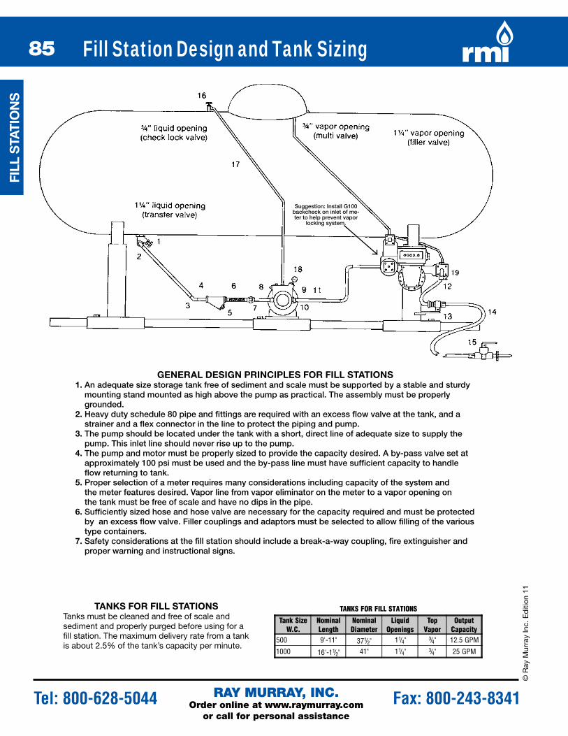
85 © Ray Murray Inc. Edition 11 RAY MURRAY, INC. Order online at www.raymurray.com or call for personal assistance Tel: 800-628-5044 Fax: 800-243-8341 Fill Station Design and Tank Sizing TANKS FOR FILL STATIONS Tanks must be cleaned and free of scale and sediment and properly purged before using for a fill station. The maximum delivery rate from a tank is about 2.5% of the tank’s capacity per minute. GENERAL DESIGN PRINCIPLES FOR FILL STATIONS 1. An adequate size storage tank free of sediment and scale must be supported by a stable and sturdy mounting stand mounted as high above the pump as practical. The assembly must be properly grounded. 2. Heavy duty schedule 80 pipe and fittings are required with an excess flow valve at the tank, and a strainer and a flex connector in the line to protect the piping and pump. 3. The pump should be located under the tank with a short, direct line of adequate size to supply the pump. This inlet line should never rise up to the pump. 4. The pump and motor must be properly sized to provide the capacity desired. A by-pass valve set at approximately 100 psi must be used and the by-pass line must have sufficient capacity to handle flow returning to tank. 5. Proper selection of a meter requires many considerations including capacity of the system and the meter features desired. Vapor line from vapor eliminator on the meter to a vapor opening on the tank must be free of scale and have no dips in the pipe. 6. Sufficiently sized hose and hose valve are necessary for the capacity required and must be protected by an excess flow valve. Filler couplings and adaptors must be selected to allow filling of the various type containers. 7. Safety considerations at the fill station should include a break-a-way coupling, fire extinguisher and proper warning and instructional signs. Suggestion: Install G100 backcheck on inlet of me- ter to help prevent vapor locking system. TANKS FOR FILL STATIONS Tank Size W.C. Nominal Length Nominal Diameter Liquid Openings Top Vapor Output Capacity 500 9'-11" 37 1 / 2 " 1 1 / 4 " 3 / 4 " 12.5 GPM 1000 16'-1 1 / 2 " 41" 1 1 / 4 " 3 / 4 " 25 GPM FILL STATIONS
-
Upload
truongkien -
Category
Documents
-
view
221 -
download
0
Transcript of Fill Station Design and Tank Sizing - Ray Murray · 2016-10-03 · Fill Station Design and Tank...
85
pU
mp
S, m
ETE
RS
pU
mp
S, m
ETE
RS
© R
ay M
urra
y In
c. E
diti
on 1
1
RAY MURRAY, INC.Order online at www.raymurray.com
or call for personal assistance
Tel: 800-628-5044 Fax: 800-243-8341
Fill Station Design and Tank Sizing
TAnKS FOR FiLL STATiOnSTanks must be cleaned and free of scale and sediment and properly purged before using for a fill station. The maximum delivery rate from a tank is about 2.5% of the tank’s capacity per minute.
GEnERAL dESiGn pRincipLES FOR FiLL STATiOnS1. An adequate size storage tank free of sediment and scale must be supported by a stable and sturdy
mounting stand mounted as high above the pump as practical. The assembly must be properly grounded.
2. Heavy duty schedule 80 pipe and fittings are required with an excess flow valve at the tank, and a strainer and a flex connector in the line to protect the piping and pump.
3. The pump should be located under the tank with a short, direct line of adequate size to supply the pump. This inlet line should never rise up to the pump.
4. The pump and motor must be properly sized to provide the capacity desired. A by-pass valve set at approximately 100 psi must be used and the by-pass line must have sufficient capacity to handle flow returning to tank.
5. Proper selection of a meter requires many considerations including capacity of the system and the meter features desired. Vapor line from vapor eliminator on the meter to a vapor opening on the tank must be free of scale and have no dips in the pipe.
6. Sufficiently sized hose and hose valve are necessary for the capacity required and must be protected by an excess flow valve. Filler couplings and adaptors must be selected to allow filling of the various type containers.
7. Safety considerations at the fill station should include a break-a-way coupling, fire extinguisher and proper warning and instructional signs.
Suggestion: Install G100 backcheck on inlet of me-ter to help prevent vapor
locking system.
TANKS FOR FILL STATIONS
Tank SizeW.C.
NominalLength
NominalDiameter
LiquidOpenings
TopVapor
OutputCapacity
500 9'-11" 371/2" 11/4" 3/4" 12.5 GPM
1000 16'-11/2" 41" 11/4" 3/4" 25 GPM
FiLL
STA
TiO
nS

86
pU
mp
S, m
ETE
RS
pU
mp
S, m
ETE
RS
© R
ay Murray Inc. E
dition 11
RAY MURRAY, INC.Order online at www.raymurray.com
or call for personal assistance
Tel: 800-628-5044 Fax: 800-243-8341
Fill Station Valve KitsKiTS FOR pORTABLE cYLindER And SmALL mOTOR FUEL FiLLinG REQUiREmEnTSdESiGnEd TO BE USEd wiTh BLAcKmER LGF1-1 hp 10 Gpm pUmp And SmiTh dwiZm-3 And EGiZm-3
nOTE: For the addition of either the Liquid Control or Neptune 3⁄4" meter the following items must be ordered separately—
3⁄4" union, elbows for alignment between pump and meter, 1⁄2" tubing (K or L) for vapor eliminator line and coupling to connect line to multivalve on top of tank.
KiTS FOR LARGER mOTOR FUEL FiLLinG REQUiREmEnTSdESiGnEd FOR USE wiTh BLAcKmER LGF1p-1.5 hp 15 Gpm pUmp And SmiTh dwhZm-5 And EchZm-5
PF-11 FITTING AND PIPE NIPPLE KIT**Includes the following:
Key* RMI Part No. Description2 104-16 1" - 90° Elbow2 125-02 1" X 2" Nipple3 103-16 1" 45° Elbow4 125-03 1" X 3" Nipple7 109-16 1" Union8 125-09 1" X 9" Nipple8 150-2016 1-¼" X 1" Concentric Swage9 106-1612 1" X ¾" Hex Bushing11 124-03 ¾" X 3" Nipple11 107-1208 ¾" X ½" Reducer Coupling17 (2) 48IK 5/8" X ¾ " Flare Fittings17 KCT12-10 Copper Tubing-Type K, 10 ft.17 (2) NS4I 5/8" Flare Nuts
PK-11 COMPLETE VALVING KIT
Key* RMI Part No. Description1 C407M-10-03 Tank Valve w/ Relief5 ME652S Strainer6 FLEX 1-12 Flex Connector10 ME880-6/22 Excess Flow Valve14 FH-1218 ½" Hose w/ ends 18 ft.15 ME791C Hose End Valve15 ME390 POL Filler Coupling15 901H Adaptor15 ME392 Adaptor16 ME449 Transfer Valve16 ME880-6/14 Excess Flow Valve16 MEH225 Relief Valve18 ME202 Snubber18 GB-400 Pressure Gauge
PK-11B VALVE KIT W/ BREAK A WAYSame as PK-11 Valve Kit, plus:
Key* RMI Part No. Description13 ME860S-6 Break-A-Way Coupling* See diagram on preceeding page.
PF-11B FITTING KIT USED W/BREAK-A-WAY
Key* RMI Part No. Description12 LPGH-3/4-3C ¾" X 3 ft. Hose w/ Ends13 106-1208 ¾" X ½" Hex Bushing19 108-12 ¾" Tee19 106-1204 ¾" X ¼" Hex Bushing19 125-06 1" X 6" Nipple19 TSS3169 Vent Valve
PK-153 COMPLETE VALVING KIT
Key* RMI Part No. Description1 C407M-10-03 Tank Valve w/ Relief5 ME652S Strainer6 FLEX 1-12 Flex Connector10 ME880-6/22 Excess Flow Valve14 LPGH-3/4-15C ¾" Hose w/ ends 15 ft.15 ME820-6 Hose End Valve15 ME635-6 1-¾" Acme Coupling15 ME210 Adaptor15 ME390 Adaptor15 G-820 Adaptor16 ME449 Transfer Valve16 ME880-6/14 Excess Flow Valve16 MEH225 Relief Valve18 ME202 Snubber18 GB-400 Pressure Gauge19 10AXXX Liquid Level Gauge
PF-15B FITTING KIT USED W/ BREAK AWAYSame as PF-15 Fitting Kit, plus:
Key* RMI Part No. Description12 LPGH-3/4-3C ¾" X 3 ft. Hose w/ Ends19 124-03 ¾" X 3" Nipple19 106-1204 ¾" X ¼" Hex Bushing19 108-12 ¾" Tee19 125-06 1" X 6" Nipple19 TSS3169 Vent Valve
PK-153B VALVE KIT W/ BREAK A WAYSame as PK-153 Valve Kit, plus:
Key* RMI Part No. Description13 ME860S-6 Break-A-Way Coupling* See diagram on preceeding page.
PF-15 FITTING & PIPE NIPPLE KIT**
Key* RMI Part No. Description2 104-16 1" - 90° Elbow2 125-02 1" X 2" Nipple4 (2) 125-03 1" X 3" Nipple7 109-16 1" Union8 125-09 1" X 9" Nipple8 150-2016 1-¼" X 1" Concentric Swage9 106-1612 1" X ¾" Hex Bushing11 150-1612 1" X ¾" Concentric Swage17 (2) 48IK 5/8" X ¾ " Flare Fittings17 KCT12-10 Copper Tubing-Type K, 10 ft.17 (2) NS4I 5/8" Flare Nuts
FiLL STATiO
nS

87
pU
mp
S, m
ETE
RS
pU
mp
S, m
ETE
RS
© R
ay M
urra
y In
c. E
diti
on 1
1
RAY MURRAY, INC.Order online at www.raymurray.com
or call for personal assistance
Tel: 800-628-5044 Fax: 800-243-8341
Fill Station Valve KitsBLAcKmER FiLL STATiOn
dESiGnEd FOR USE wiTh d-2 cABinET
PK-D2 FITTING PACKAGE*RMI Part No. Description
C407M-10-03 Tank Valve w/ ReliefME652S Strainer105-12 ¾" Hex PlugFLEX 1-12 Flex ConnectorME202 SnubberGB-400 Pressure GaugeME870-6 ¾" Back CheckME880-6/22 Excess Flow ValveMEN401-06 ¾" Angle ValveMEH225 ¼" External Relief ValveMEJ602H ¼" Elbow w/ Relief & BleedME449 Transfer ValveME880-6/14 Excess Flow ValveME791CJ Toggle w/bleederFH-1218 ½" Hose w/½" x ¾" ends 18 ft.LPGH-3/4-3C ¾" X 3 ft. Hose w/ EndsME860S-6 ¾" Break-A-Way CouplingBL-4-4LP ¼"F X ¼"M Street ElbowA680 MPOL X 3/8"" Fl AdaptorG-820 POL Filler CouplingME393 1 5/16" ACME AdapterME569 1 ¾" ACME Fill Adapter
PF-D2 FITTING PACKAGE
RMIPart No.
Description Quantity
104-16 1" 90o Elbow 3109-16 1" Union 2
150-1612 1" x 3/4" Concentric Swage 1124-00 3/4" Close Nipple 2104-12 3/4" 90° Elbow 148IK 5/8" x 1/2" Flare Adapter 2NS4I 5/8" Flare Nut 2KCT12-20 1/2" Copper Tubing-Type K 20 ft.NS4E 3/8" Flare Nut 2LCT14-20 1/4" Copper Tubing-Type L 20 ft.
125-05 1" X 5" Nipple 2150-2016 1-¼" X 1" Concentric Swage 1125-06 1" X 6" Nipple 1
d-2 cABinET
BLACKMER FILL STATIONDesigned for Use w/ D-2 Cabinet
Key* RMI Part No. Description PK-D2 PF-D2
1 LGF1P-1.5HP Pump and Motor ~ ~ 2 125-05 1" X 5" Nipple ~ X 3 104-16 1" 90° Elbow ~ X 4 125-06 1" X 6" Nipple ~ X 5 109-16 1" Union ~ X 6 150-1612 1" X ¾" Concentric Swage ~ X 7 ME870-6 ¾" Back Check X ~ 8 400051-001 Neptune Meter ~ ~ 9 MEN401-06 ¾" Angle Valve X ~ 10 MEJ602H ¼" Elbow w/ Relief & Bleed X ~ 11 124-00 ¾" Close Nipple ~ X 12 ME880-6/22 Excess Flow Valve X ~ 13 104-12 ¾" 90° Elbow ~ X 14 FH-1218 ½" Hose w/ ½" X ¾" ends 18 ft. X ~ 15 LPGH-3/4-3C ¾" X 3 ft. Hose w/ Ends X ~ 16 ME860S-6 ¾" Break-A-Way Coupling X ~ 17 ME791CJ Toggle w/bleeder X ~ 18 G-820 POL Filler Coupling X ~ 19 C407M-10-03 Tank Valve w/ Relief X ~ 20 150-2016 1-¼" X 1" Concentric Swage ~ X 21 ME652S Strainer X ~ 22 FLEX 1-12 Flex Connector X ~ 23 ME449 Transfer Valve X ~ 24 MEH225 ¼" External Relief Valve X ~ 25 ME880-6/14 Excess Flow Valve X ~ 26 BL-4-4LP ¼"F X ¼"M Street Elbow X ~ 27 ME202 Snubber X ~ 28 GB400 Pressure Gauge X ~ n/s 1124 Scale ~ ~ All items listed above come in assembled cabinet, scale needs to be ordered separately
FiLL STATiOnThis package is available
assembled with a steel or aluminum cabinet. contact Rmi customer
Service for details.
FiLL
STA
TiO
nS

88
pU
mp
S, m
ETE
RS
pU
mp
S, m
ETE
RS
© R
ay Murray Inc. E
dition 11
RAY MURRAY, INC.Order online at www.raymurray.com
or call for personal assistance
Tel: 800-628-5044 Fax: 800-243-8341
Fill Station Valve Kits
11/4" BLAcKmER pAcKAGE
11/4" cORKEn pAcKAGE
Pump Bypass
11/4" Pump Suction
Pump Bypass
11/4" Pump Suction
PKV-125 VALVE KIT
Key* RMI Part No. Description3 C407M-10-3 Angle Valve plus Hydrostatic5 ME653S Strainer plus Plug6 FLEX-1-1/4-14 Flex Connector
9GB-400, NMF20BK,GS20S
Pressure Gauge plus Valveplus Snubber
10 A8013D Excess Flow Valve17 LPGH-3/4-15C Hose with Ends18 ME820-6 Snap Valve19 ME210 Snap Valve19 ME390 Snap Valve19 G-820 Snap Valve19 ME635-6 Fill Connector20 ME880-6/14 Excess Flow Valve
21 ME449, MEH225Service Valve plusHydrostatic
*See diagram above.
PKF-125 FITTINGS KIT
Key* RMI Part No. Description2 126-03 11/4" x 3" Nipple4 104-20 (2) 11/4" 90o Elbow7 109-20 (2) 11/4" Union8 126-06 (2) 11/4" x 6" Union11 108-12 3/4" Tee12 124-08 3/4" Nipple13 124-03 3/4" Nipple
22KCT12, 48IK (2),NS4I (2)
Copper Tubing forBy-Pass
*See diagram above.
PKB-125 BREAK-A-WAY
Key* RMI Part No. Description
14 MEN401-06MEJ602H
3/4" Angle Valve plusBleeder plus Hydrostatic
15 LPGH-3/4-3C Hose w/ Ends16 ME860S-6 Break-A-Way Coupling
*See diagram above.
PKV-C1012 VALVE KIT
Key* RMI Part No. Description3 C407M-10-3 Angle Valve plus Hydrostatic5 ME653S Strainer plus Plug6 FLEX-1-1/4-14 Flex Connector
9GB-400, NMF20BK,GS20S
Pressure Gauge plus Valveplus Snubber
12 ME880-6/22 Excess Flow Valve16 LPGH-1/2-15C Hose with Ends17 ME791CJ Snap Valve18 ME390 Fill Connector19 ME880-6/14 Excess Flow Valve
20 ME449, MEH225Service Valve plusHydrostatic
*See diagram above.
PKF-C1012 FITTING KIT**
Key* RMI Part No. Description2 126-03 11/4" x 3" Nipple4 104-20 (2) 11/4" 90o Elbow7 109-20 11/4" Union8 126-06 11/4" x 6" Nipple10 150-1612 1" x 3/4" Swage Nipple11 108-12 3/4" Tee
21KCT12, 48IK (2),NS4I (2)
Copper Tubingfor By-Pass
*See diagram above.
PKB-C1012 BREAK-A-WAY
Key* RMI Part No. Description
13 MEN401-06MEJ602H
3/4" Angle Valve plusBleeder plusHydrostatic
14 LPGH-3/4-3C Hose w/ Ends
15 ME860S-6106-1208
Break-A-Way Coupling,3/4" x 1/2" Bushing
*See diagram above. **For c12 order 151-2420 Swage
FiLL STATiO
nS
89
pU
mp
S, m
ETE
RS
pU
mp
S, m
ETE
RS
© R
ay M
urra
y In
c. E
diti
on 1
1
RAY MURRAY, INC.Order online at www.raymurray.com
or call for personal assistance
Tel: 800-628-5044 Fax: 800-243-8341
Cabinets - Fill Station and Exchange
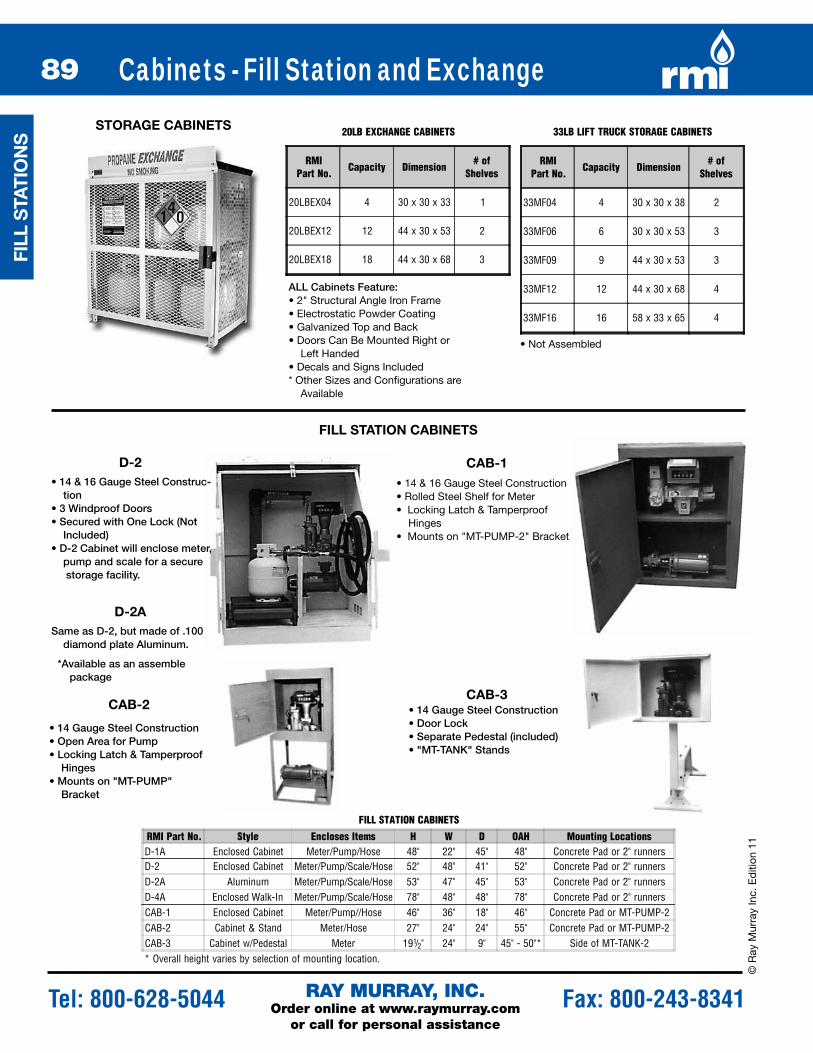
ALL Cabinets Feature:• 2" Structural Angle Iron Frame• Electrostatic Powder Coating• Galvanized Top and Back• Doors Can Be Mounted Right or
Left Handed• Decals and Signs Included* Other Sizes and Configurations are
Available
• 14 & 16 Gauge Steel Construc-tion
• 3 Windproof Doors• Secured with One Lock (Not
Included)• D-2 Cabinet will enclose meter,
pump and scale for a secure storage facility.
• 14 & 16 Gauge Steel Construction• Rolled Steel Shelf for Meter• Locking Latch & Tamperproof
Hinges• Mounts on "MT-PUMP-2" Bracket
FiLL STATiOn cABinETS
d-2 cAB-1
• 14 Gauge Steel Construction• Open Area for Pump • Locking Latch & Tamperproof
Hinges• Mounts on "MT-PUMP"
Bracket
• 14 Gauge Steel Construction• Door Lock• Separate Pedestal (included)• "MT-TANK" Stands
cAB-3cAB-2
STORAGE cABinETS 20LB EXCHANGE CABINETS
RMIPart No. Capacity Dimension
# ofShelves
20LBEX04 4 30 x 30 x 33 1
20LBEX12 12 44 x 30 x 53 2
20LBEX18 18 44 x 30 x 68 3
33LB LIFT TRUCK STORAGE CABINETS
RMIPart No. Capacity Dimension
# ofShelves
33MF04 4 30 x 30 x 38 2
33MF06 6 30 x 30 x 53 3
33MF09 9 44 x 30 x 53 3
33MF12 12 44 x 30 x 68 4
33MF16 16 58 x 33 x 65 4
FILL STATION CABINETS
RMI Part No. Style Encloses Items H W D OAH Mounting Locations
D-2 Enclosed Cabinet Meter/Pump/Scale/Hose 52" 48" 41" 52" Concrete Pad or 2" runnersD-1A Enclosed Cabinet Meter/Pump/Hose 48" 22" 45" 48" Concrete Pad or 2" runners
D-2A Aluminum Meter/Pump/Scale/Hose 53" 47" 45" 53" Concrete Pad or 2" runners
CAB-1 Enclosed Cabinet Meter/Pump//Hose 46" 36" 18" 46" Concrete Pad or MT-PUMP-2CAB-2 Cabinet & Stand Meter/Hose 27" 24" 24" 55" Concrete Pad or MT-PUMP-2CAB-3 Cabinet w/Pedestal Meter 191/2" 24" 9" 45" - 50"* Side of MT-TANK-2* Overall height varies by selection of mounting location.
D-4A Enclosed Walk-In Meter/Pump/Scale/Hose 78" 48" 48" 78" Concrete Pad or 2" runners
Same as D-2, but made of .100 diamond plate Aluminum.
d-2A
*Available as an assemble package
• Not Assembled
FiLL
STA
TiO
nS

90
pU
mp
S, m
ETE
RS
pU
mp
S, m
ETE
RS
© R
ay Murray Inc. E
dition 11
RAY MURRAY, INC.Order online at www.raymurray.com
or call for personal assistance
Tel: 800-628-5044 Fax: 800-243-8341
Fill Station Equipment and Accessories
1124
• Model 1124• Rugged, Durable Design• Cast Iron Base & Platform• Platform is 173/4" x 231/2"• Bronze Beam Assembly w/
Etched Numbers for Easy to Read Measurements
• 1000# Capacity: S Model for 20# Cylinder L Model for 100# Cylinder
• Fill Mobile & Stationary Tanks
• Lightweight & Well Balanced
• Will Not Disconnect From Filler Valve While Lever in Open Position
• Fine Filter Incorporated in Nozzle
• Long Swivel Nut for Fork Lift Truck Filling
FAiRBAnKS pORTABLE ScALES GASGUARd Lp nOZZLE
The “User Friendly” Dispensing Nozzle
Used on cylinder filling manifold. Shuts off gas supply when specified cylinder weight is reached. Operates on propane vapor or air. No electricity required.1/2" FNPT inlet and outlet. For beam scales only.
N201
AUTOmATic cYLindER FiLLinG VALVE
TAnK mOUnTinG STAndS And SKidS
Our heavy duty stand includes 18" bracket feet for additional stability. The entire mount slides onto 2" pipe (not included).
A B C
Automatically Fills:Opd Valves
Forklift cylinderpOL cylinder Valves
• Filling is initiated simultaneously with connec-tion to the valve.
• Insignificant loss of product.• Air-release and gas flow. Stoppage in one quick
motion• Fits easily into any tank collar.• Balanced jig for easy suspension.
cAVAnGA AUTO FiLLinG GUn
HORIZONTAL TANK STANDS
RMI Part No. Description ItemMT-TANK-2 Heavy Duty Stand 18" tall x 40" wide A & CMT-PUMP-2 Heavy Duty Pump Bracket BMT-TANK-3**Special order only.
Reinforced Stand for 1450, 1850, 1990 Gal. Tank A & C
RMI Part No. DescriptionN201 Filling ValveN201RK Repair Kit for N201
N201HA Hose Assembly Only
HORIZONTAL TANK STANDS
RMI PartNo.
Inlet PneumaticConnection
Item
129A003 3/8" FNPT 1/4" FNPT-AirFemale POL,
Standard Valve
129A006 3/8" FNPT 1/4" FNPT-Air1 1/4" ACME Forklift
Adaptor129A009 3/8" FNPT 1/4" FNPT-Air OPD Type I ACME
BA-8-4HP1/4" Male FNPT x 1/2" female NPT -
Hose to Valve Adaptor
RMI Part No. Style Height1124 Standard Pillar 43"1124-S Short Pillar - 20# 28"1124-L Tall Pillar - 100# 66"1124-100 100# Counterweight (1 lb)1124-200 200# Counterweight (2 lb)1124-400 400# Counterweight (4 lb)
RMI PartNo. Description
LG.20S 3/4" FNPT x 13/4" ACME
FiLL STATiO
nS