Fill level switch Product series WSx - SKF.com · Fill level switch Product series WSx For oil and...
12
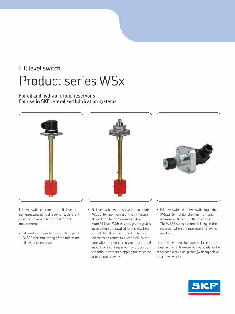
Fill level switch Product series WSx For oil and hydraulic fluid reservoirs For use in SKF centralized lubrication systems Fill level switches monitor the fill level in non-pressurized fluid reservoirs. Different designs are available to suit different requirements. • Fill level switch with one switching point (WS32) for monitoring of the minimum fill level in a reservoir. • Fill level switch with two switching points (WS35) for monitoring of the minimum fill level and for early warning of mini- mum fill level. With this design, a signal is given before a critical oil level is reached so that the oil can be topped up before the machine comes to a standstill. At the time when the signal is given, there is still enough oil in the reservoir for production to continue without stopping the machine or interrupting work. • Fill level switch with two switching points (WS33) to monitor the minimum and maximum fill levels in the reservoir. The WS33 stops automatic filling of the reservoir when the maximum fill level is reached. Other fill level switches are available on re- quest, e.g. with three switching points, or for other media such as grease (with capacitive proximity switch).
Transcript of Fill level switch Product series WSx - SKF.com · Fill level switch Product series WSx For oil and...
Fill level switch
Product series WSxFor oil and hydraulic fluid reservoirs For use in SKF centralized lubrication systems
Fill level switches monitor the fill level in
non-pressurized fluid reservoirs. Different
designs are available to suit different
requirements.
• Fill level switch with one switching point
(WS32) for monitoring of the minimum
fill level in a reservoir.
• Fill level switch with two switching points
(WS35) for monitoring of the minimum
fill level and for early warning of mini-
mum fill level. With this design, a signal is
given before a critical oil level is reached
so that the oil can be topped up before
the machine comes to a standstill. At the
time when the signal is given, there is still
enough oil in the reservoir for production
to continue without stopping the machine
or interrupting work.
• Fill level switch with two switching points
(WS33) to monitor the minimum and
maximum fill levels in the reservoir.
The WS33 stops automatic filling of the
reservoir when the maximum fill level is
reached.
Other fill level switches are available on re-
quest, e.g. with three switching points, or for
other media such as grease (with capacitive
proximity switch).
PUB LS/P2 12593 EN · 1-1702-EN
Fill level switch
Note for the use of fill level switches
!Be mindful of oil viscosity
SKF float switches may only
be used in mineral and synthetic oils
up to a maximum effective viscosity of
1 500 mm²/s. Use in media with an
effective viscosity > 1 500 mm²/s can
cause an increase in the shear forces
between the float and contact tube,
leading to failure of the float switch.
This can result in insufficient lubrication
and thereby to machine damage.
0,40,800
0,2
50
100
0,4 0,6
100
1,00
0 0,2
50
200
150
230 230
200
150
1,00,6 0,8
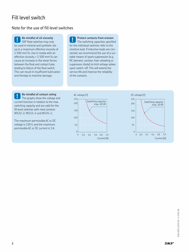
!Be mindful of contact rating
The graphs show the voltage and
current function in relation to the max.
switching capacity and are valid for the
fill level switches with reed contacts
WS32-2, WS33-2 und WS35-2.
The maximum permissible AC or DC
voltage is 230 V, and the maximum
permissible AC or DC current is 1 A.
Current [A]
AC voltage [V]
Current [A]
DC voltage [V]
Switching capacity max. 60 VA
Switching capacity max. 40 W
!Protect contacts from erosion
The switching capacities specified
for the individual switches refer to the
resistive load. If inductive loads are con-
nected, we recommend the use of a sui-
table means of spark suppression (e.g.
RC element, varistor, free-wheeling or
suppressor diode) to limit voltage spikes
upon switch-off. This will extend the
service life and improve the reliability
of the contacts.
2

PUB LS/P2 12593 EN · 1-1702-EN
Fill level switch
Product overview
WS63-2
WS68
WS32-2WS32-S10 WS32-S30 WS32-2-V57-A
Productselection table
Series
Switching points
Function / contact type
Plug connector
Voltage, current, switching capacity
Fitting position
Page
WS32-S10 1 min. fill level / 1 changeover Circular connector with LED DIN EN 175201-804
24 V DC / 1 A; 24 W 1) Vertical 4–5, 6
WS33-S10 2 max. fill level / 1 changeover min. fill level / 1 changeover
Circular connector with LED DIN EN 175201-804
24 V DC / 1 A; 40 W 1) Vertical 4–5, 6
WS35-S10 2 early warning / 1 changeover min. fill level / 1 changeover
Circular connector with LED DIN EN 175201-804
24 V DC / 1 A; 40 W 1) Vertical 4–5, 6
WS32-S30 1 min. fill level / 1 changeover Circular connector M12×1 with LED
24 V DC / 1 A; 30 W Vertical 4–5, 7
WS33-S30 2 max. fill level / 1 NC contact min. fill level / 1 NC contact
Circular connector M12×1 with LED
24 V DC / 1 A; 30 W Vertical 4–5, 7
WS35-S30 2 early warning / 1 NO contact min. fill level / 1 NC contact
Circular connector M12×1 with LED
24 V DC / 1 A; 30 W Vertical 4–5, 7
WS32-2 1 min. fill level / 1 changeover Square connector DIN EN 175301-803-A
See graph on page 2 Vertical 4–5, 8
WS33-2 2 max. fill level / 1 NO contact min. fill level / 1 NC contact
Square connector DIN EN 175301-803-A
See graph on page 2 Vertical 4–5, 8
WS35-2 2 early warning / 1 NO contact min. fill level / 1 NC contact
Square connector DIN EN 175301-803-A
See graph on page 2 Vertical 4–5, 8
WS32-2-V57-A 1 min. fill level / 1 changeover Circular connector M12×1 24 V AC / 1 A; 24 VA 1) 48 V DC / 1 A 40 W 1)
Vertical 4–5, 9
WS33-2-V57-A 2 max. fill level / 1 NO contact min. fill level / 1 NC contact
Circular connector M12×1 24 V AC / 1 A; 24 VA 1) 48 V DC / 1 A 40 W 1)
Vertical 4–5, 9
WS35-2-V57-A 2 early warning / 1 NO contact min. fill level / 1 NC contact
Circular connector M12×1 24 V AC / 1 A; 24 VA 1) 48 V DC / 1 A 40 W 1)
Vertical 4–5, 9
WS63-2 1 min. fill level / 1 NO or NC contact (depending on mounting pos.)
Plug connector DIN EN 175301-803-A
240 V AC / 0,5 A; 100 VA200 V DC / 0.5 A; 50 W
Horizontal 10–11
WS68 1 min. fill level / 1 NC contact Plug connector DIN EN 175301-803-A
48 V AC / DC0.25 A; 10 VA / 10 W
Horizontal 10–11
1) Safety measures to be applied for correct operation: “Protective extra-low voltage” (PELV) Standards: EN 60204-1 / IEC 60204-1; HD 60364-4-41 / DIN VDE 0100-410 / IEC 60364-4-41
3

PUB LS/P2 12593 EN · 1-1702-EN
Fill level switch for vertical installation
Designs
Contact tube with float
Square connector with cable socket (2)
!Note!
This illustration shows possible
different designs of the WS32, WS33
and WS35. The product customizer on
the following page allows functional
assembly of a complete fill level switch
including plug connector, immersion
depth, and switching points.
Circular connector with LED and cable socket (S10)
Circular connector M12x1 with LED (S30)
Switching points Circular connector M12x1 (2-V57-A)
Technical data WS32 / WS33 / WS35
Technical data
Switching element . . . . . . . . . . . . . Reed contactProtection class according to DIN EN 60529 . . . . . . . . . . . . . . . .
IP 65
Operating/ media temperature . . . . –10 to + 80 °CMedia . . . . . . . . . . . . . . . . . . . . . . . Mineral and synthetic oils
with an effective viscosity of max. 1 500 mm2/s
Fitting position . . . . . . . . . . . . . . . . Vertical
Materials: Flange . . . . . . . . . . . . . . . . . . . . . . AluminumContact tube . . . . . . . . . . . . . . . . . . CuZnSeals . . . . . . . . . . . . . . . . . . . . . . . NBRFloat . . . . . . . . . . . . . . . . . . . . . . . . PP
M4
45°
ø42
ø54
Drilling template for assembly
4

PUB LS/P2 12593 EN · 1-1702-EN
Order code W S – +
Product series
Fill level switch for vertical installation
Product customizer
Order example
WS35-S10+B37• Fill level switch for mini-
mum level with early warning
• Circular plug with LED and cable socket (DIN EN 175201-804)
• Length 300 mm
Switching points and ordered lengths
Switching points Minimum Minimum and maximum fill levels Early warning andfill level min. fill level
Code 32 1) 33 1) 35 1)
Switching point – 50 65 100 150 –max. fill level(dimension A: see drawing p. 6)
Ord
ered
lengt
h L
[mm
]
100 C49 – – – – –110 C25 – – – – –120 C17 V69 W51 – – C17130 B27 Y72 W80 – – B27140 B97 X16 W31 – – B97150 C08 X41 W05 Z06 – C08160 E08 X24 V06 – – E08170 D84 X07 W41 – – D84180 B53 X22 V16 – – B53190 E77 Y91 ZG9 – – E77200 B31 V85 W21 Y87 – B31210 D42 ZE7 W06 – – D42220 C52 V86 W29 – – C52230 C81 V27 W18 – – C81240 C79 Z49 V19 – – C79250 B44 X46 W33 V23 ZG4 B44260 F01 Y69 – – – F01270 D54 ZL8 X18 – – D54280 C04 X98 W22 – – C04290 D65 X84 W08 – – D65300 B37 X76 W28 V75 – B37325 E28 – – – – E28350 B46 X86 W36 V21 – B46375 D13 – – – – D13400 B95 V74 W50 V43 – B95425 D56 – – – – D56450 L69 Y85 W13 – – L69475 E30 – – – – E30500 B28 V49 W37 V17 Y77 B28550 B48 – – – – B48600 B51 – – X93 – B51650 C65 – – – – C65700 F94 – – – – F94750 E54 – – – – E54800 F29 – – – – F29850 F53 – – – – F53900 L24 – – – – L241000 B70 – – – – B701100 B84 – – – – B841200 F49 – – – – F491300 F77 – – – – F771400 L06 – – – – L061500 F83 – – – – F831600 L34 – – – – L34
Cod
e fo
r sw
itchin
g poi
nts
Cod
e fo
r el
ectr
ical
con
nec
tion
Cod
e fo
r or
der
ed le
ngt
h
Plug connector and visual monitoring Code
Description
S10 Circular connector with cable socket and LED (DIN EN 175201-804)
2 Square connector with cable socket, without LED(DIN EN 175301-803-A)
S30 Circular connector M12x1 with LED
2-V57-A Circular connector ×1 without LED
1) Flat gasket included
5
PUB LS/P2 12593 EN · 1-1702-EN
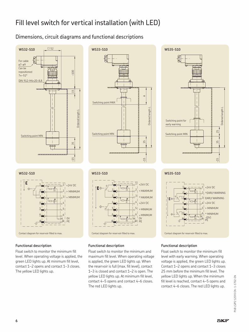
Fill level switch for vertical installation (with LED)
Dimensions, circuit diagrams and functional descriptions
DIN 912-M4×20-8,8
15~1
0035
~15
52WS32-S10
A35
~15
WS33-S10
2535
~15
WS35-S10
Switching point MIN
Ord
ered
lengt
h L
For cable
ø7–ø9
Can be
repositioned
7×~51°
Ord
ered
lengt
h L
Switching point MIN
Switching point MAX
Ord
ered
lengt
h L
Switching point MIN
Switching point for
early warning
5
6
1
2
3
4 YE
5
6M 0V
PE
> MINIMUM
= MINIMUM
1
2
3
GN
+24V DC
4
6 6
MPE0V
GN
YE4
5
3
2
1
= MAXIMUM
< MAXIMUM
+24V DC
4
5
3
2
1
> MINIMUM
= MINIMUM
+24V DC
RD
5
6
4
-(0V)PE
RDM
> MINIMUM
= MINIMUM
+24V DC
5
6
YE 4
1
3
2
1
> VORWARNUNG
VORWARNUNG
+24V DC
3
GN 2
WS32-S10 WS33-S10 WS35-S10
Functional description
Float switch to monitor the minimum fill
level. When operating voltage is applied, the
green LED lights up. At minimum fill level,
contact 1–2 opens and contact 1–3 closes.
The yellow LED lights up.
Functional description
Float switch to monitor the minimum and
maximum fill level. When operating voltage
is applied, the green LED lights up. When
the reservoir is full (max. fill level), contact
1–3 is closed and contact 1–2 is open. The
yellow LED lights up. At minimum fill level,
contact 4–5 opens and contact 4–6 closes.
The red LED lights up.
Functional description
Float switch to monitor the minimum fill
level with early warning. When operating
voltage is applied, the green LED lights up.
Contact 1–2 opens and contact 1–3 closes
25 mm before the minimum fill level. The
yellow LED lights up. When the minimum
fill level is reached, contact 4–5 opens and
contact 4–6 closes. The red LED lights up.
Contact diagram for reservoir filled to max. Contact diagram for reservoir filled to max. Contact diagram for reservoir filled to max.
EARLY WARNING
EARLY WARNING
MINIMUM
MINIMUM
MINIMUM
MINIMUM
MAXIMUM
MAXIMUM
MINIMUM
MINIMUM
6

PUB LS/P2 12593 EN · 1-1702-EN
Fill level switch for vertical installation (with LED)
Dimensions, circuit diagrams and functional descriptions
3515
M12x1
48
DIN 912-M4x22-8.8
WS32-S30
4835
15A
WS33-S30
1548
2535
WS35-S30
Ord
ered
lengt
h L
Switching point MIN
Switching point
for early warningOrd
ered
lengt
h L
Switching point MIN
Switching point MAX
Switching point MIN
Ord
ered
lengt
h L
= MINIMUMBU3
GN WH
M12x1
BK
2
RD 4-(0V)
BN1 +24V DC
> MINIMUMBK
M12x1
YE 4
BNBU
WH
1
GN
3
RD 2
+24V DC-(0V)
> MINIMUM
< MAXIMUM
M12x1
WH
BK
BUBN
RD
GN
YE
2
4
31
VORWARNUNG
> MINIMUM
-(0V)+24V DC
WS32-S30 WS33-S30 WS35-S30
Functional description
Float switch to monitor the minimum fill le-
vel. When operating voltage is applied, the
green LED lights up. At minimum fill level,
contact 1–4 opens and contact 1–2 closes.
The red LED lights up.
Functional description
Float switch to monitor the minimum and
maximum fill level. When operating voltage
is applied, the green LED lights up. When
the reservoir is full, contact 1–4 is open.
When the fluid level falls below the maxi-
mum, contact 1–4 closes and the yellow
LED lights up. When the minimum fill level
is reached, contact 1–2 opens and the red
LED lights up.
Functional description
Float switch to monitor the minimum fill
level with early warning. When operating
voltage is applied, the green LED lights up.
Contact 1–4 closes 25 mm before the mini-
mum fill level and the yellow LED lights up.
When the minimum fill level is reached,
contact 1–2 opens and the red LED lights
up.
Contact diagram for reservoir filled to max. Contact diagram for reservoir filled to max. Contact diagram for reservoir filled to max.
EARLY WARNINGMINIMUM
MAXIMUM
MINIMUM
MINIMUMMINIMUM
7
PUB LS/P2 12593 EN · 1-1702-EN
Max. 230 V AC
= MINIMUM
> MINIMUM
PE
3
2
11
2
3
> MINIMUM
Max. 230 V AC
= MAXIMUM
22
PE
33
11
22
33
11
PE
> MINIMUM
Max. 230 V AC
VORWARNUNG
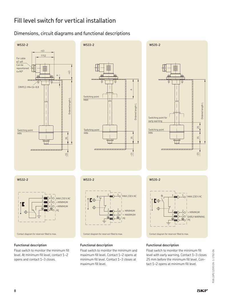
Fill level switch for vertical installation
Dimensions, circuit diagrams and functional descriptions
WS32-2 WS33-2 WS35-2
~15
~63
52
DIN912-M4×16-8.8
~43
9
35
WS32-2
~15
35A
WS33-2
~15
2535
WS35-2
Switching point
MIN
Ord
ered
lengt
h L
Ord
ered
lengt
h L
Switching point
MIN
Switching point
MAX
Ord
ered
lengt
h L
Switching point
MIN
Switching point for
early warning
For cable
ø7–ø9
Can be
repositioned
4×90°
Functional description
Float switch to monitor the minimum fill
level. At minimum fill level, contact 1–2
opens and contact 1–3 closes.
Functional description
Float switch to monitor the minimum and
maximum fill level. Contact 1–2 opens at
minimum fill level. Contact 1–3 closes at
maximum fill level.
Functional description
Float switch to monitor the minimum fill
level with early warning. Contact 1–3 closes
25 mm before the minimum fill level. Con-
tact 1–2 opens at minimum fill level.
Contact diagram for reservoir filled to max. Contact diagram for reservoir filled to max. Contact diagram for reservoir filled to max.
EARLY WARNING
MINIMUM
MINIMUMMINIMUM
MAXIMUM
MAX 230 V ACMAX 230 V ACMAX 230 V AC
MINIMUM
8

PUB LS/P2 12593 EN · 1-1702-EN
M12x1
2
3
4
1
WH
BU
BK
BN
NICHT BENUTZT
> MINIMUM
= MINIMUM
24V AC/DC
M12x1
1
2
3
4 = MAXIMUM
> MINIMUM
BN 24V AC/DC
BK
BU NICHT BENUTZT
WH > MINIMUM
24V AC/DC
NICHT BENUTZT
M12x1
BN
BK
BU
WH
1
2
3
4 VORWARNUNG
WS32-2-V57-A WS33-2-V57-A WS35-2-V57-A
3515
29
DIN 912-M4x20-8.8 M12x1
WS32-2-V57-A
1535
A
29
WS33-2-V57-A
3515
25
29
WS35-2-V57-A
Ord
ered
lengt
h L
Switching
point MIN
Switching point
for early warning
Ord
ered
lengt
h L
Switching point
MIN
Switching point
MAX
Switching point
MIN
Ord
ered
lengt
h L
Fill level switch for vertical installation
Dimensions, circuit diagrams and functional descriptions
Functional description
Float switch to monitor the minimum fill
level. At minimum fill level, contact 1–4
opens and contact 1–2 closes.
Functional description
Float switch to monitor the minimum and
maximum fill level. Contact 1–2 opens at
minimum fill level. Contact 1–4 closes at
maximum fill level.
Functional description
Float switch to monitor the minimum fill
level with early warning. Contact 1–4 closes
25 mm before the minimum fill level.
Contact 1–2 opens at minimum fill level.
Contact diagram for reservoir filled to max. Contact diagram for reservoir filled to max. Contact diagram for reservoir filled to max.
NOT USED NOT USED NOT USED
EARLY WARNING
MINIMUM
MINIMUM
MINIMUM
MAXIMUM
MINIMUM
9
PUB LS/P2 12593 EN · 1-1702-EN
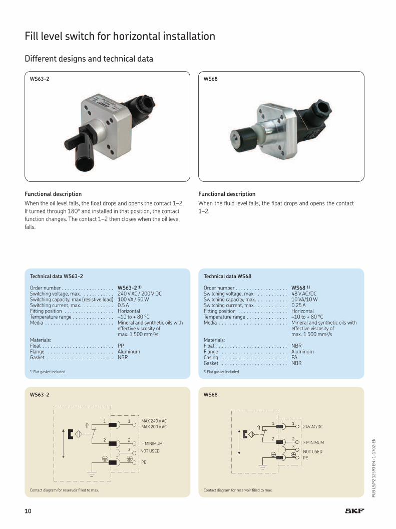
Fill level switch for horizontal installation
Different designs and technical data
WS63-2 WS68
Functional description
When the oil level falls, the float drops and opens the contact 1–2.
If turned through 180° and installed in that position, the contact
function changes. The contact 1–2 then closes when the oil level
falls.
Functional description
When the fluid level falls, the float drops and opens the contact
1–2.
Technical data WS63-2
Order number . . . . . . . . . . . . . . . . . . . WS63-2 1)
Switching voltage, max. . . . . . . . . . . . 240 V AC / 200 V DCSwitching capacity, max (resistive load) 100 VA / 50 WSwitching current, max. . . . . . . . . . . . 0.5 AFitting position . . . . . . . . . . . . . . . . . . HorizontalTemperature range . . . . . . . . . . . . . . . –10 to + 80 °CMedia . . . . . . . . . . . . . . . . . . . . . . . . . Mineral and synthetic oils with
effective viscosity of max. 1 500 mm2/s
Materials:Float . . . . . . . . . . . . . . . . . . . . . . . . . . PPFlange . . . . . . . . . . . . . . . . . . . . . . . . AluminumGasket . . . . . . . . . . . . . . . . . . . . . . . . NBR
2
1
3
2
1 MAX. 240V AC
NICHT BENUTZT
> MINIMUM
PE
MAX. 200V DC
WS63-2
Technical data WS68
Order number . . . . . . . . . . . . . . . . . . . WS68 1)
Switching voltage, max. . . . . . . . . . . . 48 V AC /DCSwitching capacity, max. . . . . . . . . . . . 10 VA/10 WSwitching current, max. . . . . . . . . . . . 0.25 AFitting position . . . . . . . . . . . . . . . . . . HorizontalTemperature range . . . . . . . . . . . . . . . –10 to + 80 °C Media . . . . . . . . . . . . . . . . . . . . . . . . . Mineral and synthetic oils with
effective viscosity of max. 1 500 mm2/s
Materials:Float . . . . . . . . . . . . . . . . . . . . . . . . . . NBRFlange . . . . . . . . . . . . . . . . . . . . . . . . AluminumCasing . . . . . . . . . . . . . . . . . . . . . . . . PAGasket . . . . . . . . . . . . . . . . . . . . . . . . NBR
2
1
PE
> MINIMUM2
3
24V AC/DC1
WS68
NOT USEDNOT USED
1) Flat gasket included 1) Flat gasket included
Contact diagram for reservoir filled to max. Contact diagram for reservoir filled to max.
MINIMUMMINIMUM
MAX 240 V AC
MAX 200 V AC
10
PUB LS/P2 12593 EN · 1-1702-EN
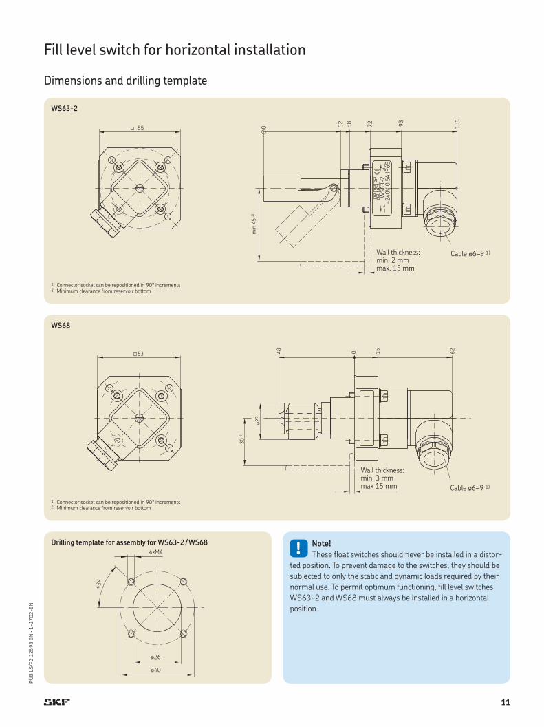
Fill level switch for horizontal installation
Dimensions and drilling template
131
93585255 720
~240
V 0,
5A IP
65W
S63-
2
min
45
2)
WS63-2
53 15 62048
ø23
30 2)
WS68
Wall thickness: min. 3 mmmax 15 mm
1) Connector socket can be repositioned in 90° increments2) Minimum clearance from reservoir bottom
Cable ø6–9 1)
Cable ø6–9 1)
45°
ø40
4×M4
ø26
Drilling template for assembly for WS63-2 / WS68!
Note!
These float switches should never be installed in a distor-
ted position. To prevent damage to the switches, they should be
subjected to only the static and dynamic loads required by their
normal use. To permit optimum functioning, fill level switches
WS63-2 and WS68 must always be installed in a horizontal
position.
Wall thickness: min. 2 mmmax. 15 mm
1) Connector socket can be repositioned in 90° increments2) Minimum clearance from reservoir bottom
11
SKF Lubrication Systems Germany GmbH
Plant Berlin
Motzener Str. 35/37 · 12277 Berlin
PO Box 970444 · 12704 Berlin
Germany
Tel. +49 (0)30 72002-0
Fax +49 (0)30 72002-111
This brochure was presented to you by:
Further brochures:
1-0103-EN Fittings and accessories
1-1202-EN Gear pump units
1-1730-EN Electric push-to-connect fittings
1-9201-EN Feeding lubricants with centralized lubrication systems
® SKF is a registered trademark of the SKF Group.
© SKF Group 2016The contents of this publication are the copyright of the publisher and may not be reproduced (even extracts) unless prior written permission is granted. Every care has been taken to ensure the accuracy of the information contained in this publication. but no liability can be accepted for any loss or damage whether direct, indirect or consequential, arising out of use of the information contained herein.
PUB LS/P2 12593 EN · August 2016 · 1-1702-EN
CAD models for products shown in
this brochure can be downloaded at:
skf-lubrication.partcommunity.com
!Important information on product usageSKF and Lincoln lubrication systems or their components are not approved for use with gases,
liquefied gases, pressurized gases in solution and fluids with a vapor pressure exceeding normal atmospheric pressure (1 013 mbar) by more than 0,5 bar at their maximum permissible temperature.
skf.com/lubrication