File in Section: 06 - Engine Service Bulletin Date: August ...

Service Bulletin
File in Section: -
Bulletin No.: PI0339C
Date: May, 2014
PRELIMINARY INFORMATION
Subject: Instrument Panel Cluster (IPC) Warning Lamps and/or MIL are Illuminated, DieselExhaust Fluid (DEF) Message Displayed, Various DTCs Set, Transmission May NotShift or Defaults to Second Gear (Inspect Wiring Harnesses for Chafing, ConnectorsNot Fully Seated, and Backed Out or Damaged Terminals, Repair as Needed)
Models: 2011-2014 Chevrolet Silverado 2500HD, 3500HD2011-2014 GMC Sierra 2500HD, 3500HDEquipped with 6.6L Duramax™ Diesel Engine RPO LGH or LML
Attention: Due to Model Year and vehicle build content, all of the Conditions/Concerns describedwithin this PI may not apply to all vehicles.
This PI has been revised to add the 2014 Chevrolet Silverado 2500HD, 3500HD and GMCSierra 2500HD, 3500HD Models and update the Labor Operation to the Global Labor Code
(GLC). Please discard PI0339B.
Condition/ConcernSome customers may comment on any of the following conditions:• A driver information center (DIC) message is displayed.• Instrument panel cluster (IPC) warning lamps are illuminated.• One or more diesel exhaust fluid (DEF) warning messages are displayed.• The malfunction indicator lamp (MIL) is illuminated.• The transmission may not shift or defaults to second gear.• The technician may observe on a scan tool one or more of the following DTCs set as Current or in History:
– DTC P0101: Mass Air Flow (MAF) Sensor Performance– DTC P0480: Cooling Fan Speed Output Circuit– DTC P0495: Cooling Fan Speed High– DTC P0657: Solenoid High Control Circuit Group 1– DTC P0658: Solenoid High Control Circuit Group 1 Low Voltage– DTC P0706: Transmission Range Sensor Circuit Performance– DTC P0708: Transmission Range Switch Circuit High Voltage– DTC P0712: Transmission Fluid Temperature (TFT) Sensor Circuit Low Voltage– DTC P0713: Transmission Fluid Temperature (TFT) Sensor Circuit High Voltage– DTC P0717: Input Speed Sensor Circuit Low Voltage– DTC P0722: Output Speed Sensor Circuit Low Voltage– DTC P0751: Shift Solenoid (SS) 1 Valve Performance - Stuck Off– DTC P0752: Shift Solenoid (SS) 1 Valve Performance - Stuck On– DTC P0756: Shift Solenoid (SS) 2 Valve Performance - Stuck Off– DTC P0757: Shift Solenoid (SS) 2 Valve Performance - Stuck On– DTC P0761: Shift Solenoid (SS) 3 Valve Performance - Stuck Off– DTC P0762: Shift Solenoid (SS) 3 Valve Performance - Stuck On– DTC P0842: Transmission Fluid Pressure (TFP) Switch 1 Circuit Low Voltage

– DTC P0843: Transmission Pressure Switch 1 Circuit High Voltage– DTC P0847: Transmission Fluid Pressure (TFP) Switch 2 Circuit Low Voltage– DTC P0848: Transmission Pressure Switch 2 Circuit High Voltage– DTC P0872: Transmission Fluid Pressure (TFP) Switch 3 Circuit Low Voltage– DTC P0873: Transmission Pressure Switch 3 Circuit High Voltage– DTC P0877: Transmission Fluid Pressure (TFP) Switch 4 Circuit Low Voltage– DTC P0878: Transmission Fluid Pressure (TFP) Switch 4 Circuit High Voltage– DTC P0960: Main Modulation/Line Pressure Control (PC) Solenoid Control Circuit Open– DTC P0962: Main Modulation/Line Pressure Control (PC) Solenoid Control Circuit Low Voltage– DTC P0964: Pressure Control (PC) Solenoid 2 Control Circuit Open– DTC P0966: Pressure Control (PC) Solenoid 2 Control Circuit Low Voltage– DTC P0972: Shift Solenoid (SS) 1 Control Circuit Open– DTC P0973: Shift Solenoid (SS) 1 Control Circuit Low Voltage– DTC P0975: Shift Solenoid (SS) 2 Control Circuit Open– DTC P0976: Shift Solenoid (SS) 2 Control Circuit Low Voltage– DTC P0979: Shift Solenoid (SS) 3 Control Circuit Low Voltage– DTC P2669: Solenoid High Control Circuit Group 2– DTC P2670: Solenoid High Control Circuit Group 2 Low Voltage– DTC P2727: Pressure Control (PC) Solenoid 1 Open– DTC P2729: Pressure Control (PC) Solenoid 1 Control Circuit Low Voltage– DTC P2761: Torque Converter Clutch (TCC) Pressure Control (PC) Solenoid Control Circuit– DTC P2764: Torque Converter Clutch (TCC) Pressure Control (PC) Solenoid Control Circuit Low Voltage– DTC P2453: Diesel Particulate Filter (DPF) Differential Pressure Sensor Performance– DTC P2454: Diesel Particulate Filter Differential Pressure Sensor Circuit Low Voltage– DTC P11DB: NOx Sensor 1 Current Performance– DTC P11DC: NOx Sensor 2 Current Performance– DTC P220B: NOx Sensor 2 Supply Voltage Circuit– DTC P20BB: Reductant Heater 1 Control Circuit Low Voltage– DTC P20BD: Reductant Heater 2 Control Circuit– DTC P20BF: Reductant Heater 2 Control Circuit Low Voltage– DTC P20CC: Exhaust Aftertreatment Fuel Injector Performance– DTC P20C3 : Reductant Heater 3 Control Circuit Low Voltage– DTC P22A7: NOx Sensor 2 Heater Feedback Performance– DTC P242C: Exhaust Gas Temperature Sensor 3 Circuit Low Voltage– DTC P246F: Exhaust Gas Temperature Sensor 4 Performance– DTC U029D: Lost Communication with NOX Sensor Module 1– DTC U029E: Lost Communication with NOX Sensor Module 2
This may be caused by, but not limited to, any of the following:
Condition #1
The wiring harness of connector X107 is chafing on one of the generators on trucks equipped with dual generatorsand/or the assist lever for connector X107 is not fully or properly seated or has backed out or damaged terminals.
Condition #2
The assist lever for connector X300 is not fully or properly seated or has backed out or damaged terminals.
Condition #3
The assist lever for connector X395 is not fully or properly seated or has backed out or damaged terminals.
Condition #4
Chafing of the insulation of the wiring harness that is routed by the left front control arm.
Condition #5
Chafing of the insulation of the wiring harness immediately adjacent to harness connector X107 on the EGR valve.
Recommendation/Instructions
Do This Don't Do This
Ensure any connector TPAis fully seated (TPA iscentered in the check
window).
DO NOT replace any controlmodule or wiring harnessuntil you have followed thisprocedure in its entirety.Depending on the vehicle
build, some of theprocedures may not be
applicable.
Repair and reroute anywiring harness as needed.
Repair any connectorterminals that are damaged,have poor connections or do
not mate properly.
Notice: For all connector and component locations and all wiring harness routing information, Go to > SI >Build the Vehicle > Service Manual/Bulletins > Power and Signal Distribution > Wiring Systems and PowerManagement > Component Locator > Master Electrical Component List.
Determining the Condition to Diagnose1. Perform the Diagnostic System Check - Vehicle.2. Record any DTC for reference to use in the following five Recommendation/Instructions - Condition procedures
as directed.
⇒ If DTC P0101, P20BB, P20BD, P20BF, P20C3, P11DC, DTC P220B, P22A7 or U029E are set or any dieselexhaust fluid (DEF) DTCs are set or DEF messages displayed proceed to Condition #1.
⇒ If DTC P11DB, P11DC, P2453, P2454, P20CC, P242C, P246F, U029D or U029E are set, proceed toCondition #2.
⇒ If DTC U029D or U029E are set, proceed to Condition #3.
⇒ If DTC P0480, P0495, P0657, P0658, P0706, P0708, P0712, P0713, P0717, P0722, P0751, P0752, P0756,P0757, P0761, P0762, P0842, P0843, P0847, P0848, P0872, P0873, P0877, P0878, P0960, P0962, P0964,P0966, P0972, P0973, P0975, P0976, P0979, P2453, P2454, P2669, P2670, P2727, P2729, P2761, orP2764 are set, proceed to Condition #4.
⇒ If DTC P220B, U029D or U029E are set, proceed to Condition #5.
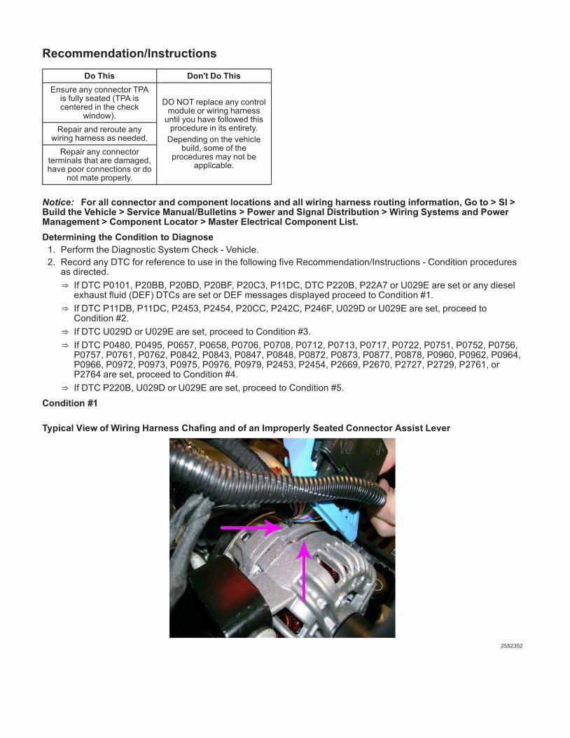
Condition #1
Typical View of Wiring Harness Chafing and of an Improperly Seated Connector Assist Lever
2552352
2552508
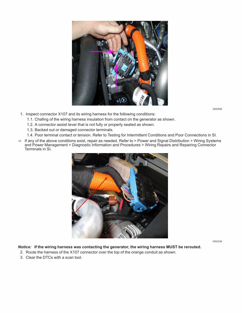
1. Inspect connector X107 and its wiring harness for the following conditions:1.1. Chafing of the wiring harness insulation from contact on the generator as shown.1.2. A connector assist lever that is not fully or properly seated as shown.1.3. Backed out or damaged connector terminals.1.4. Poor terminal contact or tension. Refer to Testing for Intermittent Conditions and Poor Connections in SI.
⇒ If any of the above conditions exist, repair as needed. Refer to > Power and Signal Distribution > Wiring Systemsand Power Management > Diagnostic Information and Procedures > Wiring Repairs and Repairing ConnectorTerminals in SI.
2552339
Notice: If the wiring harness was contacting the generator, the wiring harness MUST be rerouted.2. Route the harness of the X107 connector over the top of the orange conduit as shown.3. Clear the DTCs with a scan tool.
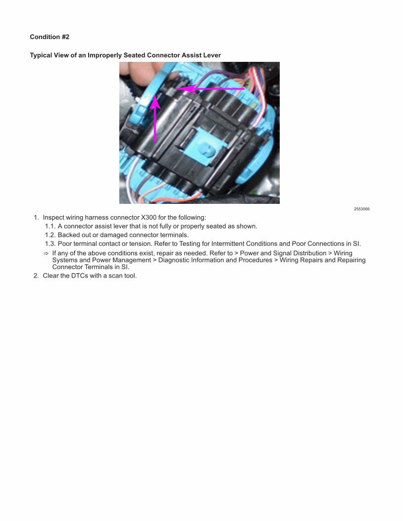
Condition #2
Typical View of an Improperly Seated Connector Assist Lever
2553066
1. Inspect wiring harness connector X300 for the following:1.1. A connector assist lever that is not fully or properly seated as shown.1.2. Backed out or damaged connector terminals.1.3. Poor terminal contact or tension. Refer to Testing for Intermittent Conditions and Poor Connections in SI.
⇒ If any of the above conditions exist, repair as needed. Refer to > Power and Signal Distribution > WiringSystems and Power Management > Diagnostic Information and Procedures > Wiring Repairs and RepairingConnector Terminals in SI.
2. Clear the DTCs with a scan tool.

Condition #3
Typical View of an Improperly Seated Connector Assist Lever
2553066
1. Inspect wiring harness connector X395 for the following:1.1. A connector assist lever that is not fully or properly seated as shown.1.2. Backed out or damaged connector terminals.1.3. Poor terminal contact or tension. Refer to Testing for Intermittent Conditions and Poor Connections in SI.
⇒ If any of the above conditions exist, repair as needed. Refer to > Power and Signal Distribution > WiringSystems and Power Management > Diagnostic Information and Procedures > Wiring Repairs and RepairingConnector Terminals in SI.
2. Clear the DTCs with a scan tool.

Condition #4
Typical View of Improper Wiring Harness Contact Points in the Control Arm Area
2552582
1. Inspect the wiring harness insulation for chafing from contact on the left front control arm and from contact onthe charge air cooler (CAC) pipe, in the areas as shown by the arrows.
⇒ If chafing of the wiring harness insulation is observed, repair as needed. Refer to > Power and SignalDistribution > Wiring Systems and Power Management > Diagnostic Information and Procedures > WiringRepairs in SI.
2. Clear the DTCs with a scan tool.
Condition #5
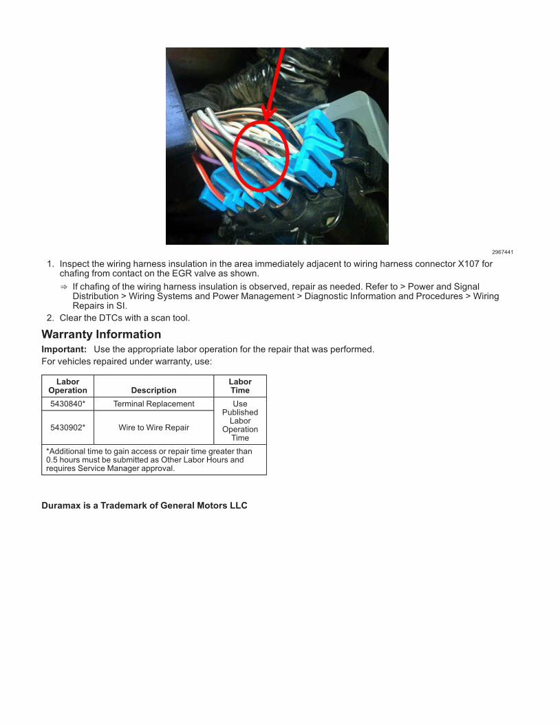
Typical View of Wiring Harness Chafing From Contact With the EGR Valve
2967329
2967441
1. Inspect the wiring harness insulation in the area immediately adjacent to wiring harness connector X107 forchafing from contact on the EGR valve as shown.
⇒ If chafing of the wiring harness insulation is observed, repair as needed. Refer to > Power and SignalDistribution > Wiring Systems and Power Management > Diagnostic Information and Procedures > WiringRepairs in SI.
2. Clear the DTCs with a scan tool.
Warranty InformationImportant: Use the appropriate labor operation for the repair that was performed.For vehicles repaired under warranty, use:
LaborOperation Description
LaborTime
5430840* Terminal Replacement UsePublishedLabor
OperationTime
5430902* Wire to Wire Repair
*Additional time to gain access or repair time greater than0.5 hours must be submitted as Other Labor Hours andrequires Service Manager approval.
Duramax is a Trademark of General Motors LLC