Figure 6-19 — Logic operations comparison...
71
Figure 6-19 — Logic operations comparison chart. 6-23
Transcript of Figure 6-19 — Logic operations comparison...

Figure 6-19 — Logic operations comparison chart.
6-23
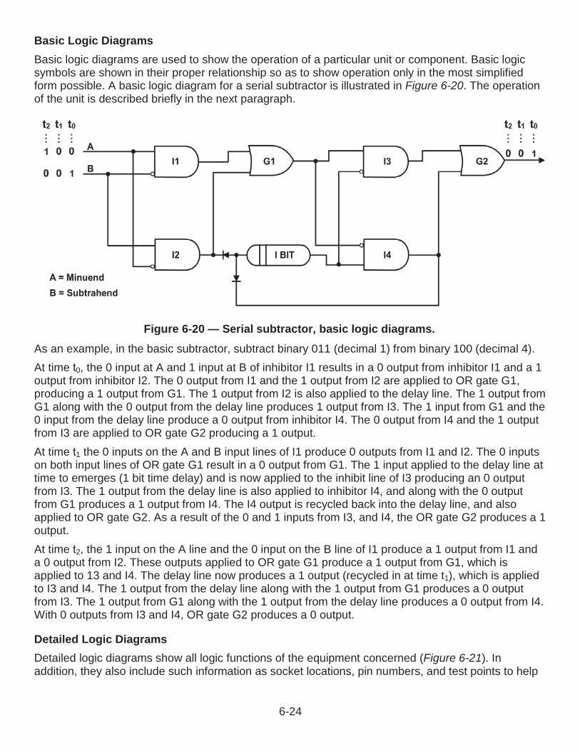
Basic Logic DiagramsBasic logic diagrams are used to show the operation of a particular unit or component. Basic logic symbols are shown in their proper relationship so as to show operation only in the most simplifiedform possible. A basic logic diagram for a serial subtractor is illustrated in Figure 6-20. The operation of the unit is described briefly in the next paragraph.
As an example, in the basic subtractor, subtract binary 011 (decimal 1) from binary 100 (decimal 4). At time 0, the 0 input at A and 1 input at B of inhibitor I1 results in a 0 output from inhibitor I1 and a 1 output from inhibitor I2. The 0 output from I1 and the 1 output from I2 are applied to OR gate G1,producing a 1 output from G1. The 1 output from I2 is also applied to the delay line. The 1 output fromG1 along with the 0 output from the delay line produces 1 output from I3. The 1 input from G1 and the 0 input from the delay line produce a 0 output from inhibitor I4. The 0 output from I4 and the 1 outputfrom I3 are applied to OR gate G2 producing a 1 output.At time 1 the 0 inputs on the A and B input lines of I1 produce 0 outputs from I1 and I2. The 0 inputs on both input lines of OR gate G1 result in a 0 output from G1. The 1 input applied to the delay line attime to emerges (1 bit time delay) and is now applied to the inhibit line of I3 producing an 0 outputfrom I3. The 1 output from the delay line is also applied to inhibitor I4, and along with the 0 outputfrom G1 produces a 1 output from I4. The I4 output is recycled back into the delay line, and also applied to OR gate G2. As a result of the 0 and 1 inputs from I3, and I4, the OR gate G2 produces a 1output.At time 2, the 1 input on the A line and the 0 input on the B line of I1 produce a 1 output from I1 and a 0 output from I2. These outputs applied to OR gate G1 produce a 1 output from G1, which isapplied to 13 and I4. The delay line now produces a 1 output (recycled in at time t1), which is appliedto I3 and I4. The 1 output from the delay line along with the 1 output from G1 produces a 0 outputfrom I3. The 1 output from G1 along with the 1 output from the delay line produces a 0 output from I4.With 0 outputs from I3 and I4, OR gate G2 produces a 0 output.
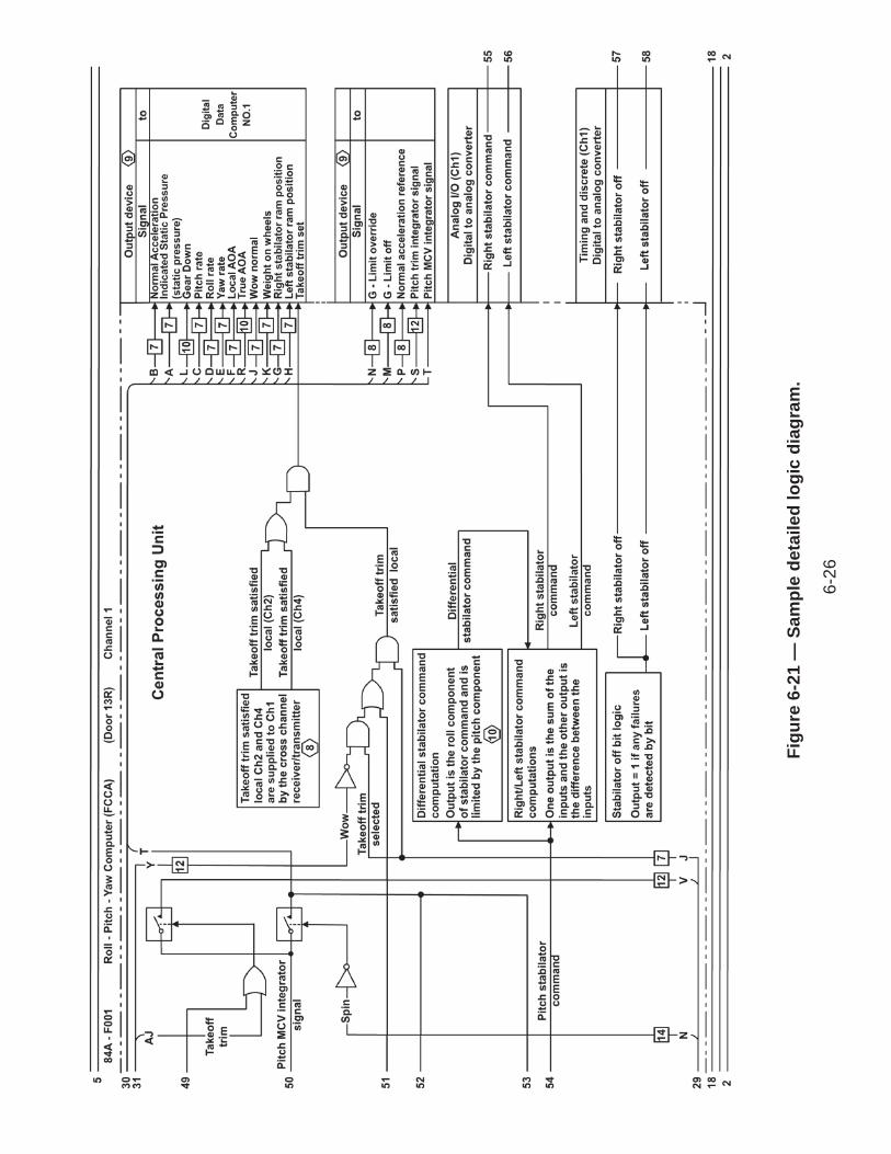
Detailed Logic DiagramsDetailed logic diagrams show all logic functions of the equipment concerned (Figure 6-21). In addition, they also include such information as socket locations, pin numbers, and test points to help
Figure 6-20 — Serial subtractor, basic logic diagrams.
6-24

in troubleshooting. The detailed logic diagram for a complete unit may consist of many separate sheets.All input lines shown on each sheet of a detailed logic diagram are tagged to show the origin of theinputs. Likewise, all output lines are tagged to show destination. In addition, each logic function shown on the sheet is tagged to identify the function hardware and to show function location both on the diagram and within the equipment.
6-25
Figu
re 6
-21
—Sa
mpl
e de
taile
d lo
gic
diag
ram
.
6-26
End of Chapter 6
Electrical and Electronics PrintsReview Questions6-1. What type of diagram shows a picture or sketch of various components of a specific system?
A. IsometricB. PictorialC. SchematicD. Wiring
6-2. What type of diagram is used to locate a component within a system?
A. IsometricB. PictorialC. SchematicD. Wiring
6-3. What type of diagram uses symbols to represent components in a circuit?
A. IsometricB. PictorialC. SchematicD. Wiring
6-4. What type of diagram is a detailed diagram of each circuit installation showing all connectors, terminal boards, and electrical components of a circuit?
A. IsometricB. PictorialC. SchematicD. Wiring
6-5. The new electrical cable tag system consists of how many parts?
A. OneB. TwoC. ThreeD. Four
6-6. What type of diagram is supplied for each shipboard electrical system?
A. Electrical troubleshootingB. Ground fault isolationC. Isometric deck planD. Isometric wiring
6-27

6-7. What type of print is used by the shipyard electrician to lay out the work for a number of cables without referring to individual isometric wiring diagrams?
A. BlockB. ConnectionC. Deck planD. Pictorial
6-8. What type of diagram is a valuable troubleshooting tool?
A. BlockB. ConnectionC. Deck planD. Pictorial
6-9. Aircraft graphic symbols are drawn according to what standard?
A. Institute of Electrical and Electronic Engineers Standard 315AB. Institute of Electrical and Electronic Engineers Standard 513AC. Military Specification: Wiring, Aerospace Vehicle, SAE-AS50441D. Military Specification: Wiring, Aerospace Vehicle, SAE-AS58551
6-10. Aircraft electrical wiring diagrams show what type of information on all electrical systems?
A. BasicB. DetailedC. SequentialD. Troubleshooting
6-11. Aircraft wire and cable identification is a combination of what two markings?
A. Letters and numbersB. Symbols and lettersC. Numbers and symbolsD. Symbols and classification label
6-12. In aircraft wiring identification, what letters are not used?
A. I and LB. I and OC. O and QD. P and O
6-13. Shipboard electronic prints include what types of drawings?
A. Advanced and basicB. Elementary and advancedC. Isometric and advancedD. Isometric and elementary
6-28

6-14. A reference designation is a combination of letters and numbers used to identify the various parts and components on electronic drawings, diagrams, and what other item?
A. Parts listB. Parts catalogC. Wiring scheduleD. Electrical installation guide
6-15. Aircraft electronic wiring diagrams fall into what two basic classes?
A. Basic and advancedB. Block and interconnectingC. Wiring and blockD. Wiring and interconnecting
6-16. Computers operate entirely on the principle of logic using what two conditions to make aprogrammed decision?
A. Logic and reasonB. No and prohibitC. True and falseD. Yes and or
6-17. The symbolic logic operations used in computers are based on what algebraic system?
A. AlgorithmB. BooleanC. MonomialD. Permutation
6-18. Logic operations consist of AND, OR, and what other basic operation?
A. IFB. ISC. NOTD. THEN
6-29

RATE TRAINING MANUAL – User Update SWOS makes every effort to keep their manuals up-to-date and free of technical errors. We appreciate your help in this process. If you have an idea for improving this manual, or if you find an error, a typographical mistake, or an inaccuracy in SWOS manuals, please write or e-mail us, using this form or a photocopy. Be sure to include the exact chapter number, topic, detailed description, and correction, if applicable. Your input will be brought to the attention of the Technical Review Committee. Thank you for your assistance.Write: SWOS Project Manager
1534 Piersey Street Suite 321Norfolk, VA 23511-2613COMM: (757) 444-5332DSN: 564-5332
E-mail: Refer to the SWOS Norfolk page on the NKO Web page for current contact information.
Rate____ Course Name_____________________________________________
Revision Date__________ Chapter Number____ Page Number(s)____________
Description _____________________________________________________________________________________________________________________________________________________________________________________________
(Optional) Correction _____________________________________________________________________________________________________________________________________________________________________________________________
(Optional) Your Name and Address _____________________________________________________________________________________________________________________________________________________________________________________________
6-30

CHAPTER 7
ARCHITECTURAL AND STRUCTURAL STEEL DRAWINGSArchitectural and structural steel drawings are generally considered to be the drawings of steel, wood, concrete, and other materials used to construct buildings, ships, planes, bridges, towers, tanks, and so on. This chapter discusses the common architectural and structural shapes and symbolscommonly used for architectural and structural steel drawings, and describe the common types of drawings used in the fabrication and erection of steel structures.
LEARNING OBJECTIVESWhen you have completed this chapter, you will be able to do the following:
1. Recognize the elements of architectural drawings.2. Identify various types of architectural symbols.3. Recognize the elements of structural steel drawings.4. Identify various types of structural symbols.5. Identify various types of construction drawings.
A building project may be broadly divided into two major phases, the design phase and the construction phase. First, the architect conceives the building, ship, or aircraft in his or her mind, and then sets down the concept on paper in the form of presentation drawings, which are usually drawn in perspective by using pictorial drawing techniques.The architect and engineer work together to decide upon materials and construction methods. The engineer determines the loads the supporting structural members will carry and the strength each member must have to bear the loads. He or she also designs the mechanical systems of the structure, such as heating, lighting, and plumbing systems. The end result is the preparation of architectural and engineering design sketches that will aid in preparing the construction drawings. These construction drawings, plus the specifications, are the chief sources of information for the supervisors and craftsmen who carry out the construction.
STRUCTURAL SHAPES AND MEMBERS
ShapesThe three most common types of structural members are the W-shape (wide flange), the S-shape (American Standard I-beam), and the C-shape (American Standard channel). These three types are identified by the nominal depth, in inches, along the web and the weight per foot of length, in pounds. As an example, a W 12 x 27 indicates a W-shape (wide flange) with a web 12 inches deep and a weight of 27 pounds per linear foot.The cross-sectional views of the W-, S-, and C-shapes are illustrated in Figure 7-2. The difference between the W-shape and the S-shape is in the design of the inner surfaces of the flange. The W-
7-1

shape has parallel inner and outer flange surfaces with a constant thickness, while the S-shape has a slope of approximately 17 degrees on the inner flange surfaces. The C-shape is similar to the S-shape in that its inner flange surface is also sloped approximately 17 degrees.
W-ShapeThe W shape is a structural member whose cross section forms the letter H and is the most widely used structural member. It is designed so that its flanges provide strength in a horizontal plane, while the web gives strength in a vertical plane. W-shapes are used as beams, columns, and truss members, and in other load-bearing applications.
Bearing PileThe bearing pile (HP-shape) is almost identical to the W-shape. The only difference is that the flange thickness and web thickness of the bearing pile are equal, whereas the W-shape has different web and flange thicknesses. Figure 7-2 — Cross section view of the W-,
S-, and C-shape structural members.
Figure 7-1 — Structural shapes and designations.
7-2

S-ShapeThe S-shape (American Standard I-beam) is distinguished by its cross section being shaped like the letter I. S-shapes are used less frequently than W-shapes since the S-shapes possess less strength and are less adaptable than W-shapes.
C-ShapeThe C-shape (American Standard channel) has a cross section somewhat similar to the letter C. It is especially useful in locations where a single flat face without outstanding flanges on one side is required. The C-shape is not very efficient for a beam or column when used alone. However, efficient built-up members may be constructed of channels assembled together with other structural shapes and connected by rivets or welds.
ChannelsA cross section of a channel is similar to the squared letter C. Channels are identified by their nominal depth and weight per foot. For example, the American Standard channel notation C9 x 13.4 in Figure 7-1 shows a nominal depth of 9 inches and a weight of 13.4 pounds per linear foot, Channels are principally used in locations where a single flat face without outstanding flanges on a side is required. However, the channel is not very efficient as a beam or column when used alone. But the channelsmay be assembled together with other structural shapes and connected by rivets or welds to form efficient built-up members.
AnglesAn angle (Figure 7-3) is a structural shape whose cross section resembles the letter L. Two types arecommonly used: an equal-leg angle and an unequal-leg angle. The angle is identified by thedimension and thickness of its legs, for example,angle 6 inches by 4 inches by inch. Thedimension of the legs should be obtained bymeasuring along the outside of the backs of thelegs. When an angle has unequal legs, the dimension of the wider leg is given first, as in the Figure 7-3 — Angles.example just cited. The third dimension applies tothe thickness of the legs, which always have equal thickness. Angles may be used in combinations oftwo or four to form main members. A single angle may also be used to connect main parts together.
PlatesGenerally, a main point to remember about plate is that it has a width of greater than 8 inches and athickness of inch or greater. Plates are generally used as connections between other structuralmembers or as component parts of built-up structural members. Plates cut to specific sizes may be obtained in widths ranging from 8 inches to 120 inches or more, and in various thicknesses. Theedges of these plates may be cut by shears (sheared plates) or be rolled square (universal millplates).Frequently, plates are referred to by their thickness and width in inches, as plate inch x 24 inches.
7-3

40-pound plate. In practice, you mayhear plate referred to by its approximate weight per square foot for a specifiedthickness. An example is 20-poundplate, which indicates a -inch plate. The designations generally used for flat steel have been established by the American Iron and Steel Institute (AISI). Flat steel is designated as bar, strip, sheet, or plate, according to the thickness of the material, the width of the material, and (to some extent) the rolling process to which it was subjected.
TeesA structural tee is made by slitting a standard I- or H- beam through the center of its web, thus forming two T-shapes from each beam. In dimensioning, the structural tee symbol is preceded by the letters ST. For example, the symbol ST 5 WF 10.5 means the tee has a nominal depth of 5 inches, a wide flange, and weighs 10.5 pounds per linear foot. A rolled tee is a manufactured shape. In dimensioning, the rolled tee symbol is preceded by the letter T. The dimension T 4 x 3 x 9.2 means the rolled T has a 4-inch flange, a nominal depth of 3 inches, and a weight of 9.2 pounds per linear foot.
ZeeThese shapes are noted by depth, flange width, andweight per linear foot. Therefore, Z 6 x 3 x 15.7means the zee is 6 inches in depth, has a 3 -inchflange, and weighs 15.7 pounds per linear foot.
Fla BarThe structural shape referred to as bar has a width of 8 inches or less and a thickness greater than of an inch. The edges of bars usually are rolled square, likeuniversal mill plates. The dimensions are expressed in asimilar manner as that for plates, for instance, bar 6 inches by inch. Bars are available in a variety of cross-sectional shapes—round, hexagonal, octagonal,square, and flat. Four different shapes are illustrated in
ColumnsTypically, wide flange members, as nearly square in cross section as possible, are used for columns, but sometimes large diameter pipe is used, even though pipe columns can present connecting difficulties when you are attaching other members (Figure 7-6). Columns may also be fabricated by welding or bolting together a number of other rolled shapes, usually angles and plates (Figure 7-7).
Figure 7-4 — Weight and thickness of a steel plate.
Figure 7-5 — Bars.
7-4

GirdersGirders are the primary horizontal members of a steel frame structure. They span from column to column and are usually connected on top of the columns with cap plates (bearing connections) (Figure 7-8). An alternate method is the seated connection (Figure 7-9). The girder is attached to the flange of the column using angles, with one leg extended along the girder flange and the other against the column. The function of the girders is to support the intermediate floor beams.
MembersThe main parts of a structure are the load-bearing members. These support and transfer the loads on the structure while remaining equal to each other. The places where members are connected to other members are
called joints. The total sum of the load supported by the structural members at a particular instant is equal to the total dead load plus the total live load.The total dead load is the total weight of the structure, which gradually increases as the structure rises and remains constant once it is complete. The total live load is the total weight of movable objects, such as people, furniture, and bridge traffic, the structure happens to be supporting at a particular instant.
Figure 7-6 — Girder span on pipe columns.
Figure 7-7 — Built-up column section.
Figure 7-8 — Girder span on a wide flange column.
Figure 7-9 — Seated connections.7-5

Figure 7-10 — Typical light frame construction.
A structure transmits live loads through the various load-bearing structural members to the ultimate support of the earth. Look at Figure 7-10, which illustrates both horizontal and vertical members of a typical light frame structure.
First, horizontal members provide immediate or direct support for the live loads. Vertical members, in turn, support the horizontal members. Finally, the vertical members are supported by foundations or footings, which are supported by the earth. The weight of the roof material is distributed over the top supporting members and transferred through all joining members to the soil.The ability of the earth to support a load is called its soil-bearing capacity. This varies considerably with different types of soil. A soil of a given bearing capacity bears a heavier load on a wide foundation or footing than on a narrow one. Loads are covered in much greater detail in the Builder Advanced rate training manual. This section is meant to be a brief introduction to the concept of load.
Vertical MembersIn heavy construction, vertical structural members are high-strength columns. In large buildings, these are called pillars. Outside wall columns and inside bottom floor columns usually rest directly on footings. Outside wall columns usually extend from the footing or foundation to the roof line. Inside bottom floor columns extend upward from footings or foundations to the horizontal members, which,
7-6
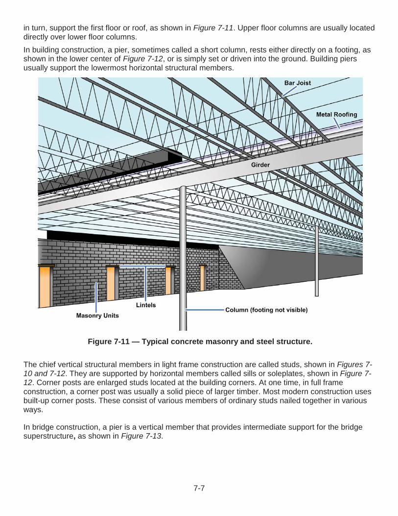
Figure 7-11 — Typical concrete masonry and steel structure.
in turn, support the first floor or roof, as shown in Figure 7-11. Upper floor columns are usually located directly over lower floor columns.In building construction, a pier, sometimes called a short column, rests either directly on a footing, as shown in the lower center of Figure 7-12, or is simply set or driven into the ground. Building piers usually support the lowermost horizontal structural members.
The chief vertical structural members in light frame construction are called studs, shown in Figures 7-10 and 7-12. They are supported by horizontal members called sills or soleplates, shown in Figure 7-12. Corner posts are enlarged studs located at the building corners. At one time, in full frame construction, a corner post was usually a solid piece of larger timber. Most modern construction uses built-up corner posts. These consist of various members of ordinary studs nailed together in various ways.
In bridge construction, a pier is a vertical member that provides intermediate support for the bridge superstructure, as shown in Figure 7-13.
7-7
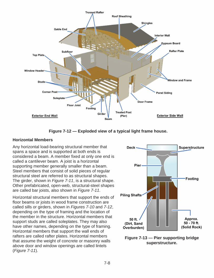
Figure 7-12 — Exploded view of a typical light frame house.
Horizontal MembersAny horizontal load-bearing structural member that spans a space and is supported at both ends is considered a beam. A member fixed at only one end is called a cantilever beam. A joist is a horizontal supporting member generally smaller than a beam.Steel members that consist of solid pieces of regular structural steel are referred to as structural shapes. The girder, shown in Figure 7-11, is a structural shape. Other prefabricated, open-web, structural-steel shapes are called bar joists, also shown in Figure 7-11.Horizontal structural members that support the ends of floor beams or joists in wood frame construction are called sills or girders, shown in Figures 7-10 and 7-12,depending on the type of framing and the location of the member in the structure. Horizontal members that support studs are called soleplates. They may also have other names, depending on the type of framing. Horizontal members that support the wall ends of rafters are called rafter plates. Horizontal members that assume the weight of concrete or masonry walls above door and window openings are called lintels(Figure 7-11).
Figure 7-13 — Pier supporting bridge superstructure.
7-8

Figure 7-14 — A truss rafter.
The horizontal or inclined members that provide support to a roof are called rafters (Figure 7-14). The lengthwise member at a right angle to the rafters, which supports the peak ends of the rafters in a roof, is called the ridge. The ridge may be called a ridgeboard, the ridge piece, or the ridgepole.Lengthwise members other than ridges are called purlins. In wood frame construction, the wall ends of rafters are supported on horizontal members called rafter plates, which are in turn supported by the outside wall studs. In concrete or masonry construction, the wall ends of rafters may be anchored directly on the walls or on plates bolted to the walls.
TrussesA beam of given strength, without intermediate supports below; can support a given load over only a specific maximum span. When the span is wider than this maximum space, the beam requires intermediate supports such as columns. Sometimes it is either not feasible or impossible to increase the beam size or to install intermediate supports. In such cases, a truss provides the required support. A truss is a combination of members, such as beams, bars, and ties, usually arranged in triangular units, that forms a rigid framework for supporting loads over a span.The basic components of a roof truss are the top and bottom chords and the web members. The top chords serve as roof rafters. The bottom chords act as ceiling joists. The web members run between the top and bottom chords. The truss parts are usually made of 2 by 4 inch or 2 by 6 inch material and tied together with metal or plywood gusset plates, shown in Figure 7-14.
WELDED AND RIVETED STEEL STRUCTURESThe following paragraphs will discuss welded and riveted steel structures and will give examples of both methods used to make trusses.
Welded Steel StructuresGenerally, welded connections are framed or seated just as they are in riveted connections, which we will discuss later. However, welded connections are more flexible. The holes used to bolt or pin pieces together during welding are usually drilled in the fabrication shop. Beams are not usually welded directly to columns. The procedure produces a rigid connection and results in severe bending that stresses the beam, which must be resisted by both the beam and the weld.
7-9
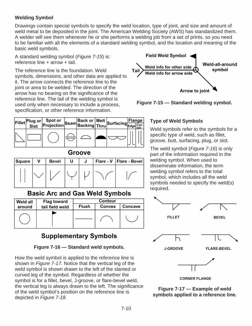
Welding SymbolDrawings contain special symbols to specify the weld location, type of joint, and size and amount of weld metal to be deposited in the joint. The American Welding Society (AWS) has standardized them. A welder will see them whenever he or she performs a welding job from a set of prints, so you need to be familiar with all the elements of a standard welding symbol, and the location and meaning of the basic weld symbols.A standard welding symbol (Figure 7-15) is: reference line + arrow + tail.The reference line is the foundation. Weld symbols, dimensions, and other data are applied to it. The arrow connects the reference line to the joint or area to be welded. The direction of the arrow has no bearing on the significance of the reference line. The tail of the welding symbol is used only when necessary to include a process, specification, or other reference information.
Type of Weld SymbolsWeld symbols refer to the symbols for a specific type of weld, such as fillet, groove, butt, surfacing, plug, or slot.The weld symbol (Figure 7-16) is only part of the information required in the welding symbol. When used to disseminate information, the term welding symbol refers to the total symbol, which includes all the weld symbols needed to specify the weld(s) required.
How the weld symbol is applied to the reference line is shown in Figure 7-17. Notice that the vertical leg of the weld symbol is shown drawn to the left of the slanted or curved leg of the symbol. Regardless of whether the symbol is for a fillet, bevel, J-groove, or flare-bevel weld, the vertical leg is always drawn to the left. The significance of the weld symbol’s position on the reference line is depicted in Figure 7-18.
Figure 7-16 — Standard weld symbols.
Figure 7-17 — Example of weld symbols applied to a reference line.
Figure 7-15 — Standard welding symbol.
7-10

When only one edge of a joint is to be beveled, it is necessary to show which member is to be beveled (Figure 7-19). When such a joint is specified, the arrow of the welding symbol points with a definite break toward the member to be beveled. Other weld symbols may be added to a welding symbol as necessary to communicate all the information needed for the weld.However, regardless of the direction of the arrow, all information applied to the reference line on a welding symbol is read from left to right. A listing of welding symbols is shown in Figure 7-20.
Figure 7-18 — Example of specifying weld location.
Figure 7-19— Example of arrowhead indicating bevel plate.
7-11
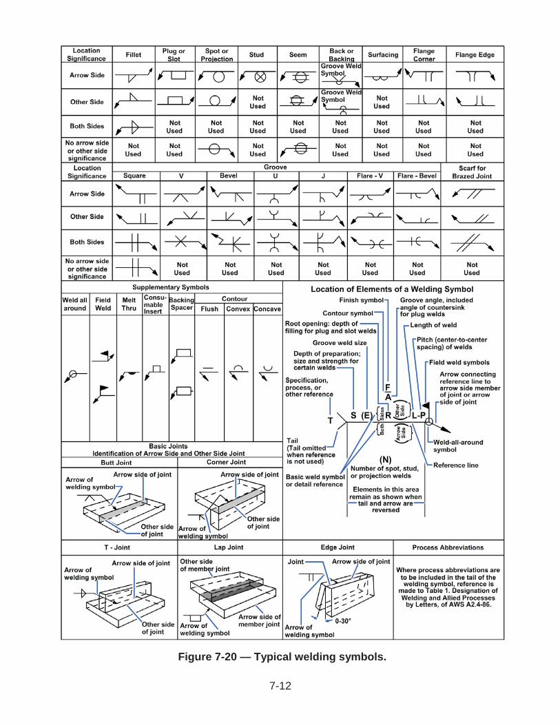
Figure 7-20 — Typical welding symbols.
7-12

DimensioningNotice in Figure 7-21 that some specified information has designated locations.
The size, length, pitch (center-to-center spacing), groove angle, and root opening of a weld all have designated locations. These locations are determined by the side of the reference line on which the weld symbol is placed.
SupplementaryBesides the basic weld symbols, the welding symbol may include supplementary symbols (Figure 7-22). Contour symbols show how the face is to be formed; finish symbols indicate the method to use to form the contour.A finish symbol (when used) shows the method of finish, C represents chipping, M means machining, and G indicates grinding, not the degree of finish. How contour and finish symbols are applied to a welding symbol is illustrated in Figure 7-23. This symbol indicates the weld is to be ground flush. Also, notice that the symbols are placed on the same side of the reference line as the weld symbol.
Figure 7-21 — Standard location for specific elements of a welding symbol.
Figure 7-22 — Supplementary symbols.
7-13

Another supplementary symbol is the weld-all-around symbol. When this symbol is placed on a welding symbol, welds are to continue all around the joint.Yet another symbol on Figure 7-22 is the field weld symbol, a black flag that points toward the tail of the welding symbol. For welds that cannot be made in the shop, for size, transportation, constructability, or other reasons, this symbol directs the welder to make the weld in the field, which could be “in situ” or on site.
Welded Steel TrussesA drawing of a typical welded steel truss is illustrated in Figure 7-24. When you interpret the welding symbols, you will see that most of them show that the structural angles will be fillet welded. The fillet will have a inch radius (thickness) on both sides and will run along the angle for 4 inches.
Figure 7-23 — Welding finish symbol.
Figure 7-24 — Welded steel truss.
7-14
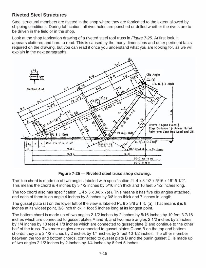
Riveted Steel StructuresSteel structural members are riveted in the shop where they are fabricated to the extent allowed byshipping conditions. During fabrication, all rivet holes are punched or drilled whether the rivets are to be driven in the field or in the shop.Look at the shop fabrication drawing of a riveted steel roof truss in Figure 7-25. At first look, itappears cluttered and hard to read. This is caused by the many dimensions and other pertinent facts required on the drawing, but you can read it once you understand what you are looking for, as we will explain in the next paragraphs.
Figure 7-25 — Riveted steel truss shop drawing.
7-15
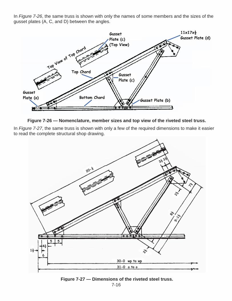
Figure 7-27 — Dimensions of the riveted steel truss.
In Figure 7-26, the same truss is shown with only the names of some members and the sizes of the gusset plates (A, C, and D) between the angles.
In Figure 7-27, the same truss is shown with only a few of the required dimensions to make it easier to read the complete structural shop drawing.
Figure 7-26 — Nomenclature, member sizes and top view of the riveted steel truss.
7-16
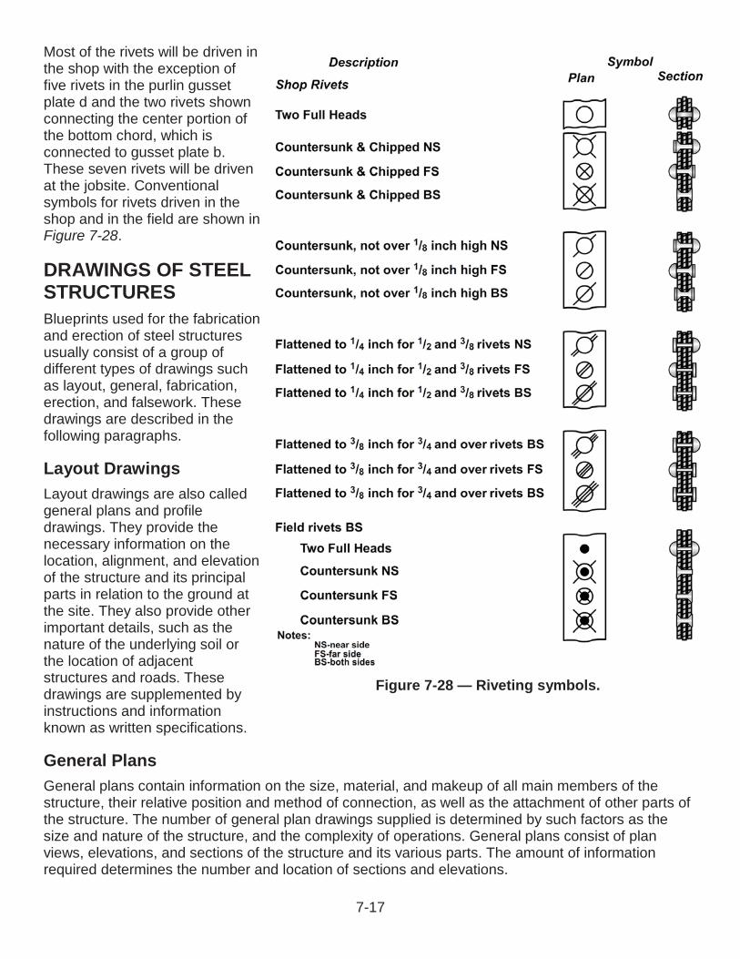
Most of the rivets will be driven in the shop with the exception of five rivets in the purlin gusset plate d and the two rivets shown connecting the center portion of the bottom chord, which is connected to gusset plate b. These seven rivets will be driven at the jobsite. Conventional symbols for rivets driven in the shop and in the field are shown in Figure 7-28.
DRAWINGS OF STEEL STRUCTURESBlueprints used for the fabrication and erection of steel structures usually consist of a group of different types of drawings such as layout, general, fabrication,erection, and falsework. These drawings are described in the following paragraphs.
Layout DrawingsLayout drawings are also called general plans and profile drawings. They provide the necessary information on the location, alignment, and elevation of the structure and its principal parts in relation to the ground at the site. They also provide other important details, such as the nature of the underlying soil or the location of adjacent structures and roads. Thesedrawings are supplemented by instructions and information known as written specifications.
General PlansGeneral plans contain information on the size, material, and makeup of all main members of thestructure, their relative position and method of connection, as well as the attachment of other parts ofthe structure. The number of general plan drawings supplied is determined by such factors as the size and nature of the structure, and the complexity of operations. General plans consist of plan views, elevations, and sections of the structure and its various parts. The amount of information required determines the number and location of sections and elevations.
Figure 7-28 — Riveting symbols.
7-17
Fabrication DrawingsFabrication drawings, or shop drawings, contain necessary information on the size, shape, material, and provisions for connections and attachments for each member. This information is in enough detail to permit ordering the material for the member concerned and its fabrication in the shop or yard. Component parts of the members are shown in the fabrication drawing, as well as dimensions and assembly marks.
Erection DrawingsErection drawings, or erection diagrams, show the location and position of the various members in the finished structure. They are especially useful to personnel performing the erection in the field. Forinstance, the erection drawings supply the approximate weight of heavy pieces, the number of pieces, and other helpful data.
Falsework DrawingsThe term falsework refers to temporary supports of timber or steel required in the erection of difficult or important structures. When falsework is required on an elaborate scale, drawings similar to thegeneral and detail drawings already described may be provided to guide construction. For simple falsework, field sketches may be all that is needed.
CONSTRUCTION PLANSConstruction drawings are those in which as much construction information as possible is presentedgraphically, or by means of pictures (Figure 7-29). Most construction drawings consist of orthographic views. General drawings consist of plans and elevations drawn on relatively small scale. Detail drawings consist of sections and details drawn on a relatively large scale; we will discuss detail drawing in greater depth later in this chapter.
7-18
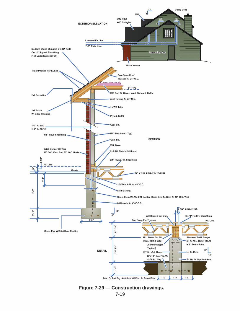
Figure 7-29 — Construction drawings.7-19

Figure 7-30 — Site plan.
General DrawingsGeneral drawings consist of plans (views from above) and elevations (side or front views) drawn on a relatively small scale. Both types of drawings use a standard set of architectural symbols. The most common construction plans are site plans, plot plans, foundation plans, floor plans, and framing plans. We will discuss each of them in the following paragraphs.
Site PlanThe site plan shown in Figure 7-30 shows the contours, boundaries, roads, utilities, trees, structures, and any other significant physical features on or near the construction site. It shows the locations of proposed structures in outline. This plan also shows corner locations relative to reference lines, shown on the plot, which can be located at the site. By showing both existing and finished contours, the site plan furnishes essential data for the graders and excavators.
7-20

Figure 7-31 — Plot plan.
Plot PlansThe plot plan shows the survey marks, including the bench mark (BM), with the elevations and the grading requirements. Surveyors use the plot plan shown in Figure 7-31 to set up the corners and perimeter of the building using batter boards and line stakes. The plot plan furnishes the essential data for laying out the building.
7-21

Foundation PlanA foundation plan is a plane view of a structure. That is, it looks as if it were projected onto a horizontal plane and passed through the structure. In the case of the foundation plan, the plane is slightly below the level of the top of the foundation wall. The plan in Figure 7-32 shows that the main foundation consists of 12 inch and 8 inch concrete masonry unit (CMU) walls measuring 28 feet lengthwise and 22 feet crosswise. The lower portion of each lengthwise section of wall is to be 12 inches thick to provide a concrete ledge 4 inches wide.
A girder running through the center of the building will be supported at the ends by two 4 by 12 inch concrete pilasters butting against the end foundation walls. Intermediate support for the girder will be provided by two 12 by 12 inch concrete piers, each supported on 18 by 18 inch spread footings,which are 10 inches deep. The dotted lines around the foundation walls indicate that these walls will also rest on spread footings.
Floor PlanFloor plans are views of a building as though cutting planes were made through the building horizontally. The cutting plane is generally taken 5 feet 0 inches above the floor being shown.The way a floor plan is developed from elevation, to cutting plane, to floor plan is depicted in Figure 7-33. An architectural or structural floor plan shows the structural characteristics of the building at the level of the plane of projection. A mechanical floor plan shows the plumbing and heating systems and
Figure 7-32 — Foundation plan.
7-22

any other mechanical components other than those that are electrical. An electrical floor plan shows the lighting systems and any other electrical systems.
Framing PlanThe floor framing plan (Figure 7-34) is a plan view of the layout of girders, beams, and joists. Joists and double framing are drawn in the position they will occupy in the completed building. Joists do not need dimensions at every location. Notes provide the necessary information, in this case “2" by 8" joists at 16 inches on center (O.C.).Bridging is also drawn in position perpendicular to the joist but called out by note as “2- 1” x 3” bridging”. The span of the joist controls the number of required rows of cross bridging. The rows should not be more than 7 or 8 feet apart. Hence, a 14 foot span may need only one row of bridging, but a 16 foot span needs two rows. Notes also identify floor openings, trimmers, plates, or doubles to support heavier floor loads.Floor framing plans do not indicate length dimensions for individual pieces. The builder is able to determine those from overall building dimensions, dimensions for each bay, or distances between columns or posts.Wall framing plans (Figure 7-35) show the location and method of framing openings and ceiling heights so that studs and posts can be cut. Since it is a view on a vertical plane, a wall framing plan is
Figure 7-33 — Typical floor plan.
7-23

not a plan in the strict technical sense. However, the practice of calling it a plan has become a general custom.
Roof framing plans for wood frame construction are drawn in the same manner as the floor framing plan. The rafters are shown in the same manner as joists, with rafters shown spanning the building and supporting the roof.A utility plan is a floor plan that shows the layout of heating, electrical, plumbing, or other utility systems. Utility plans are used primarily by the ratings responsible for the utilities, and are equally important to the builder. Most utility installations require that openings be left in walls, floors, and roofs for the admission or installation of utility features. The builder who is placing a concrete foundation wall must study the utility plans to determine the number, sizes, and locations of openings he or she must leave for utilities.
Figure 7-34 — Floor framing plan.
7-24

ElevationsElevations show the front, rear, and sides of a structure, as they would appear projected on vertical planes. Studying the elevation drawing (Figure 7-36) gives you a working idea of the appearance and layout of the structure.
Detail Drawings
Sectional ViewsSectional views, or sections, provide important information about the height, materials, fastening and support systems, and concealed features of a structure. The initial development of a section and how a structure looks when cut vertically by a cutting plane is shown Figure 7-37. The cutting plane is not necessarily continuous, but, as with the horizontal cutting plane in building plans, may be staggered to include as much construction information as possible. Like elevations, sectional views are vertical projections. They are also detail drawings drawn to large scale. This aids in reading, and provides information that cannot be given on elevation or plan views. Sections are classified as typical and specific.
Figure 7-35 — Wall framing plans.
7-25
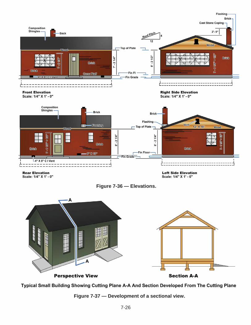
Figure 7-36 — Elevations.
Figure 7-37 — Development of a sectional view.
7-26

Typical sections (Figure 7-38) represent the average condition throughout a structure and are used when construction features are repeated many times. You can see that it gives a great deal of information necessary for those constructing the building.
Section B-B, shown in Figure 7-39 of the foundation plan, shows that both side walls (22 foot measurements) are 8 inches thick centered on a 24 inch concrete footing to an unspecified height. It also illustrates the pilaster, a specific section of the wall to be constructed for support of the girder. It shows that the pilaster is constructed of 12 by 8 by 16 inch CMUs alternated with 4 by 8 by 16 inch and 8 by 8 by 16 inch CMUs. The hidden lines (dashed lines) on the 12 inch wide units indicate that the thickness of the wall beyond the pilaster is 8 inches. Notice how the extra 4 inch thickness of the pilaster provides a center support for the girder, which will support the floor joists.
Detail ViewsDetail views are large-scale drawings of construction assemblies and installations that cannot be clearly shown in the sections. These enlarged drawings show the various parts in more detail and how they will be connected and placed.
Figure 7-38 — Typical section of a masonry building.
Figure 7-39 — Specific section of a concrete masonry wall.
7-27

The scale depends on how large the drawing needs to be magnified to explain the required information clearly. Details are usually drawn at a larger scale than the sections, generally 1-, 1 -,or 3-inch = 1 foot.
Architectural drawing standards contain details commonly used for installation of items such as doorframes, window frames, fireproofing, and material connections; they do, however, need to be adapted to the particular building being drawn. When different conditions actually exist, avoid the use of “typical” details; they will be misleading and cause confusion. The designer needs to understand construction well enough to make accurate detail drawings for each unique situation.Details are commonly used for some specific phases and elements of construction such as foundations, doors, windows, cornices, and so forth (Figure 7-40). Show their details with theapplicable main division of construction drawings and group them so that references can be made easily from the general drawing. Use architectural symbols (Figure 7-41) to provide reference locations for doors and windows in general, sectional, and detail drawings.
7-28

Figure 7-40 — Example of detail grouping.
7-29

Figure 7-41 — Common architectural symbols for doors and windows.
7-30

SpecificationsBecause many aspects of construction cannot be shown graphically, even the best prepared construction drawings often inadequately show some portions of a project. For example, how can anyone show on a drawing the quality of workmanship required for the installation of doors and windows? Or, who is responsible for supplying the materials? These are things that can be conveyed only by hand lettered notes. The standard procedure is to supplement construction drawings with detailed written instructions. These written instructions, called specifications, or more commonly specs, define and limit materials and fabrication to the intent of the engineer or designer.The drawings, together with the project specifications, define the project in detail and show exactly how to construct it. Usually, drawings for an important project are accompanied by a set of project specifications. The drawings and project specifications are inseparable. Drawings indicate what the project specifications do not cover. Project specifications indicate what the drawings do not portray, or they further clarify details that are not covered amply by the drawings and notes on the drawings. When you are preparing project specifications, it is important that you closely coordinate the specifications and drawings in order to minimize discrepancies and ambiguities.When preparing drawings, you will need to be familiar with the general format and terminology used in the specifications. After the last specification, list the definitions of the terms used. Certain routine declarations of responsibility and certain conditions to be maintained on the job may accompany the specifications. A flow chart for selection and documentation of concrete proportions is illustrated in Figure 7-42.
7-31

Figure 7-42 — Flow Chart for selection and documentation of concrete proportions. 7-32

End of Chapter 7
Structural and Architectural DrawingsReview Questions
or aircraft?
A. Isometric viewB. Orthographic projectionC. Pictorial drawingD. Revolved view
7-2. What document provides common symbols used in an architectural drawing?
A. ASME Y41.3.4B. ASTM F3000-1DC. IEEE 101GD. MIL-STD-18B
7-3. Which of the following types of shapes are the most common structural members?
A. A, C, and HB. A, S, and WC. C, H, and JD. C, S, and W
7-4. Which of the following symbols is used to identify wide-flange steel beams?
A. W B. HPC. S D. C
7-5. Which of the following symbols is used to identify a bearing pile?
A. W B. HPC. S D. C
7-6. Which of the following types of angle shapes are most commonly used?
A. Acute and obtuse anglesB. Equal-leg and acute angleC. Equal-leg and unequal-legD. Obtuse and unequal-leg
7-33
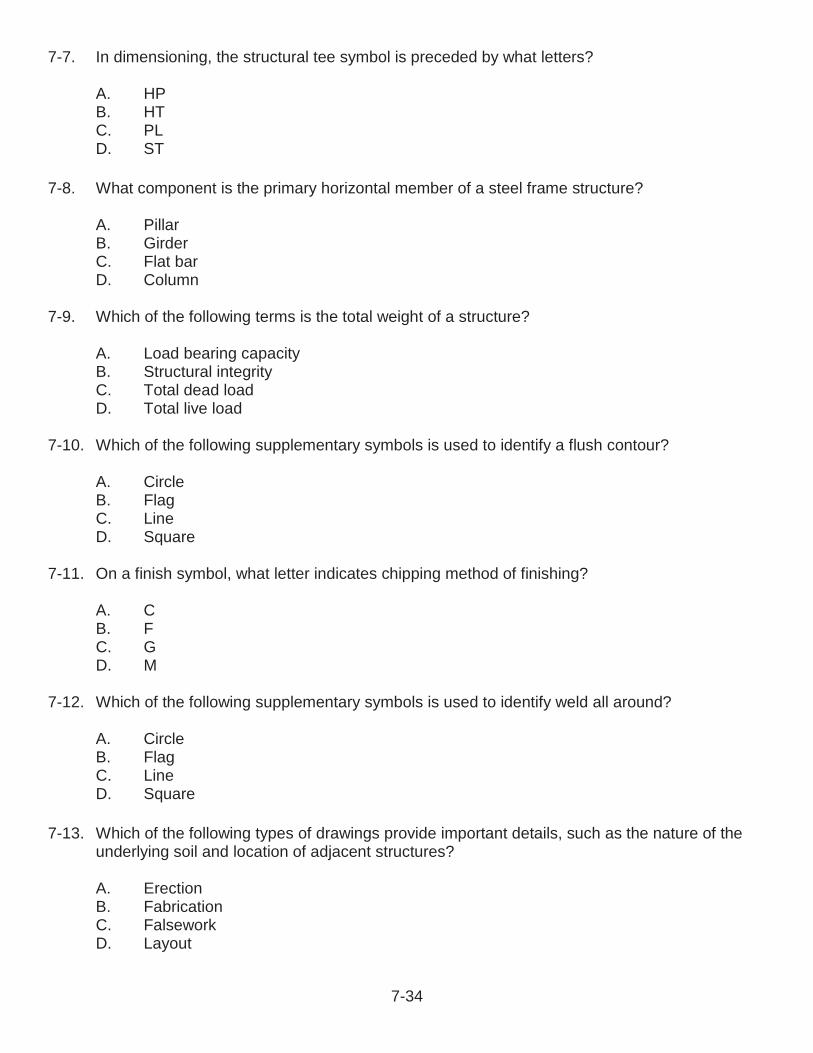
7-7. In dimensioning, the structural tee symbol is preceded by what letters?
A. HPB. HTC. PLD. ST
7-8. What component is the primary horizontal member of a steel frame structure?
A. PillarB. GirderC. Flat barD. Column
7-9. Which of the following terms is the total weight of a structure?
A. Load bearing capacityB. Structural integrityC. Total dead loadD. Total live load
7-10. Which of the following supplementary symbols is used to identify a flush contour?
A. CircleB. FlagC. LineD. Square
7-11. On a finish symbol, what letter indicates chipping method of finishing?
A. CB. FC. GD. M
7-12. Which of the following supplementary symbols is used to identify weld all around?
A. CircleB. FlagC. LineD. Square
7-13. Which of the following types of drawings provide important details, such as the nature of the underlying soil and location of adjacent structures?
A. ErectionB. FabricationC. FalseworkD. Layout
7-34
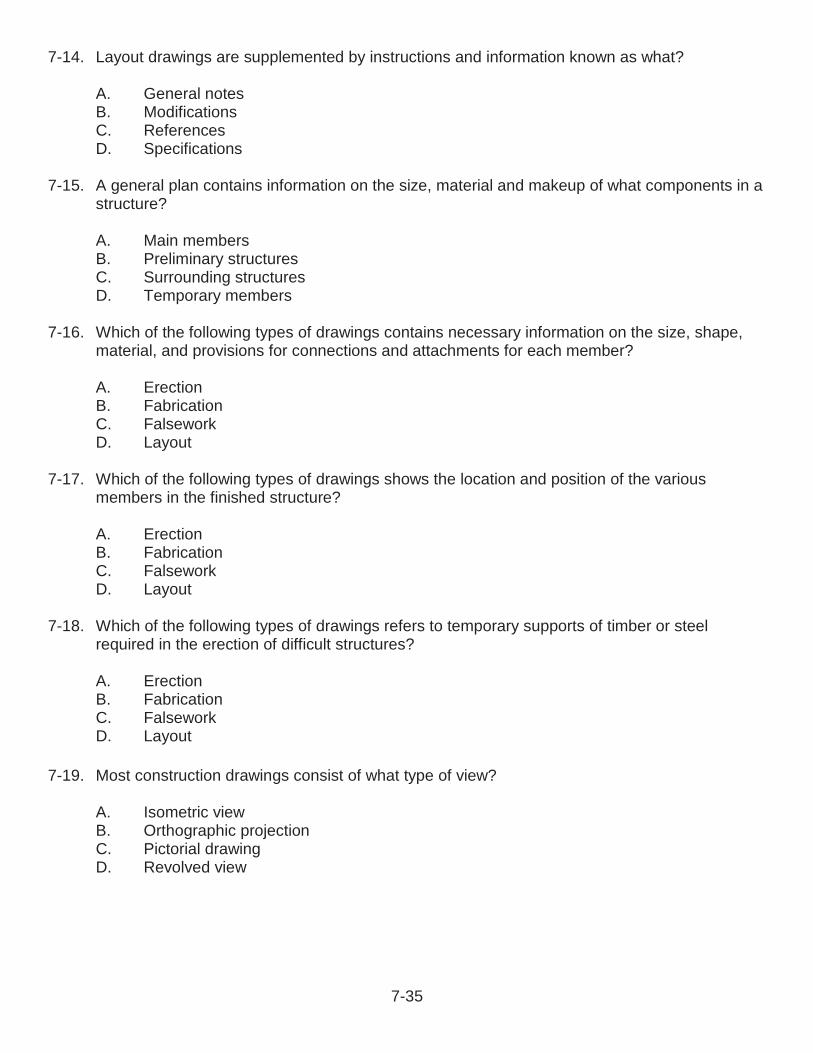
7-14. Layout drawings are supplemented by instructions and information known as what?
A. General notesB. ModificationsC. ReferencesD. Specifications
7-15. A general plan contains information on the size, material and makeup of what components in a structure?
A. Main membersB. Preliminary structuresC. Surrounding structuresD. Temporary members
7-16. Which of the following types of drawings contains necessary information on the size, shape, material, and provisions for connections and attachments for each member?
A. ErectionB. FabricationC. FalseworkD. Layout
7-17. Which of the following types of drawings shows the location and position of the various members in the finished structure?
A. ErectionB. FabricationC. FalseworkD. Layout
7-18. Which of the following types of drawings refers to temporary supports of timber or steel required in the erection of difficult structures?
A. ErectionB. FabricationC. FalseworkD. Layout
7-19. Most construction drawings consist of what type of view?
A. Isometric viewB. Orthographic projectionC. Pictorial drawingD. Revolved view
7-35
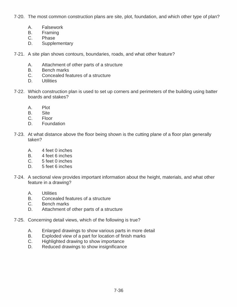
7-20. The most common construction plans are site, plot, foundation, and which other type of plan?
A. FalseworkB. FramingC. PhaseD. Supplementary
7-21. A site plan shows contours, boundaries, roads, and what other feature?
A. Attachment of other parts of a structureB. Bench marksC. Concealed features of a structureD. Utilities
7-22. Which construction plan is used to set up corners and perimeters of the building using batter boards and stakes?
A. PlotB. SiteC. FloorD. Foundation
7-23. At what distance above the floor being shown is the cutting plane of a floor plan generally taken?
A. 4 feet 0 inchesB. 4 feet 6 inchesC. 5 feet 0 inchesD. 5 feet 6 inches
7-24. A sectional view provides important information about the height, materials, and what other feature in a drawing?
A. UtilitiesB. Concealed features of a structureC. Bench marksD. Attachment of other parts of a structure
7-25. Concerning detail views, which of the following is true?
A. Enlarged drawings to show various parts in more detailB. Exploded view of a part for location of finish marksC. Highlighted drawing to show importanceD. Reduced drawings to show insignificance
7-36
RATE TRAINING MANUAL – User UpdateSWOS makes every effort to keep their manuals up-to-date and free of technical errors. We appreciate your help in this process. If you have an idea for improving this manual, or if you find an error, a typographical mistake, or an inaccuracy in SWOS manuals, please write or e-mail us, using this form or a photocopy. Be sure to include the exact chapter number, topic, detailed description, and correction, if applicable. Your input will be brought to the attention of the Technical Review Committee. Thank you for your assistance.Write: SWOS Project Manager
1534 Piersey Street Suite 321Norfolk, VA 23511-2613COMM: (757) 444-5332DSN: 564-5332
E-mail: Refer to the SWOS Norfolk page on the NKO Web page for current contact information.
Rate____ Course Name_____________________________________________
Revision Date__________ Chapter Number____ Page Number(s)____________
Description_____________________________________________________________________________________________________________________________________________________________________________________________
(Optional) Correction_____________________________________________________________________________________________________________________________________________________________________________________________
(Optional) Your Name and Address_____________________________________________________________________________________________________________________________________________________________________________________________
7-37
CHAPTER 8
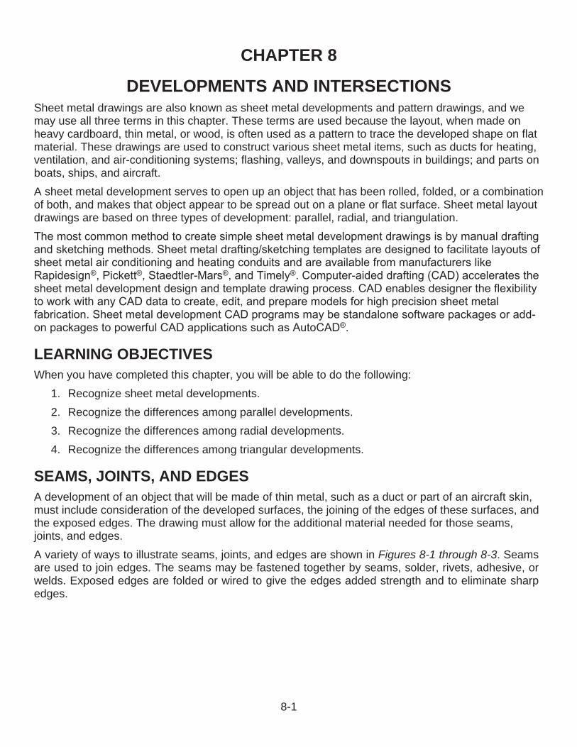
DEVELOPMENTS AND INTERSECTIONSSheet metal drawings are also known as sheet metal developments and pattern drawings, and we may use all three terms in this chapter. These terms are used because the layout, when made on heavy cardboard, thin metal, or wood, is often used as a pattern to trace the developed shape on flat material. These drawings are used to construct various sheet metal items, such as ducts for heating, ventilation, and air-conditioning systems; flashing, valleys, and downspouts in buildings; and parts on boats, ships, and aircraft.A sheet metal development serves to open up an object that has been rolled, folded, or a combination of both, and makes that object appear to be spread out on a plane or flat surface. Sheet metal layout drawings are based on three types of development: parallel, radial, and triangulation.
LEARNING OBJECTIVESWhen you have completed this chapter, you will be able to do the following:
1. Recognize sheet metal developments.2. Recognize the differences among parallel developments.3. Recognize the differences among radial developments.4. Recognize the differences among triangular developments.
SEAMS, JOINTS, AND EDGESA development of an object that will be made of thin metal, such as a duct or part of an aircraft skin, must include consideration of the developed surfaces, the joining of the edges of these surfaces, and the exposed edges. The drawing must allow for the additional material needed for those seams,joints, and edges.A variety of ways to illustrate seams, joints, and edges shown in Figures 8-1 through 8-3. Seams are used to join edges. The seams may be fastened together by seams, solder, rivets, adhesive, or welds. Exposed edges are folded or wired to give the edges added strength and to eliminate sharp edges.
8-1

Figure 8-1 — Seams.
Figure 8-2 — Joints.
Figure 8-3 — Edges.
8-2

There are three types of lap seams: the plain lap seam, the offset lap seam, and the corner lap seam(Figure 8-4). Lap seams can be joined by drilling and riveting, by soldering, or by both riveting and soldering. To figure the allowance for a lap seam, you must first know the diameter of the rivet thatyou plan to use. The center of the rivet must be set in from the edge a distance of 2 times itsdiameter; therefore, the allowance must be 5 times the diameter of the rivet that you are using.
The Pittsburgh lock seam (Figure 8-6) is a corner lock seam. This seam is used as a lengthwise seam at corners of square and rectangular pipes and elbows as well as fittings and ducts.
Figure 8-4 — Lap seams.
Figure 8-5 — Grooved seams.
Figure 8-6 — Pittsburgh lock seam.
8-3

The Pittsburgh lock seam can be made in a brake but it has proved to be so universal in use that special forming machines have been designed and are available. The lock seam appears to be quite complicated, but like lap and grooved seams, it consists of only two pieces. The two parts are the flanged, or single, edge and the pocket that forms the lock. The pocket is formed when the flanged edge is inserted into the pocket, and the extended edge is turned over the inserted edge to complete the lock.Note that most of the sheet metal developments illustrated in this chapter do not make any allowances for edges, joints, or seams. However, the designer who lays out a development must add extra metal where needed.
BENDSThe designer must also show where the material will be bent, and Figure 8-7 shows several methods used to mark bend lines. If the finished part is not shown with the development, then drawing instructions, such as “bend up 90 degrees,” “bend down 180 degrees,” or “bend up 45 degrees,”should be shown beside each bend line.When bending metal to exact dimensions, the amount of material needed to form the bend must be known. The term for the amount of material that is actually used in making the bend is known as bend allowance.
Figure 8-7 — Methods used to identify fold or bend lines.
8-4

Bending compresses the metal on the inside of the bend and stretches the metal on the outside of the bend. Approximately halfway between these two extremes lays a space that neither shrinks nor stretches. This space is known as the neutral line or neutral axis (Figure 8-8). It is along the neutral axis that bend allowance is computed.
Bend Allowance TermsIt is important to be familiar with the following terms related to a bending job. The bend allowance terminology location is illustrated inFigure 8-9.
Bend allowance—is the amount of material consumed in making a bend.
Leg—is the longer part of a formed angle.
Flange—is the shorter part of a formed angle, the opposite of leg. If each side of the angle is the same length, then each is known as a leg.
Flat—is that flat portion not included in the bend. It is equal to the base measurement minus the setback.
Base measurement—is the outside dimension of a formed part. Base measurement will be given on the drawing or blueprint, or it may be obtained from the original part.
Setback (SB)—is the distance from the bend tangent line to the mold point. In a 90-degree bend, SB = R + T (radius of the bend plus thickness of the metal). The setback dimension must be determined prior to making the bend because setback is used to determine the location of the beginning bend tangent line.
Radius (R)—of the bend is always to the inside of the metal being formed unless otherwise stated. The minimum allowable radius for bending a given type and thickness of material should always be determined before proceeding with any bend allowance calculations.
Mold line—is the line formed by extending the outside surfaces of the leg and the flange. (An imaginary point from which real base measurements are provided on drawings.)
Bend tangent line—is the line at which the metal starts to bend and the line at which the metal stops curving. All the space between the bend tangent lines is the bend allowance.
Figure 8-8 — Neutral axis.
Figure 8-9 — Bend allowance terms.
8-5

K number—is one of 179 numbers on the K chart that corresponds to one of the angles between 0 and 180 degrees to which metal can be bent. When metal is to be bent to any angle other than 90 degrees (K number of 1.0), the corresponding K number is selected from the chart and multiplied by the sum of the radius and the thickness of the metal. The product is the amount of setback for the bend.
Closed angle—is less than 90 degrees when measured between legs. When the closed angle is 45 degrees, the amount of bend is 180 minus 45 or 135 degrees.
Open angle—is more than 90 degrees when measured between legs or less than 90 degrees when the amount of bend is measured.
Bend Allowance FormulaBy experimentation with actual bends in metals, aircraft engineers have found that accurate bending results could be obtained by using the following formula for any degree of bend from 1 to 180:(0.0173 x R + 0.0078 x T) x N = BAwhereR = the desired bend radius,T = the thickness of the material, andN = the number of degrees of bend.Refer to the General Manual for Structural Repair, Naval Air Systems Command (NAVAIR) manual 01-1A-1, for the appropriate bend allowance tables.
SHEET METAL SIZESThe thickness of sheet metal is usually specified by the non-linear measure known as its gauge. Thick sheet metal gauge sizes have low gauge numbers, while thinner sheet metal gauge numbers are high. Steel sheet metal sizes from 30 gauge to about 7 gauge are the most commonly used gauges. Gauge differs between iron based metals and non-iron based metals such as copper and aluminum. There are many different metals that can be made into sheet metal, such as aluminum, brass, copper, steel, tin, nickel, and titanium. For decorative uses, important sheet metals include silver, gold, and platinum (platinum sheet metal is also utilized as a catalyst.)Metal thicknesses up to 0.25 inch (6 millimeters) are usually designated by a series of gauge numbers. Metal 0.25 inch and over is given in inch and millimeter sizes. In calling for the material size of sheet metal developments, it is customary to give the gauge number, type of gauge, and its inch or millimeter equivalent in brackets followed by the developed width and length in one sheet metal size(Figure 8-10). A gauge system is used for carbon steels but not appropriate for stainless steels where thickness is specified in decimals. The USS in Figure 8-10 identifies the type of gauge system, in this case the United States Standard gauge system.
Figure 8-10 — Example of a sheet metal size.
8-6

TYPES OF DEVELOPMENTA surface is said to be developable if a thin sheet of flexible material, such as paper, can be wrapped smoothly about its surface. Therefore, objects that have plane, flat, or single-curved surfaces are developable. But a surface that is double-curved or warped is not considered developable, and approximate methods must be used to develop it. Typical sheet metal developments are illustrated in Figure 8-11.A spherical shape would be an example of an approximate development. The material would be stretched to compensate for small inaccuracies. For example, the coverings for a football or basketball are made in segments. Each segment is cut to an approximate developed shape, and the segments are then stretched and sewed together to give the desired shape.The three procedures commonly used in developing patterns are parallel-line, radial-line, and triangular development.
Parallel-Line DevelopmentParallel-line development refers to the development of an object that has surfaces on a flat plane of projection. The true size of each side of the object is known and the sides can be laid out in successive order. The development of a simple rectangular box with a bottom and four sides is illustrated in Figure 8-12. There is an allowance for lap seams at the corners and for a folded edge. The fold lines are shown as thin unbroken lines. Note that all lines for each surface are straight.
Figure 8-11 — Typical sheet metal development.
8-7
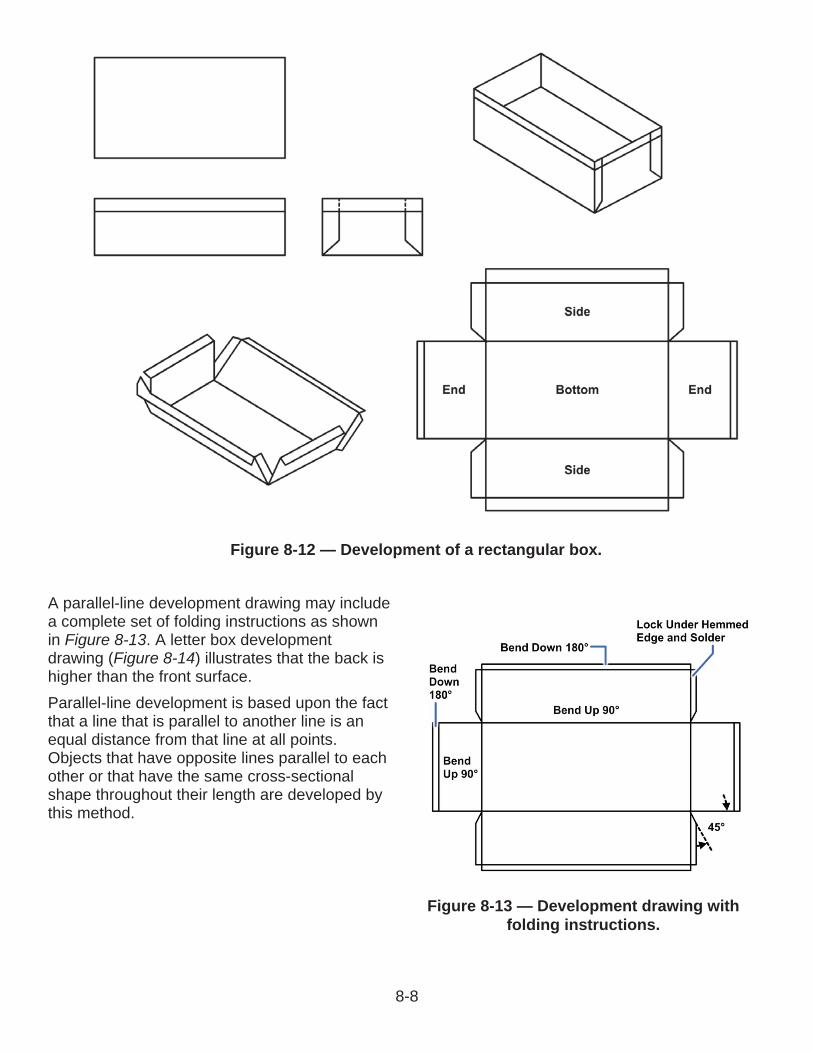
A parallel-line development drawing may include a complete set of folding instructions as shown in Figure 8-13. A letter box development drawing (Figure 8-14) illustrates that the back is higher than the front surface.Parallel-line development is based upon the fact that a line that is parallel to another line is an equal distance from that line at all points. Objects that have opposite lines parallel to each other or that have the same cross-sectional shape throughout their length are developed by this method.
Figure 8-13 — Development drawing with folding instructions.
Figure 8-12 — Development of a rectangular box.
8-8

Truncated CylinderTo gain a clear understanding of the parallel-line method, we will develop a layout of a truncated cylinder (Figure 8-15). Such a piece can be used as one half of a two-piece 90-degree elbow. A truncated cylinder is developed in Figure 8-16:
1. Mark out reference lines using a set square.2. Identify the diameter measurement and draw a circle. Here the
diameter is 1 inches (40 millimeters).3. Use the radius of the circle to divide the circumference into 12
equal sectors.4. Label the marks 1 to 12. Note the numbers begin on the right-hand
side and go in a clockwise direction.5. Identify and mark the height of the cylinder. Here the height is 2
inches (60 millimeters).6. Determine the angle of the top of the cylinder and use a setsquare.
Here the angle is 45 degrees.7. Mark off the radius on both sides of the reference line to construct
the sides of the cylinder. Transfer numbers 1 to 12 from the circle tothe base of the cylinder. Project these points to the top of thecylinder.
8. Calculate the circumference of the cylinder to determine the stretch out length of the pattern.Use the formula C = D. The diameter here is 1 inches (40 millimeters). Mark out thecircumference on the horizontal base line.
Figure 8-14 — Development drawing of a letter box.
Figure 8-15 —Truncated cylinder.
8-9

9. Divide the length of the circumferenceinto 12. Draw a reference line and markon it one-twelfth of the circumference.Use this measurement to set thedividers. Splitting the circumference intohalves and quarters reduces toleranceerror.
10.Use the dividers to mark thecircumference into 12 equal divisions onthe base line. Mark these divisions 1 to12. The final division is numbered 1.Project these divisions upward at 90 degrees.
11.Now develop the stretch out pattern.Transfer the length of the lines on theside view to the corresponding lines onthe stretch out. Draw the top line curveof the pattern freehand, by usingmaterial like packing cord bent to thecurve or by using a flexible curve.
12.This final shape is the stretch out pattern of the cylindrical shape and can be cut to shape touse as a template.
When the development is finished, the machinist will cut out the pattern. It is normal practice in sheet metal work to place the seam on the shortest side. However, in the development of elbows, the practice would result in considerable waste of material, as shown in Figure 8-17, view A. To avoid thewaste and to simplify cutting the pieces, the seams are alternately placed 180 degrees apart, as shown in Figure 8-17, view B for a two-piece elbow, and view C for a three-piece elbow.
Figure 8-17 — Location of seams on elbows.
Figure 8-16 — Truncated cylinder development.
8-10

Radial-Line DevelopmentIn radial-line development, the slanting lines of pyramids and cones do not always appear in their true lengths in an orthographic view; the designer must find other means to depict them.The radial-line method is similar in some respects to the parallel-line method. Evenly spaced reference lines are necessary in both of these methods. However, in parallel-line development, the reference lines are parallel—like a picket fence. In radial-line development, the reference lines radiate from the apex of a cone—like the spokes of a wheel.The reference lines in parallel-line development project horizontally. In radial-line development, the reference lines are transferred from the front view to the development with the dividers.
The procedure for developing a frustum of a right cone is given below. Check each step of the procedure against the development shown in Figure 8-18.
1. First establish the apex point (H).2. Draw reference lines using a set square. Mark out the measurements of the:
a. Base (D) – 2 inches (70 millimeters).b. Apex (H) – 4 inches (100 millimeters).c. Frustum height (h) – 2 inches (50 millimeters).
3. Draw in the reference lines from the apex (H) to the base (D). Check that the frustum diameter(d) is 1 inches (35 millimeters).
4. Develop the half circle representing half the bottom view.5. Set the dividers at 1 inches (35 millimeters) - the radius of the base of the frustum (D).
Divide the half circle into 6 equal sectors.6. Label the marks 1 to 12 as indicated.7. Project each of the sectors up to the base line at 90 degrees. Project these lines to the apex.8. Develop the stretch out pattern of the frustum. Place the compass point on the apex. Set the
radius to A and swing an arc as indicated. Repeat with the radius set to B.9. Draw a line from the apex to the bottom circumference, away from the base of the frustum.
The intersection point will be the start for marking out the base circumference into 12 sectors.
8-11
Figure 8-1 — .
10.
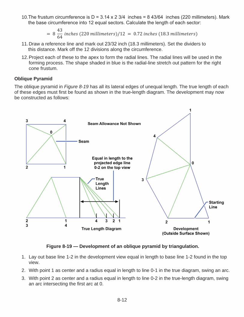
= 8 4364 (220 )/12 = 0.72 (18.3 ) 11.Draw a reference line and mark out inch (18.3 millimeters). Set the dividers to
this distance. Mark off the 12 divisions along the circumference.12.Project each of these to the apex to form the radial lines. The radial lines will be used in the
forming process. The shape shaded in blue is the radial-line stretch out pattern for the rightcone frustum.
Oblique PyramidThe oblique pyramid in Figure 8-19 has all its lateral edges of unequal length. The true length of eachof these edges must first be found as shown in the true length diagram. The development may now be constructed as follows:
1. Lay out base line 1-2 in the development view equal in length to base line 1-2 found in the topview.
2. With point 1 as center and a radius equal in length to line 0-1 in the true diagram, swing an arc.3. With point 2 as center and a radius equal in length to line 0-2 in the true-length diagram, swing
an arc intersecting the first arc at 0.
Figure 8-19 — Development of an oblique pyramid by triangulation.
8-12
4. With point 0 as center and a radius equal in length to line 0-3 in the true-length diagram, swingan arc.
5. With point 2 as center and radius equal in length to base line 2-3 found in the top view, swingan arc intersecting the first arc at point 3.
6. Locate points 4 and 1 in a similar manner, and join those points, as shown, with straight lines.The base and seam lines have been omitted on the development drawing.
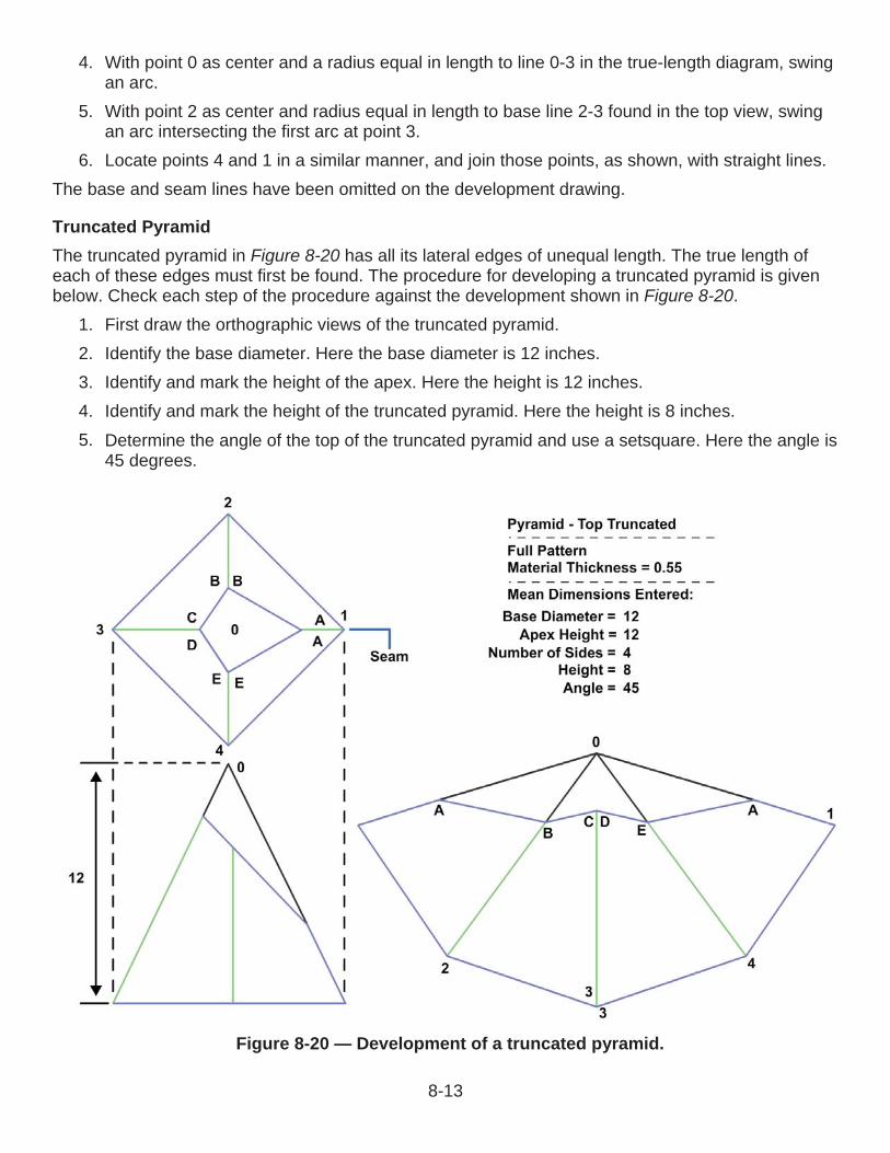
Truncated PyramidThe truncated pyramid in Figure 8-20 has all its lateral edges of unequal length. The true length of each of these edges must first be found. The procedure for developing a truncated pyramid is given below. Check each step of the procedure against the development shown in Figure 8-20.
1. First draw the orthographic views of the truncated pyramid.2. Identify the base diameter. Here the base diameter is 12 inches.3. Identify and mark the height of the apex. Here the height is 12 inches.4. Identify and mark the height of the truncated pyramid. Here the height is 8 inches.5. Determine the angle of the top of the truncated pyramid and use a setsquare. Here the angle is
45 degrees.
Figure 8-20 — Development of a truncated pyramid.
8-13

6. Mark off the radius on both sides of the reference line to construct the sides of the truncatedpyramid.
7. The intersecting points establish the true length of all segments.8. Now develop the stretch out pattern. Transfer the length of the lines on the side view to the
corresponding lines on the stretch out view.9. The final shape is the stretch out pattern of the cylindrical shape and can be cut to shape to
use as a template.
Triangular DevelopmentTriangulation is slower and more difficult than parallel-line or radial-line development, but it is more practical for many types of figures. Additionally, it is the only method by which the development ofwarped surfaces may be estimated. In development by triangulation, the piece is divided into a seriesof triangles, as in radial-line development. However, there is no one single apex for the triangles. The problem becomes one of finding the true lengths of the varying oblique lines. Drawing a true lengthdiagram solves the problem.An example of a layout using triangulation is the development of a transition piece (Figure 8-21).Transition pieces are usually made to connect two different shapes of pipes, such as square to round, rectangular to round, and hexagonal to round. Transition pieces can be used to form parallel and oblique joints where the piping may not be perpendicular to the pipe axis. These transition pieces will usually fit the definition of a non-developable surface that must be developed by approximation.
Oblique ConeAn oblique cone is generally developed by the triangulation method.The base of the cone is divided into an equal number of divisions. The elements 0-1, 0-2, and so on are drawn in the top view, projected down, and drawn in the front view. The true lengths of the elements are not shown in either the top or front view, but would be equal in length to the hypotenuse of a right triangle, having one leg equal in length to the projected element in the top view and the other leg equal to the height of the projected element in the front view. When it is necessary to find the true length of a number of edges, or elements, then a true-length diagram can be drawn adjacent to the front view, preventing the front view from being cluttered with lines.
Figure 8-21 — Transition pieces.
8-14

Since the development of the oblique cone (Figure 8-22) will be symmetrical, the starting line will be element 0-13. The development is constructed as follows:
1. With 0 as center and the radius equal to the true length of element 0-12, draw an arc.2. With 13 as center and the radius equal to distance 12-13 in the top view, draw a second arc
intersecting the first point at 12. Draw element 0-12 on the development.3. With 0 as center and the radius equal to the true length of element 0-11, draw an arc. With 11
as center and the radius equal to distance 11-12 in the top view, draw a second arcintersecting the first point at 11. Draw element 0-11 on the development.
4. Repeat these steps with the remaining elements until all element lines are located on thedevelopment view.
Square-to-RoundThe steps in the triangulation of a warped transition piece joining a large, square duct and a small, round duct are shown in Figure 8-23. The steps are as follows:
1. First establish the reference lines.2. Develop the top view. With a set square, mark out the measurements for half the base, and
label each corner (from the top left-hand corner, moving clockwise) A to D.3. From the center of the half base, draw a semicircle with radius 1 inch (25 millimeter). Check
that the diameter (D) is 2 inches (50 millimeters).
Figure 8-22 — Development of an oblique cone.
8-15

4. Divide the half circle into six equal spaces by placing the compass point on the three pointswhere the semicircle intersects the reference lines and swinging small arcs (R = 1 inch (25millimeter)) to intersect the circle. Number the points 1 to 7 as shown.
5. Using a set square, draw lines from point D on the base of the shape to points 1 through to 4on the half circle. Next, draw lines from C on the base of the shape to points 4 through to 7,which completes (half) the top view.
6. Draw the side view. First, draw a reference line. Remember, the vertical height is 50millimeters, and the diameter of the top is 50 millimeters.
7. The base is 2 inches (70 millimeters) square. Draw lines from the base to the top. Label the base points A and B. Label the top points 1 and 7.
8. Now develop the stretch out pattern for the square-to-round. First establish a reference line(extending to the right from point B on the side view) for the base of the stretch out pattern.Draw the vertical height of the square-to-round somewhere to the right of the side view,perpendicular to the base line.a. Now place the compass point on D in the top view. Set the radius to point 2 on the half
circle. Place the compass point at the intersection of the base line and the vertical heightline and swing an arc to mark the base line. Label this point 2D. Note this point is theshortest distance from point D to the top of the half circle, the same length as 3D, 5C, and6C.
b. Now place the compass at D and set the radius to point 1 on the half circle. Transfer thecompass to the intersection of the base line and the vertical height line and swing an arc tomark the base line. Label the point 1D. Note this point is the longer distance from point D tothe top of the half diameter, the same length as 4D, 4C, and 7C.
c. Now draw a line from the top of the vertical height line to point 2D, and then from the top topoint 1D. This diagram is called the true length diagram.
Figure 8-23 — Triangular development of a transition piece.
8-16
9. Mark a point on the base line to the right of point 1D.10.Set the compass at the distance between D and C on the top view (the true length), then
transfer the distance D to C to the base line. Label the points D and C. Reset the compass tothe length of the line 4D. Placing one point on D, draw an arc midway between D and C. Shiftthe compass to C, draw an arc to bisect the previous one. Label this point 4.
11.Mark out a new short reference line for one-twelfth of the circumference of the top of thesquare-to-round shape. Calculate the circumference of the top of the shape, and then divide itby 12.C = DC = 3.14 x 2 inches (50 millimeters)= 6 inches (157 millimeters)One-twelfth of the circle= 6 inches (157 millimeters) ÷ 12= inch (13 millimeters)
12.Measure and mark out inch (13 millimeters) on the reference line. Set the compass atinch (13 millimeters) (one-twelfth circumference).a. Place the compass on point 4, and swing arcs to mark to the right and to the left. Set the
compass at the true length of reference line 2D. Place the compass on point D, and swingan arc to intersect the arc on the left. Label this point 3. Place the compass on C, andswing an arc to intersect the arc on the right. Label this point 5.
b. Reset the compass at inch (13 millimeters), using the measure on the reference line.Place the compass on point 5 and swing an arc to the right hand side. Swing an arc to theleft of point 3.
c. Reset the compass at the length of the reference line 2D. Place the compass on point D,make a mark intersecting the arc, and label this point 2. Place the compass on C, make amark intersecting the arc, and label this point 6.
d. Repeat the process, swinging an arc R13 to the left of 2 and right of 6. This time, however,reset the compass to the length of reference line 1D. Place the compass point on D, makea mark intersecting the arc, and label this point 1. Place the compass on C and make amark intersecting the arc. Label this point 7.
13.Develop the half square base from point D to point A.a. Using the side view diagram, set the compass at the distance between B and 7. Place the
compass at point 1 on the stretch out pattern, and draw an arc to the lower left. Repeat theprocess from point 7 to the lower right.
b. Reset the compass to the distance between B and C on the top view diagram. Place thecompass on D and make a mark intersecting the arc. Label this point A. Place the compasson C, make a mark intersecting the arc, and label this point B.
c. Using a set square or ruler, draw lines joining 1 and A; A and D; 7 and B; and B and C.Draw lines from D to 1, 2, 3, and 4. Draw lines from C to 4, 5, 6, and 7.
14.Use a flexible ruler, or freehand to join points 1 to 7.This completes the stretch out half pattern for a square-to-round shape, using the triangulation method. This development does not show a seam allowance.
8-17

Rectangular-to-RoundThe transition piece shown in Figure 8-24 is constructed in the same manner as the square-to-roundexcept that all the elements are of different lengths. To avoid confusion, four true-length diagrams are drawn and the true-length lines are clearly labeled.
Figure 8-24 — Development of an offset transition piece—rectangular to round.
8-18

Hexagon-to-RoundThe transition piece shown in Figure 8-25 is constructed in the same manner as the square-to-round and the rectangular-to-round transition pieces, as all of the elements are, once again, different lengths.
Figure 8-25 — Development of a transition piece—hexagon to round.
8-19
End of Chapter 8
Developments and IntersectionsReview Questions
additional material?
A. Compression during shapingB. Damage to the materialC. Joining of edgesD. Miscalculations
8-2. When drawing a lap seam, the allowance must be how many times the diameter of the rivet being used?
A. 1 B. 3 C. 5 D. 7
8-3. If the finished part is not shown with the development, what item should be included?
A. A scale modelB. Drawing instructionsC. Color code listD. Marking instructions
8-4. Which of the following terms describes the amount of material consumed in making a bend?
A. Base measurementB. Bend allowanceC. Bend tangent lineD. Setback
8-5. The three procedures commonly used in developing patterns are parallel-line, radial-line, and what other type of development?
A. CircularB. PerspectiveC. RectangularD. Triangular
8-6. Which of the following statements defines parallel-line development?
A. The development of an object that has surfaces on a flat plane of projectionB. The development of an object that has surfaces on a slanting plane of projectionC. The first series of prints used in construction and manufacturingD. The perspective print of the development of parallel roadways
8-20

8-7. The parallel-line development is based upon which of the following principles?
A. A line parallel to another line is an equal distance from that line at all pointsB. A line perpendicular to another line will intersect at only one pointC. The lines radiate from the apex of a coneD. When finished, the lines form a three-dimensional drawing
8-8. What type of development is used when an object has the same cross-sectional shape throughout the length?
A. Orthographic-perspectiveB. Parallel-lineC. Radial-lineD. Triangular
8-9. Which of the following shapes is an exception to the normal practice of placing seams on the shortest side in sheet metal development?
A. ConeB. CylinderC. ElbowD. Pyramid
8-10. In what type of development do the slanting lines of pyramids and cones not always appear in the true lengths?
A. Orthographic-perspectiveB. Parallel-lineC. Radial-lineD. Triangular
8-11. Concerning radial-line developments, which of the following statements is true?
A. A line parallel to another line is an equal distance from that line at all pointsB. A line perpendicular to another line will intersect at only one pointC. The lines radiate from the apex of a coneD. When finished, the lines form a three-dimensional drawing
8-12. In a radial-line development, the reference lines are transferred from what view to the development?
A. FrontB. RearC. SideD. Top
8-21

8-13. In a radial-line development of an oblique pyramid, what measurement must be found first?
A. Apex heightB. BaseC. Frustum heightD. Lateral edges
8-14. What type of development is slow and difficult to draw?
A. Orthographic-perspectiveB. Parallel-lineC. Radial-lineD. Triangular
8-15. When using triangular development, to find the true length of the varying oblique lines, what type of diagram is drawn?
A. BlockB. True lengthC. ReferenceD. Architect scale
8-16. Which of the following items is an example of using triangular development?
A. Rectangular boxB. Straight connectionsC. Transition piecesD. Truncated pyramid
8-17. In drawing an oblique cone, the elements are first drawn in which of the following views?
A. FrontB. RearC. SideD. Top
8-18. Which of the following is the first step in developing a square-to-round transition piece?
A.B.C.D.
Establish reference lines Create a true length diagram Develop the top view Draw a semicircle
8-22

RATE TRAINING MANUAL – User UpdateSWOS makes every effort to keep their manuals up-to-date and free of technical errors. We appreciate your help in this process. If you have an idea for improving this manual, or if you find an error, a typographical mistake, or an inaccuracy in SWOS manuals, please write or e-mail us, using this form or a photocopy. Be sure to include the exact chapter number, topic, detailed description, and correction, if applicable. Your input will be brought to the attention of the Technical Review Committee. Thank you for your assistance.Write: SWOS Project Manager
1534 Piersey Street Suite 321Norfolk, VA 23511-2613COMM: (757) 444-5332DSN: 564-5332
E-mail: Refer to the SWOS Norfolk page on the NKO Web page for current contact information.
Rate____ Course Name_____________________________________________
Revision Date__________ Chapter Number____ Page Number(s)____________
Description _____________________________________________________________________________________________________________________________________________________________________________________________
(Optional) Correction _____________________________________________________________________________________________________________________________________________________________________________________________
(Optional) Your Name and Address _____________________________________________________________________________________________________________________________________________________________________________________________
8-23

Index-1
INDEX Addendum, 4-7 Addendum circle, 4-8 Adjustable triangles, 2-6 Aligned section, 3-18 Aircraft electrical prints, 6-9
wire and cable identification, 6-10 Aircraft electronics prints, 6-19
electromechanical drawings, 6-21 wiring diagrams, 6-20
Aircraft wire and cable identification, 6-10 Alternate position of isometric axis, 3-10 Angles in isometric projection, 3-8 Angles, 7-3 Application block, 1-6 Architectural and structural steel drawings, 7-1
construction plans, 7-18 drawings of steel structures, 7-17 structural shapes and members, 7-1 welded and riveted steel structures, 7-9
Auxiliary view, 3-13 Axis, 4-6 Base measurement, 8-5 Basic logic diagrams, 6-24 Beam compass, 2-10 Bearing pile, 7-2 Bend allowance terms, 8-5
base measurement, 8-5 bend allowance, 8-5 bend tangent line, 8-5 closed angle, 8-6 flange, 8-5 flat, 8-5 K number, 8-6 leg, 8-5 mold line, 8-5 open angle, 8-6 radius, 8-5 setback, 8-5
Bend allowance, 8-5 Bends, 8-4
bend allowance formula, 8-6 bend allowance terms, 8-5
Bend tangent line, 8-5 Bill of material, 1-5 Block diagram, 6-1, 6-6, 6-12 Blueprint numbering plan, 1-10 Blueprint parts, 1-2

Index-2
application block, 1-6 bill of material, 1-5 drawing number, 1-3 finish marks, 1-7 information blocks, 1-2 legends and symbols, 1-8 notes and specifications, 1-7 production, 1-1 reference number, 1-3 revision block, 1-3 scale block, 1-4 station number, 1-4 title block, 1-2 zone number, 1-4
Blueprints, 1-1 filing and handling, 1-11 meaning of lines, 1-8 numbering plan, 1-10 parts, 1-2 production, 1-1 shipboard blueprints, 1-10 standards, 1-2
Break lines, 2-16 Broken-out section, 3-18 Cable marking, 6-3
new tag system, 6-4 old tag system, 6-3
Center lines, 2-13 Channels, 7-3 Chordal pitch, 4-8 Circles in isometric projection, 3-9 Circular pitch, 4-8 Clearance, 4-8 Closed angle, 8-6 Columns, 7-4 Common terms and symbols, 4-1
general terminology, 4-1 Compasses, 2-8 Computer-aided design/computer-aided manufacturing, 2-21 Computer-aided drafting (CAD), 2-19
digitizer, 2-20 generating drawings, 2-20 plotter, 2-20 printer, 2-21
Computer logic, 6-21 Computer numerical control, 2-21 Construction lines, 2-13 Construction plans, 7-18
detail drawings, 7-25 general drawings, 7-20 specifications, 7-31

Index-3
Connections, piping, 5-4 Connection diagram, 6-7 Crest, 4-6 Crossings, piping, 5-3 C-shape, 7-3 Datum lines, 2-17 Dedendum, 4-8 Depth, 4-7 Detail drawings, 3-19, 7-25
detail views, 7-27 sectional views, 7-25
Detail view, 7-27 Detailed logic diagrams, 6-24 Development, types of, 8-7
parallel-line development, 8-7 radial-line development, 8-11 triangular development, 8-14
Developments and intersections, 8-1 bends, 8-4 seams, joints, and edges, 8-1 sheet-metal sizes, 8-5 types of development, 8-7
Diagonal hatching in isometric projection, 3-10 Diametral pitch, 4-7 Digitizer, 2-20 Dimension lines, 2-15 Dimensioning, 7-13 Dimetric projections, 3-10 Dividers, 2-8 Drafting tables with boards, 2-4 Drawing aids, 2-4
adjustable triangles, 2-6 beam compass, 2-10 compasses, 2-8 dividers, 2-8 drafting tables with boards, 2-4 drop bow pen, 2-9 French curves, 2-7 instrument sets, 2-7 proportional dividers, 2-10 protractors, 2-6 triangles, 2-5 T-squares, 2-5
Drawing instrument sets, 2-7 compasses, 2-8 dividers, 2-8 drop bow pen, 2-9 maintenance of compasses and dividers, 2-9 beam compass, 2-10 proportional dividers, 2-10
Drawings of steel structures, 7-17