Figure 14.1 The action of a filter on an input signalresults in an output signal.
50
Copyright ©2011, ©2008, ©2005 by Pearson Education, Inc. Upper Saddle River, New Jersey 07458 All rights reserved. Electric Circuits, Ninth Edition James W. Nilsson • Susan A. Riedel Figure 14.1 The action of a filter on an input signalresults in an output signal.
-
Upload
aubrey-durham -
Category
Documents
-
view
22 -
download
0
description
Figure 14.1 The action of a filter on an input signalresults in an output signal. Figure 14.2 A circuit with voltage input and output. - PowerPoint PPT Presentation
Transcript of Figure 14.1 The action of a filter on an input signalresults in an output signal.
Copyright ©2011, ©2008, ©2005 by Pearson Education, Inc.Upper Saddle River, New Jersey 07458
All rights reserved.
Electric Circuits, Ninth EditionJames W. Nilsson • Susan A. Riedel
Figure 14.1 The action of a filter on an input signalresults in an output signal.
Copyright ©2011, ©2008, ©2005 by Pearson Education, Inc.Upper Saddle River, New Jersey 07458
All rights reserved.
Electric Circuits, Ninth EditionJames W. Nilsson • Susan A. Riedel
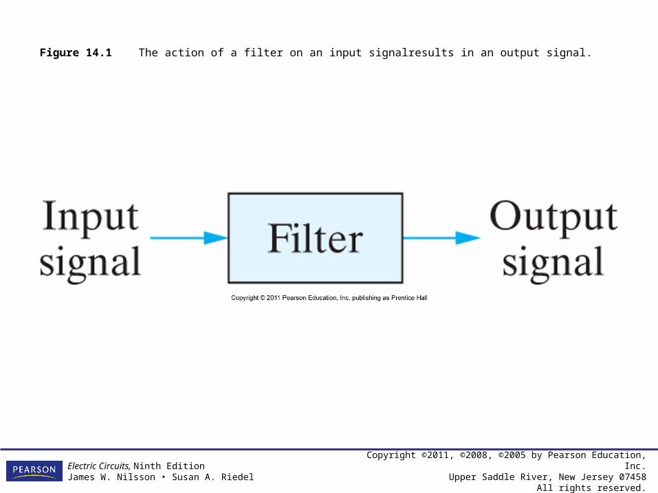
Figure 14.2 A circuit with voltage input and output.

Copyright ©2011, ©2008, ©2005 by Pearson Education, Inc.Upper Saddle River, New Jersey 07458
All rights reserved.
Electric Circuits, Ninth EditionJames W. Nilsson • Susan A. Riedel
Figure 14.3 Ideal frequency response plots of the four types of filter circuits. (a) An ideal low-pass filter. (b) An ideal high-pass filter. (c) An ideal bandpass filter. (d) An ideal bandreject filter.

Copyright ©2011, ©2008, ©2005 by Pearson Education, Inc.Upper Saddle River, New Jersey 07458
All rights reserved.
Electric Circuits, Ninth EditionJames W. Nilsson • Susan A. Riedel
Figure 14.4 (a) A series RL low-pass filter. (b) The equivalent circuit at = 0 and (c) The equivalent circuit at = .

Copyright ©2011, ©2008, ©2005 by Pearson Education, Inc.Upper Saddle River, New Jersey 07458
All rights reserved.
Electric Circuits, Ninth EditionJames W. Nilsson • Susan A. Riedel
Figure 14.5 The frequency response plot for the series RL circuit in Fig. 14.4(a).
Copyright ©2011, ©2008, ©2005 by Pearson Education, Inc.Upper Saddle River, New Jersey 07458
All rights reserved.
Electric Circuits, Ninth EditionJames W. Nilsson • Susan A. Riedel
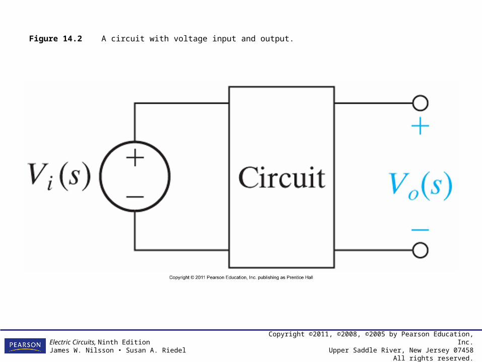
Figure 14.6 The s-domain equivalent for the circuit in Fig. 14.4(a).

Copyright ©2011, ©2008, ©2005 by Pearson Education, Inc.Upper Saddle River, New Jersey 07458
All rights reserved.
Electric Circuits, Ninth EditionJames W. Nilsson • Susan A. Riedel

Copyright ©2011, ©2008, ©2005 by Pearson Education, Inc.Upper Saddle River, New Jersey 07458
All rights reserved.
Electric Circuits, Ninth EditionJames W. Nilsson • Susan A. Riedel
Figure 14.7 A series RC low-pass filter.
Copyright ©2011, ©2008, ©2005 by Pearson Education, Inc.Upper Saddle River, New Jersey 07458
All rights reserved.
Electric Circuits, Ninth EditionJames W. Nilsson • Susan A. Riedel
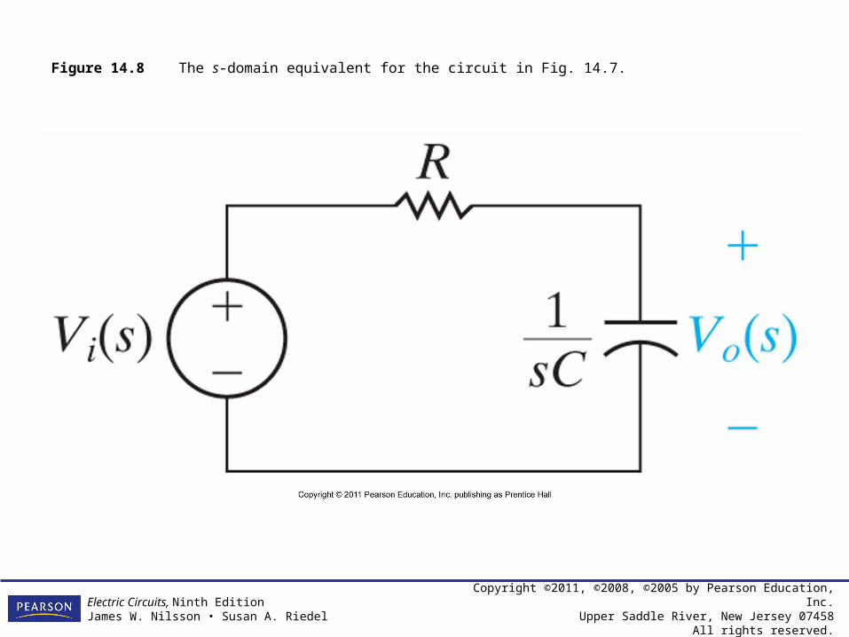
Figure 14.8 The s-domain equivalent for the circuit in Fig. 14.7.
Copyright ©2011, ©2008, ©2005 by Pearson Education, Inc.Upper Saddle River, New Jersey 07458
All rights reserved.
Electric Circuits, Ninth EditionJames W. Nilsson • Susan A. Riedel
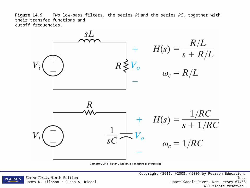
Figure 14.9 Two low-pass filters, the series RL and the series RC, together with their transfer functions and cutoff frequencies.

Copyright ©2011, ©2008, ©2005 by Pearson Education, Inc.Upper Saddle River, New Jersey 07458
All rights reserved.
Electric Circuits, Ninth EditionJames W. Nilsson • Susan A. Riedel
Figure 14.10 A series RC high-pass filter; (b) the equivalent circuit at = 0; and (c) the equivalent circuit at = .
Copyright ©2011, ©2008, ©2005 by Pearson Education, Inc.Upper Saddle River, New Jersey 07458
All rights reserved.
Electric Circuits, Ninth EditionJames W. Nilsson • Susan A. Riedel
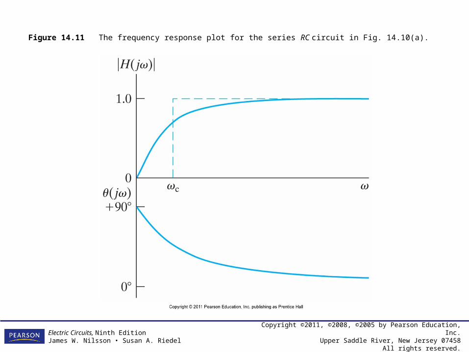
Figure 14.11 The frequency response plot for the series RC circuit in Fig. 14.10(a).

Copyright ©2011, ©2008, ©2005 by Pearson Education, Inc.Upper Saddle River, New Jersey 07458
All rights reserved.
Electric Circuits, Ninth EditionJames W. Nilsson • Susan A. Riedel
Figure 14.12 The s-domain equivalent of the circuit in Fig. 14.10(a).

Copyright ©2011, ©2008, ©2005 by Pearson Education, Inc.Upper Saddle River, New Jersey 07458
All rights reserved.
Electric Circuits, Ninth EditionJames W. Nilsson • Susan A. Riedel
Figure 14.13 The circuit for Example 14.3.
Copyright ©2011, ©2008, ©2005 by Pearson Education, Inc.Upper Saddle River, New Jersey 07458
All rights reserved.
Electric Circuits, Ninth EditionJames W. Nilsson • Susan A. Riedel
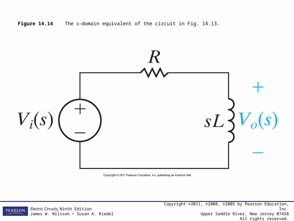
Figure 14.14 The s-domain equivalent of the circuit in Fig. 14.13.

Copyright ©2011, ©2008, ©2005 by Pearson Education, Inc.Upper Saddle River, New Jersey 07458
All rights reserved.
Electric Circuits, Ninth EditionJames W. Nilsson • Susan A. Riedel
Figure 14.15 The circuit for Example 14.4.
Copyright ©2011, ©2008, ©2005 by Pearson Education, Inc.Upper Saddle River, New Jersey 07458
All rights reserved.
Electric Circuits, Ninth EditionJames W. Nilsson • Susan A. Riedel
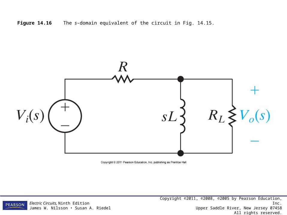
Figure 14.16 The s-domain equivalent of the circuit in Fig. 14.15.
Copyright ©2011, ©2008, ©2005 by Pearson Education, Inc.Upper Saddle River, New Jersey 07458
All rights reserved.
Electric Circuits, Ninth EditionJames W. Nilsson • Susan A. Riedel
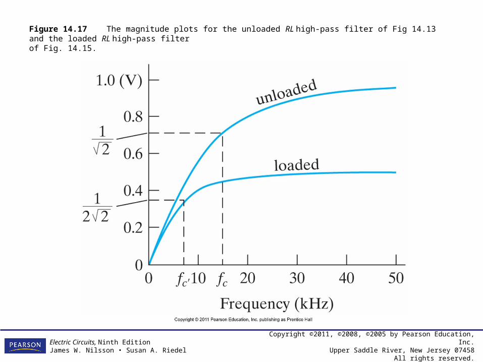
Figure 14.17 The magnitude plots for the unloaded RL high-pass filter of Fig 14.13 and the loaded RL high-pass filterof Fig. 14.15.
Copyright ©2011, ©2008, ©2005 by Pearson Education, Inc.Upper Saddle River, New Jersey 07458
All rights reserved.
Electric Circuits, Ninth EditionJames W. Nilsson • Susan A. Riedel
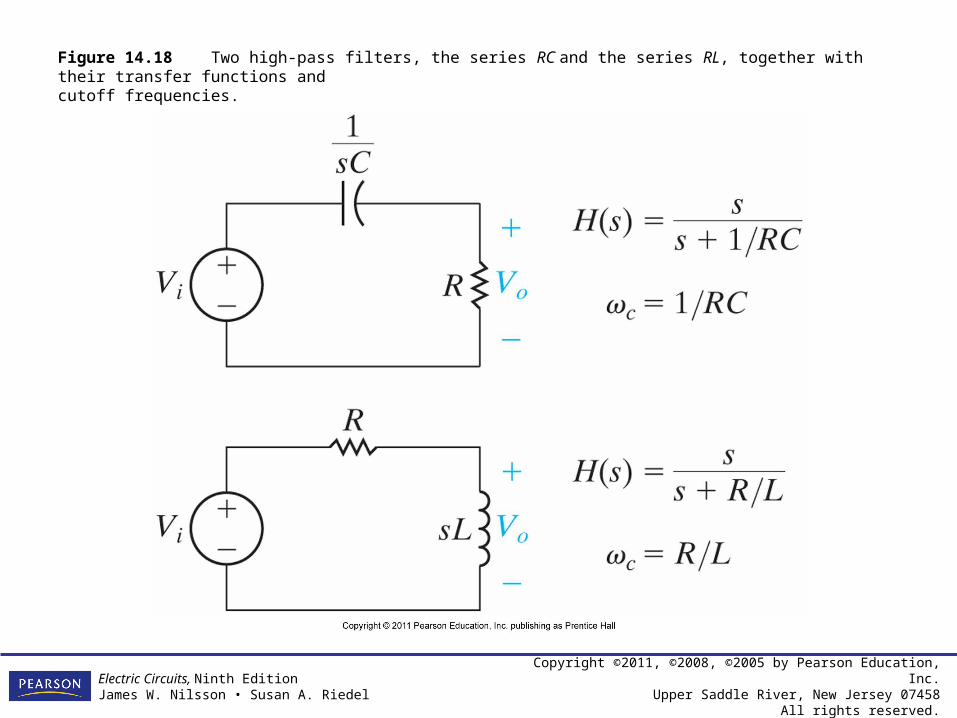
Figure 14.18 Two high-pass filters, the series RC and the series RL, together with their transfer functions andcutoff frequencies.

Copyright ©2011, ©2008, ©2005 by Pearson Education, Inc.Upper Saddle River, New Jersey 07458
All rights reserved.
Electric Circuits, Ninth EditionJames W. Nilsson • Susan A. Riedel
Figure 14.19 (a) A series RLC bandpass filter; (b) theequivalent circuit for = o ; and (c) the equivalentcircuit for = .

Copyright ©2011, ©2008, ©2005 by Pearson Education, Inc.Upper Saddle River, New Jersey 07458
All rights reserved.
Electric Circuits, Ninth EditionJames W. Nilsson • Susan A. Riedel
Figure 14.20 The frequency response plot for the\series RLC bandpass filter circuit in Fig. 14.19.
Copyright ©2011, ©2008, ©2005 by Pearson Education, Inc.Upper Saddle River, New Jersey 07458
All rights reserved.
Electric Circuits, Ninth EditionJames W. Nilsson • Susan A. Riedel
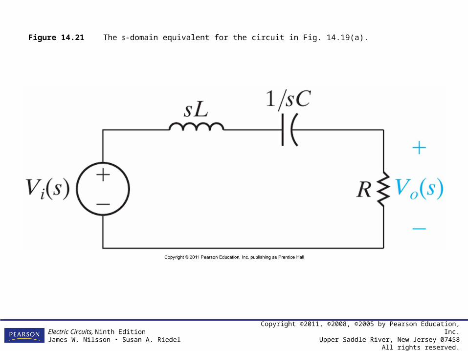
Figure 14.21 The s-domain equivalent for the circuit in Fig. 14.19(a).
Copyright ©2011, ©2008, ©2005 by Pearson Education, Inc.Upper Saddle River, New Jersey 07458
All rights reserved.
Electric Circuits, Ninth EditionJames W. Nilsson • Susan A. Riedel
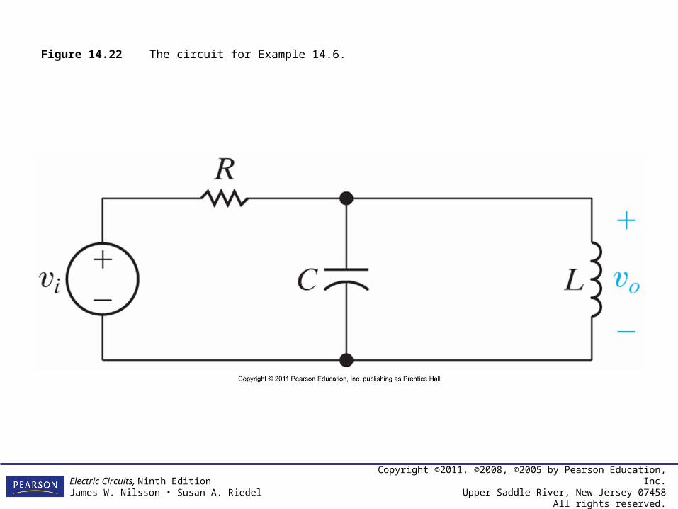
Figure 14.22 The circuit for Example 14.6.

Copyright ©2011, ©2008, ©2005 by Pearson Education, Inc.Upper Saddle River, New Jersey 07458
All rights reserved.
Electric Circuits, Ninth EditionJames W. Nilsson • Susan A. Riedel
Figure 14.23 The s-domain equivalent of the circuit in Fig. 14.22.

Copyright ©2011, ©2008, ©2005 by Pearson Education, Inc.Upper Saddle River, New Jersey 07458
All rights reserved.
Electric Circuits, Ninth EditionJames W. Nilsson • Susan A. Riedel
Figure 14.24 The circuit for Example 14.7.
Copyright ©2011, ©2008, ©2005 by Pearson Education, Inc.Upper Saddle River, New Jersey 07458
All rights reserved.
Electric Circuits, Ninth EditionJames W. Nilsson • Susan A. Riedel
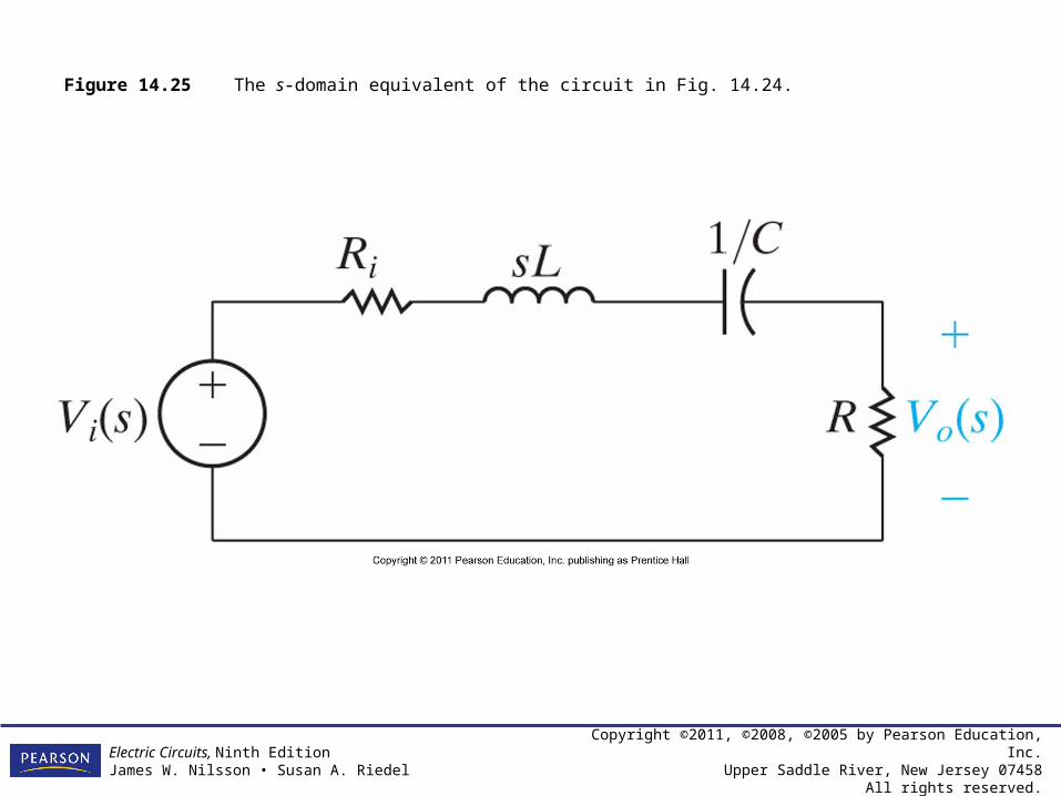
Figure 14.25 The s-domain equivalent of the circuit in Fig. 14.24.
Copyright ©2011, ©2008, ©2005 by Pearson Education, Inc.Upper Saddle River, New Jersey 07458
All rights reserved.
Electric Circuits, Ninth EditionJames W. Nilsson • Susan A. Riedel
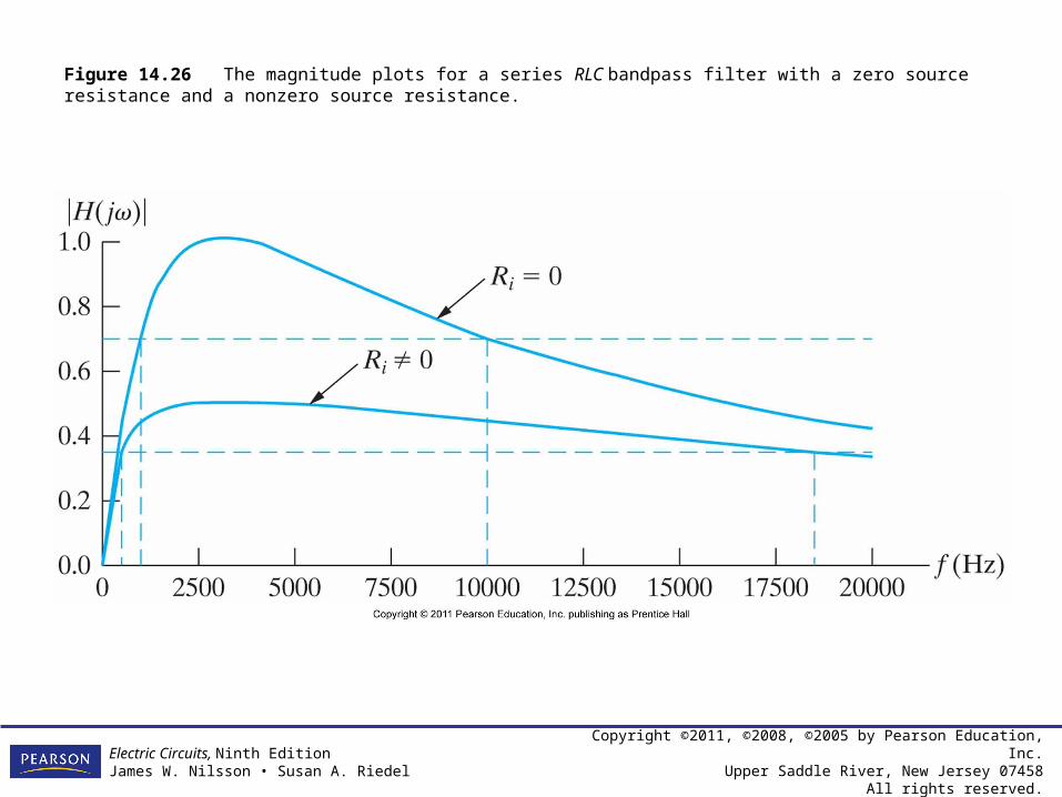
Figure 14.26 The magnitude plots for a series RLC bandpass filter with a zero source resistance and a nonzero source resistance.
Copyright ©2011, ©2008, ©2005 by Pearson Education, Inc.Upper Saddle River, New Jersey 07458
All rights reserved.
Electric Circuits, Ninth EditionJames W. Nilsson • Susan A. Riedel
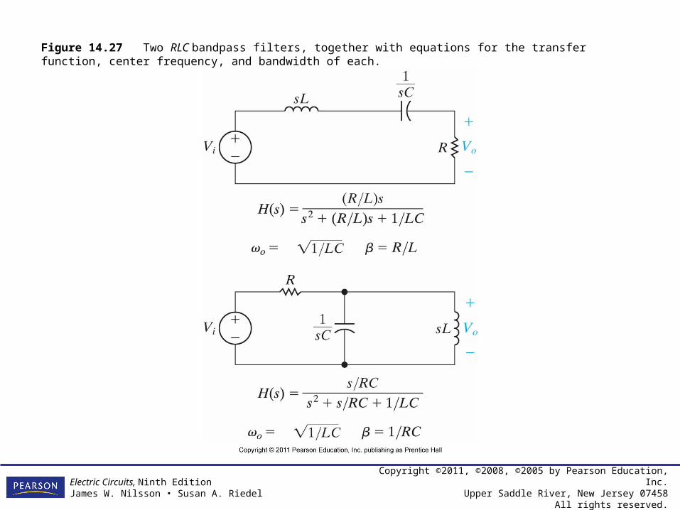
Figure 14.27 Two RLC bandpass filters, together with equations for the transfer function, center frequency, and bandwidth of each.
Copyright ©2011, ©2008, ©2005 by Pearson Education, Inc.Upper Saddle River, New Jersey 07458
All rights reserved.
Electric Circuits, Ninth EditionJames W. Nilsson • Susan A. Riedel
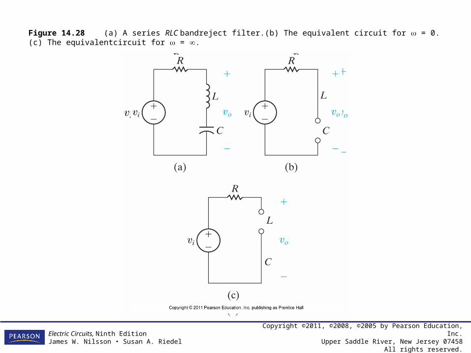
Figure 14.28 (a) A series RLC bandreject filter.(b) The equivalent circuit for = 0. (c) The equivalentcircuit for = .
Copyright ©2011, ©2008, ©2005 by Pearson Education, Inc.Upper Saddle River, New Jersey 07458
All rights reserved.
Electric Circuits, Ninth EditionJames W. Nilsson • Susan A. Riedel
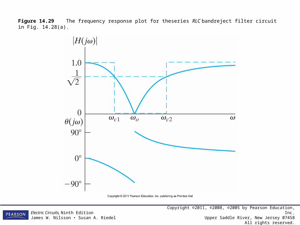
Figure 14.29 The frequency response plot for theseries RLC bandreject filter circuit in Fig. 14.28(a).
Copyright ©2011, ©2008, ©2005 by Pearson Education, Inc.Upper Saddle River, New Jersey 07458
All rights reserved.
Electric Circuits, Ninth EditionJames W. Nilsson • Susan A. Riedel
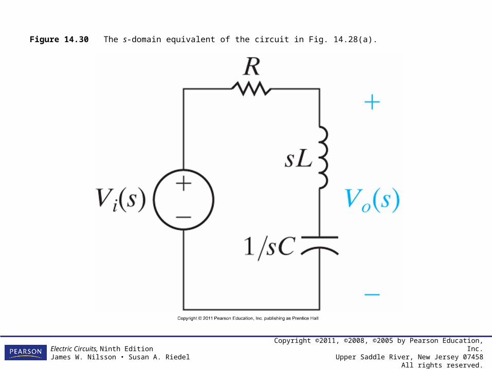
Figure 14.30 The s-domain equivalent of the circuit in Fig. 14.28(a).

Copyright ©2011, ©2008, ©2005 by Pearson Education, Inc.Upper Saddle River, New Jersey 07458
All rights reserved.
Electric Circuits, Ninth EditionJames W. Nilsson • Susan A. Riedel
Figure 14.31 Two RLC bandreject filters, together with equations for the transfer function, center frequency, and bandwidth of each.
Copyright ©2011, ©2008, ©2005 by Pearson Education, Inc.Upper Saddle River, New Jersey 07458
All rights reserved.
Electric Circuits, Ninth EditionJames W. Nilsson • Susan A. Riedel
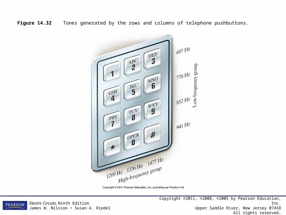
Figure 14.32 Tones generated by the rows and columns of telephone pushbuttons.
Copyright ©2011, ©2008, ©2005 by Pearson Education, Inc.Upper Saddle River, New Jersey 07458
All rights reserved.
Electric Circuits, Ninth EditionJames W. Nilsson • Susan A. Riedel
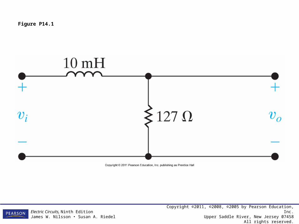
Figure P14.1
Copyright ©2011, ©2008, ©2005 by Pearson Education, Inc.Upper Saddle River, New Jersey 07458
All rights reserved.
Electric Circuits, Ninth EditionJames W. Nilsson • Susan A. Riedel
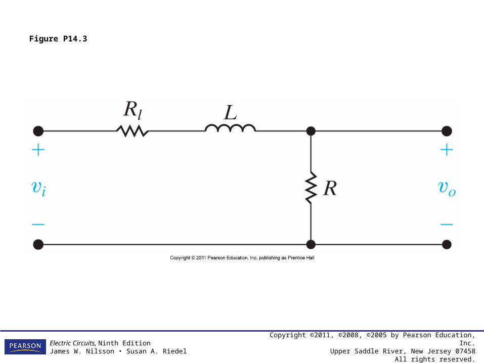
Figure P14.3
Copyright ©2011, ©2008, ©2005 by Pearson Education, Inc.Upper Saddle River, New Jersey 07458
All rights reserved.
Electric Circuits, Ninth EditionJames W. Nilsson • Susan A. Riedel
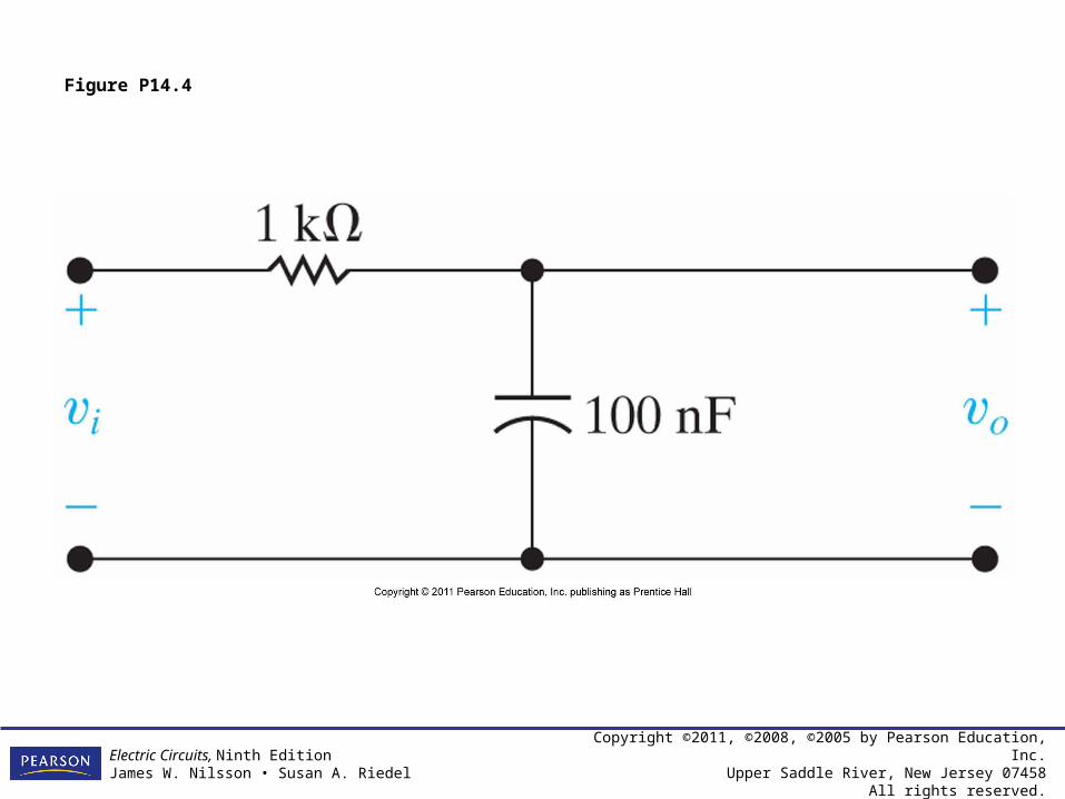
Figure P14.4
Copyright ©2011, ©2008, ©2005 by Pearson Education, Inc.Upper Saddle River, New Jersey 07458
All rights reserved.
Electric Circuits, Ninth EditionJames W. Nilsson • Susan A. Riedel
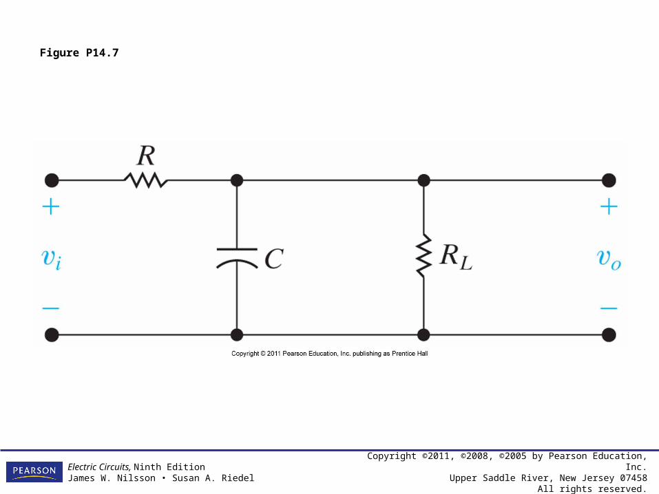
Figure P14.7

Copyright ©2011, ©2008, ©2005 by Pearson Education, Inc.Upper Saddle River, New Jersey 07458
All rights reserved.
Electric Circuits, Ninth EditionJames W. Nilsson • Susan A. Riedel
Figure P14.8
Copyright ©2011, ©2008, ©2005 by Pearson Education, Inc.Upper Saddle River, New Jersey 07458
All rights reserved.
Electric Circuits, Ninth EditionJames W. Nilsson • Susan A. Riedel
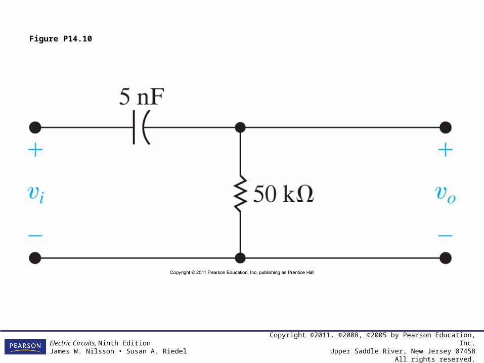
Figure P14.10

Copyright ©2011, ©2008, ©2005 by Pearson Education, Inc.Upper Saddle River, New Jersey 07458
All rights reserved.
Electric Circuits, Ninth EditionJames W. Nilsson • Susan A. Riedel
Figure P14.11
Copyright ©2011, ©2008, ©2005 by Pearson Education, Inc.Upper Saddle River, New Jersey 07458
All rights reserved.
Electric Circuits, Ninth EditionJames W. Nilsson • Susan A. Riedel
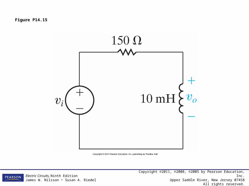
Figure P14.15

Copyright ©2011, ©2008, ©2005 by Pearson Education, Inc.Upper Saddle River, New Jersey 07458
All rights reserved.
Electric Circuits, Ninth EditionJames W. Nilsson • Susan A. Riedel
Figure P14.22
Copyright ©2011, ©2008, ©2005 by Pearson Education, Inc.Upper Saddle River, New Jersey 07458
All rights reserved.
Electric Circuits, Ninth EditionJames W. Nilsson • Susan A. Riedel
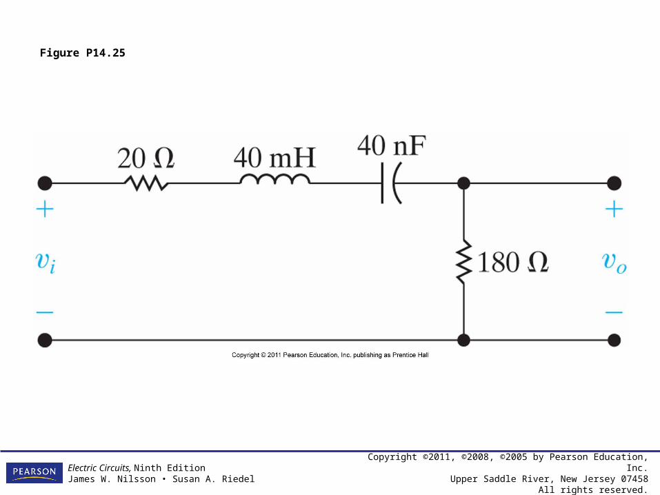
Figure P14.25
Copyright ©2011, ©2008, ©2005 by Pearson Education, Inc.Upper Saddle River, New Jersey 07458
All rights reserved.
Electric Circuits, Ninth EditionJames W. Nilsson • Susan A. Riedel
Figure P14.30

Copyright ©2011, ©2008, ©2005 by Pearson Education, Inc.Upper Saddle River, New Jersey 07458
All rights reserved.
Electric Circuits, Ninth EditionJames W. Nilsson • Susan A. Riedel
Figure P14.31

Copyright ©2011, ©2008, ©2005 by Pearson Education, Inc.Upper Saddle River, New Jersey 07458
All rights reserved.
Electric Circuits, Ninth EditionJames W. Nilsson • Susan A. Riedel
Figure P14.32
Copyright ©2011, ©2008, ©2005 by Pearson Education, Inc.Upper Saddle River, New Jersey 07458
All rights reserved.
Electric Circuits, Ninth EditionJames W. Nilsson • Susan A. Riedel
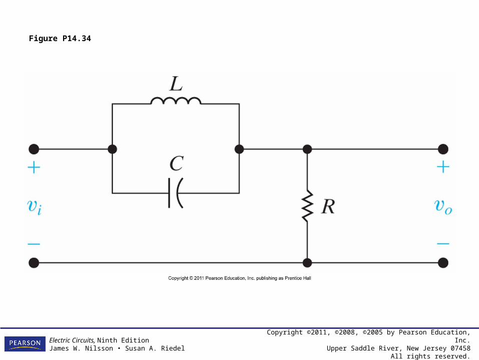
Figure P14.34
Copyright ©2011, ©2008, ©2005 by Pearson Education, Inc.Upper Saddle River, New Jersey 07458
All rights reserved.
Electric Circuits, Ninth EditionJames W. Nilsson • Susan A. Riedel
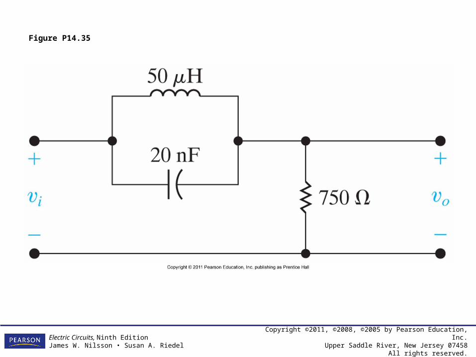
Figure P14.35

Copyright ©2011, ©2008, ©2005 by Pearson Education, Inc.Upper Saddle River, New Jersey 07458
All rights reserved.
Electric Circuits, Ninth EditionJames W. Nilsson • Susan A. Riedel
Figure P14.36
Copyright ©2011, ©2008, ©2005 by Pearson Education, Inc.Upper Saddle River, New Jersey 07458
All rights reserved.
Electric Circuits, Ninth EditionJames W. Nilsson • Susan A. Riedel
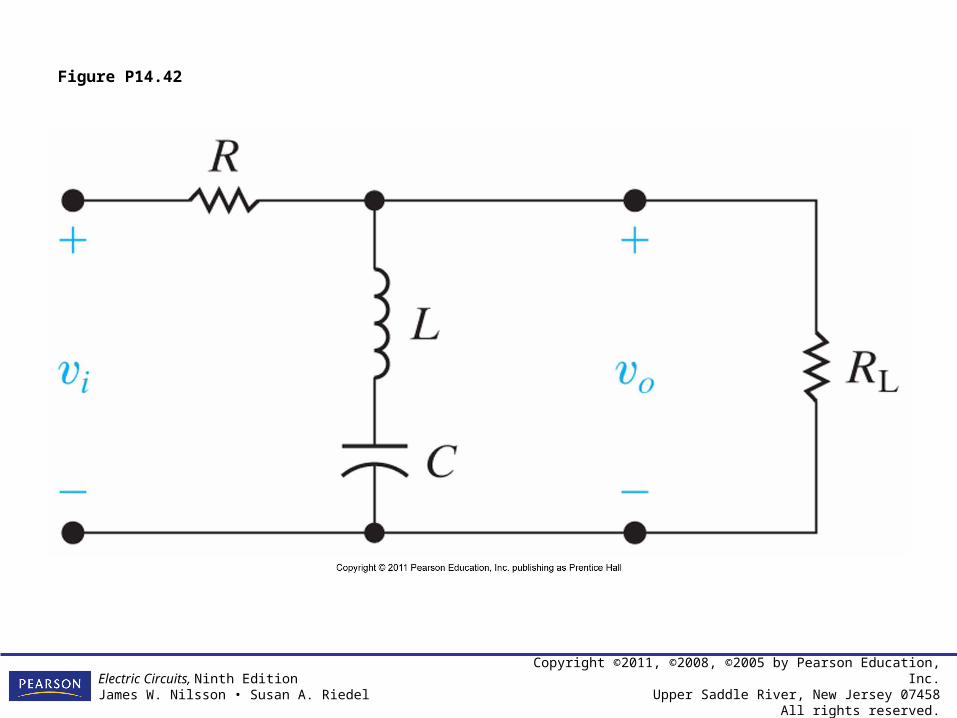
Figure P14.42


![[Young marketers elite program] assignment 14.1 thiên an huỳnh phong](https://static.fdocuments.in/doc/165x107/555365a4b4c905031f8b519f/young-marketers-elite-program-assignment-141-thien-an-huynh-phong.jpg)