Fig. ESH-01 - Do not install …hi-velocity.com/en/electricheater/Module-ESH-Electric...inside the...
7
www.hi-velocity.com © 1995-2013 Energy Saving Products Ltd. The Electrical Strip Heater (ESH) is an electric resistance heater that slides into the fan coil on the leaving air side (supply side) of the blower. This heater can be used for primary heating or supplemental heat (auxiliary heating) for heat pumps. The ESH has “0” clearance to combustibles, and requires minimum clearances on the access side for maintenance and servicing (see Fan Coil Placement: Module FCP). Allow 18” minimum of straight plenum duct from the supply of the air handler before any branch outlets, tees or elbows. The ESH elements are rated for 240V 60 Hz. Higher voltages are not recommended. When lower voltages are supplied, de-rate the capacity of the ESH accordingly. 230V = 92%, 220V= 84%, 208V = 75%. Use only wires suitable for 167° F (75°C). Wiring the Electrical Strip Heater Electrical Strip Heater Table ESH-01 Kw Volts/ Phase # of feeders Circuit Breakers 5 240/1 1 X 20.8 1 X 30A 10 240/1 1 X 41.6 1 X 60A’ 15 240/1 1 X 20.8 1 X 41.6 1 X 30A 1 X 60A 18 240/1 1 X 31.2 1 X 41.6 1 X 40A 1 X 60A 20 240/1 2 X 41.6 2 X 60A 23 240/1 2 X 47.0 2 X 60A Installation The ESH is labeled with a directional airflow sticker; when placing the ESH, the sticker shall be in the direction of the air flow. There is a minimum air flow requirement for the electric strip heater: The HE-Z/HE/HV-50 fan coils and the HE-Z/HE/HV-70 fan coils require a minimum of six 2”x10’ AFD outlets per 5 kW. The HE-Z/HE/HV-100 fan coils require a minimum of seven 2”x10’ AFD outlets per 5 kW. *One HE x 10’ AFD is equivalent to two - 2” x 10’ AFDs Remove the shipping covers and inspect the heater carefully. Check the ESH for any shipping damage, check the heating elements for any loose connections and check all porcelain insulators for any breaks. Report any damage to the manufacturer. DO NOT INSTALL DAMAGED HEATER. Module ESH PLEASE NOTE: THE ESH MUST BE WIRED TO A DEDICATED BREAKER, SEPARATE FROM THE FAN COIL. Install the ESH in the supply air side of the fan coil. Remove the coil access door and simply slide the coil into place. The heating elements (Fig. 01) must always be installed horizontally. Seal the void between the fan coil and the ESH with the foam tape supplied with the unit or with a suitable sealant. Mount the ESH onto the fan coil cabinet with 4 self tapping screws from inside the ESH wiring access door. Seal any additional openings with a suitable sealing compound. The air handler and the ESH must have independent power supplies. Disconnect all power sources before opening the control box and working within. Wires shall be sized according to local electrical codes and ordinances. All wires must be brought in through knock-outs. See Table ESH-01 for feeder quantity of feeder ampacity. The ESH 5 and 10 kW units have one single 240V breaker; the 15 kW to 23 kW units come complete with two supply circuit breakers. These two circuits can be joined together using a Jumper Bar (Square D® – QOU14100JBAF, not supplied) designed to use one pair of larger gauge wire instead of two smaller gauge wires. Install as per manufacturers guide lines, and according to code. A disconnect switch close to the heater will be required. DO NOT INSTALL ESH AS SHOWN, WITH CONTROLS ON TOP Control circuit wiring between the heater terminals #1 and #2 on the ESH use Class 2 - 18 gauge wire to the zone valve terminals in the fan control box. Electrical Strip Heater Installation (1/7) Fig. ESH-01 - Do not install elements Vertically Module ESH Electrical Strip Heater Installation (1/7)
Transcript of Fig. ESH-01 - Do not install …hi-velocity.com/en/electricheater/Module-ESH-Electric...inside the...

www.hi-velocity.com
© 1995-2013 Energy Saving Products Ltd.
The Electrical Strip Heater (ESH) is an electric resistance heater that slides into the fan coil on the leaving air side (supply side) of the blower. This heater can be used for primary heating or supplemental heat (auxiliary heating) for heat pumps. The ESH has “0” clearance to combustibles, and requires minimum clearances on the access side for maintenance and servicing (see Fan Coil Placement: Module FCP). Allow 18” minimum of straight plenum duct from the supply of the air handler before any branch outlets, tees or elbows.
The ESH elements are rated for 240V 60 Hz. Higher voltages are not recommended. When lower voltages are supplied, de-rate the capacity of the ESH accordingly. 230V = 92%, 220V= 84%, 208V = 75%. Use only wires suitable for 167° F (75°C).
Wiring the Electrical Strip Heater
Electrical Strip Heater
Table ESH-01
Kw Volts/Phase
# of feeders
Circuit Breakers
5 240/1 1 X 20.8 1 X 30A
10 240/1 1 X 41.6 1 X 60A’
15 240/1 1 X 20.8 1 X 41.6 1 X 30A 1 X 60A
18 240/1 1 X 31.2 1 X 41.6 1 X 40A 1 X 60A
20 240/1 2 X 41.6 2 X 60A
23 240/1 2 X 47.0 2 X 60A
Installation
The ESH is labeled with a directional airflow sticker; when placing the ESH, the sticker shall be in the direction of the air flow.
There is a minimum air flow requirement for the electric strip heater:
The HE-Z/HE/HV-50 fan coils and the HE-Z/HE/HV-70 fan coils require a minimum of six 2”x10’ AFD outlets per 5 kW.
The HE-Z/HE/HV-100 fan coils require a minimum of seven 2”x10’ AFD outlets per 5 kW.
*One HE x 10’ AFD is equivalent to two - 2” x 10’ AFDs
Remove the shipping covers and inspect the heater carefully. Check the ESH for any shipping damage, check the heating elements for any loose connections and check all porcelain insulators for any breaks. Report any damage to the manufacturer. DO NOT INSTALL DAMAGED HEATER.
Module ESH
PLEASE NOTE: THE ESH MUST BE WIRED TO A DEDICATED BREAKER, SEPARATE FROM THE FAN COIL.
Install the ESH in the supply air side of the fan coil. Remove the coil access door and simply slide the coil into place. The heating elements (Fig. 01) must always be installed horizontally. Seal the void between the fan coil and the ESH with the foam tape supplied with the unit or with a suitable sealant. Mount the ESH onto the fan coil cabinet with 4 self tapping screws from inside the ESH wiring access door. Seal any additional openings with a suitable sealing compound.
The air handler and the ESH must have independent power supplies. Disconnect all power sources before opening the control box and working within. Wires shall be sized according to local electrical codes and ordinances. All wires must be brought in through knock-outs. See Table ESH-01 for feeder quantity of feeder ampacity.
The ESH 5 and 10 kW units have one single 240V breaker; the 15 kW to 23 kW units come complete with two supply circuit breakers. These two circuits can be joined together using a Jumper Bar (Square D® – QOU14100JBAF, not supplied) designed to use one pair of larger gauge wire instead of two smaller gauge wires. Install as per manufacturers guide lines, and according to code. A disconnect switch close to the heater will be required.
Do not install EsH as sHown, witH controls on top
Control circuit wiring between the heater terminals #1 and #2 on the ESH use Class 2 - 18 gauge wire to the zone valve terminals in the fan control box.
Electrical Strip Heater Installation (1/7)
Fig. ESH-01 - Do not install elements Vertically
Module ESH Electrical Strip Heater Installation (1/7)

www.hi-velocity.com
© 1995-2013 Energy Saving Products Ltd.
OperationThe low voltage signals that energize the ESH come from
the air handler’s zone valve terminals (W1/W2 output and C). These are to be connected to #1 and #2 of the ESH. Note: This connection is polarity sensitive. The W2 output is energized with 24v with a call for heat from a W2 call on the air handler’s terminal board. W2 will also energize the heating fan speed on the air handler. For air handler to ESH low voltage wiring, see next page. High voltage wiring of the ESH can be viewed on the inside of the ESH front panel.
On a demand for heat the TH-24 electronic sequencer will energize the heating elements in sequence. When the thermostat is satisfied, all the elements and blower will be de-energized.
Within the ESH, there are automatic reset thermal cut-out disc type safety devices at a fixed temperature that open the control circuit when a set point is reached. When the overheating conditions have disappeared, it automatically resets and returns the heater to normal operating conditions.
Zoning
The standard off the shelf ESH has 2 stages and therefore can be used with a maximum of 2 zones. Energy Saving Products Ltd. also offers a special electric strip module for increased zoning capabilities. Please contact the factory for additional information.
MaintenanceESH heaters have been designed to operate long term without
issue. Those responsible for equipment and maintenance should be aware of the following suggestions:
Periodic visual inspection: This precautionary step will help to keep your unit operating properly. Inspect the unit periodically and be on the lookout for any first signs of problems: Accumulation of dust on the heating elements, signs of overheating on the heater frame, traces of water or rust on the control box.
Electrical inspection: Two weeks after start up, all electric connections to contactors should be re-checked and tightened. Before each heating season, the following steps are recommended:
• Check all fuses
• Check resistance to ground for each circuit
• Check resistance phase to phase for each circuit
• Check the tightness of connections at all contactors andheating elements
• Check all contactors
• Check electrical connections to heating elements,magnetic contactors, and main power plugs.
It is recommended that this inspection be performed monthly for the first four months of operation. Following that, two inspections per heating season is sufficient.
Off Season MaintenanceShould a heater be shut off for a long period, we recommend
that you carefully check the resistance to ground for each circuit. It is important not to power a heater when too low a resistance to ground has been measured. It is also recommended to pay attention to any other heater operating in normal conditions. All control components should be maintained and checked according to respective manufacturer’s instructions. Any defective components should be replaced only with identical origin parts.
Module ESHElectrical Strip Heater Installation (2/7)
Specifications ESH - 650 ESH - 750 ESH - 1100
Matching Fan Coil HE-Z/HE/HV - 50/51 BULV - 50 BU
HE-Z/HE/HV - 70/71 BULV-Z/LV-E - 1050 BU
LV - 70 BU
HE-Z/HE/HV - 100/101 BULV-120/140 BU
Part Numbers
5kw - 10025650005 5kw - 10025750005 10kw - 10025110010
10kw - 10025650010 10kw - 10025750010 15kw - 10025110015
15kw - 10025650015 15kw - 10025750015 18kw - 10025110018
18kw - 10025750018 20kw - 10025110020
23kw - 10025110023
Volts 240 240 240
Phase 1 1 1
Shipping Weight 21 lbs (9.5kg) 27 lbs (12kg) 28 lbs (13kg)
Module Size Length 20” (508mm) 24” (610mm) 31”(788mm)
Width 13” (330mm) 13” (330mm) 13” (330mm)
Height 18” (457mm) 18” (457mm) 18” (457mm)
Module ESH Electrical Strip Heater Installation (2/7)

TH
ER
MO
STA
T C
ON
NE
CT
ION
S
R -
EM
ER
GE
NC
Y D
ISC
ON
NE
CT
C -
24
VA
C C
OM
MO
N R
o -
24
VA
C I
NP
UT
R
i -
24
VA
C O
UT
PU
T
24
VA
C O
UT
PU
TW
1 -
FIR
ST
STA
GE
HE
AT
W2
- S
EC
ON
D S
TA
GE
HE
AT
(
OR
SIN
GL
E S
TA
GE
) Y
1 -
FIR
ST
STA
GE
CO
OL
ING
Y2
- S
EC
ON
D S
TA
GE
CO
OL
ING
(O
R S
ING
LE
STA
GE
)
C -
24
VA
C C
OM
MO
N
G -
TH
ER
MO
STA
T F
AN
SW
ITC
H
D -
Y S
PE
ED
OV
ER
RID
E (
70
% O
F Y
)O
/B -
HE
AT
PU
MP
RE
VE
RS
ING
A
UX
ILIA
RY
HE
AT
ING
RE
LA
Y
24 V
AC
OU
TP
UT
CO
NN
EC
TIO
NS
X1
- F
RE
EZ
E S
TA
T X
2 -
FR
EE
ZE
STA
T W
1 -
HE
AT
ING
(W
1)
24
VA
C O
UT
PU
T W
2 -
HE
AT
ING
(W
2)
24
VA
C O
UT
PU
T Y
2 -
C
ON
DE
NS
ING
UN
IT 2
4 V
AC
OU
TP
UT
Y1
-
CO
ND
EN
SIN
G U
NIT
24
VA
C O
UT
PU
T
C -
2
4 V
AC
CO
MM
ON
R
-
24
VA
C O
UT
PU
T
L
ED
LIG
HT
IN
DIC
AT
OR
SL
ED
1 -
GR
EE
N L
IGH
T, P
UM
P T
IME
RS
/
O
PE
RA
TIO
N M
OD
E I
ND
ICA
TO
R
LE
D 2
- B
LU
E L
IGH
T, P
RE
SS
UR
E S
EN
SO
R
N
- N
EU
TR
AL
L
- L
INE
VO
LTA
GE
A1
- A
UX
ILIA
RY
NO
RM
AL
LY O
PE
NA
2 -
AU
XIL
IAR
Y N
OR
MA
LLY
CL
OS
ED
A3
- A
UX
ILIA
RY
CO
MM
ON
JU
MP
ER
PIN
SE
TT
ING
S
AU
XIL
IAR
Y R
EL
AY
TIM
ER
(S
EE
NO
TE
S)
H3
NO
TE
S:
1)
US
E T
HE
RM
OS
TA
T F
AN
SW
ITC
H T
O D
ISA
BL
E/E
NA
BL
E C
ON
TIN
UO
US
FA
N.
2)
‘C’ T
ER
MIN
AL O
N T
HE
RM
OS
TA
T (
CO
MM
ON
) IS
NO
T N
EE
DE
D F
OR
SO
ME
TH
ER
MO
STA
TS
C
ON
SU
LT T
HE
RM
OS
TA
T I
NS
TR
UC
TIO
NS
FO
R D
ETA
ILS
.3
) W
1 A
ND
W2
AC
TIV
AT
ES
AU
XIL
IAR
Y R
EL
AY
(A
3)
ON
CA
LL A
ND
CA
N B
E U
SE
D W
ITH
A1
A
ND
/OR
A2
AS
DR
Y C
ON
TA
CT
S, A
RM
ED
24
VA
C F
RO
M T
HE
‘R’ T
ER
MIN
AL
, O
R A
RM
ED
11
0v
FR
OM
TH
E ‘L
’ TE
RM
INA
L.
4) A
UX
ILIA
RY
HE
AT
ING
RE
LA
Y T
IME
R A
CT
IVA
TE
S C
IRC
UIT
FO
R 5
MIN
UT
ES
EV
ER
Y 2
4
HO
UR
S S
TA
RT
ING
WH
EN
PO
WE
R I
S A
PP
LIE
D T
O T
HE
UN
IT.
5)
LE
D 1
: IN
DIC
AT
OR
LIG
HT
FO
R F
AN
SP
EE
D O
PE
RA
TIO
N A
ND
AU
XIL
IAR
Y R
EL
AY
O
PE
RA
TIO
N. S
EE
MA
NU
AL F
OR
LIG
HT
OP
ER
AT
ION
SE
QU
EN
CE
.
H1
EM
ER
GE
NC
Y D
ISC
ON
NE
CT:
RE
MO
VE
PIN
IF
WIR
ED
TO
EM
ER
GE
NC
Y D
ISC
ON
NE
CT
H2
TIM
ER
: M
OD
E:
AU
TO
- F
AN
SP
EE
D M
OD
UL
AT
ES
DE
PE
ND
ING
UP
ON
STA
TIC
PR
ES
SU
RE
MA
NU
AL
- F
AN
SP
EE
D O
PE
RA
TE
S A
T T
RIM
PO
TS
SE
T A
IR F
LO
W
H4
DE
LA
Y:
Y/2
0 S
EC
ON
D,
W/3
0 S
EC
ON
D F
AN
DE
LA
Y.
Y A
ND
W 3
0 S
EC
ON
D P
OS
T P
UR
GE
.
WH
EN
AD
JU
ST
TR
IM P
OT
S:
ON
PO
WE
R S
TA
RT
UP, A
LL
OW
30
SE
CO
ND
S
FO
R S
YS
TE
M T
O P
RE
SS
UR
IZE
BE
FO
RE
MA
KIN
G A
NY
CH
AN
GE
S.
DO
NO
T A
DJU
ST
MO
RE
TH
AN
A ½
TU
RN
AT
A T
IME
, A
LL
OW
45
SE
CO
ND
S
BE
TW
EE
N A
DJU
ST
ME
NT
S F
OR
TH
E P
SB
TO
RE
AC
H S
ET
PO
INT.
AU
TO
MO
DE
: L
ED
2 W
ILL
SP
OR
AD
ICA
LLY
FL
ICK
ER
BL
UE
(O
N/O
FF
) T
O
SH
OW
TH
AT
IT
IS
PR
OP
ER
LY S
EN
SIN
G P
RE
SS
UR
E I
N T
HE
SY
ST
EM
.*
NO
LIG
HT
IN
DIC
AT
ES
TR
IM P
OT
IS
AB
OV
E N
OR
MA
L O
PE
RA
TIN
G
RA
NG
E (
CO
UN
TE
R C
LO
CK
WIS
E D
EC
RE
AS
E).
* S
OL
ID L
IGH
T I
ND
ICA
TE
S T
RIM
PO
T I
S B
EL
OW
NO
RM
AL O
PE
RA
TIN
G
RA
NG
E (
CLO
CK
WIS
E,
INC
RE
AS
E).
MA
NU
AL
MO
DE
: L
ED
2 W
ILL
BE
OF
F, A
DJU
ST
AIR
EA
CH
OF
TH
E F
LO
WS
TO
D
ES
IRE
D C
FM
/LP
S O
UT
PU
T.
* D
EC
RE
AS
E A
IR F
LO
W A
DJU
ST
TR
IM P
OT
CO
UN
TE
R C
LO
CK
WIS
E*
INC
RE
AS
E A
IR F
LO
W A
DJU
ST
TR
IM P
OT
CL
OC
KW
ISE
RE
FE
R A
ND
CO
MP
LE
TE
CO
MM
ISS
ION
ING
RE
PO
RT
PR
IOR
TO
NO
RM
AL
OP
ER
AT
ION
. F
OR
FU
LL D
ETA
ILS
, R
EP
OR
T I
S A
VA
ILA
BL
E I
N T
HE
IN
STA
LL
AT
ION
MA
NU
AL O
R O
NL
INE
AT
WW
W.H
I-V
EL
OC
ITY.C
OM
DE
CR
EA
SE
AIR
FL
OW
(CO
UN
TE
R C
LO
CK
WIS
E)
FA
N A
DJ
US
TM
EN
T T
RIM
PO
TS
INC
RE
AS
E A
IR F
LO
W(C
LO
CK
WIS
E)
PO
WE
R I
NP
UT:
20
8-2
40
/1/6
0
PO
WE
R I
NP
UT:
11
0-1
20
/1/6
0
1 2
3 4
5 6
7 8
9 1
0 1
1 1
2
L/L
1N
/L2
UV
WP
E
P0I
Pa
ram
ete
r
Va
lue
WEG CONTROLLER
W1
W2
CR
Y2
Y1
DO
/BG
R Y1 W2 W1 X1 X2Y2CF1
AUXILIARY RELAY(HEATING)
LL
L2
L2
NL
1L
1
A3 A2 A1L N
COOL HEAT FANLED
L1J8
ON
OF
F
H2
TIM
ER
AU
TO
MA
N
H3
MO
DE
ON
OF
F
H4
DE
LA
Y
J5J7
J4
U2
J3
R8
R7
R6G C H F
318.2
3 P
cb
w-0
01sep
-039
-
+
J2
NC RiRo
H1J9
J1
LED
L2
Wh
ite
Ora
ng
e
Bla
ck
Re
dB
lac
k
Eq
uip
me
nt
Gro
un
d
L1
N
Ground
WH
BK
G LIN
E I
N
24v / 2
0va
TR
AN
SF
OR
ME
R
TH
ER
MO
STA
T
24v OUTPUT
PS
B C
IRC
UIT
BO
AR
D
L2
R
EMERGENCY DISCONNECT
208-2
40v P
OW
ER
CA
BL
E
110/1
20 V
AC
20
8-2
40
/1/6
0
VF
D
208-2
40 V
AC
BK
WH
GR
MO
TO
R L
EA
DS
PL
UG
(3 P
HA
SE
)
T
RIM
PO
TS
(C
OO
LIN
G,
HE
AT
ING
, C
ON
STA
NT
FA
N)
-
AT
MO
SP
HE
RIC
PR
ES
SU
RE
+ D
UC
T P
RE
SS
UR
E
0-1
0 V
DC
Bla
ck
Wir
e (
-)
+-
Re
d W
ire
(+
)
W1
W2
CR
Y2
Y1
DO
/BG
R Y1 W2 W1 X1 X2Y2CF1
AUXILIARY RELAY(HEATING)
LL
L2
L2
NL
1L
1
A3 A2 A1L N
COOL HEAT FANLED
L1J8
ON
OF
F
H2
TIM
ER
AU
TO
MA
N
H3
MO
DE
ON
OF
F
H4
DE
LA
Y
J5J7
J4
U2
J3
R8
R7
R6G C H F
31
8.2
3 P
cb
w-0
01
se
p-0
39
-
+
J2
NC RiRo
H1J9
J1
LED
L2
PS
B C
IRC
UIT
BO
AR
D
TH
ER
MO
STA
T
24v OUTPUTEMERGENCY DISCONNECT
1 2
3 4
5 6
7 8
9 1
0 1
1 1
2
L/L
1N
/L2
UV
WP
E
P0I
Pa
ram
ete
r
Va
lue
WEG CONTROLLER
Wh
ite
Bla
ck
Ora
ng
e
Re
dB
lac
k
Eq
uip
me
nt
Gro
un
d
L
N
Ground
WH
BK
G LIN
E I
N
24v / 2
0va
TR
AN
SF
OR
ME
R
VF
D
110-1
20 V
AC
MO
TO
R L
EA
DS
PL
UG
(3 P
HA
SE
)
11
0-1
20
v P
OW
ER
CA
BL
E
110/1
20 V
AC
11
0-1
20
/1/6
0
BK
WH
GR
T
RIM
PO
TS
(C
OO
LIN
G,
HE
AT
ING
, C
ON
STA
NT
FA
N)
-
AT
MO
SP
HE
RIC
PR
ES
SU
RE
+ D
UC
T P
RE
SS
UR
E
0-1
0 V
DC
Bla
ck
Wir
e (
-)
+-
Re
d W
ire
(+
)
ES
P 3
18
.23
MA
Y.9
www.hi-velocity.com
Module ESHElectrical Strip Heater Installation (3/7)
Module ESH Electrical Strip Heater Installation (3/7) © 1995-2013 Energy Saving Products Ltd.
Electric Strip Coil Wiring - HE-Z Series

www.hi-velocity.com
© 1995-2013 Energy Saving Products Ltd.
Electric Strip Coil Wiring - HE-Z Series
Module ESH Electrical Strip Heater Installation (. /7)
Module ESHElectrical Strip Heater Installation (4/7)
En
erg
y S
avin
g P
rod
ucts
12615-1
24 S
treet,
Ed
mo
nto
n, A
B T
5L
-0N
8E
SP
315.0
8
HE
AT
PU
MP
C/W
CO
ND
EN
SE
R D
EF
RO
ST
CY
CL
EE
LE
CT
RIC
BA
CK
-UP
2 S
tag
e C
oo
lin
g 3
Sta
ge H
eati
ng
(E
lectr
ic)
Heat
pu
mp
c/w
co
nd
en
ser
defr
ost
cycle
W1
W2
CR
Y2
Y1
DO
/BG
R Y1 W2 W1 X1 X2Y2C
A3 A2 A1L N
J5J7
J4
OP
TIO
NA
L
15-2
3 K
W U
NIT
ST
HR
OU
GH
TH
ER
MO
STA
T
STA
GIN
G T
HE
AN
TI-
ICE
CO
NT
RO
L
O/B
YR
CW
1
CO
ND
EN
SE
R
THE
RM
OS
TAT
EL
EC
TR
IC S
TR
IP2
4V
TE
RM
INA
LS
TW
OS
TA
GE
C 1 2
12
C RiRo
H1J9
O/B
YR
GC
W2
E
1 S
tag
e C
oo
lin
g 2
Sta
ge H
eati
ng
(E
lectr
ic)
Heat
pu
mp
c/w
co
nd
en
ser
defr
ost
cycle
SE
T A
UX
ILIA
RY
TIM
ER
TO
TH
E “
OF
F”
PO
SIT
ION
W1
W2
CR
Y2
Y1
DO
/BG
R Y1 W2 W1 X1 X2Y2C
A3 A2 A1L N
J5J7
J4
C RiRo
H1J9
OP
TIO
NA
L
15-2
3 K
W U
NIT
ST
HR
OU
GH
TH
ER
MO
STA
T
STA
GIN
G T
HE
EL
EC
TR
IC S
TR
IP2
4V
TE
RM
INA
LS
TW
OS
TA
GE
C 1 2
12
O/B
Y2
Y1
RC
W1
CO
ND
EN
SE
R
EW
2C
RY
2G
O/B
THE
RM
OS
TAT
Y1
AN
TI-
ICE
CO
NT
RO
L
EW
2C
RY
2G
O/B
Y1
SE
T A
UX
ILIA
RY
TIM
ER
TO
TH
E “
OF
F”
PO
SIT
ION
12
C 1 2SIN
GL
ES
TA
GE
C 1 2
TW
OS
TA
GE
C 1 2
SIN
GL
E S
TA
GE
EL
EC
TR
IC S
TR
IPIN
TE
RN
AL
24
V
For
optio
nal e
nerg
y sa
vings
inst
all
a o
utd
oor
therm
ost
at to
lim
it th
e u
se o
f th
e s
eco
nd s
tage
of th
e E
SH
. F
or
exa
mple
- 2
sta
gin
g the e
lect
ric
strip in
terr
upt “C
” and “
1”
or
“C”
and “
2”
with
a
outd
oor
stat as
show
n b
elo
w. T
his
allo
ws
single
st
age o
f th
e tw
o b
anks
of th
e e
lect
ric
strip to
act
ivate
, th
e s
eco
nd s
tage w
ill b
e a
llow
ed to
act
ivate
by
the o
utd
oor
stat.
OP
TIO
NA
L T
HR
OU
GH
OU
T D
OO
R T
HE
RM
OS
TA
TS
TA
GIN
G T
HE
15-2
3 K
W U
NIT
S
WIR
ING
FO
R E
LE
CT
RIC
AL
ST
RIP
HE
AT
ER
(E
SH
)
THE
RM
OS
TAT
WC
RY
G
WC
GR
Y
W1
W2
CR
Y2
Y1
DO
/BG
R Y1 W2 W1 X1 X2Y2C
A3 A2 A1L N
J5J7
J4
1 S
tag
e H
eati
ng
21
EL
EC
TR
IC S
TR
IPC
ON
TA
CT
S 2
4V
AC

© 1995-2009 Energy Saving Products Ltd.
Module ESHElectrical Strip Heater Installation (5/7)
Module ESH Electrical Strip Heater Installation (5/7)
N - NEUTRAL
l - LINE vOLTAGE
a1 - AUXILIARY NORMALLY OPEN
a2 - AUXILIARY NORMALLY CLOSEd
a3 - AUXILIARY COMMON
x1 - FREEzE STAT TERMINAL
x2 - FREEzE STAT TERMINAL
h1 - CONdENSING UNIT 24v OUTPUT
c - CONdENSING UNIT 24 vAC COMMON
Z1 - HEATING MOdE 24v OUTPUT
c - HEATING MOdE 24v vAC COMMON
mINImum factory dIP settINgsblack Is dIP swItch settINg
ON
1 2 3 4 5 6 7 8
ON
1 2 3 4 5 6 7 8
ON
1 2 3 4 5 6 7 8
HE-50 5-10 kW(1 1/2 Ton Dip Setting)
ON
1 2 3 4 5 6 7 8
HE-50 5-15 kW(2 Ton Dip Setting)
HE-70 5-15 kW(2 1/2 Ton Dip Setting)
ON
1 2 3 4 5 6 7 8
HE-70 5-18 kW(3 Ton Dip Setting)
HE-100 10-18 kW(3 1/2 Ton Dip Setting)
ON
1 2 3 4 5 6 7 8
HE-100 10-20 kW(4 Ton Dip Setting)
ON
1 2 3 4 5 6 7 8
HE-100 10-23 kW(5 Ton Dip Setting)
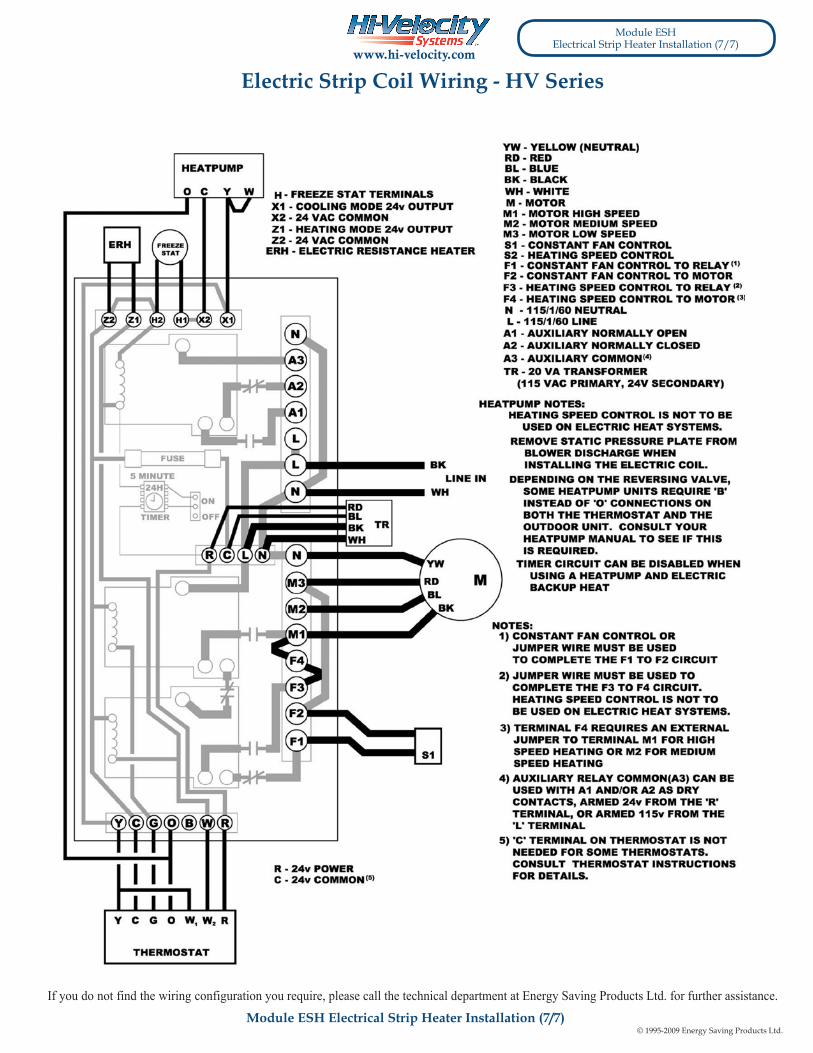
HEAT PUMP NOTES:DEPENDING ON THE REVERSING VALVE, SOME HEAT PUMP UNITS REQUIRE ‘B’ INSTEAD OF ‘O’ CONNECTION ON BOTH THE THER-MOSTAT AND THE OUTDOOR UNIT. CONSULT YOUR HEAT PUMP MANUAL TO SEE IF THIS IS REQUIRED.
TIMER CIRCUIT CAN BE DISABLED WHEN USING A HEAT PUMP AND ELECTRIC BACKUP HEAT.
cautIoNdISCONNECT THE ELECTRIC POWER BEFORE SERvICING
atteNtIoNdECCONNECTER dU CIRCUITd’ALIMENTATION ELECTRIQUE
AvANT L’ENTRE-TIEN
1) USE THERMOSTAT FAN SWITCH TO DISABLE/ENABLECONTINUOUS FAN.
2) ‘C’ TERMINAL ON THERMOSTAT (COMMON) IS NOTNEEDED FOR SOME THERMOSTATS. CONSULT THERMOSTAT INSTRUCTIONS FOR DETAILS.
3) A3 (AUXILIARY RELAY COMMON) CAN BE USED WITH A1 AND/OR A2 AS DRY CONTACTS, ARMED 24v FROM THE ‘R’ TERMINAL, OR ARMED FROM THE ‘L’ TERMINAL.
4) AUXILIARY RELAY TIMER ACTIVATES CIRCUIT FOR 5 MINUTESEVERY 24 HOURS STARTING WHEN POWER IS APPLIED TO THE UNIT. RED LIGHT IS ON WHEN AUXILIARY RELAY IS ACTIVATED.
Notes:5) SEE INSTALLATION MANUAL FOR MORE DETAILED WIRING
DIAGRAMS AND DIP SWITCH SETTINGS.
6) FAILURE TO READ AND FOLLOW ALL INSTRUCTIONSCAREFULLY BEFORE INSTALLATION COULD CAUSE PERSONAL INJURY AND/OR PROPERTY DAMAGE.
Electric Strip Coil Wiring - HE Serieswww.hi-velocity.com
If you do not find the wiring configuration you require, please call the technical department at Energy Saving Products Ltd. for further assistance.

© 1995-2009 Energy Saving Products Ltd.
Module ESHElectrical Strip Heater Installation (6/7)
THERMOSTAT
Module ESH Electrical Strip Heater Installation (6/7)
OPTIONAL THROUGH OUT DOOR THERMOSTAT
STAGING THE 15-23 KW UNITS
For optional energy savings install a outdoor thermostat to limit the use of the second stage of the ESH. For example - 2 staging the electric strip interrupt “C” and “1” or “C” and “2” with a outdoor stat as shown below. This allows single stage of the two banks of the electric strip to activate, the second stage will be allowed to activate by the outdoor stat.
TWOSTAGE
OUTDOOR STATSet to 42°F (5°C)
minimum
C
1
2
C12
SINGLESTAGE
C
1
2
C12
SINGLE STAGE
ELECTRIC STRIPINTERNAL 24V
Z1 C H1 X2 X1C
W1 W2 C G R Y2 Y1 D O/B
THERMOSTAT
W2 C RG
AUXILIARY RELAY(HEATING)
A3
A2
A1
L
N
W1
2 Stage Heating
OPTIONAL THROUGH THERMOSTAT
STAGING THE 15-23 KW UNITS
ELECTRIC STRIP24V TERMINALS
TWOSTAGE
C12
1
2
A1 AND A3 - HEATING MODE AUXILIARY CONTACT W1 And W2 Only
Z1 - HEATING MODE 24V OUTPUT (W2 Only)
SET AUXILIARY TIMERTO THE “OFF” POSITION
A3
A2
A1
L
N
AUXILIARY RELAY(HEATING)
W1 W2 C G R Y2 Y1 D O/B
Z1 C H1 X2 X1C
E W2 C R YGW1 O/B
ANTI-ICECONTROL
O/BYC R
Z1 - HEATING MODE 24V OUTPUT (W2 Only)
1 Stage Cooling 2 Stage HeatingHeat pump c/w condenser defrost cycle
W1
X1 AND X2 - WIRES TO ANTI-ICE CONTROL, CONDENSING UNIT “Y” AND “C” SIGNAL FROM H1 AND C TO COMPLETE SIGNAL
A1 AND A3 - HEATING MODE AUXILIARY CONTACT W1 And W2 Only
OPTIONAL THROUGH THERMOSTAT
STAGING THE 15-23 KW UNITS
ELECTRIC STRIP24V TERMINALS
TWOSTAGE
C12
1
2
SET AUXILIARY TIMERTO THE “OFF” POSITION
1 Stage Heating (Electric Strip)1 Stage Cooling1 Constant Low Speed
For highest blower speed on the fan coil for heating and cooling, set the thermostat to electric mode instead of gas. Wire the G terminal from the thermostat to the Y2 of the fan coil. When there is a call for heat or cool the fan will run at its highest dip setting air flow. For constant low fan speed control wire a switch (light switch or a toggle switch) at the fan coil between R and G. When the thermostat is not calling for heating or cooling and the fan switch is in the ON position the fan will operate at half the fan speed for constant fan circulation. Note: This wiring is not required for heat pump set ups, as Y2 is activated for both heating and cooling.
OPTIONAL WIRING FOR HIGHEST FAN SPEED FOR HEATING AND COOING
Z1 C H1 X2 X1C
W1 W2 C G R Y2 Y1 D O/B
THERMOSTAT
W C R YG
AUXILIARY RELAY(HEATING)
A3
A2
A1
L
N
A1 AND A3 - HEATING MODE AUXILIARY CONTACT W1 AND W2 ONLY
Z1 - HEATING MODE 24V OUTPUT (W2 ONLY)
ANTI-ICECONTROL
12
YC
CONSTANT LOW SPEED FAN
ON / OFF SWITCH
CONDENSERELECTRIC STRIP24V TERMINALS
Y WIRE FROM THE THERMOSTAT TO ANTI-ICE CONTROL TO INTERRUPT THE CONDENSERS “Y” SIGNAL
SET AUXILIARY TIMERTO THE “OFF” POSITION
Electric Strip Coil Wiring - HE Serieswww.hi-velocity.com
© 1995-2009 Energy Saving Products Ltd.
Module ESHElectrical Strip Heater Installation (7/7)
Module ESH Electrical Strip Heater Installation (7/7)
Electric Strip Coil Wiring - HV Serieswww.hi-velocity.com
If you do not find the wiring configuration you require, please call the technical department at Energy Saving Products Ltd. for further assistance.