FIELDVUE DVC5000 Series Digital Valve Controllers · 12 13 Glossary Index. DVC5000 Series i Model...
131
Introduction Installation 275 HART Communicator Basics Initial Setup and Calibration Detailed Setup Calibration Viewing Device Information Principle of Operation Maintenance Parts Loop Schematics Glossary Index D200442X012 DVC5000 Series Instruction Manual Form 5335 May 1998 FIELDVUE r DVC5000 Series Digital Valve Controllers This manual applies to: DVC5000 Series Model 275 HART Communicator Device Revision Firmware Revision Hardware Revision Device Description Revison 2 3, 4 2, 3 11 3 5 4, 5 1, 2 1 2 3 4 5 6 7 8 9 10 11 Glossary Index
Transcript of FIELDVUE DVC5000 Series Digital Valve Controllers · 12 13 Glossary Index. DVC5000 Series i Model...

Introduction
Installation
275 HART Communicator Basics
Initial Setup and Calibration
Detailed Setup
Calibration
Viewing Device Information
Principle of Operation
Maintenance
Parts
Loop Schematics
Glossary
Index
D20
0442
X01
2
DVC5000 SeriesInstruction Manual
Form 5335May 1998
FIELDVUE� DVC5000 SeriesDigital Valve Controllers
This manual applies to:
DVC5000 SeriesModel 275 HART
Communicator
DeviceRevision
FirmwareRevision
HardwareRevision
Device DescriptionRevison
2 3, 4 2, 3 11
3 5 4, 5 1, 2
1
2
3
4
5
6
7
8
9
10
11
12
13
Glossary
Index

DVC5000 Series
i
Model 275 HART Communicator Fast-Key Sequence
Function/Variable Fast–KeySequence
Coordi-nates (1) Function/Variable Fast–Key
SequenceCoordi-nates (1)
Alert Record, Clear 1-2-7-7-2 6-H Manual Setup 1-1-2 4-B
Alert Record, Display 1-2-7-7-1 6-H Message 1-2-3-2 4-C
Alert Record, Enabling Alert Groups 1-2-7-7-4 6-H Minimum Closing Time 1-2-6-6-2 6-D
Analog Input 2 1-E Minimum Opening Time 1-2-6-6-1 6-D
Analog Input Units and Range Configuration 1-2-5-1 4-E Polling Address 1-2-3-8 4-D
Auto Setup 1-1-1 4-A Pressure, Output 3 1-E
Auxiliary Input 1-3-1-1 5-H Pressure Units 1-2-5-4 4-E
Auxiliary Input Alert Enable 1-2-7-6-1 6-G Protection Hot Key-3 1-B
Burst Mode Command 1-2-1-5-2 5-C Restart 1-2-1-4 4-C
Burst Mode Enable 1-2-1-5-1 5-C Restart Control Mode 1-2-1-3 4-C
Calibrate 1-4 2-E Self Test Shutdown 1-2-8 4-G
Calibrate, Analog Input 1-4-1 3-H Setup Wizard 1-1-1-1 4-A
Calibrate, Travel (Auto) 1-4-2 3-H Stabilize/Optimize Hot Key-4 1-B
Calibrate, Travel (Manual) 1-4-3 4-H Stroke Output 1-5 3-I
Calibrate, Pressure 1-4-4 3-H Supply Pressure, Instrument 1-2-4-1 4-D
Calibration Location 1-4-6 3-H Temperature, Internal 1-3-1-2 5-H
Calibration, Restore 1-4-5 3-H Temperature Units 1-2-5-5 4-E
Control Mode Hot Key-2 1-B Travel 4 1-E
Cycle Count 1-2-7-4-4 5-H Travel Accumulator 1-2-7-3-4 5-H
Cycle Counter Alert Enable 1-2-7-4-1 6-G Travel Accumulator Alert Enable 1-2-7-3-1 6-F
Cycle Counter Alert Point 1-2-7-4-2 6-G Travel Accumulator Alert Point 1-2-7-3-2 6-F
Cycle Counter Deadband 1-2-7-4-3 6-G Travel Accumulator Deadband 1-2-7-3-3 6-F
Date 1-2-3-4 4-C Travel Alert 1 Enable 1-2-7-1-1 6-E
Descriptor 1-2-3-3 4-C Travel Alert 1 High Point 1-2-7-1-3 6-E
Device Description Revision, HART Communicator 1-3-3 3-G Travel Alert 1 Low Point 1-2-7-1-4 6-E
Device Information 1-3-2 5-H Travel Alert 2 Enable 1-2-7-1-2 6-E
Drive Alert Enable 1-2-7-5 4-G Travel Alert 2 High Point 1-2-7-1-5 6-E
Drive Signal 5 1-F Travel Alert 2 Low Point 1-2-7-1-6 6-E
Dynamic Bypass Enable 1-2-6-4 4-F Travel Alert Deadband 1-2-7-1-7 6-E
Factory Instrument Serial Number 1-2-3-6 4-D Travel Cutoff High 1-2-6-5-3 6-D
Feedback Characteristic 1-2-4-2 4-D Travel Cutoff Low 1-2-6-5-4 6-D
Field Instrument Serial Number 1-2-3-7 4-D Travel Deviation Alert Enable 1-2-7-2-1 6-F
Firmware Revision 1-3-2-3 5-I Travel Deviation Alert Point 1-2-7-2-2 6-F
Free Time 1-3-1-5 5-H Travel Deviation Time 1-2-7-2-3 6-F
HART Tag 1-2-3-1 4-C Travel Limit High 1-2-6-5-1 6-D
Initial Setup 1-1 3-A Travel Limit Low 1-2-6-5-2 6-D
Input Characterization 1-2-6-2 5-E Travel Range High 1-2-5-2 4-E
Input Filter Time 1-2-6-3 4-F Travel Range Low 1-2-5-3 4-E
Instrument Date and Time 1-2-7-7-3 6-H Travel Sensor Adjust 1-4-7 3-H
Instrument Level 1-3-2-5(2) 5-I Travel Sensor Counts 1-3-1-6 5-H
Instrument Mode Hot Key-1 1-B Tuning Set 1-2-6-1 4-E
Instrument Status 6 2-F Valve Serial Number 1-2-3-5 4-D
Invert Feedback 1-2-4-4 4-D Zero Control Signal 1-2-4-3 4-D1. Coordinates are to help locate the item on the menu structure on the next page.2. For device description revision 11, use key sequence 1-3-2-6 for instrument level.
Unfold this sheet to see the Model 275 HART Communicator menu structure.

DVC5000 Series
ii
Model 275 CompatibilityDVC5000 Series Model 275
DeviceRev
FirmwareRev
MemoryModule (Mb)
DD Rev
2 3 & 4 1.25, 4, & 8 11
3 5 1.25 1
3 5 4 & 8 2
Stroke Output1 Done2 Ramp Open3 Ramp Closed4 Ramp to Target5 Step to Target6 Stop
Online1 Main Menu (Setup)2 Analog In3 Press4 Travel5 Drive Sgl6 Instrument Status
Self Test Shutdown1 Done2 No Free Time Fail3 RAM Fail4 Critical NVM Fail5 Temp Sensor Fail6 Tvl Sensor Fail7 Drive Current Fail
Calibrate1 Analog In...(6-2)2 Auto Calib Travel...(6-3)3 Man Calib Travel4 Pressure...(6-6)5 Restore Calib6 Calib Loc7 Tvl Sensor Adjust...(6-6)
Alerts1 Travel Alerts2 Travel Dev Alert3 Travel Accum Alert4 Cycle Count Alert5 Drive Alert Enab6 Misc Alerts7 Alert Record
Measured Var1 Analg In Units/Rng2 Tvl Range High3 Tvl Range Low4 Pressure Units5 Temp Units
General1 HART Tag2 Message3 Descriptor4 Date5 Valve Serial Num6 Factory Inst S/N7 Field Inst S/N8 Polling Address
Mode1 Instrument Mode...(5-3)2 Control Mode...(5-4)3 Restart Ctrl Mode4 Restart5 Burst
Auto Setup1 Setup Wizard...(4-3)2 Auto Calib Travel...(4-6)3 Stabilize/Optimize...(4-7)
Min Open/Close1 Min Opening Time2 Min Closing Time
Misc Alerts1 Aux In Alrt Enab2 Aux In Alrt State
Device Information1 HART Univ Rev2 Interface Rev3 Firmware Rev4 Hardware Rev5 Output Bias Rev?(6)
6 Inst Level7 Pressure Sensor8 Device ID
Limits & Cutoffs1 Tvl Limit High2 Tvl Limit Low3 Tvl Cutoff High4 Tvl Cutoff Low
Travel Alerts1 Tvl Alrt 1 Enab2 Tvl Alrt 2 Enab3 Tvl Alrt 1 High Pt4 Tvl Alrt 1 Low Pt5 Tvl Alrt 2 High Pt6 Tvl Alrt 2 Low Pt7 Tvl Alrt DB
Travel Dev Alert1 Tvl Dev Alrt Enab2 Tvl Dev Alrt Pt3 Tvl Dev Time
Variables1 Aux In2 Temp3 Cycl Count4 Tvl Acum5 Free Time6 Tvl Sens Cts
Main Menu (Setup)1 Initial Setup2 Detailed Setup3 Display4 Calibrate5 Stroke Output
Instrument Status1 Done2 Valve Alerts3 Failure Alerts4 Alert Record5 Operational Status
Initial Setup1 Auto Setup2 Manual Setup
Detailed Setup1 Mode2 Protection...(5-4)3 General4 Actuator Info5 Measured Var6 Response Control7 Alerts8 Self Test Shutdown
Display1 Variables2 Device Information3 275 DD Rev
Actuator Info1 Inst Supply Press2 Feedback Char3 Zero Ctrl Signal4 Invert Feedback
Model 275 HART Communicator Menu Structure for Device Description Revision 11 and Device Description Revisions 1 and 2
Model 275 HART Communicator Menu Structure for FIELDVUE DVC5000
Hot Key1 Instrument Mode...(5-3)2 Control Mode...(5-4)3 Protection...(5-4)4 Stabilize/Optimize...(4-7)
HART Communicator1 Offline2 Online3 Frequency Device4 Utility
Manual Setup1 Instrument Mode...(4-2)2 Control Mode...(4-4)3 Feedback Char4 Inst Supply Press5 Zero Ctrl Signal6 Invert Feedback7 Tvl Cutoff Low8 Tuning Set...(4-5)9 Auto Calib Travel...(4-6)
Response Control1 Tuning Set...(5-8)2 Input Char3 Input Filter Time4 Dyn Bypass Enab5 Limits & Cutoffs6 Min Open/Close
Man Calib Travel1 Analog Calib Adj...(6-4)2 Digital Calib Adj...(6-4)
(Device Description (DD) Revisions 1, 2, and 11)
Notes:
Indicates included on device descriptionrev. 1 and 2
Indicates included on device description rev. 1and 2, but function available only on device descrip-tion rev 2
This menu is available by pressing the leftarrow key from the previous menu.4. 1-1-1 indicates fast-key sequence to reach menu5. ...(6-5) indicates procedure or method. Numbers inparenthesis indicate page where procedure is found.6. Not included on device description rev. 1 or 2
1 2 3 4 5
A
B
C
D
E
F
G
H
I
1-1
1-1-1
1-1-2
1-2
1-2-1
1-2-3
1-2-4
1-2-5
1-2-6
1-2-7
1-2-8
1-3
1-4
1-5
1-4-3
1-2-6-5
1-2-6-6
1-2-7-1
1-2-7-2
1-2-7-3
1-2-7-4
1-2-7-6
1-3-1
1-3-2
1
6
2
2
1
2
1
1
Travel Accum Alert1 Tvl Acum Alrt Enab2 Tvl Acum Alrt Pt3 Tvl Acum DB4 Tvl Acum
Cycle Count Alert1 Cycl Cnt Alrt Enab2 Cycl Count Airt Pt3 Cycl Count DB4 Cycl Count
Burst1 Burst Enable2 Burst Command
1-2-1-5
3
3
2
Input Char1 Select Input Char2 Define Custom Char
1-2-6-2
1
1-2-7-7
Alert Record1 Display Record2 Clear Record3 Inst Date & Time4 Record Groups
6

DVC5000 Series
iii
Cutaway View of FIELDVUE� Type DVC5010 Digital Valve Controller Showing Master Module Assembly

Introduction
May 1998 1-1
1-1
Section 1 Introduction
Scope of Manual 1-2. . . . . . . . . . . . . . . . . . . . . . . . . . . . . . . . . . . . . . . . . . . . . . . . . . . . . . . .
Conventions Used in this Manual 1-2. . . . . . . . . . . . . . . . . . . . . . . . . . . . . . . . . . . . .
Description 1-2. . . . . . . . . . . . . . . . . . . . . . . . . . . . . . . . . . . . . . . . . . . . . . . . . . . . . . . . . . . . . .
Specifications 1-3. . . . . . . . . . . . . . . . . . . . . . . . . . . . . . . . . . . . . . . . . . . . . . . . . . . . . . . . . . .
Related Documents 1-3. . . . . . . . . . . . . . . . . . . . . . . . . . . . . . . . . . . . . . . . . . . . . . . . . . . . .
1

DVC5000 Series
May 19981-2
Scope of ManualThis instruction manual includes specifications,installation, operating, and maintenance informationfor the DVC5000 Series digital valve controllers.
The manual describes the functionality of FIELDVUE�
Instruments with Firmware Revision 5. It also appliesto Firmware Revisions 3 and 4, except as noted.
This instruction manual supports the Model 275HART� Communicator with device descriptionrevision 11, used with firmware revision 3 and 4instruments. The manual also supports the Model 275HART Communicator with device description revisions1 and 2. Device description revisions 1 and 2 are usedwith firmware revision 5 instruments. Devicedescription revision 1 is available in HARTCommunicators with 1.25 megabyte memory modules.Device description revision 2 is available in HARTCommunicators with 4 and 8 megabyte memorymodules. For information on using the ValveLink�VL2000 Series software with the instrument, refer tothe ValveLink VL2000 Series User Guide.
Only qualified personnel should install, operate, andmaintain this instrument. If you have any questionsconcerning these instructions or for information notcontained in this instruction manual, contact yourFisher Controls sales office or sales representative formore information.
Conventions Used in this Manual Procedures that require the use of the Model 275HART Communicator have the HART Communicatorsymbol in the heading.
Procedures that are accessible with the Hot Key onthe HART Communicator will also have the Hot Keysymbol in the heading.
Some of the procedures also contain the sequence ofnumeric keys required to display the desired HARTCommunicator menu. For example, to access the AutoSetup menu, from the Online menu, press 1 (selectsMain Menu) followed by a second 1 (selects InitialSetup) followed by a third 1 (selects Auto Setup). Thekey sequence in the procedure heading is shown as(1-1-1). The path required to accomplish varioustasks, the sequence of steps through the HARTCommunicator menus, is also presented in textualformat. Menu selections are shown in italics, e.g.,Calibrate. An overview of the Model 275 HARTCommunicator menu structure is shown on the foldout page on the front cover of this manual.
Figure 1-1. Sliding-Stem Control Valve with TypeDVC5010 Digital Valve Controller
W6341 / IL
Figure 1-2. Rotary Control Valve with TypeDVC5020 Digital Valve Controller
W6164 / IL
Description DVC5000 Series digital valve controllers (figures 1-1and 1-2) are communicating, microprocessor-basedcurrent-to-pneumatic instruments. In addition to the
1

Introduction
May 1998 1-3
normal function of converting an input current signal toa pneumatic output pressure, the DVC5000 Seriesdigital valve controller, using the HART communica-tions protocol, gives easy access to information criticalto process operation. You can gain information fromthe principal component of the process, the controlvalve itself, using the HART Communicator at thevalve, or at a field junction box, or by using a personalcomputer or operator’s console within the controlroom.
Using an IBM compatible PC and FIELDVUEValveLink software, Asset Management software, or aModel 275 HART Communicator, you can performseveral operations with the DVC5000 Series digitalvalve controller. You can obtain general informationconcerning software revision level, messages, tag,descriptor, and date. Diagnostic information isavailable to aid you when troubleshooting. Input andoutput configuration parameters can be set. DVC5000Series digital valve controllers can be calibrated with aPC or Model 275 HART Communicator.
Using the HART protocol, information from the fieldcan be integrated into control systems or be receivedon a single loop basis. The DVC5000 Series digitalvalve controller can also be migrated to theFOUNDATION� fieldbus communication protocol.
The DVC5000 Series digital valve controller isdesigned to directly replace standard pneumatic andelectro-pneumatic valve mounted positioners.
Specifications Specifications for the DVC5000 Series digital valvecontrollers are shown in table 1-1. Specifications forthe HART Communicator can be found in the ProductManual for The HART Communicator.
Related Documents Other documents containing information related to theDVC5000 Series digital valve controllers include:
� FIELDVUE� DVC5000 Series Digital ValveController (Bulletin 62.1:DVC5000)
� FIELDVUE� Instrument InstallationRequirements (PS Sheet 62.1:FIELDVUE(A))
� Mounting FIELDVUE� Instruments on PistonActuators (PS Sheet 62.1:FIELDVUE(B))
� FIELDVUE� Instrument Split Ranging (PS Sheet62.1:FIELDVUE(C))
� FIELDVUE� Instrument Status Flags onRosemount RS3 DCS (PS Sheet 62.1:FIELDVUE(D))
� Using Loop Tuners with FIELDVUE Instruments(PS Sheet 62.1:FIELDVUE(F))
� Audio Monitor for HART� Communications (PSSheet 62.1:FIELDVUE (G))
� Type HF100 FIELDVUE� HART� FilterInstruction Manual - Form 5340
� FIELDVUE� HF200 Series HART� FiltersInstruction Manual - Form 5380
� Type 2530H1 HART� Interchange MultiplexerInstruction Manual - Form 5407
� FIELDVUE� ValveLink� VL2000 Series UserGuide
1

DVC5000 Series
May 19981-4
Table 1-1. Specifications
Electrical Input
Point-to-Point:Analog Input Signal: 4 to 20 mA dc, nominalMinimum Voltage Available at instrument terminalsmust be 11.5 Vdc for analog control, 12 Vdc forHART communication (see Wiring Practices in the“Installation” section for details)Minimum Control Current: 4.0 mAMinimum Current w/o Microprocessor Restart: 3.5mAMaximum Voltage: 30 volts dcOvercurrent Protection: Input circuitry limits currentto prevent internal damage (Hardware revisions 4and 5 only. Instruments with earlier hardwarerevisions may be damaged if connected directly to avoltage source while in point-to-point mode.)Reverse Polarity Protection: No damage occursfrom reversal of loop currentMulti-drop:Instrument Power: 12 to 30 volts dc atapproximately 8 mAReverse Polarity Protection: No damage occursfrom reversal of loop current
Output Pressure (1)
Ranges: As required by the actuator, up to 95% ofsupply pressureMinimum Span: 6 psi (0.4 bar)Maximum Span: 90 psi (6.2 bar)Action: Direct only
Supply Pressure (1)
Minimum and Recommended: 5 psi (0.3 bar)
higher than maximum actuator requirementsMaximum: 100 psig (6.9 bar)
Independent Linearity (1)
±0.5% of output span
Operating Ambient Temperature Limits
–40�F to 175�F (–40�C to 80�C)
Electrical Classification
Hazardous Area: Explosion-proof, intrinsicallysafe, Division 2, and flameproof constructionsavailable to CSA, FM, CENELEC, and SAAstandards. Refer to Hazardous Area ClassificationBulletins 9.2:001 series and 9.2:002.Electrical Housing: Meets NEMA 4X, IEC 529IP65Complies with European EMC directive.
Connections
Supply Pressure: 1/4-inch or R 1/4 NPT femaleand integral pad for mounting 67AFR regulatorOutput Pressure: 1/4-inch or R 1/4 NPT femaleVent (pipe-away): 1/4-inch or R 1/4 NPT femaleElectrical: 1/2-inch NPT female, M20 female, or G1/2 parallel (bottom entrance)
Mounting
Designed for direct actuator mounting. Forweatherproof housing capability, the instrumentmust be mounted upright to allow the vent to drain.
Weight
Less than 6 lbs (2.7 Kg)1. Defined in ISA Standard S51.1-1979.
1

Installation
May 1998 2-1
2-2
Section 2 Installation
MountingDVC5010 on Fisher Sliding-Stem Actuators:
513 and 513R 2-3. . . . . . . . . . . . . . . . . . . . . . . . . . . . . . . . . . . . . . . . . . . . . . . . . . . . . . . . . . . 529 2-7. . . . . . . . . . . . . . . . . . . . . . . . . . . . . . . . . . . . . . . . . . . . . . . . . . . . . . . . . . . . . . . . . . . . 657 and 667 2-4. . . . . . . . . . . . . . . . . . . . . . . . . . . . . . . . . . . . . . . . . . . . . . . . . . . . . . . . . . . . . 1250 and 1250R 2-6. . . . . . . . . . . . . . . . . . . . . . . . . . . . . . . . . . . . . . . . . . . . . . . . . . . . . . . . .
DVC5010 on Other Sliding-Stem Actuators:Baumann Size 32, 54, and 70 2-7. . . . . . . . . . . . . . . . . . . . . . . . . . . . . . . . . . . . . . . . . . . . . . Gulde Actuators 2-8. . . . . . . . . . . . . . . . . . . . . . . . . . . . . . . . . . . . . . . . . . . . . . . . . . . . . . . . . .
DVC5020 on Fisher Rotary Actuators:1051, All sizes 2-9. . . . . . . . . . . . . . . . . . . . . . . . . . . . . . . . . . . . . . . . . . . . . . . . . . . . . . . . . . . 1052, All sizes 2-9. . . . . . . . . . . . . . . . . . . . . . . . . . . . . . . . . . . . . . . . . . . . . . . . . . . . . . . . . . .
DVC5020 on Fisher Sliding-Stem Actuators:471, All sizes 2-11. . . . . . . . . . . . . . . . . . . . . . . . . . . . . . . . . . . . . . . . . . . . . . . . . . . . . . . . . . . . 585 and 585R, All sizes 2-13. . . . . . . . . . . . . . . . . . . . . . . . . . . . . . . . . . . . . . . . . . . . . . . . . . . Fairchild Model 25463 Reversing Relay Spring Adjustment 2-14. . . . . . . . . . . . . . . . . . . . .
DVC5030 on Fisher Rotary Actuators:1051 Size 33 2-15. . . . . . . . . . . . . . . . . . . . . . . . . . . . . . . . . . . . . . . . . . . . . . . . . . . . . . . . . . . . 1051 Size 30 to 60 2-16. . . . . . . . . . . . . . . . . . . . . . . . . . . . . . . . . . . . . . . . . . . . . . . . . . . . . . . 1052 Size 20 and 33 2-15. . . . . . . . . . . . . . . . . . . . . . . . . . . . . . . . . . . . . . . . . . . . . . . . . . . . . . 1052 Size 40 to 70 2-16. . . . . . . . . . . . . . . . . . . . . . . . . . . . . . . . . . . . . . . . . . . . . . . . . . . . . . . 1066SR Sizes 20, 27, and 75 2-17. . . . . . . . . . . . . . . . . . . . . . . . . . . . . . . . . . . . . . . . . . . . . .
DVC5030 to Replace Positioners:Masoneilan Type 4600 2-17. . . . . . . . . . . . . . . . . . . . . . . . . . . . . . . . . . . . . . . . . . . . . . . . . . . . Neles-Jamesbury Type NE600, NP600, NE700 and NP700 2-18. . . . . . . . . . . . . . . . . . . . PMV Model P1200, P1250, and P2000 2-19. . . . . . . . . . . . . . . . . . . . . . . . . . . . . . . . . . . . . .
DVC5040 on System 9000 Actuators 2-20. . . . . . . . . . . . . . . . . . . . . . . . . . . . . . . . . . . . .
67AF Filter RegulatorIntegral-Mounted Regulator 2-22. . . . . . . . . . . . . . . . . . . . . . . . . . . . . . . . . . . . . . . . . . . . . . . . Yoke-Mounted Regulator 2-22. . . . . . . . . . . . . . . . . . . . . . . . . . . . . . . . . . . . . . . . . . . . . . . . . . Casing-Mounted Regulator 2-22. . . . . . . . . . . . . . . . . . . . . . . . . . . . . . . . . . . . . . . . . . . . . . . .
Pneumatic ConnectionsSupply Connections 2-23. . . . . . . . . . . . . . . . . . . . . . . . . . . . . . . . . . . . . . . . . . . . . . . . . . . . . .
Output Connection 2-23. . . . . . . . . . . . . . . . . . . . . . . . . . . . . . . . . . . . . . . . . . . . . . . . . . . . . . .
Vent 2-23. . . . . . . . . . . . . . . . . . . . . . . . . . . . . . . . . . . . . . . . . . . . . . . . . . . . . . . . . . . . . . . . . . . . .
Electrical Connections4 to 20 mA Loop Connections 2-23. . . . . . . . . . . . . . . . . . . . . . . . . . . . . . . . . . . . . . . . . . . .
2
DVC5000 Series
May 19982-2
Test Connections 2-24. . . . . . . . . . . . . . . . . . . . . . . . . . . . . . . . . . . . . . . . . . . . . . . . . . . . . . . .
Communication Connections 2-25. . . . . . . . . . . . . . . . . . . . . . . . . . . . . . . . . . . . . . . . . . . . .
Wiring Practices
Control System Requirements 2-25. . . . . . . . . . . . . . . . . . . . . . . . . . . . . . . . . . . . . . . . . . . . HART Filter 2-25. . . . . . . . . . . . . . . . . . . . . . . . . . . . . . . . . . . . . . . . . . . . . . . . . . . . . . . . . . . . . Voltage Available 2-25. . . . . . . . . . . . . . . . . . . . . . . . . . . . . . . . . . . . . . . . . . . . . . . . . . . . . . . . . Compliance Voltage 2-25. . . . . . . . . . . . . . . . . . . . . . . . . . . . . . . . . . . . . . . . . . . . . . . . . . . . . .
Maximum Cable Capacitance 2-27. . . . . . . . . . . . . . . . . . . . . . . . . . . . . . . . . . . . . . . . . . . . .
HART Filter Use and Specifications 2-27. . . . . . . . . . . . . . . . . . . . . . . . . . . . . . . . . . . . . . .
2

Installation
May 1998 2-3
Figure 2-1. Type DVC5010 Digital Valve Controller with Integrally Mounted Filter Regulator Yoke-Mounted onType 513 Size 20 Actuator
APPLY LUB, SEALANT43B8456-C / DOC
Mounting
WARNING
Avoid personal injury or propertydamage from sudden release of pro-cess pressure or bursting of parts.Before mounting the DVC5000 Seriesdigital valve controller:
� Disconnect any operating linesproviding air pressure, electric power,or a control signal to the actuator. Besure the actuator cannot suddenlyopen or close the valve.
� Use bypass valves or completelyshut off the process to isolate thevalve from process pressure. Relieveprocess pressure from both sides ofthe valve. Drain the process mediafrom both sides of the valve.
� Vent the pneumatic actuatorloading pressure and relieve any ac-tuator spring precompression.
� Use lock-out procedures to besure that the above measures stay ineffect while you work on the equip-ment.
Mounting Type DVC5010 on FisherSliding-Stem Actuators
513 and 513R Actuators Unless otherwise noted, refer to figures 2-1 and 2-2for key number locations.
1. Isolate the control valve from the process linepressure, release pressure from both sides of thevalve body, and drain the process media from bothsides of the valve. Shut off all pressure lines to theactuator, releasing all pressure from the actuator. Uselock-out procedures to be sure that the abovemeasures stay in effect while you work on theequipment.
2. For Type 513 and 513R size 20 actuators, loosenthe lower lock nut below the travel indicator disc.Insert the connector arm (key 108) between the locknuts and tighten the lower lock nut against theconnector arm. For Type 513 and 513R size 32actuators, attach the spacers (key 119) and connectorarm (key 108) to the valve stem connector with screws(key 120).
3. Attach the mounting bracket (key 107) to the digitalvalve controller housing with screws (key 104).
4. Insert the screws (key 155) with washers (key 122)through the slot and hole in the mounting bracket (key107). Install the spacers (key 118) and tighten thescrews.
2

DVC5000 Series
May 19982-4
Figure 2-2. Type DVC5010 Digital Valve Controller with Integrally Mounted Filter Regulator Yoke-Mounted onType 513 Size 32 Actuator
APPLY LUB, SEALANT43B8454 / DOC
NoteThe alignment pin (key 46) is stored insidethe digital valve controller housing. It islocated above the supply pressure gauge.
5. Set the position of the feedback arm (key 79, figure10-1) on the digital valve controller by inserting thealignment pin (key 46) through the hole on thefeedback arm marked ‘‘A’’ for Type 513R actuators orthe slot marked ‘‘B’’ for Type 513 actuators.
6. Apply lubricant (key 63) to the pin of the adjustmentarm (key 106). Place the pin into the slot of thefeedback arm (key 79) so that the bias spring loadsthe pin against the side of the arm with the valve travelmarkings.
7. Install the external lock washer (key 110) on theadjustment arm. Position the adjustment arm in theslot of the connector arm (key 108) and loosely installthe washer (key 126) and screw (key 109).
8. Slide the adjustment arm pin in the slot of theconnector arm until the pin is in line with the desiredvalve travel marking. Tighten the screw (key 109).
9. Remove the alignment pin (key 46) and store it inthe module base next to the I/P assembly.
10. Attach the shield (key 102) with two screws (key103).
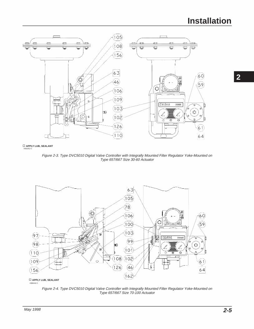
657 and 667 Actuators Unless otherwise noted, refer to figures 2-3 and 2-4for key number locations.
WARNING
To avoid personal injury due to thesudden uncontrolled movement ofparts, do not loosen the stem connec-tor cap screws on a Type 667 actuatorwhen the stem connector has springforce applied to it. Apply enoughpressure to lift the plug off the seatbefore loosening the stem connectorcap screws.
1. Isolate the control valve from the process linepressure, release pressure from both sides of thevalve body, and drain the process media from bothsides of the valve. Shut off all pressure lines to theactuator, releasing all pressure from the actuator. Uselock-out procedures to be sure that the abovemeasures stay in effect while you work on theequipment.
2. Attach the connector arm (key 108) to the valvestem connector.
3. Attach the mounting bracket (key 107) to the digitalvalve controller housing with screws (key 104).
2
Installation
May 1998 2-5
Figure 2-3. Type DVC5010 Digital Valve Controller with Integrally Mounted Filter Regulator Yoke-Mounted onType 657/667 Size 30-60 Actuator
44B1852-C APPLY LUB, SEALANT
Figure 2-4. Type DVC5010 Digital Valve Controller with Integrally Mounted Filter Regulator Yoke-Mounted onType 657/667 Size 70-100 Actuator
43B8442-C
APPLY LUB, SEALANT
2

DVC5000 Series
May 19982-6
Figure 2-5. Type DVC5010 Digital Valve Controller with Integrally Mounted Filter Regulator Yoke-Mounted onType 1250 Actuator
APPLY LUB, SEALANT43B8452-B / DOC
4. If valve travel exceeds 2 inches, a feedback armextension (key 97) is required. Remove the bias spring(key 78) for up to 2-inch travel from the feedback arm(key 79, figure 10-1). Attach the bias spring (key 78)for up to 4-inch travel to the feedback arm extension.Attach the feedback arm extension to the feedbackarm with screw (key 98), screw (key 99), spacer (key101), lock washers (key 162), and hex nuts (key 100).Remove the pipe plug (key 61) from the outputconnection on the back of the housing, apply sealant(key 64), and reinstall in the output connection on theside of the housing.
5. Loosely install a hex flange screw (key 105) in theright hole of the lower actuator mounting boss.
6. Position the digital valve controller so the hole inthe mounting pad of the mounting bracket goes ontothe mounting screw (key 105). Slide the digital valvecontroller to the left to expose the left hole. Install theleft screw (key 105). Tighten both screws (key 105).
NoteThe alignment pin (key 46) is stored insidethe digital valve controller housing. It islocated above the supply pressure gauge.
7. Set the position of the feedback arm (key 79, figure10-1) on the digital valve controller by inserting the
alignment pin (key 46) through the hole on thefeedback arm marked ‘‘A’’ for Type 667 actuators orthe slot marked ‘‘B’’ for Type 657 actuators.
8. Apply lubricant (key 63) to the pin of the adjustmentarm (key 106). Place the pin into the slot of thefeedback arm (key 79) so that the bias spring loadsthe pin against the side of the arm with the valve travelmarkings.
9. Install the external lock washer (key 110) on theadjustment arm. Position the adjustment arm in theslot of the connector arm (key 108) and loosely installthe washer (key 126) and screw (key 109).
10. Slide the adjustment arm pin in the slot of theconnector arm until the pin is in line with the desiredvalve travel marking. Tighten the screw (key 109).
11. Remove the alignment pin (key 46) and store it inthe module base next to the I/P assembly.
12. Attach the shield (key 102) with two screws (key103). On Type 657 or 667 size 70-100 actuators, startthe screws before installing the shield.
1250 and 1250R Actuators Unless otherwise noted, refer to figure 2-5 for keynumber locations.
1. Isolate the control valve from the process linepressure, release pressure from both sides of thevalve body, and drain the process media from bothsides of the valve. Shut off all pressure lines to theactuator, releasing all pressure from the actuator. Uselock-out procedures to be sure that the abovemeasures stay in effect while you work on theequipment.
2

Installation
May 1998 2-7
Figure 2-6. Type DVC5010 Digital Valve Controller Mounted on a Type 529 or Baumann Size 32, 54, or 70 Actuator27B6719 / DOC
SPACER
CAP SCREW, FLANGED
CAP SCREW
MOUNTING BRACKET
LOCK WASHER
HEX NUT
CONNECTOR ARM
ADJUSTMENT ARM
CAP SCREW
MACHINE SCREW
PLAIN WASHER
LOCK WASHER
2. Attach the connector arm (key 108) to the valvestem connector.
3. Attach the mounting bracket (key 107) to thehousing (key 1) with screws (key 104).
4. Loosely attach the mounting bracket (key 107) tothe leg post with U-bolts (key 114), washers (key 127),and hex nuts (key 115). Position the digital valvecontroller vertically so that the terminal box clears thediaphragm casing of the actuator. Tighten the hexnuts, securing the mounting bracket to the leg post.
NoteThe alignment pin (key 46) is stored insidethe digital valve controller housing. It islocated above the supply pressure gauge.
5. Set the position of the feedback arm (key 79, figure10-1) on the digital valve controller by inserting thealignment pin (key 46) through the hole on thefeedback arm marked ‘‘A’’ for Type 1250R actuatorsor the slot marked ‘‘B’’ for Type 1250 actuators.
6. Apply lubricant (key 63) to the pin of the adjustmentarm (key 106). Place the pin into the slot of thefeedback arm (key 79) so that the bias spring loadsthe pin against the side of the arm with the valve travelmarkings.
7. Install the external lock washer (key 110) on theadjustment arm. Position the adjustment arm in theslot of the connector arm (key 108) and loosely installthe washer (key 126) and screw (key 109).
8. Loosely attach the brace (key 111) to the mountingbracket (key 107) with screws (key 112), washers (key123), and hex nuts (key 115). Attach the brace (key111) to the leg post with U-bolts (key 114), washers(key 127), and hex nuts (key 115). Tighten the screwsand hex nuts (keys 112 and 115).
9. Slide the adjustment arm pin in the slot of theconnector arm until the pin is in line with the desiredvalve travel marking. Tighten the screw (key 109).
10. Remove the alignment pin (key 46) and store inthe module base next to the I/P assembly.
11. Attach the shield (key 102) with two screws (key103).
Mounting Type DVC5010 on OtherSliding-Stem Actuators
529 and Baumann Size 32, 54, and 70Actuators Refer to figure 2-6 for parts locations.
1. Isolate the control valve from the process linepressure, release pressure from both sides of thevalve body, and drain the process media from bothsides of the valve. Shut off all pressure lines to thepneumatic actuator, releasing all pressure from theactuator. Use lock-out procedures to be sure that the
2
DVC5000 Series
May 19982-8
above measures stay in effect while working on theequipment.
2. If necessary, remount the actuator on the valve sothat the pipeline will be perpendicular to the yoke legsto provide clearance for the digital valve controller.
3. Loosen the lower locknut on the valve stem. Slipthe connector arm between the locknuts. Tighten thelower locknut against the connector arm.
4. Attach the mounting bracket to the digital valvecontroller with three cap screws.
5. Position the digital valve controller so the top holein the mounting bracket mounting pad aligns with thethreaded hole in the yoke mounting boss. Start theflanged cap screw with washer in the yoke boss. Donot tighten.
6. Position the digital valve controller so the bottomhole in the mounting bracket mounting pad aligns withthe through hole in the yoke leg.
7. Position the spacer between the mounting bracketand yoke leg, then insert the cap screw through themounting bracket, spacer and yoke leg.
8. Secure the assembly with the washer and hex nut.Align the digital valve controller with the actuator yokeand tighten the hex nut. Tighten the cap screw in themounting bracket top hole.
NoteThe alignment pin (key 46) is stored insidethe digital valve controller housing. It islocated above the supply pressure gauge.
9. Set the position of the feedback arm (key 79, figure10-1) on the digital valve controller by inserting thealignment pin (key 46) through the hole on thefeedback arm marked ‘‘A’’ for fail-closed actuators orthe slot marked ‘‘B’’ for fail-open actuators.
10. Apply lubricant to the adjustment arm pin. Placethe pin into the slot of the feedback arm (key 79) sothat the bias spring loads the pin against the side ofthe arm with the valve travel markings.
11. As shown in figure 2-6, loosely fasten theadjustment arm to the connector arm with a machinescrew, washer and lock washer.
12. Slide the adjustment arm pin in the slot of theconnector arm until the pin is in line with the desiredvalve travel marking. Tighten the machine screw.
13. Remove the alignment pin (key 46) and store it inthe module base next to the I/P assembly.
Gulde Actuators Refer to figure 2-7 for parts locations.
1. Isolate the control valve from the process linepressure, release pressure from both sides of thevalve body, and drain the process media from bothsides of the valve. Shut off all pressure lines to thepneumatic actuator, releasing all pressure from theactuator. Use lock-out procedures to be sure that theabove measures stay in effect while working on theequipment.
2. Attach the connector arm to the valve stemconnector.
3. Attach the mounting bracket to the instrumenthousing.
4. Loosely attach the mounting bracket to the actuatorleg with U-bolts, washers, and hex nuts. Position thedigital valve controller vertically so that the terminalbox clears the diaphragm casing of the actuator.Tighten the hex nuts, securing the mounting bracket tothe actuator leg.
NoteThe alignment pin (key 46) is stored insidethe digital valve controller housing. It islocated above the supply pressure gauge.
5. Set the position of the feedback arm (key 79, figure10-1) on the digital valve controller by inserting thealignment pin (key 46) through the hole on thefeedback arm marked ‘‘A’’ for a Po operating mode (airopens) or the slot marked ‘‘B’’ for Ps (air closes).
6. Apply lubricant to the pin of the adjustment arm.Place the pin into the slot of the feedback arm (key 79,figure 10-1) so that the bias spring loads the pinagainst the side of the arm with the valve travelmarkings.
7. Install the external lock washer on the adjustmentarm. Position the adjustment arm in the slot of theconnector arm and loosely install the washer andscrew.
8. Loosely attach the brace to the mounting bracketwith screws, washers, and hex nuts. Attach the braceto the actuator leg with U-bolts, washers, and hexnuts. Tighten the screws and hex nuts.
9. Slide the adjustment arm pin in the slot of theconnector arm until the pin is in line with the desired
2

Installation
May 1998 2-9
Figure 2-7. Type DVC5010 Digital Valve Controller with Integrally Mounted Filter Regulator Yoke-Mounted onGulde Pneumatic Actuator Model GA
CONNECTOR ARM
MOUNTINGBRACKET
ADJUSTMENT ARM
BRACE
SHIELD
A7020 / IL
valve travel marking. Tighten the screw on theadjustment arm.
10. Remove the alignment pin (key 46) and store inthe module base next to the I/P assembly.
11. Attach the shield with two screws.
Mounting Type DVC5020 on FisherRotary Actuators
1051 and 1052 Actuators Unless otherwise noted, refer to figure 2-8 or 2-9 forkey number locations.
1. Isolate the control valve from the process linepressure, release pressure from both sides of thevalve body, and drain the process media from bothsides of the valve. Shut off all pressure lines to thepneumatic actuator, releasing all pressure from theactuator. Use lock-out procedures to be sure that theabove measures stay in effect while working on theequipment.
NoteGo to step 12 if the actuator already hasthe cam (key 94) installed.
2. Mark the positions of the travel indicator andactuator cover. Then, remove the actuator travelindicator machine screws, travel indicator, andactuator cover cap screws.
3. Remove the cover plate from the actuator housing.
NoteFor information on the various actuatormounting styles and positions, refer to theappropriate actuator instruction manual.
4. For actuator mounting styles A and D, proceed tothe note before step 8. For actuator mounting styles Band C, continue with step 5.
2
DVC5000 Series
May 19982-10
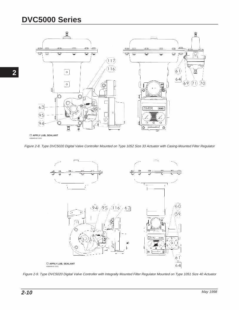
Figure 2-8. Type DVC5020 Digital Valve Controller Mounted on Type 1052 Size 33 Actuator with Casing-Mounted Filter Regulator
APPLY LUB, SEALANT43B8450-B / DOC
Figure 2-9. Type DVC5020 Digital Valve Controller with Integrally Mounted Filter Regulator Mounted on Type 1051 Size 40 Actuator
APPLY LUB, SEALANT43B8448-B / DOC
2
Installation
May 1998 2-11
5. Disconnect the actuator turnbuckle from the leverarm.
NoteDo not change the position of the rod endbearing on the end of the turnbuckle.
6. Loosen the lever clamping bolt in the lever.
7. Mark the lever/valve shaft orientation, and removethe lever.
NoteLinear Cam—Cam A has the letter D(direct acting) on one side and the letter R(reverse acting) on the other side. Alwaysinstall cam A with the letter D on the sameside as the cam mounting screw heads(key 95).
8. Install the cam (key 94) on the actuator lever withthe cam mounting screws (key 95).
9. For actuator styles A and D, proceed to step 12.For actuator styles B and C, continue with step 10.
10. Slide the lever/cam assembly (cam side first) ontothe valve shaft. Orient the lever with the shaft as notedin step 7, and tighten the lever clamping bolt.
NoteRefer to the appropriate actuatorinstruction manual to determine thedistance required between the housingface and the lever face and to determinethe proper tightening torque for the leverclamping bolt.
11. Connect the turnbuckle and the lever arm.
12. For Type 1051 size 33 and 1052 size 20 and 33actuators, attach an adaptor (key 117) to the actuatorwith four screws (key 116). Then assemble the digitalvalve controller assembly to the adaptor. The roller onthe digital valve controller feedback arm will contactthe actuator cam as it is being attached. Install andtighten four screws (key 116).
For other size 1051 and 1052 actuators, assemblethe digital valve controller assembly to the frontaccess opening of the actuator. The roller on thedigital valve controller feedback arm will contact theactuator cam as it is being attached. Install and tightenfour screws (key 116).
13. Replace the actuator cover and the travelindicator in the positions that were marked in step 2.
NoteActuator cover alignment on the Type 1052actuator can be aided by moving theactuator slightly away from its up travelstop using a regulated air source. If holealignment cannot be obtained in thismanner, temporarily loosen the capscrews that secure the housing to themounting yoke, and shift the housingslightly. Do not completely stroke theactuator while the cover is removed.
Mounting Type DVC5020 on FisherSliding-Stem Actuators
471 Actuators Mounting the Type DVC5020 digital valve controllerrequires an actuator with a tapped lower yoke boss.Refer to figure 2-10 for parts location. Also refer to PSSheet 62.1:FIELDVUE(B) Mounting FIELDVUEInstruments on Piston Actuators for guidelines onusing the digital valve controller with the FairchildModel 25463 reversing relay.
1. Isolate the control valve from the process linepressure, release pressure from both sides of thevalve body, and drain the process media from bothsides of the valve. Shut off all pressure lines to thepneumatic actuator, releasing all pressure from theactuator. Use lock-out procedures to be sure that theabove measures stay in effect while working on theequipment.
2

DVC5000 Series
May 19982-12
Figure 2-10. Type DVC5020 Digital Valve Controller with a Fairchild Model 25463 Relay Mounted on a 471 Size 100 Actuator.
PLAIN WASHER
HEX NUT
STUD, CONT THREAD
A LOCK WASHER
CAP SCREW
MOUNTING PLATE
CAP SCREW, HEXSOCKET
MOUNTING BRACKET
VENT
PLAIN WASHER
HEX NUT
STUD, CONT THREADA
SPACER
NIPPLE
NIPPLE
TEE
BUSHING
BUSHINGBUSHING
FAIRCHILD MODEL 25463
SECTION A-A
CAM
PIPEPLUG
SPACER
27B6708-A / DOC
WARNING
To avoid personal injury or propertydamage, in the following step do notloosen the stem connector capscrews when the stem connector hasspring or loading pressure force ap-plied to it.
2. Remove one of the stem connector cap screws andreplace with the continuous thread stud. Thread thestud through the stem connector far enough to permitscrewing a washer and hex nut onto the stud.
3. Place a washer and hex nut on the stud and tightenagainst the stem connector.
In steps 4 through 7 hold the two halves of the stemconnector together, until the cam is fastened in place,to keep the valve stem and the actuator piston rodfrom separating.
4. Remove the second stem connector cap screw andreplace with the continuous thread stud. Thread thestud through the stem connector far enough to permitscrewing a washer and hex nut onto the stud.
5. Place a washer and hex nut on the stud and tightenagainst the stem connector.
6. Place a spacer on each of the studs extending fromthe stem connector.
7. Place the cam on the studs as shown in figure2-10. Be sure the stem connector is still clamping theactuator piston rod and valve stem. Fasten thespacers and cam in place with two washers and hexnuts.
8. To mount the digital valve controller requires atapped lower yoke boss. Screw the continuous threadstud into the tapped hole in the lower yoke boss.
9. Fasten the mounting plate to the actuator upperyoke boss with two cap screws and lock washers, andto the lower yoke boss with a washer and hex nut.
The mounting parts kit for the Type 471 actuatorcontains a mounting bracket with tapped holes for apipe plug and vent. Steps 10 through 15 describe howto replace the existing mounting bracket on the digitalvalve controller with the mounting bracket from theparts kit and how to transfer the feedback parts fromthe existing mounting bracket to the mounting bracketin the kit. In the following step, refer to figure 10-2 forkey number locations.
10. On the digital valve controller, disconnect the biasspring (key 82) from the arm assembly (key 91).Remove the mounting bracket (key 74) from the backof the digital valve controller.
11. On the mounting bracket just removed, note theorientation of the feedback parts, then remove the
2
Installation
May 1998 2-13
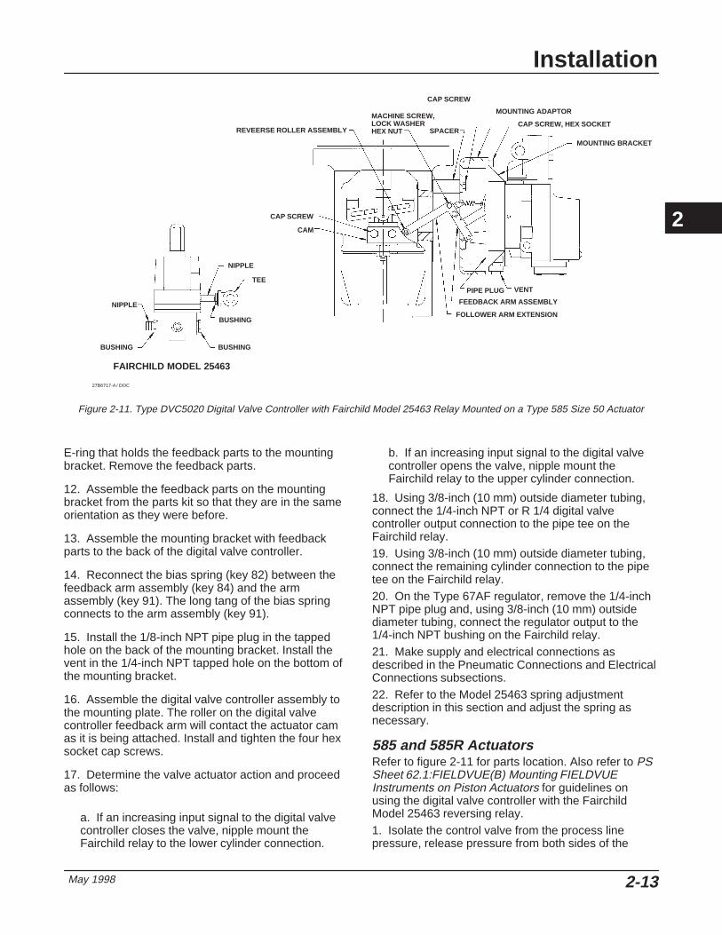
Figure 2-11. Type DVC5020 Digital Valve Controller with Fairchild Model 25463 Relay Mounted on a Type 585 Size 50 Actuator
27B6717-A / DOC
BUSHING
BUSHING
TEE
NIPPLE
NIPPLE
BUSHING
REVEERSE ROLLER ASSEMBLY
CAP SCREW
CAM
MACHINE SCREW,LOCK WASHERHEX NUT SPACER
CAP SCREW
MOUNTING ADAPTOR
CAP SCREW, HEX SOCKET
MOUNTING BRACKET
PIPE PLUG VENT
FEEDBACK ARM ASSEMBLY
FOLLOWER ARM EXTENSION
FAIRCHILD MODEL 25463
E-ring that holds the feedback parts to the mountingbracket. Remove the feedback parts.
12. Assemble the feedback parts on the mountingbracket from the parts kit so that they are in the sameorientation as they were before.
13. Assemble the mounting bracket with feedbackparts to the back of the digital valve controller.
14. Reconnect the bias spring (key 82) between thefeedback arm assembly (key 84) and the armassembly (key 91). The long tang of the bias springconnects to the arm assembly (key 91).
15. Install the 1/8-inch NPT pipe plug in the tappedhole on the back of the mounting bracket. Install thevent in the 1/4-inch NPT tapped hole on the bottom ofthe mounting bracket.
16. Assemble the digital valve controller assembly tothe mounting plate. The roller on the digital valvecontroller feedback arm will contact the actuator camas it is being attached. Install and tighten the four hexsocket cap screws.
17. Determine the valve actuator action and proceedas follows:
a. If an increasing input signal to the digital valvecontroller closes the valve, nipple mount theFairchild relay to the lower cylinder connection.
b. If an increasing input signal to the digital valvecontroller opens the valve, nipple mount theFairchild relay to the upper cylinder connection.
18. Using 3/8-inch (10 mm) outside diameter tubing,connect the 1/4-inch NPT or R 1/4 digital valvecontroller output connection to the pipe tee on theFairchild relay.19. Using 3/8-inch (10 mm) outside diameter tubing,connect the remaining cylinder connection to the pipetee on the Fairchild relay.20. On the Type 67AF regulator, remove the 1/4-inchNPT pipe plug and, using 3/8-inch (10 mm) outsidediameter tubing, connect the regulator output to the1/4-inch NPT bushing on the Fairchild relay.21. Make supply and electrical connections asdescribed in the Pneumatic Connections and ElectricalConnections subsections.22. Refer to the Model 25463 spring adjustmentdescription in this section and adjust the spring asnecessary.
585 and 585R Actuators Refer to figure 2-11 for parts location. Also refer to PSSheet 62.1:FIELDVUE(B) Mounting FIELDVUEInstruments on Piston Actuators for guidelines onusing the digital valve controller with the FairchildModel 25463 reversing relay.1. Isolate the control valve from the process linepressure, release pressure from both sides of the
2

DVC5000 Series
May 19982-14
valve body, and drain the process media from bothsides of the valve. Shut off all pressure lines to thepneumatic actuator, releasing all pressure from theactuator. Use lock-out procedures to be sure that theabove measures stay in effect while working on theequipment.
The mounting parts kit for the Type 585 actuatorcontains a mounting bracket with tapped holes for apipe plug and vent. Steps 2 through 10 describe howto replace the existing mounting bracket on the digitalvalve controller with the mounting bracket from theparts kit and how to transfer the feedback parts fromthe existing mounting bracket to the mounting bracketin the kit. In the following step, refer to figure 10-2 forkey number locations.
2. On the digital valve controller, disconnect the biasspring (key 82) from the arm assembly (key 91).Remove the mounting bracket (key 74) from the backof the digital valve controller.
3. On the mounting bracket just removed, note theorientation of the feedback parts, then remove theE-ring that holds the feedback parts to the mountingbracket. Remove the feedback parts.
4. Assemble the feedback parts on the mountingbracket from the parts kit so that they are in the sameorientation as they were before.
5. Remove the follower post (key 87) from thefeedback arm assembly (key 84).
6. Attach the follower arm extension to the feedbackarm assembly with two machine screws, lock washers,and hex nuts as shown in figure 2-11.
7. Attach the follower post to the follower armextension so that it is on the left side of the followerarm extension when viewing the back of the digitalvalve controller.
8. Assemble the mounting bracket with feedbackparts to the back of the digital valve controller.
9. Reconnect the bias spring (key 82) between thefeedback arm assembly (key 84) and the armassembly (key 91). The long tang of the bias springconnects to the arm assembly (key 91).
10. Install the pipe plug in the tapped hole on the backof the mounting bracket. Install the vent in the tappedhole on the bottom of the mounting bracket.
In step 11, refer to the actuator instruction manual forkey number locations, unless noted otherwise.
11. Loosen eight screws, and remove the front andback yoke covers (keys 18 and 20).
12. Loosen four screws, and remove the actuatorblanking plate.
13. Insert the cap screws through the mountingadaptor as shown in figure 2-11. Place spacers on thecap screws.
14. Fasten the mounting adaptor to the actuator yoke.Tighten the cap screws.
In the next step hold the two halves of the stemconnector together, until the cam is fastened in place,to keep the valve stem and the actuator piston rodfrom separating.
15. Remove the two cap screws from the stemconnector and attach the cam as shown in figure 2-11.
16. Assemble the digital valve controller assembly tothe mounting adaptor. The roller on the digital valvecontroller feedback arm will contact the actuator camas it is being attached. Install and tighten the four capscrews.
17. Determine the valve actuator action and proceedas follows:
c. If an increasing input signal to the digital valvecontroller closes the valve, nipple mount theFairchild relay to the lower cylinder connection.
d. If an increasing input signal to the digital valvecontroller opens the valve, nipple mount theFairchild relay to the upper cylinder connection.
18. Using 3/8-inch (10 mm) outside diameter tubing,connect the 1/4-inch NPT or R 1/4 digital valvecontroller output connection to the pipe tee on theFairchild relay.
19. Using 3/8-inch (10 mm) outside diameter tubing,connect the remaining cylinder connection to the pipetee on the Fairchild relay.
20. On the Type 67AF regulator, remove the 1/4-inchNPT pipe plug and, using 3/8-inch (10 mm) outsidediameter tubing, connect the regulator output to the1/4-inch NPT bushing on the Fairchild relay.
21. Replace the actuator front and back yoke covers.Discard the actuator blanking plate and four screws
22. Make supply and electrical connections asdescribed in the Pneumatic Connections and ElectricalConnections subsections.
23. Refer to Model 25463 spring adjustmentdescription in this section and adjust the spring asnecessary.
Fairchild Model 25463 Reversing RelaySpring Adjustment The Fairchild Model 25463 is a spring biased reversingrelay. It provides an output pressure which follows theequation Po = K – Ps. Where Po is the output pressure,K is the spring bias and Ps is the signal pressure. Thespring bias is adjusted during calibration as follows:
2
Installation
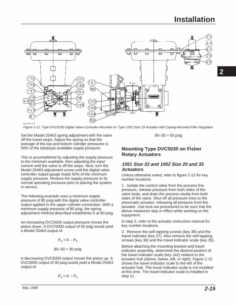
May 1998 2-15
Figure 2-12. Type DVC5030 Digital Valve Controller Mounted on Type 1052 Size 33 Actuator with Casing-Mounted Filter Regulator
A
54B7195-B / DOC
A
Set the Model 25463 spring adjustment with the valveoff the travel stops. Adjust the spring so that theaverage of the top and bottom cylinder pressures is50% of the minimum available supply pressure.
This is accomplished by adjusting the supply pressureto the minimum available, then adjusting the inputcurrent until the valve is off the stops. Next, turn theModel 25463 adjustment screw until the digital valvecontroller output gauge reads 50% of the minimumsupply pressure. Restore the supply pressure to itsnormal operating pressure prior to placing the systemin service.
The following example uses a minimum supplypressure of 80 psig with the digital valve controlleroutput applied to the upper cylinder connection. With aminimum supply pressure of 80 psig, the springadjustment method described establishes K at 80 psig.
An increasing DVC5000 output pressure moves thepiston down. A DVC5000 output of 50 psig would yielda Model 25463 output of
Po = K – Ps
80–50 = 30 psig
A decreasing DVC5000 output moves the piston up. ADVC5000 output of 30 psig would yield a Model 25463output of
Po = K – Ps
80–30 = 50 psig
Mounting Type DVC5030 on FisherRotary Actuators
1051 Size 33 and 1052 Size 20 and 33Actuators Unless otherwise noted, refer to figure 2-12 for keynumber locations.
1. Isolate the control valve from the process linepressure, release pressure from both sides of thevalve body, and drain the process media from bothsides of the valve. Shut off all pressure lines to thepneumatic actuator, releasing all pressure from theactuator. Use lock-out procedures to be sure that theabove measures stay in effect while working on theequipment.
In step 2, refer to the actuator instruction manual forkey number locations.
2. Remove the self-tapping screws (key 38) and thetravel indicator (key 37). Also remove the self-tappingscrews (key 36) and the travel indicator scale (key 35).
Before attaching the mounting bracket and travelindicator assembly, determine the desired position ofthe travel indicator scale (key 142) relative to theactuator hub (above, below, left, or right). Figure 2-12shows the travel indicator scale to the left of theactuator hub. The travel indicator scale is not installedat this time. The travel indicator scale is installed instep 11.
2

DVC5000 Series
May 19982-16
3. Position the mounting bracket (key 107) so that thetravel indicator scale (key 142) will be in the desiredposition. The travel indicator scale is not installed atthis time; it is installed in step 11.
4. Attach the mounting bracket (key 107) to theactuator using four hex head cap screws (key 191)and washers (key 140).
5. Place the spacer (key 141) on the actuator hub.
6. Attach the travel indicator assembly (key 144) tothe spacer as follows:
a. If the valve is open without pressure to theactuator [push-down-to-close (PDTC) actuatormounting], position the assembly so that thepointer on the travel indicator assembly will be overthe open mark on the travel scale. Attach the travelindicator assembly (key 144) and spacer (key 141)to the actuator hub using two machine screws (key145). For size 33 actuators only, also include twowashers (key 199), as shown in figure 2-12.
b. If the valve is closed without pressure to theactuator [push-down-to-open (PDTO) actuatormounting], position the assembly so that thepointer on the travel indicator assembly will be overthe closed mark on the travel scale. Attach thetravel indicator assembly (key 144) and spacer (key141) to the actuator hub using two machine screws(key 145). For size 33 actuators only, also includetwo washers (key 199), as shown in figure 2-12.
7. Position the feedback arm (key 79, figure 10-3) sothat, when the digital valve controller is mounted onthe actuator, the pin on the travel indicator assembly(key 144) will slide into the slot on the feedback arm.
8. Apply lubricant (key 63) to the travel indicatorassembly pin (key 144).
9. Position the digital valve controller on the mountingbracket (key 107). Be sure the pin on the travelindicator assembly (key 144) is in the feedback armslot such that the bias spring (key 78) loads the pinagainst the side of the slot marked with an X.
10. Attach the digital valve controller to the mountingbracket (key 107) using four hex head cap screws(key 104).
11. Attach the travel indicator scale (key 142) to themounting bracket (key 107) with two washers (key198) and hex nuts (key 197). Position the scale so thatthe OPEN or CLOSED mark is beneath the travelindicator pointer (key 144) and tighten the hex nuts.
1051 Size 30 to 60 and 1052 Size 40 to 70Actuators Unless otherwise noted, refer to figure 2-12 for keynumber locations.
1. Isolate the control valve from the process linepressure, release pressure from both sides of thevalve body, and drain the process media from bothsides of the valve. Shut off all pressure lines to thepneumatic actuator, releasing all pressure from theactuator. Use lock-out procedures to be sure that theabove measures stay in effect while working on theequipment.
In steps 2 and 3, refer to the actuator instructionmanual for key number locations.
2. Remove the self-tapping screws (key 38) and thetravel indicator (key 37). Also remove self-tappingscrews (key 36) and the travel indicator scale (key 35).
3. Remove the four hex head cap screws (key 34)and washers (key 63) that secure the actuator cover(key 33). Do not remove the cover. Set aside thescrews and washers for later use.
Before attaching the travel indicator assembly,determine the desired position of the travel indicatorscale (key 142) relative to the actuator hub (above,below, left, or right). Figure 2-12 shows the travelindicator scale to the left of the actuator hub. Thetravel indicator scale is not installed at this time. Thetravel indicator scale is installed in step 11.
4. Attach the travel indicator assembly (key 144) tothe spacer as follows:
a. If the valve is open without pressure to theactuator [push-down-to-close (PDTC) actuatormounting], position the assembly so that thepointer on the travel indicator assembly will be overthe open mark on the travel scale. Attach the travelindicator assembly (key 144) to the actuator hubusing two machine screws (key 145).
b. If the valve is closed without pressure to theactuator [push-down-to-open (PDTO) actuatormounting], position the assembly so that thepointer on the travel indicator assembly will be overthe closed mark on the travel scale. Attach thetravel indicator assembly (key 144) to the actuatorhub using two machine screws (key 145).
5. Attach the digital valve controller to the mountingbracket assembly (key 107) using four hex head capscrews (key 104).
6. Position the feedback arm (key 79, figure 10-3) sothat, when the digital valve controller is mounted onthe actuator, the pin on the travel indicator assembly(key 144) will slide into the slot on the feedback arm.
7. Apply lubricant (key 63) to the travel indicatorassembly pin (key 144).
8. Position the mounting bracket (key 107), withcontroller, so that the travel indicator scale (key 142)will be in the desired position. The travel indicatorscale is not installed at this time; it is installed in step11.
2

Installation
May 1998 2-17
9. Be sure the pin on the travel indicator assembly(key 144) is in the feedback arm slot such that the biasspring (key 78) loads the pin against the side of theslot marked with an X.
10. Attach the mounting bracket to the actuator usingthe four hex head screws (key 34) and washers (key63) removed in step 3.
11. Attach the travel indicator scale (key 142) to themounting bracket (key 107) with two washers (key198) and hex nuts (key 197). Position the scale so thatthe OPEN or CLOSED mark is beneath the travelindicator pointer (key 144) and tighten the hex nuts.
1066SR Sizes 20, 27, and 75 Actuators Unless otherwise noted, refer to figure 2-12 for keynumber locations.
1. Isolate the control valve from the process linepressure, release pressure from both sides of thevalve body, and drain the process media from bothsides of the valve. Shut off all pressure lines to thepneumatic actuator, releasing all pressure from theactuator. Use lock-out procedures to be sure that theabove measures stay in effect while working on theequipment.
In steps 2 and 3, refer to the actuator instructionmanual for key number locations.
2. Remove the machine screws (key 24) and thetravel indicator (key 22).
3. Remove the travel indicator scale (key 21) byremoving the four cap screws (key 20). Set aside thescrews for later use.
Before attaching the mounting bracket and travelindicator assembly, determine the desired position ofthe travel indicator scale (key 142) relative to theactuator hub (above, below, left, or right). Figure 2-12shows the travel indicator scale to the left of theactuator hub. The travel indicator scale is not installedat this time. The travel indicator scale is installed instep 12.
4. Position the mounting bracket (key 107) so that thetravel indicator scale (key 142) will be in the desiredposition. The travel indicator scale is not installed atthis time; it is installed in step 12.
5. Attach the mounting bracket (key 107) to theactuator using washers (key 140) and the four capscrews removed in step 3.
6. Place the spacer (key 141) on the actuator hub.
7. Attach the travel indicator assembly (key 144) tothe spacer as follows:
a. If the valve is open without pressure to theactuator [push-down-to-close (PDTC) actuator
mounting], position the assembly so that thepointer on the travel indicator assembly will be overthe open mark on the travel scale. Attach the travelindicator assembly (key 144) and spacer (key 141)to the actuator hub using two machine screws (key145) and washers (key 199). The washers are notrequired for size 75 actuators.
b. If the valve is closed without pressure to theactuator [push-down-to-open (PDTO) actuatormounting], position the assembly so that thepointer on the travel indicator assembly will be overthe closed mark on the travel scale. Attach thetravel indicator assembly (key 144) and spacer (key141) to the actuator hub using two machine screws(key 145) and washers (key 199). The washers arenot required for size 75 actuators.
8. Position the feedback arm (key 79, figure 10-3) sothat, when the digital valve controller is mounted onthe actuator, the pin on the travel indicator assembly(key 144) will slide into the slot on the feedback arm.
9. Apply lubricant (key 63) to the travel indicatorassembly pin (key 144).
10. Position the digital valve controller on themounting bracket (key 107). Be sure the pin on thetravel indicator assembly (key 144) is in the feedbackarm slot such that the bias spring (key 78) loads thepin against the side of the slot marked with an X.
11. Attach the digital valve controller to the mountingbracket (key 107) using four hex head cap screws(key 104).
12. Attach the travel indicator scale (key 142) to themounting bracket (key 107) with two washers (key198) and hex nuts (key 197). Position the scale so thatthe OPEN or CLOSED mark is beneath the travelindicator pointer (key 144) and tighten the hex nuts.
Mounting Type DVC5030 to ReplacePositioners
Replacing Masoneilan Type 4600Positioners Unless otherwise noted, refer to figure 2-13 for keynumber locations.
1. Isolate the control valve from the process linepressure, release pressure from both sides of thevalve body, and drain the process media from bothsides of the valve. Shut off all pressure lines to thepneumatic actuator, releasing all pressure from theactuator. Use lock-out procedures to be sure that theabove measures stay in effect while working on theequipment.
2. Using a 3/16-inch hex wrench, remove the existinghub from the actuator shaft.
2

DVC5000 Series
May 19982-18
Figure 2-13. Type DVC5030 Digital Valve Controller Assembly for Replacing a Masoneilan Type 4600 Positioner
A
A
47B2824-B / DOC
SECTION A-A
3. Attach the shaft connector (key 179) to the actuatorshaft using the socket head cap screw (key 185).
4. Attach the shaft connector cap assembly (key 181)to the shaft connector using two machine screws (key188).
5. Attach the emulator (key 177) to the actuator usingtwo socket head cap screws (key 186).
The digital valve controller can mount to the actuatorin any one of four possible mounting quadrants.Determine the desired mounting position then proceedwith the next step.
6. Attach the positioner plate (key 178) to theemulator using the three spacers (key 182) andflathead cap screws (key 184).
7. On the Type DVC5030 digital valve controller,remove the feedback arm (key 79, figure 10-3) andslip the coupler (key 180) on the travel sensor shaft.Tighten the coupler set screw to secure the coupler onthe travel sensor shaft.
8. Align the digital valve controller with the mountingholes in the positioner plate (key 178). Be sure thecoupler slips onto the pin in the shaft connector capassembly (key 181). Secure the controller to thepositioner plate using four hex head cap screws (key187). Leave the coupler loose on the connector capassembly (key 181) until travel sensor adjustment iscomplete.
9. Perform the Travel Sensor Adjust procedure in the“Calibration” section, Section 6.
Replacing Neles-Jamesbury Type NE600,NP600, NE700 and NP700 Positioners Unless otherwise noted, refer to figure 2-14 for keynumber locations.
1. Isolate the control valve from the process linepressure, release pressure from both sides of thevalve body, and drain the process media from bothsides of the valve. Shut off all pressure lines to thepneumatic actuator, releasing all pressure from theactuator. Use lock-out procedures to be sure that theabove measures stay in effect while working on theequipment.
2. Attach the emulator (key 177) to the actuator usingthree socket head cap screws (key 189).
3. Position the tie-bar assembly (key 190) in theactuator shaft slot so that it is approximately centered.Tighten the set screw to temporarily hold the tie-barassembly in place.
The digital valve controller can mount to the actuatorin any one of four possible mounting quadrants.Determine the desired mounting position then proceedwith the next step.
4. Attach the positioner plate (key 178) to theemulator using the three spacers (key 182) andflathead cap screws (key 184).
5. On the Type DVC5030 digital valve controller,remove the feedback arm (key 79, figure 10-3) andslip the coupler (key 180) on the travel sensor shaft.Tighten the coupler set screw to secure the coupler onthe travel sensor shaft.
6. Align the digital valve controller with the mountingholes in the positioner plate (key 178). Once thecoupler passes through the hole in the positioner
2

Installation
May 1998 2-19
Figure 2-14. Type DVC5030 Digital Valve Controller Assembly for Replacing Neles-Jamesbury Positioners
A
ASECTION A-A
47B2826-B / DOC
plate, place the valve position pointer (key 206) on thecoupler. Slide the pointer onto the coupler until it restson the controller housing. Position the pointer so that,during normal operation, it will not contact any of thespacers (key 182) when the actuator shaft rotates.
7. Be sure the coupler slips onto the pin in the tie-barassembly (key 190). If necessary, loosen the setscrew to allow the tie-bar assembly to slide in theactuator shaft slot. Secure the controller to thepositioner plate using four hex head cap screws (key187).
8. Rotate the coupler (key 180) to be sure it does notbind, then tighten the set screw to hold the tie-barassembly (key 190) in place. Leave the coupler looseon the tie-bar assembly (key 190) until the travelsensor adjustment is complete.
9. Perform the Travel Sensor Adjust procedure in the“Calibration” section, Section 6.
10. Determine the actuator action (clockwise shaftrotation opens the valve or clockwise shaft rotationcloses the valve) and select the appropriate indicatorscale (key 207). Remove the paper backing from theindicator scale to expose the adhesive.
11. Slip the indicator scale (key 207) under the pointerand fasten it to the emulator (key 177 by pressing thescale in place.
12. Position the pointer as follows:
a. If the valve is closed, position the pointer overthe CLOSED mark on the indicator scale.
b. If the valve is open, position the pointer over theOPEN mark on the indicator scale.
13. Be sure the pointer (key 206) does not contact theemulator (key 177) or digital valve controller housingand tighten the screw (key 205) to secure the pointeron the coupler (key 180).
Replacing PMV Model P1200, P1250, andP2000 Positioners Unless otherwise noted, refer to figure 2-15 for keynumber locations.
1. Isolate the control valve from the process linepressure, release pressure from both sides of thevalve body, and drain the process media from bothsides of the valve. Shut off all pressure lines to thepneumatic actuator, releasing all pressure from theactuator. Use lock-out procedures to be sure that theabove measures stay in effect while working on theequipment.
2. Remove the PMV positioner from the valve andremove the PMV spindle.
3. Machine the end of the spindle so that it matchesthe dimensions in figure 2-16.
4. Attach the emulator (key 177) to the actuator usingthree socket head cap screws (key 189).
The digital valve controller can mount to the actuatorin any one of four possible mounting quadrants.Determine the desired mounting position then proceedwith the next step.
5. Attach the positioner plate (key 178) to theemulator using the three spacers (key 182) andflathead cap screws (key 184).
2

DVC5000 Series
May 19982-20
Figure 2-15. Type DVC5030 Digital Valve Controller Assembly for Replacing PMV Positioners
A
ASECTION A-A
47A2828-C / DOC
Figure 2-16. PMV Spindle Dimensions Required to Fit Coupler(key 180)
17B4021–A / IL
EXISTING SHAFTDEPENDENT ONACTUATOR
SHAFTCONNECTOR TYPE 1200, 1500
& 2000 SERIESPMV SPINDLE
ADDITIONAL MACHINING REQUIRED
6. On the Type DVC5030 digital valve controller,remove the feedback arm (key 79, figure 10-3) andslip the coupler (key 180) on the travel sensor shaft.Tighten the coupler set screw to secure the coupler onthe travel sensor shaft.
7. Align the digital valve controller with the mountingholes in the positioner plate (key 178). Once thecoupler passes through the hole in the positionerplate, place the valve position pointer (key 206) on thecoupler. Slide the pointer onto the coupler until it restson the controller housing. Position the pointer so that,during normal operation, it will not contact any of thespacers (key 182) when the actuator shaft rotates.
8. Install the machined spindle into the coupler (key180) then slide the controller in until the spindleengages the actuator shaft.
9. Secure the controller to the positioner plate usingfour hex head cap screws (key 187). Leave thecoupler loose on the spindle until the travel sensoradjustment is complete.
10. Perform the Travel Sensor Adjust procedure inthe “Calibration” section, Section 6.
11. Determine the actuator action (clockwise shaftrotation opens the valve or clockwise shaft rotationcloses the valve) and select the appropriate indicatorscale (key 207). Remove the paper backing from theindicator scale to expose the adhesive.
12. Slip the indicator scale (key 207) under the pointerand fasten it to the emulator (key 177 by pressing thescale in place.
13. Position the pointer as follows:
a. If the valve is closed, position the pointer overthe CLOSED mark on the indicator scale.
b. If the valve is open, position the pointer over theOPEN mark on the indicator scale.
14. Be sure the pointer (key 206) does not contact theemulator (key 177) or digital valve controller housingand tighten the screw (key 205) to secure the pointeron the coupler (key 180).
Mounting Type DVC5040 on System9000 Actuators Refer to figures 2-17 and 10-4 for key numbers.
1. Isolate the control valve from the process linepressure, release pressure from both sides of thevalve body, and drain the process media from bothsides of the valve. Shut off all pressure lines to thepneumatic actuator, releasing all pressure from theactuator. Use lock-out procedures to be sure that theabove measures stay in effect while you work on theequipment.
2
Installation
May 1998 2-21
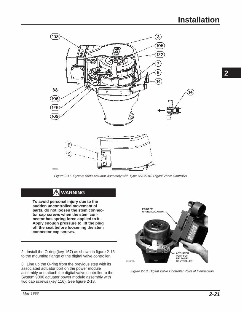
Figure 2-17. System 9000 Actuator Assembly with Type DVC5040 Digital Valve Controller
A6855/IL
WARNING
To avoid personal injury due to thesudden uncontrolled movement ofparts, do not loosen the stem connec-tor cap screws when the stem con-nector has spring force applied to it.Apply enough pressure to lift the plugoff the seat before loosening the stemconnector cap screws.
2. Install the O-ring (key 167) as shown in figure 2-18to the mounting flange of the digital valve controller.
3. Line up the O-ring from the previous step with itsassociated actuator port on the power moduleassembly and attach the digital valve controller to theSystem 9000 actuator power module assembly withtwo cap screws (key 116). See figure 2-18.
ACTUATORPORT FORFIELDVUE CONTROLLER
POINT ’A’O-RING LOCATION
Figure 2-18. Digital Valve Controller Point of Connection
W6510*A/IL
2

DVC5000 Series
May 19982-22
NoteThe alignment pin (key 46) is stored insidethe digital valve controller housing. It islocated above the supply pressure gauge.
4. Set the position of the adjustment arm (key 106) byinserting the alignment pin (key 46) through the holeon the feedback arm marked ‘‘A’’ for a fail-closedconfiguration or the hole marked ‘‘B’’ for fail-openconfigurations.
5. Apply lubricant (key 63) to the pin portion of theadjustment arm (key 106). Place the pin into the slot ofthe feedback arm (key 79) so that the bias springloads the pin against the side of the feedback arm withthe valve travel markings.
6. Loosely install the washer (key 126) and machinescrew (key 109) to attach the adjustment arm (key106) to the actuator feedback bracket (key 108).
7. Slide the adjustment arm pin in the slot of thefeedback arm until the pin is in line with the desiredvalve travel marking (see figure 2-19). Tighten themachine screw (key 109).
8. Remove the alignment pin (key 46) and store it inthe threaded hole near the top of the digital valvecontroller module base. Install the digital valvecontroller cover.
9. Install the System 9000 actuator cover assembly.
Mounting the Type 67AF Filter Regulator
A Type 67AF filter regulator, when used with theDVC5000 Series digital valve controllers, can bemounted three ways.
Integral-Mounted RegulatorRefer to figures 2-1 through 2-5 and figure 2-9.Lubricate an O-ring (key 60) and insert it in the recess
TravelMarkings
Inches (mm)
0.75(19)
| (32) 1.5 | 2
ActuatorTravel, Inches
0.75(1) 1.0 1.25 1.50 1.75 2.0
1. For travels less than 0.75 inches, use the 0.75 (19) travel mark.
around the SUPPLY connection on the digital valvecontroller. Attach the Type 67AF filter regulator to theside of the digital valve controller. This is the standardmethod of mounting the filter regulator.
Yoke-Mounted RegulatorMount the filter regulator with 2 screws (key 59) to thepre-drilled and tapped holes in the actuator yoke.Thread a 1/4-inch socket-head pipe plug (key 61) intothe unused outlet on the filter regulator. The O-ring(key 60) is not required.
Casing-Mounted RegulatorRefer to figures 2-8 and 2-12. Use the separate Type67AF filter regulator casing mounting bracket providedwith the filter regulator. Attach the mounting bracket tothe Type 67AF and then attach this assembly to theactuator casing. Thread a 1/4-inch socket-head pipeplug (key 61) into the unused outlet on the filterregulator. The O-ring (key 60) is not required.
Pneumatic ConnectionsAll pressure connections on the digital valve controllerare 1/4-inch NPT or R 1/4 female connections. Use3/8-inch (10 mm) tubing for all pneumatic connections.If remote venting is required, refer to the ventsubsection.
2
Figure 2-19. Alignment of Travel Markings
34B1929 SHT 2 OF 2
.75(19) (32)
1.5 2
A7053 / IL
TRAVEL, INCH (mm)

Installation
May 1998 2-23
Supply Connections
WARNING
Personal injury or property damagemay occur from an uncontrolled pro-cess if the supply medium is notclean, dry, oil-free, or noncorrosivegas. Industry instrument air qualitystandards describe acceptable dirt,oil, and moisture content. Due to thevariability in nature of the problemsthese influences can have on pneu-matic equipment, Fisher Controls hasno technical basis to recommend thelevel of filtration equipment requiredto prevent performance degradationof pneumatic equipment. A filter orfilter regulator capable of removingparticles 40 microns in diametershould suffice for most applications.Use of suitable filtration equipmentand the establishment of a mainte-nance cycle to monitor its operationis recommended.
Supply pressure must be clean, dry air or noncorrosivegas that meets the requirements of ISA StandardS7.3-1975 (R1981). A Fisher Controls Type 67AF filterregulator, or equivalent, may be used to filter andregulate supply air. A filter regulator can be integrallymounted onto the side of the digital valve controller,casing mounted separate from the digital valvecontroller, or mounted on the actuator mounting boss.Supply and output pressure gauges may be suppliedon the digital valve controller. The output pressuregauge can be used as an aid for calibration.
Connect the nearest suitable supply source tothe1/4-inch NPT IN connection on the filter regulator (iffurnished) or to the 1/4-inch NPT SUPPLY connectionon the digital valve controller housing (if Type 67AFfilter regulator is not attached).
Output Connection A factory mounted digital valve controller has itsoutput piped to the supply connection on the actuator.If mounting the digital valve controller in the field use3/8-inch (10 mm) outside diameter tubing to connectthe 1/4-inch NPT or R 1/4 digital valve controlleroutput connection to the pneumatic actuator inputconnection.
Vent
WARNING
If a flammable, toxic, or reactive gas isto be used as the supply pressure me-dium, personal injury and propertydamage could result from fire or ex-plosion of accumulated gas or fromcontact with toxic or reactive gas. Thedigital valve controller/actuator as-sembly does not form a gas-tight seal,and when the assembly is in an en-closed area, a remote vent line, ade-quate ventilation, and necessary safe-ty measures should be used. A re-mote vent pipe alone cannot be reliedupon to remove all hazardous gas.Vent line piping should comply withlocal and regional codes and shouldbe as short as possible with adequateinside diameter and few bends to re-move exhaust gases to a ventilatedarea.
The relay output constantly bleeds supply air into thearea under the cover. The vent opening at the back ofthe housing should be left open to prevent pressurebuildup under the cover. If a remote vent is required,the vent line must be as short as possible with aminimum number of bends and elbows.
To connect a remote vent to Type DVC5010,DVC5030, and DVC5040 digital valve controllers —sliding-stem Remove the plastic vent (key 52, figure10-1). The vent connection is 1/4-inch NPT or R 1/4female. Typically, 3/8-inch (10 mm) tubing is used toprovide a remote vent.
To connect a remote vent to Type DVC5020 digitalvalve controllers —rotary Replace the standardmounting bracket (key 74, figure 10-2) with thevent-away mounting bracket (key 74). Install a pipeplug (key 127, figure 10-2) in the vent-away mountingbracket (key 74). Mount the digital valve controller onthe actuator as described in the “Installation” sectionof this manual.
Electrical Connections
4 to 20 mA Loop Connections The digital valve controller is normally powered by acontrol system output card. The use of shielded cablewill ensure proper operation in electrically noisyenvironments.
2

DVC5000 Series
May 19982-24
Figure 2-20. Type DVC5000 Series Digital Valve ControllerTerminal Box
A6193-1/IL
LOOP–
LOOP+
TALK+
TALK–
SAFETY GROUND
SAFETY GROUND
CAUTION
Do not connect the digital valve con-troller directly to a voltage sourcewhen implementing the point-to-pointwiring mode, or damage to the pwb as-sembly submodule may result. Inpoint-to-point wiring mode, the digitalvalve controller may only be con-nected to a 4–20 mA current source.
Wire the digital valve controller as follows: (refer tofigures 10-1 through 10-4 for identification of parts).
1. Remove the terminal box cap (key 4) from theterminal box (key 3).
2. Bring the field wiring into the terminal box. Whenapplicable, install conduit using local and nationalelectrical codes which apply to the application.
3. Connect the positive wire from the control systemoutput card ‘‘current output’’ to the LOOP + screwterminal on the pwb/terminal strip assembly in theterminal box. Connect the negative (or return) wirefrom the control system output card to the LOOP –screw terminal in the terminal box as shown in figure2-20.
WARNING
Personal injury or property damagecan result from the discharge of staticelectricity. Connect a 14 AWG (2.08mm2) ground strap between the digi-tal valve controller and earth groundwhen flammable or hazardous gasesare present. Refer to national and lo-cal codes and standards for ground-ing requirements.
To avoid static discharge from theplastic cover, do not rub or clean thecover with solvents. Clean with a milddetergent and water only.
4. Connect the safety ground and the earth ground asshown in figure 2-20. Replace and hand tighten thecover on the terminal box. When the loop is ready forstartup, apply power to the control system output card.
Test Connections
WARNING
Personal injury or property damagecaused by fire or explosion may occurif the following procedure is at-tempted in an area which contains apotentially explosive atmosphere orhas been classified as hazardous.Confirm that area classification andatmosphere conditions permit thesafe removal of the terminal box capbefore proceeding.
Test connections inside the terminal box can be usedto measure loop current across a 1 ohm resistor.
1. Remove the terminal box cap.
2. Adjust the test meter to measure a range of 0.001to 0.1 volts.
3. Connect the positive lead of the test meter to theTEST + connection and the negative lead to the TEST– connection inside the terminal box.
4. Measure Loop current as:
Voltage (on test meter) � 1000 = milliamps
example:
Test meter Voltage X 1000 = Loop Milliamps
0.004 X1000 = 4.0 milliamperes
0.020 X 1000 = 20.0 milliamperes
2

Installation
May 1998 2-25
5. Remove test leads and replace the terminal boxcover.
Communication Connections
WARNING
Personal injury or property damagecaused by fire or explosion may occurif this connection is attempted in anarea which contains a potentially ex-plosive atmosphere or has been clas-sified as hazardous. Confirm that areaclassification and atmosphere condi-tions permit the safe removal of theterminal box cap before proceeding.
A HART communicating device, such as a Model 275HART Communicator or a personal computer runningValveLink software communicating through a HARTmodem, interfaces with the DVC5000 Series digitalvalve controller from any wiring termination point in the4–20 mA loop. If you choose to connect the HARTcommunicating device directly to the instrument,attach the device to the LOOP + and LOOP –terminals or to the TALK + and TALK – connectionsinside the terminal box to provide localcommunications with the instrument.
Wiring Practices
Control System Requirements There are several parameters that should be checkedto ensure the control system is compatible with theDVC5000 Series digital valve controller.
HART Filter Depending upon the control system you are using, aHART filter may be needed to isolate the controlsystem output from modulated HART communicationsignals. The filter is inserted in the field loop wiring.For information and specifications, refer to the TypeHF100 FIELDVUE HART Filter Instruction Manual,Form 5340 or to the FIELDVUE HF200 Series HARTFilter Instruction Manual, Form 5380.
To determine if your system requires a filter, refer totable 2-1. Table 2-1 lists control systems that havebeen tested with FIELDVUE instruments. If yourcontrol system is not listed, you can either:
� always install a filter, or
� contact your Fisher Controls sales office or salesrepresentative for their recommendation.
Voltage Available The voltage available at the DVC5000 Series digitalvalve controller must be at least 12 volts dc. Thevoltage available at the instrument is not the actualvoltage measured at the instrument when theinstrument is connected. The voltage measured at theinstrument is limited by the instrument and is typicallyless than the voltage available.
As shown in figure 2-21, the voltage available at theinstrument depends upon:
� the control system compliance voltage
� if a filter or intrinsic safety barrier is used, and
� the wire type and length.
The control system compliance voltage is themaximum voltage at the control system outputterminals at which the control system can producemaximum loop current.
The voltage available at the instrument may becalculated from the following equation:
Voltage Available = [Control System ComplianceVoltage (at maximum current)] – [filter voltage drop (ifa HART filter is used)] – [total cable resistance �maximum current] – [barrier resistance x maximumcurrent].
The calculated voltage available should be greaterthan or equal to 12 volts dc, minimum.
Table 2-1 lists the compliance voltage of tested controlsystems and other control system parameters. Table2-2 lists the resistance of some typical cables.
The following example shows how to calculate thevoltage available for a Honeywell TDC2000 controlsystem with a Type HF230 HART filter, and 1000 feetof Belden 9501 cable:
Voltage available = [18.5 volts (at 21.05 mA)] – [2.3volts] – [48 ohms � 0.02105 amps]
Voltage available = [18.5] – [2.3] – [1.01]
Voltage available = 15.19 volts
Compliance Voltage If the compliance voltage of the control system is notknown, perform the following compliance voltage test.
1. Disconnect the field wiring from the control systemand connect equipment as shown in figure 2-22 to thecontrol system terminals.
2

DVC5000 Series
May 19982-26
The voltage available at the instrument is not the voltage measured at the instrument terminals. Once the instrument isconnected, the instrument limits the measuired voltage to approximately 10.5 to 11.5 volts.
Obtain filter voltage drop from table 2-1. The measured drop will be different than this value. The measured filtervoltage drop depends upon control system output voltage, the intrinsic safety barrier (if used), and the instrument.See note 2.
Figure 2-21. Determining Voltage Available at the Instrument
HARTFILTER
CONTROLSYSTEM
+–
COMPLIANCE VOLTAGE
VOLTAGEAVAILABLE ATTHEINSTRUMENT
+–
RINTRINSIC SAFETYBARRIER(if used)
Control system compliance voltage
= Voltage available at the instrument
– Filter voltage drop (if used)
Example Calculation
18.5 volts (at 21.05 mA)
– 2.3 volts (for HF200 series filter)
– Intrinsic safety barrier resistance (if used) x maximum loop current – 2.55 volts (121 ohms x 0.02105 amps)
TOTAL LOOPCABLE RESISTANCE
– Total loop cable resistance x maximum loopcurrent
– 1.01 volts (48 ohms x 0.02105 amps for1000 feet of Belden 9501 cable)
= 15.19 volts, available
1
2
NOTES:
1
2
Calculate Voltage Available at the Instrument asfollows:
Figure 2-22. Voltage Test Schematic
CIRCUITUNDERTEST
VOLTMETER
MILLIAMMETER
1 KILOHM POTENTIOMETER
A6192-1/IL
2. Set the control system to provide maximum outputcurrent.
3. Increase the resistance of the 1 kilohmpotentiometer, shown in figure 2-22, until the currentobserved on the milliammeter begins to drop quickly.
4. Record the voltage shown on the voltmeter. This isthe control system compliance voltage.
For specific parameter information relating to yourcontrol system, contact your Fisher Controls salesrepresentative or sales office.
2

Installation
May 1998 2-27
Maximum Cable Capacitance The maximum cable length for HART communicationis limited by the characteristic capacitance of thecable. Maximum length due to capacitance can becalculated using the following formulas:
Length(ft) = [160,000 – Cmaster(pF)] � [Ccable(pF/ft)]
Length(m) = [160,000 – Cmaster(pF)] � [Ccable(pF/m)]
where:
160,000 = a constant derived for FIELDVUEinstruments to insure that the HART network RC timeconstant will be no greater than 0.65 �s (per the HARTspecification).
Cmaster = the capacitance of the control system orHART filter (see table 2-1)
Ccable = the capacitance of the cable used (see table2-2)
The following example shows how to calculate thecable length for a Foxboro I/A control system (1988)with a Cmaster of 50, 000 pF and a Belden 9501 cablewith characteristic capacitance of 50pF/ft.
Length(ft) = [160,000 – 50,000pF] � [50pF/ft]
Length = 2200 ft.
The HART communication cable length is limited bythe cable characteristic capacitance. To increasecable length, select a wire with lower capacitance perfoot. Contact your Fisher Controls sales representativeor sales office for specific information relating to yourcontrol system.
HART Filter Use and Specifications Depending on the control system being used, a filtermay be needed to allow HART communication to workproperly. The HART filter is an active device that isinserted in field wiring from the HART loop. Itspurpose is to effectively isolate the control systemoutput from modulated HART communication signalsand raise the impedance of the control system to allow
Figure 2-23. HART Filter Application
DIGITAL VALVECONTROLLER
4-20 mA
VALVETx Tx
I/O I/O
HARTFILTER
NON-HART BASEDDCS
A6188-1/IL
HART communication. The filter receives a 4 to 20 mAcurrent signal from the control system, and drives theloop as a high impedance current source. The outputcurrent is a filtered replica of the input current. Thecurrent drive stage of the filter prevents the voltagemodulation in the HART loop from being seen by, orhaving an effect on, the controller output. The filterrequires a small amount of operating current (less than60 microamps) and an input to output voltage drop ofup to 2.3 Vdc to perform its function.
The filter is normally installed near the field wiringterminals of the control system I/O (see figure 2-23).HART communication is possible only between thefilter and the field instrument, not on the controlsystem side of the filter. The filter is not designed orintended for use in the process environment.
Refer to separate Type HF100 and HF200 Series filterinstruction manuals for installation, calibration, andmaintenance of the HART filter.
2
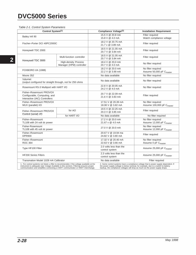
DVC5000 Series
May 19982-28
Table 2-1. Control System ParametersControl System (1) Compliance Voltage (2) Installation Requirement
Bailey Infi 9015.5 V @ 20.8 mA15.8 V @ 4.0 mA
Filter requiredWatch compliance voltage
Fischer–Porter DCI 40PC2000C18.2 V @ 20.75 mA21.7 v @ 3.89 mA
Filter required
Honeywell TDC 200018.5 V @ 21.05 mA20.7 V @ 3.84 mA
Filter required
Honeywell TDC 3000
Multi-function controller 18.5 V @ 21.05 mA20.7 V @ 3.84 mA
Filter required
Honeywell TDC 3000High-density Process
Manager (HPM) controller18.4 V @ 20.0 mA20.7 V @ 4.0 mA
No filter required
FOXBORO I/A (1988)18.2 V @ 20.0 mA22.2 V @ 3.99 mA
No filter requiredAssume 50,000 pF Cmaster
Moore 352 No data available No filter required
Valumet(output configured for straight through, not for 250 ohms
No data available No filter required
Rosemount RS-3 Multiport with HART I/O 22.8 V @ 20.05 mA24.2 V @ 4.0 mA
No filter required
Fisher–Rosemount PROVOXConfigurable, Computing, andInteractive (IAC) Controllers
20.7 V @ 22.09 mA21.6 V @ 3.83 mA
Filter required
Fisher–Rosemount PROVOXMUX (parallel) I/O
17.51 V @ 20.39 mA18.08 V @ 3.82 mA
No filter requiredAssume 100,000 pF Cmaster
Fisher–Rosemount PROVOXControl (serial) I/O
for AO19.5 V @ 22.25 mA20.3 V @ 3.85 mA
Filter required
Control (serial) I/Ofor HART I/O No data available No filter required
Fisher–RosemountTL108 with 24 volt dc power
17.2 V @ 20.0 mA21.67 v @ 4.0 mA
No filter requiredAssume 12,000 pF Cmaster
Fisher-RosemountTL108 with 45 volt dc power
27.0 V @ 20.0 mA No filter requiredAssume 12,000 pF Cmaster
Fisher–RosemountDPR900
20.67 V @ 19.94 ma24.82 V @ 3.80 mA
Filter required
Fisher–RosemountROC 364
17.32 V @ 20.40 mA22.63 V @ 3.66 mA
No filter requiredAssume 0 pF Cmaster
Type HF100 Filter2.0 volts less than thecontrol system
Assume 25,000 pF Cmaster
HF200 Series Filters2.3 volts less than thecontrol system
Assume 25,000 pF Cmaster
Transmation Model 1028 mA Calibrator No data available Filter required1. For control systems not listed, a filter is recommended, if the voltage available at theinstrument is adequate (see Votage Available in this section). Filtering ensures propercommunication and simplifies connecting a HART communicator or HART interchange.
2. Some control systems have a compliance voltage that is power supply dependent. Ifthe power supply voltage is below nominal, for example, due to a switch to batterybackup, the compliance voltages will drop as much as the power supply drops.
2

Installation
May 1998 2-29
Table 2-2. Cable Characteristics
Cable Type Capacitance (1)
pF/FtCapacitance (1)
pF/MResistance (2)
Ohms/FtResistance (2)
Ohms/M
BS5308/1, 0.5 sq mm 61.0 200 0.022 0.074
BS5308/1, 1.0 sq mm 61.0 200 0.012 0.037
BS5308/1, 1.5 sq mm 61.0 200 0.008 0.025
BS5308/2, 0.5 sq mm 121.9 400 0.022 0.074
BS5308/2, 0.75 sq mm 121.9 400 0.016 0.053
BS5308/2, 1.5 sq mm 121.9 400 0.008 0.025
BELDEN 8303, 22 awg 63.0 206.7 0.030 0.098
BELDEN 8441, 22 awg 83.2 273 0.030 0.098
BELDEN 8767, 22 awg 76.8 252 0.030 0.098
BELDEN 8777, 22 awg 54.9 180 0.030 0.098
BELDEN 9501, 24 awg 50.0 164 0.048 0.157
BELDEN 9680, 24 awg 27.5 90.2 0.048 0.157
BELDEN 9729, 24 awg 22.1 72.5 0.048 0.157
BELDEN 9773, 18 awg 54.9 180 0.012 0.042
BELDEN 9829, 24 awg 27.1 88.9 0.048 0.157
BELDEN 9873, 20 awg 54.9 180 0.020 0.0691. The capacitance values represent capacitance from one conductor to all otherconductors and shield. This is the appropriate value to use in the cable length
calculations.2. The resistance values include both wires of the twisted pair.
2
DVC5000 Series
May 19982-30
2

275 HART Communicator Basics
May 1998 3-1
3-3
Section 3 Model 275 HART CommunicatorBasics
Display 3-2. . . . . . . . . . . . . . . . . . . . . . . . . . . . . . . . . . . . . . . . . . . . . . . . . . . . . . . . . . . . . . . . . . .
Action Keys 3-2. . . . . . . . . . . . . . . . . . . . . . . . . . . . . . . . . . . . . . . . . . . . . . . . . . . . . . . . . . . . . .
On-Off Key 3-2. . . . . . . . . . . . . . . . . . . . . . . . . . . . . . . . . . . . . . . . . . . . . . . . . . . . . . . . . . . . . .
Up Arrow Key 3-2. . . . . . . . . . . . . . . . . . . . . . . . . . . . . . . . . . . . . . . . . . . . . . . . . . . . . . . . . . . .
Down Arrow Key 3-2. . . . . . . . . . . . . . . . . . . . . . . . . . . . . . . . . . . . . . . . . . . . . . . . . . . . . . . . .
Left Arrow and Previous Menu Key 3-2. . . . . . . . . . . . . . . . . . . . . . . . . . . . . . . . . . . . . . .
Right Arrow and Select Key 3-2. . . . . . . . . . . . . . . . . . . . . . . . . . . . . . . . . . . . . . . . . . . . . .
Hot Key 3-3. . . . . . . . . . . . . . . . . . . . . . . . . . . . . . . . . . . . . . . . . . . . . . . . . . . . . . . . . . . . . . . . .
Software-Defined Function Keys 3-3. . . . . . . . . . . . . . . . . . . . . . . . . . . . . . . . . . . . . . .
Alphanumeric and Shift Keys 3-3. . . . . . . . . . . . . . . . . . . . . . . . . . . . . . . . . . . . . . . . . .
Menu Structure 3-4. . . . . . . . . . . . . . . . . . . . . . . . . . . . . . . . . . . . . . . . . . . . . . . . . . . . . . . . . .
Offline Menu 3-4. . . . . . . . . . . . . . . . . . . . . . . . . . . . . . . . . . . . . . . . . . . . . . . . . . . . . . . . . . . . . Polling 3-4. . . . . . . . . . . . . . . . . . . . . . . . . . . . . . . . . . . . . . . . . . . . . . . . . . . . . . . . . . . . . . . . . . System Information 3-4. . . . . . . . . . . . . . . . . . . . . . . . . . . . . . . . . . . . . . . . . . . . . . . . . . . . . . . Reviewing Instrument Device Descriptions 3-4. . . . . . . . . . . . . . . . . . . . . . . . . . . . . . . . . . . Simulation 3-5. . . . . . . . . . . . . . . . . . . . . . . . . . . . . . . . . . . . . . . . . . . . . . . . . . . . . . . . . . . . . . .
Online Menu 3-5. . . . . . . . . . . . . . . . . . . . . . . . . . . . . . . . . . . . . . . . . . . . . . . . . . . . . . . . . . . . .
Displaying the HART CommunicatorDevice Description Revision 3-5. . . . . . . . . . . . . . . . . . . . . . . . . . . . . . . . . . . . . . . . . .
3

DVC5000 Series
May 19983-2
INDICATES PRESENTDIRECTION OF THE SHIFT KEY
INDICATES MENU ITEMS CAN BE FOUND BY USING AND KEYS
INDICATES THAT USE OF THE LEFTARROW KEY WILLTAKE YOU BACK ONE MENU LEVEL
Figure 3-1. Model 275 HART Communicator
0
ABC7
DEF8
GHI 9
JKL4
MNO5
PQR6
STU1
0
VWX2
YZ/3
#%&
F1 F2 F3 F4
INDICATES USE OF RIGHT ARROW KEYWILL OPEN MENU BRANCH
SHIFT KEYS
ALPHANUMERIC KEYS
ACTION KEYS
FUNCTION KEYS
BLINKING HEARTINDICATESCOMMUNICATION WITH A FIELDVUEINSTRUMENT
INDICATES LOWBATTERY
:
A7021 / IL
DVC: TagFisher Dig Vlv Ctrl
2 Analog In 12.42mA 3 Pressure 4 Travel 53.69% 5 Drive Sgl 58.15%
SAVE
1 Main Menu (Setup)
NoteThe Model 275 HART Communicatordevice description revision (DD) deter-mines how the HART Communicatorinterfaces with the instrument. For in-formation on displaying the device de-scription revision, see page 3-5.
This section discusses the display, keypad, and menustructure for the HART Communicator, shown in figure3-1. This section also includes information fordisplaying the HART Communicator device descriptionrevision number. For information on connecting theHART Communicator to the instrument, see the“Installation” section, Section 2. For more informationon the HART Communicator, such as specificationsand servicing, see the Product Manual for the HARTCommunicator– MAN4275A00, included with theHART Communicator. This manual also is availablefrom Rosemount Inc., Measurement Division.
Display The HART Communicator communicates informationto you through an eight-line by twenty-one character
liquid crystal display (LCD). When connected to aninstrument, the top two lines of the display indicate theinstrument tag and type. The bottom line of the displayis reserved for dynamic labels. These dynamic labelsidentify the software-defined functions assigned to thefour function keys (F1 through F4) below the display.
Action Keys
On-Off Key Use this key to turn the HART Communicator on andoff. When the HART Communicator is turned on, itgoes through a self test routine and then automaticallysearches for a HART-compatible device. If no deviceis found, it displays the message “No Device Found.”then displays the main menu. Four choices areavailable from this screen: Offline, Online, FrequencyDevice, and Utility.
If a HART-compatible device is found, the HARTCommunicator displays the Online menu. For moreinformation on the Online and Offline menus, seeMenu Structure in this section, page 3-4.
When performing certain operations, the message“OFF KEY DISABLED” is displayed indicating theHART Communicator cannot be turned off. Thisfeature helps to avoid situations where the HARTCommunicator could be unintentionally turned off whilea device’s output is fixed or when configuration datahas not been sent to a device.
Up Arrow Key Use this key to move the cursor up through a menuand to scroll through lists of available characters andoptions when editing a field.
Down Arrow Key Use this key to move the cursor down through a menuand to scroll through lists of available characters andoptions when editing a field.
Left Arrow and Previous Menu Key Use this dual-function key to move the cursor to theleft or to return to the previous menu.
Right Arrow and Select Key Use this dual-function key to move the cursor to theright or to select the highlighted menu option.
3

275 HART Communicator Basics
May 1998 3-3
Hot Key Pressing this key turns on the HART Communicatorand, if connected to a FIELDVUE instrument, displaysthe Hot Key menu. This menu allows you to quickly:
� Change the instrument mode
� Change the control mode
� Change the instrument protection
� Stabilize/Optimize—permits increasing ordecreasing the tuning to improve response
For details on instrument mode, control mode,protection, tuning sets, and other configurationparameters, see the “Detailed Setup” section, Section5, of this manual.
Software-Defined Function KeysUse the four function keys, marked F1 through F4,located below the LCD to select the software functionsindicated by the dynamic labels. On any given menu,the label appearing above a function key indicates thefunction of that key for the current menu.
As you move between menus, different dynamic labelsappear over the four function keys. For example, inmenus providing access to on-line help, the HELPlabel may appear above the F1 key. In menusproviding access to the Home menu, the HOME labelmay appear above the F3 key. In many cases theSEND label appears indicating that you must press thecorresponding function key to send the informationyou have entered on the keypad to the FIELDVUEinstrument’s memory. Functions available include:
� HELP—gives you information regarding thedisplay selection.
� SEND—sends the information you have enteredto the instrument.
� BACK —takes you to the previously displayedmenu.
� HOME—takes you back to the Online menu.
� EXIT—takes you back to the menu from whichyou had requested the value of a variable that canonly be read.
� ABORT—cancels your entry and takes you backto the menu from which you had selected the currentvariable or routine. Values are not changed.
� OK—takes you to the next menu or instructionscreen.
� ENTER—sends the information you haveselected to the instrument or flags the value that is tobe sent to the instrument. If it is flagged to be sent, theSEND dynamic label appears as a function keyselection.
� DEL—deletes the character at the current cursorposition when entering a variable.
� ESC—cancels your entry and takes you back tothe menu from which you had selected the currentvariable. Values are not changed.
NoteFrom time to time the SAVE dynamic labelwill appear. Do not press the function keyassociated with SAVE. This key has noapplication to FIELDVUE instruments.
Alphanumeric and Shift KeysFigure 3-2 shows the alphanumeric and shift keys.The alphanumeric keys perform two functions: the fastselection of menu options and data entry.
From within any menu, you can select availableoptions in two ways. You can use the up and downarrow keys and the select key to access availableoptions, or just press the corresponding number on thealphanumeric keypad to select the desired option.
Some menus require data entry. When you press analphanumeric key alone from within an edit menu, thebold character in the center of the key appears. Theselarge characters include the numbers zero throughnine, the decimal point (.), and the dash symbol (–).To enter the other characters on the keys, first pressand release the appropriate shift key. Do not press thekeys simultaneously.
Example: to enter the letter “R”, press the followingkey sequence:
Pressing the right shift key activates shift and causesthe right shift arrow icon to appear in the upper right
3

DVC5000 Series
May 19983-4
Figure 3-2. Model 275 HART Communicator Alphanumeric andShift Keys
1STU
ABC
7DEF
8GHI
9JKL
4MNO
5PQR
6STU
1
0
VWX
2YZ/
3#%&
A7022 / IL
corner of the display. Pressing the ’6’ key causes an“R” to appear in the editable field.
Menu StructureThe HART Communicator is generally used in twoenvironments: offline (when not connected to aninstrument) and online (connected to an instrument).
Offline Menu Pressing the On/Off key when not connected to aFIELDVUE instrument causes the unit to perform aself test and inform you of the firmware and modulerevision numbers. After displaying the message “NoDevice Found.” the unit displays the main menu. Fourchoices are available from this screen: Offline, Online,Frequency Device, and Utility. The Offline menuallows you to configure the HART Communicator, viewHART Communicator system information, andsimulate an on-line connection. Offline configuration isnot available for the DVC5000 Series digital valvecontrollers.
Polling When several devices are connected in the sameloop, such as for split ranging, each device must beassigned a unique polling address. Use the Pollingoptions to configure the HART Communicator toautomatically search for all or specific connecteddevices.
To enter a polling option, select Utility from the Offlinemenu. Select Configure Communicator then selectPolling. Use the up and down arrow keys to highlight
one of the listed polling options, and press ENTER(F4) to select the highlighted option.
The Polling options are:
1. Never Poll —connects to a device at address 0,and if not found will not poll for devices at address1–15.
2. Ask Before Polling —connects to a device ataddress 0, and if not found asks if you want to poll fordevices at address 1–15.
3. Always Poll —connects to a device at address 0,and if not found will automatically poll for devices ataddress 1–15.
4. Digital Poll —automatically polls for devices ataddress 0–15 and lists devices found by tag.
To find individual device addresses, use the DigitalPoll option to find each connected device in the loopand list them by tag.
For more information on setting the polling address,see the “Detailed Setup” section, Section 5.
System Information To access the HART Communicator systeminformation, select System Information from the Utilitymenu.
The motherboard system information consists of theSerial Peripheral Interface Time (SPI Time) and theHART Communicator firmware revision number.
The module system information consists of hardwareand software data. For example, you can find thehardware revision, RAM size, and Flash size; or, thedifferent software revisions and binary sizes.
The Data Pack system information consists of theEEPROM size and revision number.
Reviewing Instrument DeviceDescriptionsThe HART Communicator memory module containsdevice descriptions for specific HART-compatibledevices. These descriptions make up the applicationsoftware that the communicator needs to recognizeparticular devices.
If you cannot find a specific HART-compatible deviceon your communicator, then the device revision youare looking for is not programmed into the memorymodule. In this instance you are limited to what isavailable within a generic device description.
To review the device descriptions programmed intoyour HART Communicator, select Simulation from theUtility menu. The Manufacturer Menu appears. TheManufacturer Menu contains a list of eachmanufacturer with device descriptions currentlyinstalled in your communicator’s memory module.
3

275 HART Communicator Basics
May 1998 3-5
Once you select a manufacturer, the Model Menuappears. The Model Menu lists the currently installeddevice models, or types, provided by the selectedmanufacturer.
Select one of the instrument models or types to seethe instrument device description and the Model 275HART Communicator device description revision thatsupports that instrument.
Simulation The HART Communicator provides a simulation modethat allows you to simulate an online connection to aHART-compatible device. The simulation mode is atraining tool that enables you to become familiar withthe various menus associated with a device withouthaving the HART Communicator connected to thedevice.
To simulate an online connection, select Utility fromthe Offline menu. Select Simulation then select FisherControls. Select DVC to see the menu structure forthe DVC5000 Series digital valve controller. Refer tothe appropriate sections of this manual for informationon the various menus.
Online Menu Pressing the On/Off key when connected to aFIELDVUE instrument causes the unit to perform aself test and inform you of the firmware and modulerevision numbers. The unit then displays the deviceOnline menu. The figure on the front cover foldout
shows an overview of the DVC5000 Series digitalvalve controller menu structure.
Displaying the HART CommunicatorDevice Description Revision Device Description (DD) Revision is the revisionnumber of the Fisher Controls Device Description thatresides in the HART Communicator. It defines how theHART Communicator is to interact with the user andinstrument.
HART Communicators with device description revision11 are used with firmware 3 and 4 instruments. Thereare two device descriptions used with firmwarerevision 5 instruments: 1 and 2. Device DescriptionRevision 1 is available in HART Communicators with1.25 megabyte memory modules. Device DescriptionRevision 2 is available in HART Communicators with 4and 8 megabyte memory modules.
You can display the device description from the Offlineor Online menu:
Offline Menu —To see the HART Communicatordevice description revision number from the Offlinemenu, select Utility, Simulation, Fisher Controls, andDVC.
Online Menu —To see the HART Communicatordevice description revision number from the Onlinemenu, connect the HART Communicator to aninstrument connected to a source supplying a 4 to 20mA signal. From the Online menu, select Main Menu,Display, 275 DD Rev.
3

DVC5000 Series
May 19983-6
3

Initial Setup and Calibration
May 1998 4-1
4-4
Section 4 Initial Setup and Calibration
Configuration Protection 4-2. . . . . . . . . . . . . . . . . . . . . . . . . . . . . . . . . . . . . . . . . . . . . . .
Instrument Mode 4-2. . . . . . . . . . . . . . . . . . . . . . . . . . . . . . . . . . . . . . . . . . . . . . . . . . . . . . . .
Initial Setup 4-2. . . . . . . . . . . . . . . . . . . . . . . . . . . . . . . . . . . . . . . . . . . . . . . . . . . . . . . . . . . . . .
Auto Setup 4-3. . . . . . . . . . . . . . . . . . . . . . . . . . . . . . . . . . . . . . . . . . . . . . . . . . . . . . . . . . . . . . Setup Wizard 4-3. . . . . . . . . . . . . . . . . . . . . . . . . . . . . . . . . . . . . . . . . . . . . . . . . . . . . . . . . . . .
Manual Setup 4-4. . . . . . . . . . . . . . . . . . . . . . . . . . . . . . . . . . . . . . . . . . . . . . . . . . . . . . . . . . . .
Auto Calibrate Travel 4-6. . . . . . . . . . . . . . . . . . . . . . . . . . . . . . . . . . . . . . . . . . . . . . . . . . .
Stabilizing or Optimizing Valve Response 4-7. . . . . . . . . . . . . . . . . . . . . . . . . . . .
4

DVC5000 Series
May 19984-2
Figure 4-1. Configuration Protection Jumper
+
–
Current Regulator DiodeMotorola 1N5314
A6472/IL
Configuration Protection To setup and calibrate the instrument, the protectionmust be set to None with the HART Communicator. Ifthe protection is not None, changing the protectionrequires placing a jumper across the Auxiliaryterminals in the terminal box.
� If the Auxiliary terminals are used as atransmitter input (see table 9-2), use the configurationjumper shown in figure 4-1.
� If the Auxiliary terminals are used for a switchinput (see table 9-2) use either the configurationjumper shown in figure 4-1 or a piece of wire withclips.
To remove protection:
1. Connect a 4 to 20 mA source to the instrument.
2. Connect the HART Communicator to theinstrument and turn it on.
3. Press the Hot key on the HART
Communicator and select Protection.
4. From the Protection menu, select None. Whenprompted by the HART Communicator, temporarilyattach the jumper to the AUX + and AUX – terminalsin the instrument terminal box.
Instrument Mode
To setup and calibrate the instrument, the instrumentmode must be Out Of Service.
To view the instrument mode, press the Hot Key andselect Instrument Mode. If the mode is not Out OfService, select Out Of Service from the InstrumentMode menu and press ENTER (F4).
Initial Setup
CAUTION
Changes to the instrument setup maycause changes in the output pressureor valve travel.
NoteTo setup and calibrate the instrument, theprotection must be None and theInstrument Mode must be Out Of Service.See Configuration Protection andInstrument Mode at the beginning of thissection for information on removinginstrument protection and changing theinstrument mode.
When the DVC5000 Series digital valve controller isordered as part of a control valve assembly, thefactory mounts the digital valve controller and sets upthe instrument as specified on the order. Whenmounting to a valve in the field, the instrument needsto be setup to match the instrument to the valve andactuator.
Before beginning initial setup, be sure the instrumentis correctly mounted as described in the “Installation”section, Section 2, and that the travel sensor isadjusted correctly. Refer to the Travel Sensor Adjustprocedures in the “Calibration” section, Section 6.
There are two initial setup procedures:
� Auto Setup —(Recommended for initial setup.)This procedure automatically selects the appropriateconfiguration parameters depending upon the actuatortype and size specified.
� Manual Setup —this procedure permits you toenter values for the following configurationparameters:
� Instrument Mode
� Control Mode
� Feedback Char
� Supply Pressure
� Zero Control Signal
� Invert Feedback
4

Initial Setup and Calibration
May 1998 4-3
� Travel Cutoff Low
� Tuning Set
� Auto Calib Travel
Auto Setup(1-1-1)
Setup Wizard (1–1–1–1) To have the HART Communicator automatically setupthe instrument using specified actuator information,from the Online Menu select Main Menu, Initial Setup,Auto Setup, and Setup Wizard. Follow the prompts onthe HART Communicator display to setup theinstrument.
1. Enter the manufacturer of the actuator on whichthe instrument is mounted. If the actuatormanufacturer is not listed, select Other.
2. Enter the actuator type. If the actuator type is notlisted, select Other.
3. Enter the actuator size.
4. Enter the instrument supply pressure.
5. Specify if factory defaults should be used for initialsetup. If you select YES for factory default, the HARTCommunicator sets the setup parameters to thevalues listed in table 4-1. If you select NO for thefactory defaults, the setup parameters listed in thetable remain at their previous settings.
Typically the setup wizard determines the requiredsetup information based upon the actuatormanufacturer and type specified. However, if youenter other for the actuator manufacturer or theactuator type, then you will be prompted for setupparameters such as:
Actuator type (single-acting or double-acting),Feedback characteristic (rotary shaft or
sliding-stem),Valve fail action (valve opens or closes when air is
lost, see Zero Control Signal under Manual Setup),
Table 4-1. DVC5000 Series Factory Default SettingsSetup Parameter Default Setting
Analog Input UnitsInput HighInput Low
mA20.0 mA
4.0 mA
Travel Range HighTravel Range Low
100%0%
Control ModeRestart Control ModeSelf-Test Shutdown
Analog (RSP)Resume LastAll Failures Disabled
Dynamic Bypass EnabledInput Filter TimeInput Characteristic
No0 secsLinear
Travel Limit HighTravel Limit LowTravel Cutoff HighTravel Cutoff Low
125%–25%
99.5%0.5%
Minimum Opening TimeMinimum Closing TimePolling Address
0 secs0 secs
0
WARNING
If you answer YES to the prompt forpermission to move the valve, the in-strument may move the valve throughits full travel range. To avoid personalinjury and property damage causedby the release of pressure or processfluid, provide some temporary meansof control for the process.
Travel sensor rotation. (increasing air pressurecauses the travel sensor shaft to rotate clockwise orcounterclockwise), The HART Communicator will askif it can move the valve to determine travel sensorrotation. If you answer yes, the instrument may strokethe valve the full travel span to determine travelsensor rotation. If you answer No, then you will haveto specify the rotation for increasing air pressure:clockwise or counterclockwise.
Instrument supply pressure range (see InstrumentSupply Pressure under Manual Setup), and
Tuning set (see Tuning Set under Manual Setup).
After the Setup Wizard completes the setup, press OKto return to the Auto Setup menu. Select Auto CalibTravel to automatically calibrate the instrument travel.Follow the prompts on the HART Communicatordisplay. The calibration procedure uses the valve andactuator stops as the 0% and 100% calibration points.For additional information, refer to Auto CalibrateTravel in this section.
If after completing auto setup and auto calibration thevalve seems slightly unstable or unresponsive, youcan improve operation by selecting Stabilize/Optimizefrom the Auto Setup menu. For additional information,refer to Stabilize/Optimize at the end of this section.
4

DVC5000 Series
May 19984-4
Manual Setup(1-1-2) If you want to enter the individual parameters for theinstrument initial setup, from the Online Menu selectMain Menu, Initial Setup, and Manual Setup. Thefollowing describe the parameters that appear duringmanual setup.
� Instrument Mode—Instrument Mode allows youto either take the instrument Out Of Service or place itIn Service. The instrument must be Out Of Service tochange configuration variables that affect controlprovided the calibration/configuration protection is setto None.
� Control Mode—Control Mode lets you definewhere the instrument reads its set point. Choose oneof the following control modes: Analog (RSP) orDigital.
Choose Analog (RSP) if the instrument is to receive itsset point over the 4–20 mA loop. Normally theinstrument control mode is Analog (RSP).
Choose Digital if the instrument is to receive its setpoint digitally, via the HART communications link.
A third mode, Test, is also displayed. Normally theinstrument should not be in the Test mode. The HART
Communicator automatically switches to this modewhenever it needs to stroke the valve, for example
during calibration or stroke output. However, if youabort from a procedure where the instrument is in theTest mode, it may remain in this mode. To take theinstrument out of the Test mode, select Control Modethen select either Analog (RSP) or Digital.
� Feedback Char—Select Rotary Shaft or SlidingStem. Refer to table 4-2 to determine the requiredfeedback characteristic.
� Inst Supply Pressure—Adjusts the range of theinstrument pressure sensor. Supply Pressure isconfigured in pressure units of psi, bar, or kPa. Selecta supply pressure range that includes the instrumentsupply pressure.
� Zero Ctrl Signal—Identifies whether the valve isfully open or fully closed when the input is 0%. If youare unsure how to set this parameter, disconnect thecurrent source to the instrument. The resulting valvetravel is the Zero Control Signal. (With direct actingdigital valve controllers, disconnecting the currentsource is the same as setting the output pressure tozero.)
Table 4-2. Feedback Characteristic Selections for VariousActuator Types
Actuator Type Feedback Characteristic
513 and 513R657 and 667
1250 and 1250RSystem 9000
Baumann or Gulde
Sliding Stem
471585 and 585R1051 and 1052
1066SRand all Type
DVC5030(1) applications
Rotary
1. Type DVC5030 digital valve controllers have the travel sensor shaft extendingfrom the back of the housing as shown in figure 10-3.
Table 4-3. DVC5010 and DVC5020 Invert Feedback SelectionsActuator Invert Feedback
Sliding-Stem Actuators
513 Yes
513R No
585C Yes
585CR No
657 Yes
667 No
1250 Yes
1250R No
Rotary Actuators
1051 Yes
1052 Yes
Baumann Actuators
Air to Extend Yes
Air to Retract No
Table 4-4. DVC5030 Invert Feedback SelectionsType 1051, 1052, and 1066SR Actuators
Mounting Style Invert Feedback
A Yes
B No
C No
D Yes
Table 4-5. DVC5040 Invert Feedback SelectionsActuator Invert Feedback
System 9000 fail-closed No
System 9000 fail-open Yes
� Invert Feedback—Select YES or NO, or AUTOSET. Invert feedback establishes the proper valvetravel feedback orientation. Determine the InvertFeedback selection by viewing the rotation of the endof the travel sensor shaft. If increasing air pressure tothe actuator causes the shaft to turn clockwise, enterYES. If it causes the shaft to turn counter-clockwise,enter NO. Tables 4-3 through 4-5 list the requiredInvert Feedback selections for Fisher Controlsactuators. To have the instrument determine the invertfeedback, select Auto Set.
4

Initial Setup and Calibration
May 1998 4-5
Table 4-6. Tuning Set Selection Guidelines(Fisher Actuators)
T ningActuator Type and Size
TuningSet 513 & 513R 585C & 585CR 657 & 667 1051 & 1052 1066SR 1250 & 1250R System
9000
E 20, 32 - - - - - - - - - - - - - - - - - -
F - - - 25 - - - - - - - - - - - - 12, 20
G - - - - - - - - - - - - 20 - - - 25, 50
H - - - - - - 30 20, 30, 33 - - - 225 - - -
I - - - - - - - - - - - - - - - - - - - - -
J - - - 50 - - - - - - - - - 450 - - -
K - - - - - - 34, 40 40 - - - - - - 80
L - - - - - - 45, 50 - - - 27, 75 675 - - -
M - - - - - - 46, 60, 70, 87,80, 100
60, 70 - - - - - - - - -
Table 4-7. Tuning Set Selection Guidelines (BaumannActuators)
TuningAct ator Size
TuningSet Actuator Size
E 32
H 54
K 70
Table 4-8. Tuning Set Selection Guidelines (Gulde Actuators)
TUNING ACTUATOR TYPE AND SIZETUNINGSET 3024 3025
E GA 1.21 - - -
H GA 1.31 - - -
K GA 1.41 - - -
M - - - P460, P462, P900
Table 4-9. Tuning Set Selection Guidelines (Other Actuators)ACTUATOR TYPE AND SIZE
TUNINGSET Neles-Jamesbury
Quadra-Power IIMasoneilanCamflex II
MasoneilanSigma F,
Minitorque, &Ball II
D - - - 4.5 A
H QP2, QP3 6 or 7 B
I - - - - - - - - -
J QP4 - - - - - -
K QP5 - - - C
� Tvl Cutoff Low—Travel Cutoff Low defines thelow cutoff point for the travel. Travel Cutoff Low canbe used to ensure proper seat load is applied to thevalve. When travel is below the travel cutoff low,instruments with firmware revision 5 set the output tozero or to full supply pressure, depending upon thezero control signal. Instruments with firmware revision3 or 4 set the travel target to –23.0% of the rangedtravel. A Travel Cutoff Low of 0.5% is recommendedto help ensure maximum shutoff seat loading.
Table 4-10. Gain and Rate Values for Preselected TuningSets(1)
TUNINGHIGH PERFORMANCE STANDARD
TUNINGSET GAIN Tvl Rate Press
RateGAIN Tvl Rate
CDEFG
0.81.41.82.22.8
10.010.010.010.010.5
7543332735
0.400.500.600.751.00
13.013.013.013.013.0
HIJKLM
3.44.05.06.08.0
10.0
11.612.714.516.218.018.0
516250423125
1.302.003.003.995.256.99
13.013.013.013.013.013.0
1. For user adjusted, the high performance gain and standard gain may beindependently adjusted over the range of 0.01 to 25.
When a Travel Cutoff Low is set, the Travel Limit Lowis deactivated, since only one of these parameters canbe active. Travel Cutoff Low is deactivated by setting itto –25.0%.
CAUTION
Changes to the tuning set can result invalve/actuator instability.
� Tuning Set—There are eleven tuning sets tochoose from. Each tuning set provides a preselectedvalue for the digital valve controller gain and ratesettings. Tuning set C provides the slowest responseand M provides the fastest response. Table 4-10 liststhe high performance and standard gain and ratevalues for preselected tuning sets used with firmware5. Normally the instrument uses the high performancevalues. However, should the pressure sensor fail, theunit will continue to operate using the standard values.Instruments with firmware revisions 3 and 4 alwaysuse the standard values.
In addition, you can select User Adjusted or Expert,which allows you to modify tuning of the digital valvecontroller. With User Adjusted you can specify the
4
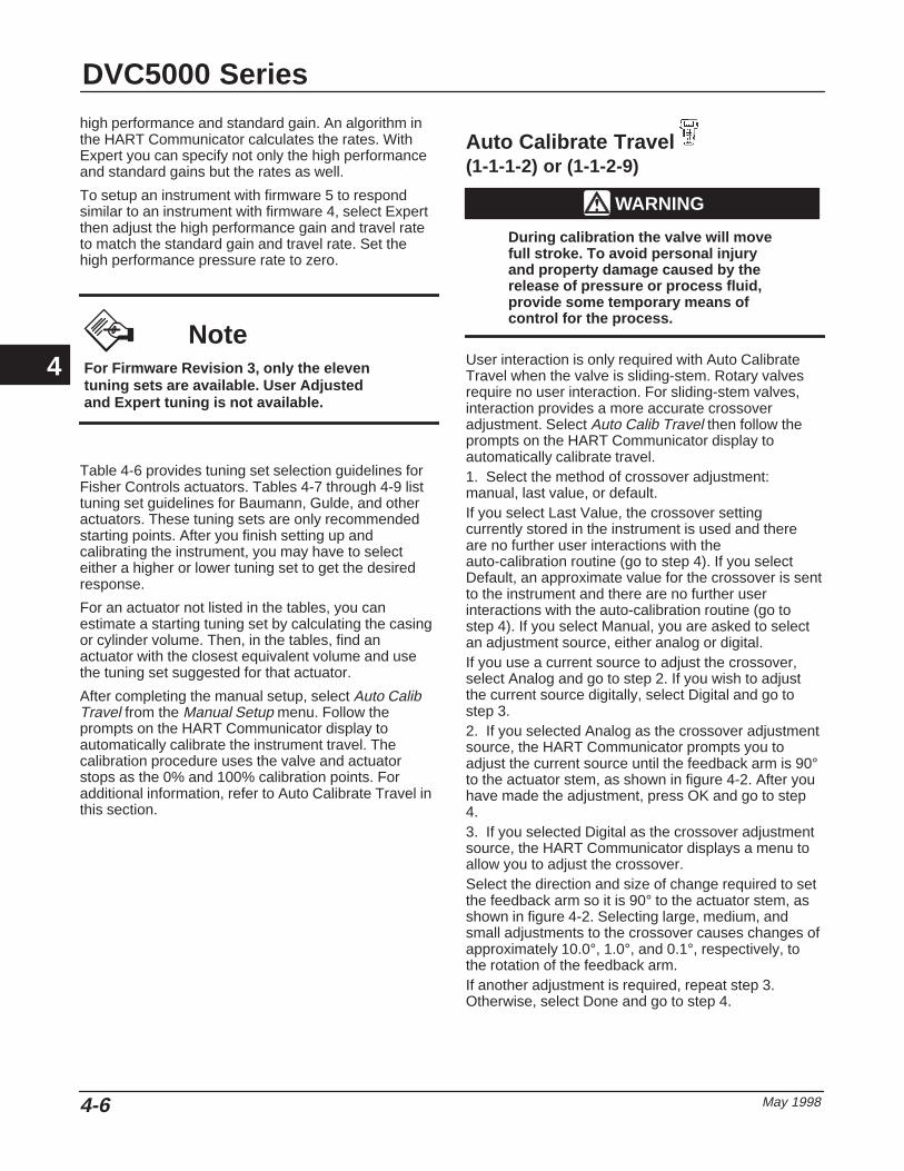
DVC5000 Series
May 19984-6
high performance and standard gain. An algorithm inthe HART Communicator calculates the rates. WithExpert you can specify not only the high performanceand standard gains but the rates as well.
To setup an instrument with firmware 5 to respondsimilar to an instrument with firmware 4, select Expertthen adjust the high performance gain and travel rateto match the standard gain and travel rate. Set thehigh performance pressure rate to zero.
NoteFor Firmware Revision 3, only the eleventuning sets are available. User Adjustedand Expert tuning is not available.
Table 4-6 provides tuning set selection guidelines forFisher Controls actuators. Tables 4-7 through 4-9 listtuning set guidelines for Baumann, Gulde, and otheractuators. These tuning sets are only recommendedstarting points. After you finish setting up andcalibrating the instrument, you may have to selecteither a higher or lower tuning set to get the desiredresponse.
For an actuator not listed in the tables, you canestimate a starting tuning set by calculating the casingor cylinder volume. Then, in the tables, find anactuator with the closest equivalent volume and usethe tuning set suggested for that actuator.
After completing the manual setup, select Auto CalibTravel from the Manual Setup menu. Follow theprompts on the HART Communicator display toautomatically calibrate the instrument travel. Thecalibration procedure uses the valve and actuatorstops as the 0% and 100% calibration points. Foradditional information, refer to Auto Calibrate Travel inthis section.
Auto Calibrate Travel(1-1-1-2) or (1-1-2-9)
WARNING
During calibration the valve will movefull stroke. To avoid personal injuryand property damage caused by therelease of pressure or process fluid,provide some temporary means ofcontrol for the process.
User interaction is only required with Auto CalibrateTravel when the valve is sliding-stem. Rotary valvesrequire no user interaction. For sliding-stem valves,interaction provides a more accurate crossoveradjustment. Select Auto Calib Travel then follow theprompts on the HART Communicator display toautomatically calibrate travel.1. Select the method of crossover adjustment:manual, last value, or default.If you select Last Value, the crossover settingcurrently stored in the instrument is used and thereare no further user interactions with theauto-calibration routine (go to step 4). If you selectDefault, an approximate value for the crossover is sentto the instrument and there are no further userinteractions with the auto-calibration routine (go tostep 4). If you select Manual, you are asked to selectan adjustment source, either analog or digital.If you use a current source to adjust the crossover,select Analog and go to step 2. If you wish to adjustthe current source digitally, select Digital and go tostep 3.2. If you selected Analog as the crossover adjustmentsource, the HART Communicator prompts you toadjust the current source until the feedback arm is 90°to the actuator stem, as shown in figure 4-2. After youhave made the adjustment, press OK and go to step4.3. If you selected Digital as the crossover adjustmentsource, the HART Communicator displays a menu toallow you to adjust the crossover.Select the direction and size of change required to setthe feedback arm so it is 90° to the actuator stem, asshown in figure 4-2. Selecting large, medium, andsmall adjustments to the crossover causes changes ofapproximately 10.0°, 1.0°, and 0.1°, respectively, tothe rotation of the feedback arm.If another adjustment is required, repeat step 3.Otherwise, select Done and go to step 4.
4
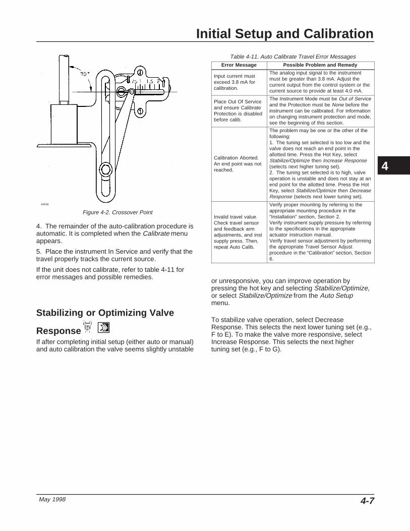
Initial Setup and Calibration
May 1998 4-7
A6536
Figure 4-2. Crossover Point
4. The remainder of the auto-calibration procedure isautomatic. It is completed when the Calibrate menuappears.
5. Place the instrument In Service and verify that thetravel properly tracks the current source.
If the unit does not calibrate, refer to table 4-11 forerror messages and possible remedies.
Stabilizing or Optimizing Valve
Response
If after completing initial setup (either auto or manual)and auto calibration the valve seems slightly unstable
Table 4-11. Auto Calibrate Travel Error MessagesError Message Possible Problem and Remedy
Input current mustexceed 3.8 mA forcalibration.
The analog input signal to the instrumentmust be greater than 3.8 mA. Adjust thecurrent output from the control system or thecurrent source to provide at least 4.0 mA.
Place Out Of Serviceand ensure CalibrateProtection is disabledbefore calib.
The Instrument Mode must be Out of Serviceand the Protection must be None before theinstrument can be calibrated. For informationon changing instrument protection and mode,see the beginning of this section.
Calibration Aborted.An end point was notreached.
The problem may be one or the other of thefollowing:1. The tuning set selected is too low and thevalve does not reach an end point in theallotted time. Press the Hot Key, selectStabilize/Optimize then Increase Response(selects next higher tuning set).2. The tuning set selected is to high, valveoperation is unstable and does not stay at anend point for the allotted time. Press the HotKey, select Stabilize/Optimize then DecreaseResponse (selects next lower tuning set).
Invalid travel value.Check travel sensorand feedback armadjustments, and instsupply press. Then,repeat Auto Calib.
Verify proper mounting by referring to theappropriate mounting procedure in the“Installation” section, Section 2.Verify instrument supply pressure by referringto the specifications in the appropriateactuator instruction manual.Verify travel sensor adjustment by performingthe appropriate Travel Sensor Adjustprocedure in the “Calibration” section, Section6.
or unresponsive, you can improve operation bypressing the hot key and selecting Stabilize/Optimize,or select Stabilize/Optimize from the Auto Setupmenu.
To stabilize valve operation, select DecreaseResponse. This selects the next lower tuning set (e.g.,F to E). To make the valve more responsive, selectIncrease Response. This selects the next highertuning set (e.g., F to G).
4

DVC5000 Series
May 19984-8
4

Detailed Setup
May 1998 5-1
5-5
Section 5 Detailed Setup
Menu and Quick Key Sequence Tables Front Cover. . . . . . . . . . . . . . . . . . . . . . . . . . . . . . . .
Modes 5-3. . . . . . . . . . . . . . . . . . . . . . . . . . . . . . . . . . . . . . . . . . . . . . . . . . . . . . . . . . . . . . . . . . . .
Instrument Mode 5-3. . . . . . . . . . . . . . . . . . . . . . . . . . . . . . . . . . . . . . . . . . . . . . . . . . . . . . . . .
Control Mode 5-4. . . . . . . . . . . . . . . . . . . . . . . . . . . . . . . . . . . . . . . . . . . . . . . . . . . . . . . . . . . .
Restart Control Mode 5-4. . . . . . . . . . . . . . . . . . . . . . . . . . . . . . . . . . . . . . . . . . . . . . . . . . . .
Burst Mode 5-4. . . . . . . . . . . . . . . . . . . . . . . . . . . . . . . . . . . . . . . . . . . . . . . . . . . . . . . . . . . . . .
Restarting the Instrument 5-4. . . . . . . . . . . . . . . . . . . . . . . . . . . . . . . . . . . . . . . . . . . . . .
Protection 5-4. . . . . . . . . . . . . . . . . . . . . . . . . . . . . . . . . . . . . . . . . . . . . . . . . . . . . . . . . . . . . . . .
General Information 5-6. . . . . . . . . . . . . . . . . . . . . . . . . . . . . . . . . . . . . . . . . . . . . . . . . . . . .
HART Tag
Message
Descriptor
Date
Valve Serial Number
Factory Instrument Serial Number
Field Instrument Serial Number
Polling Address
Actuator Information 5-7. . . . . . . . . . . . . . . . . . . . . . . . . . . . . . . . . . . . . . . . . . . . . . . . . . . .
Instrument Supply Pressure
Feedback Characteristic
Zero Control Signal
Invert Feedback
Measured Variable Units and Ranges 5-7. . . . . . . . . . . . . . . . . . . . . . . . . . . . . . . . .
Analog Input Units and Range
Pressure Units
Temperature Units
Response 5-8. . . . . . . . . . . . . . . . . . . . . . . . . . . . . . . . . . . . . . . . . . . . . . . . . . . . . . . . . . . . . . . .
Tuning Set
5

DVC5000 Series
May 19985-2
Input Characteristic
Input Filter Time
Dynamic Bypass Enable
Minimum Opening and Closing Time
Travel Ranges, Limits, and Cutoffs 5-10. . . . . . . . . . . . . . . . . . . . . . . . . . . . . . . . . . . .
Travel Ranges 5-10. . . . . . . . . . . . . . . . . . . . . . . . . . . . . . . . . . . . . . . . . . . . . . . . . . . . . Travel Range HighTravel Range Low
Travel Limits and Cutoffs 5-11. . . . . . . . . . . . . . . . . . . . . . . . . . . . . . . . . . . . . . . . . . . . Travel Limit HighTravel Limit LowTravel Cutoff HighTravel Cutoff Low
Alerts 5-11. . . . . . . . . . . . . . . . . . . . . . . . . . . . . . . . . . . . . . . . . . . . . . . . . . . . . . . . . . . . . . . . . . . . .
Travel Alerts 5-12. . . . . . . . . . . . . . . . . . . . . . . . . . . . . . . . . . . . . . . . . . . . . . . . . . . . . . . Alerts 1 and 2 5-12. . . . . . . . . . . . . . . . . . . . . . . . . . . . . . . . . . . . . . . . . . . . . . . . . . . . . . . . . . . . Deviation Alert 5-12. . . . . . . . . . . . . . . . . . . . . . . . . . . . . . . . . . . . . . . . . . . . . . . . . . . . . . . . . . . Accumulation Alert 5-13. . . . . . . . . . . . . . . . . . . . . . . . . . . . . . . . . . . . . . . . . . . . . . . . . . . . . . .
Cycle Counter Alert 5-13. . . . . . . . . . . . . . . . . . . . . . . . . . . . . . . . . . . . . . . . . . . . . . . . .
Drive Signal Alert Enable 5-14. . . . . . . . . . . . . . . . . . . . . . . . . . . . . . . . . . . . . . . . . . . . . . . . .
Misc Alerts 5-14. . . . . . . . . . . . . . . . . . . . . . . . . . . . . . . . . . . . . . . . . . . . . . . . . . . . . . . . Auxiliary Input Alert EnableAuxiliary Input Alert State
Alert Record 5-14. . . . . . . . . . . . . . . . . . . . . . . . . . . . . . . . . . . . . . . . . . . . . . . . . . . . . . . . . . . . . Display RecordCopy RecordInstrument Date and TimeRecord Groups
Self-Test Failures for Shutdown 5-15. . . . . . . . . . . . . . . . . . . . . . . . . . . . . . . . . . . . . . .
No Free Time Fail
RAM Fail
Critical NVM Fail
Temperature Sensor Fail
Travel Sensor Fail
Drive Current Fail
5

Detailed Setup
May 1998 5-3
NoteDetailed setup is not available for in-strument level AC.
The Detailed Setup selection from the Main Menuallows you to configure the digital valve controller toyour application. Table 5-1 lists the default settings fora standard factory configuration. You can adjustactuator response, set the various modes, alerts,ranges, travel cutoffs and limits. You can also restartthe instrument and set the protection.
Setting Modes To view or change the mode, select Main Menu,Detailed Setup, Mode. Follow the prompts on theHART Communicator display to view or changeinformation in the following fields: Instrument Mode,Control Mode, Restart Ctrl Mode (Restart ControlMode), Restart, and Burst Mode.
Instrument Mode
You can change the instrument mode by selectingInstrument Mode from the Mode menu, or press theHot Key and select Instrument Mode.
Instrument Mode allows you to either take theinstrument Out Of Service or place it In Service.Taking the instrument Out Of Service allows you toperform instrument calibration and also allows you tochange configuration variables that affect control,provided the calibration/configuration protection isproperly set. See Setting Protection.
NoteSome changes that require the instrumentto be taken Out Of Service will not takeeffect until the instrument is placed backIn Service or the instrument is restarted.
Table 5-1. Factory Default Detailed Setup ParametersSetup Parameter Default Setting (1)
Control ModeRestart Control ModeBurst Mode EnabledBurst Mode CommandHART Tag
Analog (RSP)Resume Last
No3
As specified on order
MessageDescriptorDateValve Serial NumberPolling Address
BlankBlank
Factory Calibration DateBlank
0
Inst Supply PressureFeedback CharacteristicZero Control SignalInvert Feedback
20(2)
Rotary Shaft(2)
Open(2)
Yes(2)
Analog Input UnitsInput Range HighInput Range LowTravel Range HighTravel Range Low
mA20 mA4.0 mA100%
0%
Pressure UnitsTemperature UnitsTuning SetInput CharacteristicInput Filter Time
PSIF
C(2)
LinearFilter Off
Dynamic Bypass EnabledTravel Limit HighTravel Limit LowTravel Cutoff HighTravel Cutoff Low
No125%–25%99.5%0.5%
Minimum Opening TimeMinimum Closing TimeTravel Alert 1 EnabledTravel Alert 2 Enabled
0 secs0 secs
NoNo
Travel Alert 1 High PointTravel Alert 1 Low PointTravel Alert 2 High PointTravel Alert 2 Low PointTravel Alert Deadband
125%–25%125%–25%
3%
Travel Deviation Alert EnableTravel Deviation Alert PointTravel Deviation Time
No125%4 secs
Cycle Counter Alert EnableCycle Counter Alert PointCycle Counter DeadbandCycle Counter
No4,294,967,295
3%0
Travel Accumulator Alert EnableTravel Accumulator Alert PointTravel Accumulator DeadbandTravel Accumulator
No4,294,967,295%
3%0
Auxiliary Input Alert EnableAuxiliary Input Alert StateDrive Alert EnableNo Free Time FailRAM Fail
NoClosed
NoNoNo
Drive Current FailCritical NVM FailTemperature Sensor FailTravel Sensor Fail
NoNoNoNo
1. The settings listed are for standard factory configuration. DVC5000 Seriesinstruments can also be ordered with custom configuration settings. For the defaultcustom settings, refer to the order requistion.2. If the instrument is shipped mounted on an actuator, these values depend uponthe actuator on which the instrument is mounted.
5
DVC5000 Series
May 19985-4
Control Mode
You can change the control mode by selecting ControlMode from the Mode menu, or press the Hot Key andselect Control Mode.
Control Mode lets you define where the instrumentreads its set point. Follow the prompts on the HARTCommunicator display to choose one of the followingcontrol modes: Analog (RSP) or Digital.
Choose Analog (RSP) if the instrument is to receive itsset point over the 4–20 mA loop. Normally theinstrument control mode is Analog (RSP).
Choose Digital if the instrument is to receive its setpoint digitally, via the HART communications link.
A third mode, Test is also displayed. Normally theinstrument should not be in the Test mode. The HARTCommunicator automatically switches to this modewhenever it needs to stroke the valve, for exampleduring calibration or stroke output. However, if youabort from a procedure where the instrument is in theTest mode, it may remain in this mode. To take theinstrument out of the Test mode, select Control Modethen select either Analog (RSP) or Digital.
Restart Control Mode
(1-2-1-3)Restart Control Mode (Restart Ctrl Mode) lets youchoose which operating mode you want the instrumentto be in after a restart. Follow the prompts on theHART Communicator display to define the restartcontrol mode as Resume Last, Analog (RSP), orDigital.
Burst Mode
(1-2-1-5)Enabling burst mode provides continuous communica-tion from the digital valve controller. All DVC5000Series digital valve controllers with firmware revision 5are capable of burst mode communication. Burstmode applies only to the transmission of burst modedata (travel, travel set point, actuator pressure, andauxiliary input status) and does not affect the wayother data is accessed.
Access to information in the instrument is normallyobtained through the poll/response of HARTcommunication. The Model 275 HART Communicatoror the control system may request any of theinformation that is normally available, even while the
instrument is in burst mode. Between each burst modetransmission sent by the instrument, a short pauseallows the HART Communicator or control system toinitiate a request. The instrument receives the request,processes the response message, and then continues“bursting” the burst mode data.
There are four burst mode commands. Command 3 isrecommended for use with the Rosemount� Model333 HART Tri-Loop� HART-to-analog signalconverter. The other three are not used at this time.
Command 3 provides the following variables:
� Primary variable—travel in % of ranged travel,
� Secondary variable—travel setpoint in % ofranged travel,
� Tertiary variable—actuator pressure in psig, bar,or kPa
� Fourth variable—auxiliary input status in %; 0%equals open, 100% equals closed.
To enable burst mode, select Main Menu, DetailedSetup, Mode, Burst, and Burst Enable. To send aburst mode command, select Main Menu, DetailedSetup, Mode, Burst, and Burst Command. Burst modemust be enabled before you can change the burstmode command.
Restarting the Instrument
(1-2-1-4) Restart resets the instrument in the same manner aswhen power to the instrument is interrupted. WhenRestart is issued, all of the newly entered configurationvariables become active. Otherwise, they may nottake effect until the instrument is placed In Service.
Setting Protection Some setup parameters may require changing theprotection with the HART Communicator. In somecases, a jumper must be placed across the Auxiliaryterminals in the terminal box in order to changeprotection.
� If the Auxiliary terminals are used as atransmitter input (see table 9-2), use the configurationjumper shown in figure 5-1.
� If the Auxiliary terminals are used for a switchinput (see table 9-2) use either the configuration
5

Detailed Setup
May 1998 5-5
Table 5-2. Conditions for Modifying DVC5000 Series Digital Valve Controller Parameters
Parameters In Service/Config Protected
In Service/Config Unprotected
Out of Service/Config Protected
Out of Service/Config Unprotected
Control ModeRestart Ctrl ModeBurst Mode EnableBurst Mode CommandProtection
- - -- - -�
- - -�
- - -- - -�
- - -�
�
- - -�
- - -�
�
�
�
�
�
TagMessageDescriptorDateValve Serial NumField Inst S/NPolling Address
- - -- - -- - -- - -- - -- - -- - -
�
�
�
�
�
- - -- - -
- - -- - -- - -- - -- - -- - -- - -
�
�
�
�
�
�
�
Inst Supply PressureFeedback CharZero Ctrl SignalInvert Feedback
- - -- - -- - -- - -
- - -- - -- - -- - -
- - -- - -- - -- - -
�
�
�
�
Analog In Units/RngInput Range HighInput Range LowTvl Range HighTvl Range LowPressure UnitsTemp Units
- - -- - -- - -- - -- - -- - -�
- - -- - -- - -- - -- - -- - -�
- - -- - -- - -- - -- - -- - -�
�
�
�
�
�
�
�
Tuning SetGainInput CharDefine Custom CharInput Filter TimeDyn Bypass Enab
- - -- - -- - -- - -- - -- - -
- - -- - -- - -- - -- - -- - -
- - -- - -- - -- - -- - -- - -
�
�
�
�
�
�
Tvl Limit HighTvl Limit LowTvl Cutoff HighTvl Cutoff Low
- - -- - -- - -- - -
- - -- - -- - -- - -
- - -- - -- - -- - -
�
�
�
�
Min Opening TimeMin Closing Time
- - -- - -
- - -- - -
- - -- - -
�
�
Tvl Alrt 1 EnabTvl Alrt 2 EnabTvl Alrt 1 High PtTvl Alrt 1 Low PtTvl Alrt 2 High PtTvl Alrt 2 Low PtTvl Alrt DB
�
�
�
�
�
�
�
�
�
�
�
�
�
�
�
�
�
�
�
�
�
�
�
�
�
�
�
�
Tvl Dev Alrt EnabTvl Dev Alrt PtTvl Dev Time
�
�
�
�
�
�
�
�
�
�
�
�
Cycl Cnt Alrt EnabCycl Count Alrt PtCycl Count DBCycl Count
�
�
�
�
�
�
�
�
�
�
�
�
�
�
�
�
Tvl Acum Alrt EnabTvl Acum Alrt PtTvl Acum DBTvl Acum
�
�
�
�
�
�
�
�
�
�
�
�
�
�
�
�
Aux In Alrt EnabAux In Alrt StateDrive Alrt Enab
�
�
�
�
�
�
�
�
�
�
�
�
�—indicates parameter may be modified for instrument mode and protection shown.
–Continued–
5

DVC5000 Series
May 19985-6
Table 5-2. Conditions for Modifying DVC5000 Series Digital Valve Controller Parameters (Continued)
Parameters In Service/Config Protected
In Service/Config Unprotected
Out of Service/Config Protected
Out of Service/Config Unprotected
No Free Time FailRAM FailDrive Current FailCritical NVM FailTemp Sensor FailTvl Sensor Fail
- - -- - -- - -- - -- - -- - -
- - -- - -- - -- - -- - -- - -
- - -- - -- - -- - -- - -- - -
�
�
�
�
�
�
�—indicates parameter may be modified for instrument mode and protection shown.
Figure 5-1. Configuration Protection Jumper
+
–
Current Regulator DiodeMotorola 1N5314
A6472/IL
jumper shown in figure 5-1 or a piece of wire withclips.
Two levels of protection are available:
� Config & Calib—Both setup and calibration areprotected. Prohibits changing calibration and protectedsetup parameters.
� None—Neither setup nor calibration is protected.Allows changing calibration and setup parameters.
Table 5-2 lists configurable parameters in theinstrument and the requirements for modifying theseparameters, in terms of instrument mode andprotection.
To change an instrument’s protection, press the Hotkey on the HART Communicator and select
Protection. Select the desired level of protection.Follow the prompts on the HART Communicatordisplay to set the protection level. If necessary,temporarily attach the jumper to the AUX + and AUX –terminals in the instrument terminal box whenprompted by the HART Communicator.
General Information
(1-2-3)Select Main Menu, Detailed Setup, and General.Follow the prompts on the HART Communicatordisplay to enter or view information in the followingfields: HART Tag, Message, Descriptor, Date, ValveSerial Num (Valve Serial Number), Factory Inst S/N
(Factory Instrument Serial Number), Field Inst S/N(Field Instrument Serial Number), and Polling Address.
� HART Tag—Enter an up to 8 character HARTtag for the instrument.
� Message—Enter any message with up to 32characters.
� Descriptor—Enter a descriptor for the applicationwith up to 16 characters.
� Date—Enter a date with the format MM/DD/YY.
� Valve Serial Num—Enter the serial number forthe valve in the application with up to 12 characters.
� Factory Inst S/N—The Factory Instrument SerialNumber is displayed. You cannot change this.
� Field Inst S/N—The Field Instrument SerialNumber is assigned to the printed wiring board by thefactory and can be changed in the field.
A FIELDVUE instrument has three instrument serialnumbers: One stamped on the instrument nameplateand two assigned to the printed wiring board. Whenthe instrument ships from the factory, all three serialnumbers are the same. The Factory Instrument SerialNumber is assigned to the printed wiring board by thefactory and cannot be changed. The Field InstrumentSerial Number is also assigned to the printed wiringboard by the factory but CAN be changed.
If you replace the printed wiring board in an instrumentor move it to a different instrument, change the FieldInstrument Serial Number to match the serial numberon the instrument nameplate where you are installingthe printed wiring board. Factory Instrument and FieldInstrument Serial Numbers that do not match identify aprinted wiring board that is not the original board thatshipped with the instrument from the factory.
� Polling Address—If the digital valve controller isused in a point-to-point configuration, the PollingAddress is 0. When several devices are connected inthe same loop, such as for split ranging, each devicemust be assigned a unique polling address. ThePolling Address is set to a value between 0 and 15. Tochange the polling address the instrument must beOut Of Service.
5

Detailed Setup
May 1998 5-7
For the HART Communicator to be able tocommunicate with a device whose polling address isnot 0, it must be configured to automatically search forall or specific connected devices. For information onconfiguring the HART Communicator for automaticpolling, see the “Model 275 HART CommunicatorBasics” section, Section 3.
Actuator Information
(1-2-4)Select Main Menu, Detailed Setup, and Actuator Info.Follow the prompts on the HART Communicatordisplay to enter or view information in the followingfields: Inst Supply Press (Instrument SupplyPressure), Feedback Char (Feedback Characteristic),Zero Ctrl Signal (Zero Control Signal), and InvertFeedback.
� Inst Supply Press—Adjusts the range of theinstrument pressure sensor. Supply Pressure isconfigured in pressure units of psi, bar, or kPa. Selecta supply pressure range that includes the instrumentsupply pressure.
� Feedback Char—Select Rotary Shaft or SlidingStem. Refer to table 5-3 to determine the requiredfeedback characteristic.
� Zero Ctrl Signal—Identifies whether the valve isfully open or fully closed when the input is 0%. If youare unsure how to set this parameter, disconnect thecurrent source to the instrument. The resulting valvetravel is the Zero Control Signal. (With direct actingdigital valve controllers, disconnecting the currentsource is the same as setting the output pressure tozero.)
� Invert Feedback—Select YES, NO, or AUTOSET. Invert feedback establishes the proper valvetravel feedback orientation. Determine the InvertFeedback selection by viewing the rotation of the endof the travel sensor shaft. If increasing air pressure tothe actuator causes the shaft to turn clockwise, enterYES. If it causes the shaft to turn counter-clockwise,enter NO. Tables 5-4 through 5-6 show the requiredInvert Feedback selections for Fisher Controlsactuators. To have the instrument determine the invertfeedback, select Auto Set.
Table 5-3. Feedback Characteristic Selections for VariousActuator Types
Actuator Type Feedback Characteristic
513 and 513R657 and 667
1250 and 1250RSystem 9000
Baumann or Gulde
Sliding Stem
471585 and 585R1051 and 1052
1066SRand all Type
DVC5030(1) applications
Rotary
1. Type DVC5030 digital valve controllers have the travel sensor shaft extendingfrom the back of the housing as shown in figure 10-3.
Table 5-4. DVC5010 and DVC5020 Invert Feedback SelectionsActuator Invert Feedback
Sliding-Stem Actuators
513 Yes
513R No
585C Yes
585CR No
657 Yes
667 No
1250 Yes
1250R No
Rotary Actuators
1051 Yes
1052 Yes
Table 5-5. DVC5030 Invert Feedback SelectionsType 1051, 1052, and 1066SR Actuators
Mounting Style Invert Feedback
A Yes
B No
C No
D Yes
Table 5-6. DVC5040 Invert Feedback SelectionsActuator Invert Feedback
System 9000 fail-closed No
System 9000 fail-open Yes
Measured Variable Units and Ranges
(1-2-5)To define the measured variable units and ranges,select Main Menu, Detailed Setup, and Measured Var.
Follow the prompts on the HART Communicatordisplay to enter or view information in the followingfields: Analog In Units/Rng (Analog Input Units andHigh and Low Input Ranges), Pressure Units, andTemp Units (Temperature Units).
5
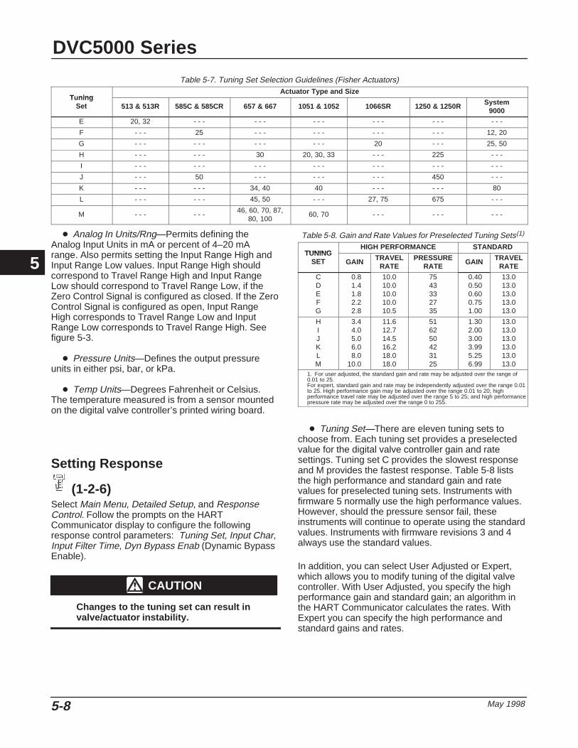
DVC5000 Series
May 19985-8
Table 5-7. Tuning Set Selection Guidelines (Fisher Actuators)
T ningActuator Type and Size
TuningSet 513 & 513R 585C & 585CR 657 & 667 1051 & 1052 1066SR 1250 & 1250R System
9000
E 20, 32 - - - - - - - - - - - - - - - - - -
F - - - 25 - - - - - - - - - - - - 12, 20
G - - - - - - - - - - - - 20 - - - 25, 50
H - - - - - - 30 20, 30, 33 - - - 225 - - -
I - - - - - - - - - - - - - - - - - - - - -
J - - - 50 - - - - - - - - - 450 - - -
K - - - - - - 34, 40 40 - - - - - - 80
L - - - - - - 45, 50 - - - 27, 75 675 - - -
M - - - - - - 46, 60, 70, 87,80, 100
60, 70 - - - - - - - - -
� Analog In Units/Rng—Permits defining theAnalog Input Units in mA or percent of 4–20 mArange. Also permits setting the Input Range High andInput Range Low values. Input Range High shouldcorrespond to Travel Range High and Input RangeLow should correspond to Travel Range Low, if theZero Control Signal is configured as closed. If the ZeroControl Signal is configured as open, Input RangeHigh corresponds to Travel Range Low and InputRange Low corresponds to Travel Range High. Seefigure 5-3.
� Pressure Units—Defines the output pressureunits in either psi, bar, or kPa.
� Temp Units—Degrees Fahrenheit or Celsius.The temperature measured is from a sensor mountedon the digital valve controller’s printed wiring board.
Setting Response
(1-2-6)Select Main Menu, Detailed Setup, and ResponseControl. Follow the prompts on the HARTCommunicator display to configure the followingresponse control parameters: Tuning Set, Input Char,Input Filter Time, Dyn Bypass Enab (Dynamic BypassEnable).
CAUTION
Changes to the tuning set can result invalve/actuator instability.
Table 5-8. Gain and Rate Values for Preselected Tuning Sets(1)
TUNINGHIGH PERFORMANCE STANDARD
TUNINGSET GAIN TRAVEL
RATEPRESSURE
RATEGAIN TRAVEL
RATE
CDEFG
0.81.41.82.22.8
10.010.010.010.010.5
7543332735
0.400.500.600.751.00
13.013.013.013.013.0
HIJKLM
3.44.05.06.08.0
10.0
11.612.714.516.218.018.0
516250423125
1.302.003.003.995.256.99
13.013.013.013.013.013.0
1. For user adjusted, the standard gain and rate may be adjusted over the range of0.01 to 25.For expert, standard gain and rate may be independently adjusted over the range 0.01to 25. High performance gain may be adjusted over the range 0.01 to 20; highperformance travel rate may be adjusted over the range 5 to 25; and high performancepressure rate may be adjusted over the range 0 to 255.
� Tuning Set—There are eleven tuning sets tochoose from. Each tuning set provides a preselectedvalue for the digital valve controller gain and ratesettings. Tuning set C provides the slowest responseand M provides the fastest response. Table 5-8 liststhe high performance and standard gain and ratevalues for preselected tuning sets. Instruments withfirmware 5 normally use the high performance values.However, should the pressure sensor fail, theseinstruments will continue to operate using the standardvalues. Instruments with firmware revisions 3 and 4always use the standard values.
In addition, you can select User Adjusted or Expert,which allows you to modify tuning of the digital valvecontroller. With User Adjusted, you specify the highperformance gain and standard gain; an algorithm inthe HART Communicator calculates the rates. WithExpert you can specify the high performance andstandard gains and rates.
5

Detailed Setup
May 1998 5-9
Table 5-9. Tuning Set Selection Guidelines (BaumannActuators)
TuningAct ator Size
TuningSet Actuator Size
E 32
H 54
K 70
Table 5-10. Tuning Set Selection Guidelines (Gulde Actuators)
TUNING ACTUATOR TYPE AND SIZETUNINGSET 3024 3025
E GA 1.21 - - -
H GA 1.31 - - -
K GA 1.41 - - -
M - - - P460, P462, P900
Table 5-11. Tuning Set Selection Guidelines (Other Actuators)ACTUATOR TYPE AND SIZE
TUNINGSET Neles-Jamesbury
Quadra-Power IIMasoneilanCamflex II
MasoneilanSigma F,
Minitorque, &Ball II
D - - - 4.5 A
H QP2, QP3 6 or 7 B
I - - - - - - - - -
J QP4 - - - - - -
K QP5 - - - C
To setup an instrument with firmware 5 to respondsimilar to an instrument with firmware 4, select Expertthen adjust the high performance gain and travel rateto match the standard gain and travel rate. Set thehigh performance pressure rate to zero.
NoteFor Firmware Revision 3, only the eleventuning sets are available. User adjusted orExpert tuning is not available.
Table 5-7 provides tuning set selection guidelines forFisher Controls actuators. Tables 5-9 through 5-11 listtuning set guidelines for Baumann, Gulde, and otheractuators. These tuning sets are only recommendedstarting points. After you finish setting up andcalibrating the instrument, you may have to selecteither a higher or lower tuning set to get the desiredresponse.
For an actuator not listed in the tables, you canestimate a starting tuning set by calculating the casingor cylinder volume. Then, in the tables, find an
actuator with the closest equivalent volume and usethe tuning set suggested for that actuator.
� Input Char—Defines the relationship between theranged travel and ranged set point. Ranged setpoint isthe input to the characterization function. If the zerocontrol signal equals closed, then a setpoint of 0%corresponds to a ranged input of 0%. If the zerocontrol signal equals open, a setpoint of 0%corresponds to a ranged input of 100%. Ranged travelis the output from the characterization function.
You can select from the three fixed inputcharacteristics shown in Figure 5-2 or, for instrumentswith firmware revision 5, you can select a customcharacteristic. Figure 5-2 shows the relationshipbetween the ranged travel and ranged set point for thefixed input characteristics, assuming the Zero ControlSignal is configured as closed.
For instruments with firmware revision 5, you canspecify 37 points on a custom characteristic curve.Each point defines a travel target, in % of rangedtravel, for a corresponding ranged set point, in % ofranged set point. Set point values range from –6.25%to 106.25% in 3.125% increments. Beforemodification, the custom characteristic is linear.
To define a custom input characteristic, from the InputChar menu select Define Custom Char. Select thepoint you wish to define (1 to 37), then enter thedesired ranged travel value corresponding to theranged set point. When finished, select point 0 toreturn to the Input Char menu.
With input characterization you can modify the overallcharacteristic of the valve and instrument combination.Selecting an equal percentage, quick opening, orcustom (other than the default of linear) inputcharacteristic modifies the overall valve andinstrument characteristic. However, if you select thelinear input characteristic, the overall valve andinstrument characteristic is the characteristic of thevalve, which is determined by the valve trim (i.e., theplug or cage).
The factory default setting for input characterization islinear.
� Input Filter Time—Time constant for the inputfilter, in seconds. The input filter slows the response ofthe digital valve controller and is typically used withnoisy or fast processes. The filter provides improvedclosed loop process control. Generally, an input filter isnot required if dynamic bypass is enabled. To disablethe filter, set the time constant to 0 seconds.
� Dyn Bypass Enab—Yes or No. GenerallyDynamic Bypass is not required if the input filter isused. With Dynamic Bypass enabled, the instrumentdynamic response to input changes will be similar to
5

DVC5000 Series
May 19985-10
Ran
ged
Trav
el, %
Ranged Set Point, %–25 0 125100
–25 0 125100
–25 0 125100
Input Characteristic = Linear
Input Characteristic = Equal Percentage
Input Characteristic = Quick Opening
100
0
–25
125
Ran
ged
Trav
el, %
100
0
–25
125
Ranged Set Point, %
Ran
ged
Trav
el, %
100
0
–25
125
Ranged Set Point, %
A6535-1/IL
Figure 5-2. Ranged Travel Versus Ranged Set Point, forVarious Input Characteristics (Zero Control Signal = Closed)
the first order lag exhibited by a Fisher Controls Type546 I/P transducer connected directly to a largevolume spring and diaphragm actuator.
This provides dampening to the final control elementand can stabilize some process loops. It is generallybeneficial in fast process loops and will improveprocess control. (See Fisher Controls technicalmonograph TM-36 for further discussion ofpositioner/booster guidelines.)
Position feedback to the instrument is maintained withDynamic Bypass enabled. Static performance is notaffected.
� Min Opening Time—Minimum Opening Time isconfigured in seconds and defines the minimum timefor the travel to increase the entire ranged travel. Thisrate is applied to any travel increases. A value of 0.0seconds deactivates this feature and allows the valveto stroke open as fast as possible.
� Min Closing Time—Minimum Closing Time isconfigured in seconds and defines the minimum timefor the travel to decrease the entire ranged travel. Thisrate is applied to any travel decreases. A value of 0.0seconds deactivates this feature and allows the valveto stroke closed as fast as possible.
Travel Ranges, Limits, and
Cutoffs
Setting Travel Ranges
(1-2-5)Select Main Menu, Detailed Setup, and Measured Var.Follow the prompts on the HART Communicatordisplay to set the Tvl Range High (Travel Range High),and Tvl Range Low (Travel Range Low).
NoteFor Firmware Revision 5, the Travel RangeHigh and Low values are preset in theinstrument. Changing the Travel RangeHigh and Low values has no effect. TravelRange High is set at 100%; Travel RangeLow is set at 0%.
5
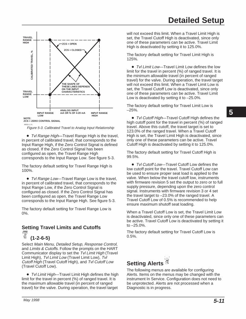
Detailed Setup
May 1998 5-11
TRAVELRANGEHIGH
TRAVELRANGELOW
THE SHAPE OFTHESE LINES DEPENDSON THE INPUTCHARACTERISTICS
INPUT RANGE LOW
INPUT RANGE HIGH
ANALOG INPUTmA OR % OF 4-20 mA
CA
LIB
RAT
ED
TR
AVE
L, %
A6531-1 / IL
Figure 5-3. Calibrated Travel to Analog Input Relationship
ZCS = CLOSED
ZCS = OPEN
NOTE:ZCS = ZERO CONTROL SIGNAL
� Tvl Range High—Travel Range High is the travel,in percent of calibrated travel, that corresponds to theInput Range High, if the Zero Control Signal is definedas closed. If the Zero Control Signal has beenconfigured as open, the Travel Range Highcorresponds to the Input Range Low. See figure 5-3.
The factory default setting for Travel Range High is100%.
� Tvl Range Low—Travel Range Low is the travel,in percent of calibrated travel, that corresponds to theInput Range Low, if the Zero Control Signal isconfigured as closed. If the Zero Control Signal hasbeen configured as open, the Travel Range Lowcorresponds to the Input Range High. See figure 5-3.
The factory default setting for Travel Range Low is0%.
Setting Travel Limits and Cutoffs
(1-2-6-5)Select Main Menu, Detailed Setup, Response Control,and Limits & Cutoffs. Follow the prompts on the HARTCommunicator display to set the Tvl Limit High (TravelLimit High), Tvl Limit Low (Travel Limit Low), TvlCutoff High (Travel Cutoff High), and Tvl Cutoff Low(Travel Cutoff Low).
� Tvl Limit High—Travel Limit High defines the highlimit for the travel in percent (%) of ranged travel. It isthe maximum allowable travel (in percent of rangedtravel) for the valve. During operation, the travel target
will not exceed this limit. When a Travel Limit High isset, the Travel Cutoff High is deactivated, since onlyone of these parameters can be active. Travel LimitHigh is deactivated by setting it to 125.0%.
The factory default setting for Travel Limit High is125%.
� Tvl Limit Low—Travel Limit Low defines the lowlimit for the travel in percent (%) of ranged travel. It isthe minimum allowable travel (in percent of rangedtravel) for the valve. During operation, the travel targetwill not exceed this limit. When a Travel Limit Low isset, the Travel Cutoff Low is deactivated, since onlyone of these parameters can be active. Travel LimitLow is deactivated by setting it to –25.0%.
The factory default setting for Travel Limit Low is–25%.
� Tvl Cutoff High—Travel Cutoff High defines thehigh cutoff point for the travel in percent (%) of rangedtravel. Above this cutoff, the travel target is set to123.0% of the ranged travel. When a Travel CutoffHigh is set, the Travel Limit High is deactivated, sinceonly one of these parameters can be active. TravelCutoff High is deactivated by setting it to 125.0%.
The factory default setting for Travel Cutoff High is99.5%.
� Tvl Cutoff Low—Travel Cutoff Low defines thelow cutoff point for the travel. Travel Cutoff Low canbe used to ensure proper seat load is applied to thevalve. When below the travel cutoff low, instrumentswith firmware revision 5 set the output to zero or to fullsupply pressure, depending upon the zero controlsignal. Instruments with firmware revision 3 or 4 setthe travel target to –23.0% of the ranged travel. ATravel Cutoff Low of 0.5% is recommended to helpensure maximum shutoff seat loading.
When a Travel Cutoff Low is set, the Travel Limit Lowis deactivated, since only one of these parameters canbe active. Travel Cutoff Low is deactivated by setting itto –25.0%.
The factory default setting for Travel Cutoff Low is0.5%.
Setting AlertsThe following menus are available for configuringAlerts. Items on the menus may be changed with theinstrument In Service. Configuration does not need tobe unprotected. Alerts are not processed when aDiagnostic is in progress.
5

DVC5000 Series
May 19985-12
NoteAlerts are not available with instrumentlevel HC.
NoteFor Firmware Revision 3, alerts are notprocessed if the instrument is Out ofService.
Setting Travel Alerts
(1-2-7-1)
Setting Alerts 1 and 2Select Main Menu, Detailed Setup, Alerts, and TravelAlerts. Follow the prompts on the HARTCommunicator display to set: Tvl Alrt 1 Enab (TravelAlert 1 Enable), Tvl Alrt 2 Enab (Travel Alert 2Enable), Tvl Alrt 1 High Pt (Travel Alert 1 High Point),Tvl Alrt 1 Low Pt (Travel Alert 1 Low Point), Tvl Alrt 2High Pt (Travel Alert 2 High Point), Tvl Alrt 2 Low Pt(Travel Alert 2 Low Point), and Tvl Alrt DB (TravelAlert Deadband).
� Tvl Alrt 1 Enab—Yes or No. Travel Alert 1Enable activates checking of the ranged travel againstthe Travel Alert 1 High and Low Points. Travel Alert 1is set if either the high or low point is exceeded. Oncea high or low point is exceeded, the ranged travel mustclear that point by the Travel Alert Deadband beforethe alert is cleared. See figure 5-4.
� Tvl Alrt 2 Enab—Yes or No. Travel Alert 2Enable activates checking of the ranged travel againstthe Travel Alert 2 High and Low Points. Travel Alert 2is set if either the high or low point is exceeded. Oncea high or low point is exceeded, the ranged travel mustclear that point by the Travel Alert Deadband beforethe alert is cleared. See figure 5-4.
� Tvl Alrt 1 High Pt—Travel Alert 1 High Point isthe value of the travel, in percent (%) of ranged travel,
ALERT IS CLEARED
ALERT IS SET
TRAVEL ALERTHIGH POINT
TRAVEL ALERTDEADBAND
A6532/IL
Figure 5-4. Travel Alert Deadband
which, when exceeded, sets the Travel Alert 1 Highalert.
� Tvl Alrt 1 Low Pt—Travel Alert 1 Low Point is thevalue of the travel, in percent (%) of ranged travel,which, when exceeded, sets the Travel Alert 1 Lowalert.
� Tvl Alrt 2 High Pt—Travel Alert 2 High Point isthe value of the travel, in percent (%) of ranged travel,which, when exceeded, sets the Travel Alert 2 Highalert.
� Tvl Alrt 2 Low Pt—Travel Alert 2 Low Point is thevalue of the travel, in percent (%) of ranged travel,which, when exceeded, sets the Travel Alert 2 Lowalert.
� Tvl Alrt DB—Travel Alert Deadband is the travel,in percent (%) of ranged travel, required to clear atravel alert, once it has been set. The deadbandapplies to both Travel Alert 1 and Travel Alert 2. Seefigure 5-4.
NoteFor Firmware Revision 3, the Travel AlertDeadband applies to the Travel Deviationas well as Travel Alert 1 and Travel Alert 2.
Setting Travel Deviation Alert
(1-2-7-2)Select Main Menu, Detailed Setup, Alerts, and TravelDev Alert. Follow the prompts on the HARTCommunicator display to configure the following: TvlDev Alrt Enab (Travel Deviation Alert Enable), Tvl Dev
5

Detailed Setup
May 1998 5-13
Alrt Pt (Travel Deviation Alert Point), and Tvl DevTime (Travel Deviation Time).
� Tvl Dev Alrt Enab—Yes or No. Travel DeviationAlert Enable activates checking of the differencebetween the target and the ranged travel. If thedifference exceeds the Travel Deviation Alert Point formore than the Travel Deviation Time, the TravelDeviation Alert is set. It remains set until the differenceis less than the Travel Deviation Alert Point.
NoteFor Firmware Revision 3, the TravelDeviation Alert remains set until the Traveldifference between the target and theranged travel is less than the TravelDeviation Alert Point minus the TravelAlert Deadband.
� Tvl Dev Alrt Pt—Travel Deviation Alert Point isthe alert point for the difference, expressed in percent(%), between the targeted travel and the rangedtravel. When the difference exceeds the alert point formore than the Travel Deviation Time, the TravelDeviation Alert is set.
� Tvl Dev Time—Travel Deviation Time is the time,in seconds, that the travel must exceed the TravelDeviation Alert Point before the alert is set.
Setting Travel Accumulation Alert
(1-2-7-3)Select Main Menu, Detailed Setup, Alerts, and TravelAccum Alert. Follow the prompts on the HARTCommunicator display to configure the following: TvlAcum Alrt Enab (Travel Accumulator Alert Enable), TvlAcum DB (Travel Accumulator Deadband), Tvl AcumAlrt Pt (Travel Accumulator Alert Point), Tvl Acum(Travel Accumulator).
� Tvl Acum Alrt Enab—Yes or No. TravelAccumulator Alert Enable activates checking of thedifference between the Travel Accumulator value andthe Travel Accumulator Alert Point. The TravelAccumulator Alert is set when the Travel Accumulatorvalue exceeds the Travel Accumulator Alert Point. It iscleared after you reset the Travel Accumulator to avalue less than the alert point.
Deadband Reference
Deadband (+/– 5%)
Deadband exceeded,new Reference Pointestablished
Point
This amount of change isadded to the TravelAccumulator.
A6534/IL
Figure 5-5. Travel Accumulator Deadband (set at 10%)
� Tvl Acum DB—Travel Accumulator Deadband isthe area around the travel reference point, in percent(%) of ranged travel, that was established at the lastincrement of the accumulator. This area must beexceeded before a change in travel can beaccumulated. See figure 5-5.
� Tvl Acum Alrt Pt—Travel Accumulator Alert Pointis the value of the Travel Accumulator, in percent (%)of ranged travel, which, when exceeded, sets theTravel Accumulator Alert.
� Tvl Acum—Travel Accumulator records the totalchange in travel, in percent (%) of ranged travel, sincethe accumulator was last cleared. The value of theTravel Accumulator increments when the magnitude ofthe change exceeds the Travel Accumulator Dead-band. See figure 5-5. You can reset the TravelAccumulator by configuring it to zero.
Cycle Counter Alert
(1-2-7-4)Select Main Menu, Detailed Setup, Alerts, and CycleCount Alert. Follow the prompts on the HARTCommunicator display to configure the following: CyclCnt Alrt Enab (Cycle Counter Alert Enable), CyclCount DB (Cycle Counter Deadband), Cycl Count AlrtPt (Cycle Counter Alert Point), Cycl Count (CycleCounter).
� Cycl Cnt Alrt Enab—Yes or No. Cycle CounterAlert Enable activates checking of the differencebetween the Cycle Counter and the Cycle CounterAlert point. The Cycle Counter Alert is set when thevalue exceeds the Cycle Counter Alert point. It iscleared after you reset the Cycle Counter to a valueless than the alert point.
5

DVC5000 Series
May 19985-14
Deadband Reference
Deadband (+/– 5%)
Deadband exceeded, and directionchanged, new Reference Pointestablished
Point
Point at whichcycle is counted.
A6533-1/IL
Figure 5-6. Cycle Counter Deadband (set at 10%)
� Cycl Count DB—Cycle Counter Deadband is thearea around the travel reference point, in percent (%)of ranged travel, that was established at the lastincrement of the Cycle Counter. This area must beexceeded before a change in travel direction can becounted as a cycle. See figure 5-6.
� Cycl Count Alrt Pt—Cycle Counter Alert Point isthe value of the Cycle Counter, in cycles, which, whenexceeded, sets the Cycle Counter Alert.
� Cycle Count—Cycle Counter records the numberof times the travel changes direction. The change indirection must occur after the deadband has beenexceeded before it can be counted as a cycle. Seefigure 5-6. You can reset the Cycle Counter byconfiguring it as zero.
Drive Alert Enable
(1-2-7-5)Select Main Menu, Detailed Setup, Alerts, and DriveAlert Enab. Follow the prompts on the HARTCommunicator display to configure the drive signalalert.
� Drive Alrt Enab—Yes or No. Drive Alert Enableactivates checking of the relationship between theDrive Signal and the calibrated travel. If one of thefollowing conditions exists for more than 20 seconds,the Drive Alert is set.
For the case where Zero Control Signal is defined asclosed:
Drive Signal < 10% and Calibrated Travel > 3%
Drive Signal > 90% and Calibrated Travel < 97%
For the case where Zero Control Signal is defined asopen:
Drive Signal < 10% and Calibrated Travel < 97%
Drive Signal > 90% and Calibrated Travel > 3%
Miscellaneous Alerts
(1-2-7-6)Select Main Menu, Detailed Setup, Alerts, and MiscAlerts. Follow the prompts on the HARTCommunicator display to configure the Aux In AlrtEnab (Auxiliary Input Alert Enable) and Aux In AlrtState (Auxilliary Input Alert State).
� Aux In Alrt Enab—Yes or No. Auxiliary Input AlertEnable activates checking the status of the auxiliaryinput, which is a contact or discrete input. Whenenabled, the Auxiliary Input Alert is set when theauxiliary input terminals are either open or closed,depending upon the selection for the Aux In Alrt State.
� Aux In Alrt State—Open or Closed. Determineswhich state of the contacts (open or closed) connectedto the auxiliary input terminals causes the auxiliaryinput alert to be active.
Alert Record
(1-2-7-7)Firmware revision 5 instruments have an alert recordthat can store alerts from any of the enabled alertgroups: Valve Alerts, Failure Alerts or MiscellaneousAlerts. Select Main Menu, Detailed Setup, Alerts, andAlert Record. Follow the prompts on the HARTCommunicator display to Display Record, ClearRecord, set the Inst Date & Time (Instrument Dateand Time), and enable Record Groups.
Alert Record is only available for instruments withfirmware revision 5.
� Display Record —Displays all recorded alertsand the date and time the alerts were recorded.
� Clear Record —Clears the alert record. To clearthe alert record, all alerts in enabled groups must beinactive.
� Inst Date and Time —Permits setting theinstrument clock. When alerts are stored in the alertrecord, the date and time (obtained from theinstrument clock) that they were stored is also storedin the record.
5

Detailed Setup
May 1998 5-15
� Record Groups —Permits enabling one or morealert groups. Table 5-12 lists the alerts included ineach of the groups. When any alert from an enabledgroup becomes active, active alerts in all enabledgroups are stored.
Table 5-12. Alerts Included in Alert Groups for Alert RecordAlert Group Alerts Include in Group
Valve Alerts
Travel 1 lowTravel 1 highTravel 2 lowTravel 2 highTravel deviationDrive signal
Failure Alerts(1)
No free timeRAM failDrive current failNVM failTemperature sensor failPressure sensor failTravel sensor fail
Miscellaneous Alerts Auxiliary input1. The Failure Alerts group is only available for instruments with firmware revision 5in hardware revision 5.
Self Test Failures for Instrument
Shutdown (1-2-8) Select Main Menu, Detailed Setup, and Self TestShutdown. Follow the prompts on the HART
Communicator display to determine the self testshutdown criteria from the following selections: Done,No Free Time Fail (No Free Time Failure), RAM Fail(Random Access Memory Failure), Critical NVM Fail(Critical Non-Volatile Memory Failure), Temp SensorFail (Temperature Sensor Failure),Tvl Sensor Fail(Travel Sensor Failure), or Drive Current Fail. Upon
shutdown, the instrument attempts to drive its outputpressure to the zero current condition and no longerexecutes its control function. In addition, theappropriate failure statuses are set. Once the problemthat caused the shutdown has been fixed, theinstrument can be restarted by cycling the power orselecting Restart from the Mode menu of the HARTCommunicator. Also see the DVC5000 Series DigitalValve Controller Instrument Status section on page7-3 for further details about failures.
� Done—Select this if you are done modifying theself test shutdown criteria.
� No Free Time Fail—When enabled, theinstrument shuts down whenever there is a failureassociated with No Free Time.
� RAM Fail—When enabled, the instrument shutsdown whenever there is a failure associated with RAM(random access memory).
� Critical NVM Fail—When enabled, the instrumentshuts down whenever there is a failure associated withcritical NVM (non-volatile memory).
� Temp Sensor Fail—When enabled, theinstrument shuts down whenever there is a failureassociated with the internal temperature sensor.
� Tvl Sensor Fail—When enabled, the instrumentshuts down whenever there is a failure associated withthe travel sensor.
� Drive Current Fail—When enabled, theinstrument shuts down whenever the drive currentdoes not match the drive signal. Drive Current Fail isonly available with instrument firmware revision 5 inhardware revision 5.
5
DVC5000 Series
May 19985-16
5

Calibration
May 1998 6-1
6-6
Section 6 Calibration
Restoring Calibration to Factory Settings 6-2. . . . . . . . . . . . . . . . . . . . . . . . . . . . .
Analog Input Calibration 6-2. . . . . . . . . . . . . . . . . . . . . . . . . . . . . . . . . . . . . . . . . . . . . . . .
Auto Calibrate Travel 6-3. . . . . . . . . . . . . . . . . . . . . . . . . . . . . . . . . . . . . . . . . . . . . . . . . . .
Manual Calibrate Travel 6-4. . . . . . . . . . . . . . . . . . . . . . . . . . . . . . . . . . . . . . . . . . . . . . . .
Pressure Sensor Calibration 6-6. . . . . . . . . . . . . . . . . . . . . . . . . . . . . . . . . . . . . . . . . . .
Travel Sensor Adjust 6-6. . . . . . . . . . . . . . . . . . . . . . . . . . . . . . . . . . . . . . . . . . . . . . . . . . .
DVC5010 Digital Valve Controllers 6-6. . . . . . . . . . . . . . . . . . . . . . . . . . . . . . . . . . . . . . . .
DVC5020 Digital Valve Controllers 6-7. . . . . . . . . . . . . . . . . . . . . . . . . . . . . . . . . . . . . . . .
DVC5030 Digital Valve Controllers on Fisher Actuators 6-6. . . . . . . . . . . . . . . . . . . .
DVC5030 Digital Valve Controllers on Other Actuators 6-8. . . . . . . . . . . . . . . . . . . . .
DVC5040 Digital Valve Controllers 6-6. . . . . . . . . . . . . . . . . . . . . . . . . . . . . . . . . . . . . . . .
6
DVC5000 Series
May 19986-2
When a DVC5000 Series digital valve controller isordered as part of a control valve assembly, thefactory mounts the digital valve controller on theactuator and connects the necessary tubing, then setsup and calibrates the controller.
For digital valve controllers that are orderedseparately, recalibration of the analog input orpressure sensors generally is unnecessary. However,after mounting on an actuator, perform the initial setup(either auto or manual) then calibrate travel byselecting Auto Calib Travel from the Auto Setup orManual Setup menus. For more detailed calibrationinformation, refer to the following calibrationprocedures, available from the Calibrate menu:
� Analog Input —This procedure permitscalibrating the analog input sensor.
� Auto Calibrate Travel —This procedureautomatically calibrates the travel. The calibrationprocedure uses the valve and actuator stops as the0% and 100% calibration points.
� Manual Calibrate Travel —This procedurepermits manual calibration of the travel. Thiscalibration procedure allows you to determine the 0%and 100% calibration points.
� Pressure Sensor —This procedure permitscalibrating the pressure sensor.
� Restore Calibration —This procedure permitsyou to restore the calibration settings back to thefactory settings.
� Calibrate Location —Indicates the location ofthe last instrument calibration. The calibration locationis either FACTORY or FIELD. A new instrument willdisplay FACTORY. As soon as calibration isperformed on one of the measured variables, such asAnalog Input, Travel, or if the tuning set is changed,the Calibration Location is set to FIELD. When youselect Restore Calib, under the Calibrate menu, thecalibration parameters are reset to the original factorysettings.
� Travel Sensor Adjust —This procedure permitscalibrating the travel sensor.
To display the calibrate menu, select Calibrate fromthe Main Menu.
NoteThe Instrument Mode must be Out OfService and the Protection set to Nonebefore the instrument can be calibrated.
WARNING
During calibration, the valve maymove. To avoid personal injury andproperty damage caused by the re-lease of pressure or process fluid,provide some temporary means ofcontrol for the process.
Restoring Calibration to Factory
Settings (1-4-5)Select Main Menu, Calibrate, and Restore Calib.Follow the prompts on the HART Communicatordisplay to restore calibration to the factory settings.You should only restore the calibration if it is notpossible to calibrate an individual sensor. Restoringcalibration returns the calibration of all of the sensorsand the tuning set to their factory settings. Followingrestoration of the factory calibration, the individualsensors should be recalibrated.
Analog Input Calibration (1-4-1) To calibrate the analog input sensor, connect avariable current source to the instrument terminalslabeled LOOP+ and LOOP–. The current sourceshould be capable of generating an output of 4 to 20mA. Select Analog In from the Calibrate menu, thenfollow the prompts on the HART Communicatordisplay to calibrate the analog input sensor.
1. Set the current source to the target value shown onthe display. The target value is the Input Range Lowvalue. Press OK.
2. The following message appears:
6

Calibration
May 1998 6-3
Use Increase andDecrease selectionsuntil the displayedcurrent matches thetarget.
Press OK when you have read this message.
3. The value of the Analog Input appears on thedisplay. Press OK to display the adjustment menu.
4. From the adjustment menu, select the direction andsize of adjustment to the displayed value. Selectinglarge, medium, and small adjustments causeschanges of approximately 0.4 mA, 0.04 mA, and 0.004mA, respectively. If the displayed value does notmatch the current source, press OK, then repeat thisstep (step 4) to further adjust the displayed value.When the displayed value matches the current source,select Done and go to step 5.
5. Set the current source to the target value shown onthe display. The target value is the Input Range Highvalue. Press OK.
6. The following message appears:
Use Increase andDecrease selectionsuntil the displayedcurrent matches thetarget.
Press OK when you have read this message.
7. The value of the Analog Input appears on thedisplay. Press OK to display the adjustment menu.
8. From the adjustment menu, select the direction andsize of adjustment to the displayed value. Selectinglarge, medium, and small adjustments causeschanges of approximately 0.4 mA, 0.04 mA, and 0.004mA, respectively. If the displayed value does notmatch the current source, press OK, then repeat thisstep (step 8) to further adjust the displayed value.When the displayed value matches the current source,select Done and go to step 9.
9. Place the instrument In Service and verify that theanalog input displayed matches the current source.
Auto Calibrate Travel (1-4-2) User interaction is only required with Auto CalibrateTravel when the feedback characteristic issliding-stem. A feedback characteristic of rotaryrequires no user interaction and you can start with
A6536/IL
Figure 6-1. Crossover Point
step 4. For a sliding-stem feedback characteristic,interaction provides a more accurate crossoveradjustment. Select Auto Calib Travel from theCalibrate menu, then follow the prompts on the HARTCommunicator display to automatically calibrate travel.
1. Select the method of crossover adjustment:manual, last value, or default.
If you select Last Value, the crossover settingcurrently stored in the instrument is used and thereare no further user interactions with theauto-calibration routine (go to step 4). If you selectDefault, an approximate value for the crossover iswritten to the instrument and there are no further userinteractions with the auto-calibration routine (go tostep 4). If you select Manual, you are asked to selectan adjustment source, either analog or digital.
If you use a current source to adjust the crossover,select Analog and go to step 2. If you wish to adjustthe current source digitally, select Digital and go tostep 3.
2. If you selected Analog as the crossover adjustmentsource, the HART Communicator prompts you toadjust the current source until the feedback arm is 90°to the actuator stem, as shown in figure 6-1. After youhave made the adjustment, press OK and go to step4.
3. If you selected Digital as the crossover adjustmentsource, the HART Communicator displays a menu toallow you to adjust the crossover.
Select the direction and size of change required to setthe feedback arm so it is 90° to the actuator stem, asshown in figure 6-1. Selecting large, medium, andsmall adjustments to the crossover causes changes of
6
DVC5000 Series
May 19986-4
approximately 10.0°, 1.0°, and 0.1°, respectively, tothe rotation of the feedback arm.
If another adjustment is required, repeat step 3.Otherwise, select Done and go to step 4.
4. The remainder of the auto calibration procedure isautomatic. It is completed when the Calibrate menuappears
5. Place the instrument In Service and verify that thetravel properly tracks the current source.
Manual Calibrate Travel (1-4-3) Two procedures are available to manually calibratetravel:
� Analog Calibration Adjust
� Digital Calibration Adjust
Analog Calibration Adjust (1-4-3-1) Select Main Menu, Calibrate, Man Calib Travel, andAnalog Calib Adj. Connect a variable current source tothe instrument termination LOOP + and LOOP –. Thecurrent source should be capable of generating 4 to 20mA. Follow the prompts on the HART Communicatordisplay to calibrate the instrument’s travel in percent.
NoteFor firmware revisions 3 and 4, config-ure the Travel Range High at 100% andTravel Range Low at 0% before cali-brating. If the travel is to be sub-ranged, change Travel Range High andLow after completing the travel calibra-tion.
Note0% Travel = Valve Closed100% Travel = Valve Open
1. For firmware revisions 4 and 5, adjust the inputcurrent until the valve moves. Then, reduce the inputcurrent until the output pressure is 0. Press OK.
2. If the feedback characteristic is specified as rotary,go to step 6. If the feedback characteristic is specifiedas sliding-stem, you are prompted to set the crossoverpoint. Adjust the current source until the feedback armis 90° to the actuator stem, as shown in figure 6-1.Then press OK.
3. Adjust the current source until the valve is at 0%travel, then press OK.
4. Adjust the current source until the valve is at 100%travel, then press OK.
5. Adjust the current source until the valve is at 50%travel, then press OK.
6. Adjust the current source until the valve is at 0%travel, then press OK.
7. Adjust the current source until the valve is at 100%travel, then press OK.
8. Steps 9 and 10 repeat some of the above steps tofurther improve the accuracy of the calibration.
9. Adjust the current source until the valve is at 0%travel, then press OK.
10. Adjust the current source until the valve is at100% travel, then press OK.
11. Place the instrument In Service and verify that thetravel properly tracks the current source.
Digital Calibration Adjust (1-4-3-2) Select Main Menu, Calibrate, Man Calib Travel, andDigital Calib Adj. Connect a variable current source tothe instrument LOOP + and LOOP – terminals. Thecurrent source should be set between 4 and 20 mA.Follow the prompts on the HART Communicatordisplay to calibrate the instrument’s travel in percent.
NoteFor firmware revisions 3 and 4, config-ure the Travel Range High at 100% andTravel Range Low at 0% before cali-brating. If the travel is to be sub-ranged, change Travel Range High andLow after completing the travel calibra-tion.
6
Calibration
May 1998 6-5
Note0% Travel = Valve Closed100% Travel = Valve Open
1. For firmware revisions 4 and 5, from theadjustment menu, select the direction and size ofchange required to adjust the output until the valvemoves. Selecting large, medium, and smalladjustments causes changes of approximately 10.0°,1.0°, and 0.1°, respectively, to the feedback armrotation.
If another adjustment is required, repeat step 1.Otherwise, reduce the output pressure to 0, selectDone and go to step 2.
2. If the feedback characteristic is specified as rotary,go to step 8. If the feedback characteristic is specifiedas sliding-stem, adjust the feedback arm to thecrossover point by pressing OK to get to theadjustment menu.
3. From the adjustment menu, select the direction andsize of change required to set the feedback arm so itis 90° to the actuator stem, as shown in figure 6-1.Selecting large, medium, and small adjustments to thecrossover causes changes of approximately 10.0°,1.0°, and 0.1°, respectively, to the feedback armrotation.
If another adjustment is required, repeat step 3.Otherwise, select Done and go to step 3.
4. The following message appears.
Adjust travel to theindicated value usingthe menu selections.
Press OK to display the adjustment menu.
5. From the adjustment menu, select the direction andsize of change required to set the travel at 0%.Selecting large, medium, and small adjustmentscauses changes of approximately 10.0°, 1.0°, and0.1°, respectively, to the feedback arm rotation for asliding-stem valve or to the travel for a rotary valve.
If another adjustment is required, repeat step 5.Otherwise, select Done and go to step 6.
6. From the adjustment menu, select the direction andsize of change required to set the travel to 100%.Selecting large, medium, and small adjustmentscauses changes of approximately 10.0°, 1.0°, and0.1°, respectively, to the feedback arm rotation for asliding-stem valve or to the travel for a rotary valve.
If another adjustment is required, repeat step 6.Otherwise, select Done and go to step 7.
7. From the adjustment menu, select the direction andsize of change required to set the travel to 50%.Selecting large, medium, and small adjustmentscauses changes of approximately 10.0°, 1.0°, and0.1°, respectively, to the feedback arm rotation for asliding-stem valve or to the travel for a rotary valve.
If another adjustment is required, repeat step 7.Otherwise, select Done and go to step 8.
8. From the adjustment menu, select the direction andsize of change required to set the travel to 0%.Selecting large, medium, and small adjustmentscauses changes of approximately 10.0°, 1.0°, and0.1°, respectively, to the feedback arm rotation for asliding-stem valve or to the travel for a rotary valve.
If another adjustment is required, repeat step 8.Otherwise, select Done and go to step 9.
9. From the adjustment menu, select the direction andsize of change required to set the travel to 100%.Selecting large, medium, and small adjustmentscauses changes of approximately 10.0°, 1.0°, and0.1°, respectively, to the feedback arm rotation for asliding-stem valve or to the travel for a rotary valve.
If another adjustment is required, repeat step 9.Otherwise, select Done and go to step 10.
10. From the adjustment menu, select the directionand size of change required to set the travel to 0%.Selecting large, medium, and small adjustmentscauses changes of approximately 10.0°, 1.0°, and0.1°, respectively, to the feedback arm rotation for asliding-stem valve or to the travel for a rotary valve.
If another adjustment is required, repeat step 10.Otherwise, select Done and go to step 11.
11. From the adjustment menu, select the directionand size of change required to set the travel to 100%.Selecting large, medium, and small adjustmentscauses changes of approximately 10.0°, 1.0°, and0.1°, respectively, to the feedback arm rotation for asliding-stem valve or to the travel for a rotary valve.
If another adjustment is required, repeat step 11.Otherwise, select Done and go to step 12.
12. Place the instrument In Service and verify that thetravel properly tracks the current source.
6

DVC5000 Series
May 19986-6
Pressure Sensor Calibration
(1-4-4) Select Main Menu, Calibrate, and Pressure. Follow theprompts on the HART Communicator display tocalibrate the instrument’s output pressure sensor.
1. Adjust the supply pressure regulator until theoutput pressure matches the target value shown onthe display. Press OK.
2. The following message appears.
Use the Increase andDecrease selectionsuntil the displayedpress matches thetarget.
Press OK when you have read this message.
3. The value of the pressure appears on the display.Press OK to display the adjustment menu.
4. From the adjustment menu, select the direction andsize of adjustment to the displayed value. Selectinglarge, medium, and small adjustments causeschanges of approximately 3.0 psi/0.207 bar/20.7 kPa,0.30 psi/0.0207 bar/2.07 kPa, and 0.03 psi/0.00207bar/0.207 kPa, respectively. If the displayed valuedoes not match the supply pressure, press OK, thenrepeat this step (step 4) to further adjust the displayedvalue. When the displayed value matches the supplypressure, select Done and go to step 5.
5. Set the supply pressure to the target value shownon the display. Press OK.
6. The following message appears.
Use the Increase andDecrease selectionsuntil the displayedpress matches thetarget.
Press OK when you have read this message.
7. The value of the pressure appears on the display.Press OK to display the adjustment menu.
8. From the adjustment menu, select the direction andsize of adjustment to the displayed value. Selectinglarge, medium, and small adjustments causeschanges of approximately 3.0 psi/0.207 bar/20.7 kPa,0.30 psi/0.0207 bar/2.07 kPa, and 0.03 psi/0.00207bar/0.207 kPa, respectively. If the displayed valuedoes not match the supply pressure, press OK, thenrepeat this step (step 8) to further adjust the displayed
value. When the displayed value matches the supplypressure, select Done and go to step 9.
9. Place the instrument In Service and verify that thedisplayed pressure matches the measured outputpressure.
Travel Sensor Adjust (1-4-7)
DVC5010, DVC5030 on Fisher Actuators,and DVC5040 Digital Valve Controllers The travel sensor is normally adjusted at the factoryand should not require adjustment. However, if thetravel sensor has been replaced, adjust the travelsensor by performing the following procedure. See theMaintenance section, Section 9 for travel sensorreplacement procedures.
1. Remove supply air and remove the instrument fromthe actuator.
NoteThe alignment pin (key 46) is stored insidethe digital valve controller housing. It islocated above the supply pressure gauge.
2. As shown in figure 6-2, align the feedback arm (key79) with the housing by inserting the alignment pin(key 46) through the hole marked “A” on the feedbackarm. Fully engage the alignment pin into the tappedhole in the housing. Position the feedback arm so thatthe surface with the travel markings is flush with theend of the travel sensor shaft.
3. Loosen the screw that secures the feedback arm tothe travel sensor shaft.
4. Connect a current source to the instrument LOOP– and LOOP + terminals. Set the current source toany value between 4 and 20 mA. Connect the HARTCommunicator to the TALK terminals.
5. Before beginning the travel sensor adjustment, setthe instrument mode to Out Of Service and theprotection to None.
6. Select Main Menu, Display, Device Information,and Hardware Revision. Note the hardware revisionnumber.
7. Select Main Menu, Calibrate, Tvl Sensor Adjust.Follow the prompts on the HART Communicatordisplay to adjust the travel sensor counts to the valuelisted in table 6-1.
6
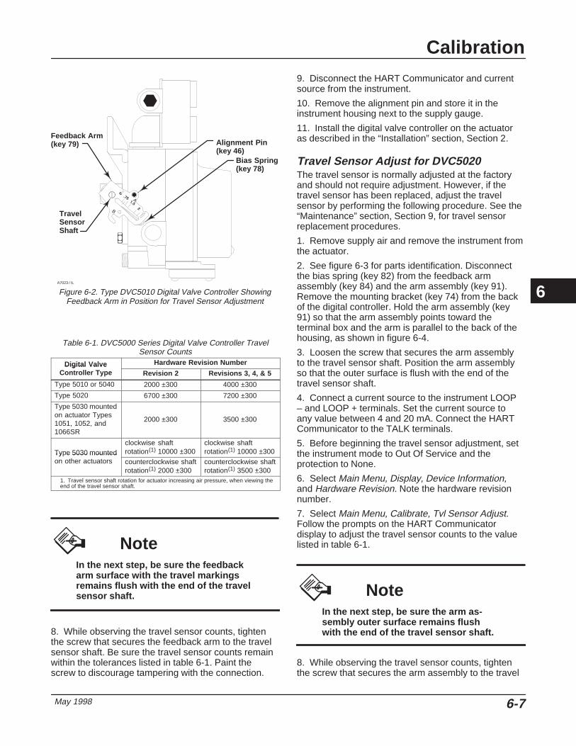
Calibration
May 1998 6-7
Figure 6-2. Type DVC5010 Digital Valve Controller ShowingFeedback Arm in Position for Travel Sensor Adjustment
Feedback Arm(key 79)
A
BTravel SensorShaft
Alignment Pin(key 46)
Bias Spring(key 78)
A7023 / IL
Table 6-1. DVC5000 Series Digital Valve Controller TravelSensor Counts
Digital Valve Hardware Revision NumberDigital ValveController Type Revision 2 Revisions 3, 4, & 5
Type 5010 or 5040 2000 ±300 4000 ±300
Type 5020 6700 ±300 7200 ±300
Type 5030 mountedon actuator Types1051, 1052, and1066SR
2000 ±300 3500 ±300
Type 5030 mountedclockwise shaftrotation(1) 10000 ±300
clockwise shaftrotation(1) 10000 ±300Ty e 5030 mounted
on other actuators counterclockwise shaftrotation(1) 2000 ±300
counterclockwise shaftrotation(1) 3500 ±300
1. Travel sensor shaft rotation for actuator increasing air pressure, when viewing theend of the travel sensor shaft.
NoteIn the next step, be sure the feedbackarm surface with the travel markingsremains flush with the end of the travelsensor shaft.
8. While observing the travel sensor counts, tightenthe screw that secures the feedback arm to the travelsensor shaft. Be sure the travel sensor counts remainwithin the tolerances listed in table 6-1. Paint thescrew to discourage tampering with the connection.
9. Disconnect the HART Communicator and currentsource from the instrument.
10. Remove the alignment pin and store it in theinstrument housing next to the supply gauge.
11. Install the digital valve controller on the actuatoras described in the “Installation” section, Section 2.
Travel Sensor Adjust for DVC5020 The travel sensor is normally adjusted at the factoryand should not require adjustment. However, if thetravel sensor has been replaced, adjust the travelsensor by performing the following procedure. See the“Maintenance” section, Section 9, for travel sensorreplacement procedures.
1. Remove supply air and remove the instrument fromthe actuator.
2. See figure 6-3 for parts identification. Disconnectthe bias spring (key 82) from the feedback armassembly (key 84) and the arm assembly (key 91).Remove the mounting bracket (key 74) from the backof the digital controller. Hold the arm assembly (key91) so that the arm assembly points toward theterminal box and the arm is parallel to the back of thehousing, as shown in figure 6-4.
3. Loosen the screw that secures the arm assemblyto the travel sensor shaft. Position the arm assemblyso that the outer surface is flush with the end of thetravel sensor shaft.
4. Connect a current source to the instrument LOOP– and LOOP + terminals. Set the current source toany value between 4 and 20 mA. Connect the HARTCommunicator to the TALK terminals.
5. Before beginning the travel sensor adjustment, setthe instrument mode to Out Of Service and theprotection to None.
6. Select Main Menu, Display, Device Information,and Hardware Revision. Note the hardware revisionnumber.
7. Select Main Menu, Calibrate, Tvl Sensor Adjust.Follow the prompts on the HART Communicatordisplay to adjust the travel sensor counts to the valuelisted in table 6-1.
NoteIn the next step, be sure the arm as-sembly outer surface remains flushwith the end of the travel sensor shaft.
8. While observing the travel sensor counts, tightenthe screw that secures the arm assembly to the travel
6

DVC5000 Series
May 19986-8
Figure 6-3. Type DVC5020 Digital Valve Controller Mounted on Type 1052, Size 33 Actuator
MOUNTINGADAPTER(KEY 117)
FEEDBACK ARM ASSEMBLY(KEY 84)FEEDBACK ARM
TORSION SPRING(KEY 93)
BIAS SPRING(KEY 82)
ARM ASSEMBLY PIN
ARM ASSEMBLY(KEY 91)
MOUNTING BRACKET(KEY 74)
CAP SCREW, HEX SOCKET(KEY 116)
CAP SCREW, HEX HEAD(KEY 92)
A7024 / IL
TRAVEL SENSORSHAFT
Figure 6-4. Type DVC5020 Travel Sensor Arm/Housing BackPlane Alignment
ARM ASSEMBLY
BACK OF HOUSING
ARM ASSEMBLY PIN
BACK EDGEOF ARM PARALLELW/BACK OF HOUSING
A7025 / IL
sensor shaft. Be sure the travel sensor counts remain
within the tolerances listed in table 6-1. Paint thescrew to discourage tampering with the connection.
9. Disconnect the HART Communicator and currentsource from the instrument.
10. Apply lubricant (key 63) to the pin portion of thearm assembly (key 91).
11. Replace the mounting bracket on the back of theinstrument and reconnect the bias spring between thefeedback arm assembly and the arm assembly on thetravel sensor shaft.
12. Install the digital valve controller on the actuatoras described in the “Installation” section, Section 2.
Travel Sensor Adjust for DVC5030 onOther Actuators Travel sensor adjustment is part of the installationprocedure when installing the Type DVC5030 digitalvalve controller on other than Fisher actuators. Installthe digital valve controller as described in the
6
Calibration
May 1998 6-9
“Installation” section, Section 2. When you are readyto perform the step that requires travel sensoradjustment, perform the following procedure:
1. Connect a current source to the instrument LOOP– and LOOP + terminals. Set the current source toany value between 4 and 20 mA. Connect the HARTCommunicator to the TALK terminals.
2. Before beginning the travel sensor adjustment, setthe instrument mode to Out Of Service and theprotection to None.
3. Select Main Menu, Display, Device Information,and Hardware Revision. Note the hardware revisionnumber.
4. Select Main Menu, Calibrate, Tvl Sensor Adjust.Follow the prompts on the HART Communicatordisplay to adjust the travel sensor counts to the valuelisted in table 6-1. Note the travel sensor shaft rotationwith increasing air pressure and adjust the travelsensor counts accordingly.
5. Tighten the coupler set screw to secure the couplerto the shaft connector cap pin, tie bar assembly, orspindle. If the coupler set screw is not accessible dueto obstructions, loosen the coupler set screw on thetravel sensor shaft and rotate the coupler. Then,tighten the coupler set screw and repeat step 4.
6. After completing the travel sensor adjustment,perform the remainder of the installation procedure inthe “Installation” section.
6

DVC5000 Series
May 19986-10
6

Viewing Device Information
May 1998 7-1
7-7
Section 7 Viewing Device Information
Variables 7-2. . . . . . . . . . . . . . . . . . . . . . . . . . . . . . . . . . . . . . . . . . . . . . . . . . . . . . . . . . . . . . . . .
Analog Input 7-2. . . . . . . . . . . . . . . . . . . . . . . . . . . . . . . . . . . . . . . . . . . . . . . . . . . . . . . . . . . . .
Output Pressure 7-2. . . . . . . . . . . . . . . . . . . . . . . . . . . . . . . . . . . . . . . . . . . . . . . . . . . . . . . . .
Drive Signal 7-2. . . . . . . . . . . . . . . . . . . . . . . . . . . . . . . . . . . . . . . . . . . . . . . . . . . . . . . . . . . . .
Additional Instrument Variables 7-2. . . . . . . . . . . . . . . . . . . . . . . . . . . . . . . . . . . . . . . . . . . Auxiliary InputInternal TemperatureCycle CountTravel AccumulatorFree TimeTravel Sensor Counts
Device Information 7-3. . . . . . . . . . . . . . . . . . . . . . . . . . . . . . . . . . . . . . . . . . . . . . . . . . . . . .
HART Universal Revision
Interface Revision
Firmware Revision
Hardware Revision
Output Bias Revised?
Advanced Diagnostics
Instrument Level
Pressure Sensor
Device Identifier
Instrument Status 7-3. . . . . . . . . . . . . . . . . . . . . . . . . . . . . . . . . . . . . . . . . . . . . . . . . . . . . . .
Valve Alerts
Failure Alerts
Alert Record
Operational Status
7

DVC5000 Series
May 19987-2
The following menus are available to define and/orview information about the instrument.
Viewing Variables
Analog Input, Output Pressure, Travel,and Drive Signal
NoteThese variables are not available forinstrument level AC.
The following variables are displayed on the Onlinemenu:
Analog In shows the value of the instrument analoginput in mA (milliamperes) or % (percent) of rangedinput.
Press shows the value of the instrument outputpressure in psi, bar, or kPa.
Travel shows the value of the DVC5000 Series digitalvalve controller travel in % (percent) of ranged travel.Travel always represents how far the valve is open.
Drive Sgl shows the value of the instrument drivesignal in % (percent) of maximum drive.
Additional Instrument Variables
(1-3-1)
NoteThese variables are not available forinstrument level AC.
The Variables menu is available to view additionalvariables, such as the status of the auxiliary input, theinstrument internal temperature, cycle count, travelaccumulation, device free time, and travel sensorcounts. To view one of these variables, from theOnline menu select Main Menu, Display, andVariables. If a value for a variable does not appear on
the display, select the variable and a detail display ofthat variable with its value will appear. A variable’svalue does not appear on the menu if the valuebecomes too large to fit in the allocated space on thedisplay, or the variable requires special processing,such as Free Time or Aux In.
� Aux In—The Auxiliary Input is a discrete inputthat can be used with an independent limit or pressureswitch. Its value is either open or closed.
� Temp—The internal temperature of theinstrument is displayed in either degrees Fahrenheit orCelsius.
� Cycl Count—Cycle Counter displays the numberof times the instrument has cycled. Only changes indirection of the travel after the travel has exceeded thedeadband are counted as a cycle. Once a new cyclehas occurred, a new deadband around the last travelis set. The value of the Cycle Counter can be resetfrom the Cycle Count Alert menu. See Cycle CounterDeadband in Section 5 for more details.
� Tvl Acum—Travel Accumulator contains the totalchange in travel, in percent of ranged travel. Theaccumulator only increments when travel exceeds thedeadband. Then the greatest amount of change in onedirection from the original reference point (after thedeadband has been exceeded) will be added to theTravel Accumulator. The value of the TravelAccumulator can be reset from the Travel Accum Alertmenu. See Travel Accumulator Deadband in Section 5for more details.
� Free Time—Free Time is the percent of time thatthe firmware is idle. A typical value is 25%. The actualvalue depends on the number of functions in theinstrument that are enabled and also on the amount ofcommunication currently in progress.
NoteDo not use the the following travelsensor counts indication for calibrat-ing the travel sensor. The followingshould only be used for a relative indi-cation to be sure the travel sensor isworking and that it is moving in thecorrect direction. Perform the TravelSensor Adjust procedure in Section 6to calibrate the travel sensor.
� Tvl Sens Cts—Travel Sensor Counts indicatesthe travel sensor position in analog-to-digital converter
7
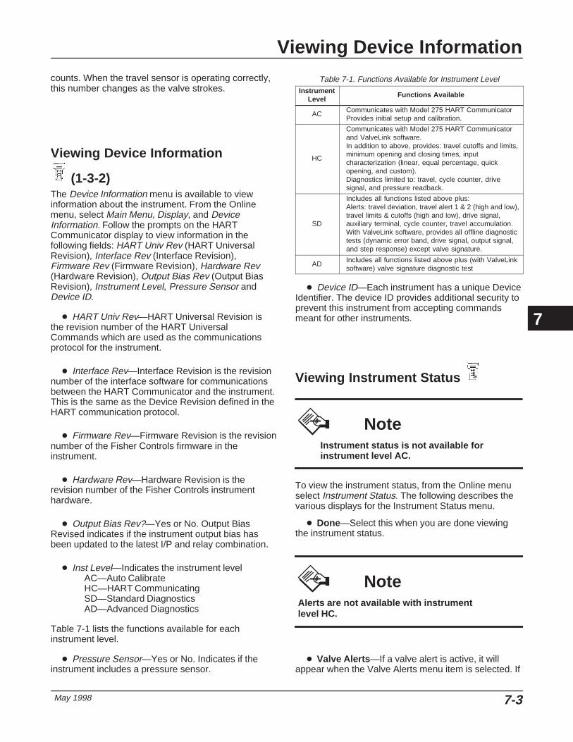
Viewing Device Information
May 1998 7-3
counts. When the travel sensor is operating correctly,this number changes as the valve strokes.
Viewing Device Information
(1-3-2) The Device Information menu is available to viewinformation about the instrument. From the Onlinemenu, select Main Menu, Display, and DeviceInformation. Follow the prompts on the HARTCommunicator display to view information in thefollowing fields: HART Univ Rev (HART UniversalRevision), Interface Rev (Interface Revision),Firmware Rev (Firmware Revision), Hardware Rev(Hardware Revision), Output Bias Rev (Output BiasRevision), Instrument Level, Pressure Sensor andDevice ID.
� HART Univ Rev—HART Universal Revision isthe revision number of the HART UniversalCommands which are used as the communicationsprotocol for the instrument.
� Interface Rev—Interface Revision is the revisionnumber of the interface software for communicationsbetween the HART Communicator and the instrument.This is the same as the Device Revision defined in theHART communication protocol.
� Firmware Rev—Firmware Revision is the revisionnumber of the Fisher Controls firmware in theinstrument.
� Hardware Rev—Hardware Revision is therevision number of the Fisher Controls instrumenthardware.
� Output Bias Rev?—Yes or No. Output BiasRevised indicates if the instrument output bias hasbeen updated to the latest I/P and relay combination.
� Inst Level—Indicates the instrument levelAC—Auto CalibrateHC—HART CommunicatingSD—Standard DiagnosticsAD—Advanced Diagnostics
Table 7-1 lists the functions available for eachinstrument level.
� Pressure Sensor—Yes or No. Indicates if theinstrument includes a pressure sensor.
Table 7-1. Functions Available for Instrument LevelInstrument
LevelFunctions Available
AC Communicates with Model 275 HART CommunicatorProvides initial setup and calibration.
HC
Communicates with Model 275 HART Communicatorand ValveLink software.In addition to above, provides: travel cutoffs and limits,minimum opening and closing times, inputcharacterization (linear, equal percentage, quickopening, and custom).Diagnostics limited to: travel, cycle counter, drivesignal, and pressure readback.
SD
Includes all functions listed above plus:Alerts: travel deviation, travel alert 1 & 2 (high and low),travel limits & cutoffs (high and low), drive signal,auxiliary terminal, cycle counter, travel accumulation.With ValveLink software, provides all offline diagnostictests (dynamic error band, drive signal, output signal,and step response) except valve signature.
AD Includes all functions listed above plus (with ValveLinksoftware) valve signature diagnostic test
� Device ID—Each instrument has a unique DeviceIdentifier. The device ID provides additional security toprevent this instrument from accepting commandsmeant for other instruments.
Viewing Instrument Status
NoteInstrument status is not available forinstrument level AC.
To view the instrument status, from the Online menuselect Instrument Status. The following describes thevarious displays for the Instrument Status menu.
� Done—Select this when you are done viewingthe instrument status.
NoteAlerts are not available with instrumentlevel HC.
� Valve Alerts —If a valve alert is active, it willappear when the Valve Alerts menu item is selected. If
7
DVC5000 Series
May 19987-4
more than one alert is active, they will appear on thedisplay one at a time in the order listed below.
1. Non-critical NVM Alert
2. Cycle Counter Alert
3. Tvl Accumulation Alert
4. Aux Terminal Alert
5. Tvl Alrt 1-High Alrt
6. Tvl Alrt 1-Low Alrt
7. Tvl Alrt 2-High Alrt
8. Tvl Alrt 2-Low Alrt
9. Tvl Deviation Alrt
10. Tvl Lim/Cutoff High
11. Tvl Lim/Cutoff Low
12. Drive Signal Alert
� Failure Alerts —If a self-test failure hasoccurred, it will appear when the Failure Alerts menuitem is selected. If there are multiple failures, they willappear on the display one at a time in the order listedbelow.
1. Offline/Failed—This failure is indicated when afailure, enabled from the Self Test Shutdown menu,causes an instrument shutdown. Press Enter to seewhich of the specific failures caused the Offline/Failedindication.
2. No Free Time—This failure is indicated if theinstrument is unable to complete all of the configuredtasks. This will not occur with a properly functioninginstrument.
3. RAM Fail—This failure is indicated when theRandom Access Memory integrity test fails. Dynamicdata is stored in RAM. If this failure is indicated,restart the instrument and see if it clears. If it does notclear, replace the PWB Assembly.
4. Drive Current Fail—This failure is indicated whenthe drive current does not match the drive signal. Ifthis failure occurs, check the connection between theI/P converter and the pwb assembly. Try removing theI/P converter and re-installing it. If the failure does notclear, replace the I/P converter or the pwb assembly.
5. Critical NVM Alert—This failure is indicated whenthe Non-Volatile Memory integrity test fails.Configuration data is stored in NVM. If this failure isindicated, restart the instrument and see if it clears. Ifit does not clear, replace the PWB Assembly.
6. Temperature Sensor Fail—This failure is indicatedwhen the instrument temperature sensor fails, or thesensor reading is outside of the range of –40 to 176�F(–40 to 80�C). The temperature reading is usedinternally for temperature compensation of inputs. Ifthis failure is indicated, restart the instrument and seeif it clears. If it does not clear, replace the PWBAssembly.
7. Pressure Sensor Fail—This failure is indicatedwhen the actuator pressure is outside the range of–24.0 to 125.0% of the calibrated pressure for morethan 60 seconds. If this failure is indicated, check theinstrument supply pressure. If the failure persists,ensure the PWB assembly is properly mounted ontothe Module Base Assembly, and the pressure sensorO-ring is properly installed. If the failure does not clearafter restarting the instrument, replace the PWBAssembly.
8. Travel Sensor Fail—This failure is indicated whenthe sensed travel is outside of the range of –25.0 to125.0% of the calibrated travel. If this failure isindicated, check the instrument mounting and thetravel sensor adjustment. Also, check that theelectrical connection from the travel sensor is properlyplugged into the PWB assembly. After restarting theinstrument, if the failure does not clear, replace thePWB Assembly.
� Alert Record —Firmware revision 5 instrumentshave an alert record that can store alerts from any ofthe enabled alert groups: Valve Alerts, Failure Alertsor Miscellaneous Alerts. Table 7-2 lists the alertsincluded in each of the groups. The alert record alsoincludes the date and time (from the instrument clock)the alert occurred.
� Operational Status —This menu item indicatesthe status of the Operational items listed below. Thestatus of more than one operational may be indicated.If more than one Operational status is set, they willappear on the display one at a time in the order listedbelow.
1. Out of Service
2. Input Char Selected
3. Custom Char Selected
4. High Performance in Effect
5. Diagnostic in Progress
6. Calibration in Progress
7. Dynamic Bypass Enabled
8. Calib—Valve Cntrl Inactive
9. Burst Mode is Enabled
7

Viewing Device Information
May 1998 7-5
Table 7-2. Alerts Included in Alert Groups for Alert RecordAlert Group Alerts Include in Group
Valve Alerts
Travel 1 lowTravel 1 highTravel 2 lowTravel 2 highTravel deviationDrive signal
Failure Alerts(1)
No free timeRAM failDrive current failNVM failTemperature sensor failPressure sensor failTravel sensor fail
Miscellaneous Alerts Auxiliary input1. The Failure Alerts group is only available for instruments with firmware revision 5in hardware revision 5.
7

DVC5000 Series
May 19987-6
7

Principle of Operation
May 1998 8-1
8-8
Section 8 Principle of Operation
HART Communication 8-2. . . . . . . . . . . . . . . . . . . . . . . . . . . . . . . . . . . . . . . . . . . . . . . . . .
Digital Valve Controller Operation 8-2. . . . . . . . . . . . . . . . . . . . . . . . . . . . . . . . . . . . .
8

DVC5000 Series
May 19988-2
Figure 8-1. HART� Frequency Shift Keying Technique
–0.5 mA
+0.5 mA
1200 Hz“1”
2200 Hz“0”
AVERAGE CURRENT CHANGE DURING COMMUNICATION = 0
ANALOGSIGNAL
0
A6174/IL
HART Communication The HART (Highway Addressable RemoteTransducer) protocol gives field devices the capabilityof communicating instrument and process datadigitally. This digital communication occurs over thesame two-wire loop that provides the 4–20 mAprocess control signal, without disrupting the processsignal. In this way, the analog process signal, with itsfaster update rate, can be used for control. At thesame time, the HART protocol allows access to digitaldiagnostic, maintenance, and additional process data.The protocol provides total system integration via ahost device.
The HART protocol uses the frequency shift keying(FSK) technique based on the Bell 202 communicationstandard. By superimposing a frequency signal overthe 4–20 mA current, digital communication isattained. Two individual frequencies of 1200 and 2200Hz are superimposed as a sinewave over the 4–20mA current loop. These frequencies represent thedigits 1 and 0 (see figure 8-1). The average value ofthis sinewave is zero, therefore no dc value is addedto the 4–20 mA signal. Thus, true simultaneouscommunication is achieved without interrupting theprocess signal.
The HART protocol allows the capability ofmultidropping, networking several devices to a singlecommunications line. This process is well suited formonitoring remote applications such as pipelines,custody transfer sites, and tank farms. See table 9-2for instructions on changing the mode switchconfiguration to multidrop.
Digital Valve Controller Operation DVC5000 Series digital valve controllers have a singlemaster module that may be easily replaced in the fieldwithout disconnecting field wiring or tubing. Thismaster module contains the following submodules: I/P
Figure 8-2. Typical FIELDVUE Instrument to PersonalComputer Connections for ValveLink Type VL2010 or VL2020
Software
FIELDTERM.
CONTROL SYSTEM
HARTMODEM
A6761 / IL
converter, printed wiring board (printed wiring board)assembly, and pneumatic relay. The master modulecan be rebuilt by replacing the submodules. Seefigures 8-3 and 8-4.
DVC5000 Series digital valve controllers areloop-powered instruments that provide a control valveposition proportional to an input signal from the controlroom. The following describes a direct acting TypeDVC5010 digital valve controller mounted on a Type657 actuator.
The input signal is routed into the terminal box througha single twisted pair of wires and then to the printedwiring board assembly submodule where it is read bythe microprocessor, processed by a digital algorithm,and converted into an analog I/P drive signal.
As the input signal increases, the drive signal to theI/P converter increases. This makes the magneticattraction between the core and armature of the I/Pconverter increase, causing the flapper to restrict thenozzle, which increases the nozzle pressure. Thenozzle pressure is routed to the input diaphragm of thepneumatic relay submodule. As the nozzle pressureincreases, the pneumatic relay diaphragm assemblymoves, causing the valve plug to open the supply portand close the exhaust port, increasing the outputpressure to the actuator. The increased outputpressure causes the actuator stem to movedownward. Stem position is sensed through thefeedback linkage by the travel sensor which is
8

Principle of Operation
May 1998 8-3
Figure 8-3. DVC5000 Series Digital Valve Controller Principle of Operation
AUXILIARYTERMINALS
4–20 mA+HART
INPUTSIGNAL
PRINTEDWIRING BOARD
SUPPLYPRESSURE
PRESSURESENSOR FORADVANCEDDIAGNOSTICS I/P
RELAYOUTPUT
PRESSURE
STEMFEEDBACK
A6480-1/IL
Figure 8-4. DVC5000 Series Digital Valve Controller Assembly
TERMINAL BOX COVER(KEY 4)
TERMINAL BOXASSEMBLY(KEY 164)
HOUSING(KEY 1)
GASKET(KEY 42)
PRINTED WIRING BOARDASSEMBLY (KEY 50)
RELAY(KEY 24)
RELAY CAP(KEY 26)
I/P CONVERTER(KEY 41)
MODULE BASE ASSEMBLY(KEY 20)
PRESSURE GAUGES(KEY 47)
TRAVEL SENSORASSEMBLY (KEY77)
COVER ASSEMBLY(KEY 43)
A7026 / IL
electrically connected to the printed wiring boardassembly submodule. The stem continues to movedownward until the correct stem position is attained. Atthis point the printed wiring board assembly stabilizesthe I/P drive signal. This positions the flapper toprevent any further increase in nozzle pressure.
As the input signal decreases, the drive signal to theI/P converter submodule decreases, decreasing thenozzle pressure. The pneumatic relay diaphragmassembly moves, causing the valve plug to close thesupply port and open the exhaust port, releasing theactuator casing pressure to atmosphere. The stem
8

DVC5000 Series
May 19988-4
Figure 8-5. Typical FIELDVUE Instrument to Personal Computer Connections for ValveLink Type VL2030 Software
CONTROL SYSTEMRS-232/485
CONVERTER
HART INTERCHANGE
FIELDTERM.
A6760 / IL
moves upward until the correct position is attained. Atthis point the printed wiring board assembly stabilizesthe I/P drive signal. This positions the flapper toprevent any further decrease in nozzle pressure.
8

Maintenance
May 1998 9-1
9-9
Section 9 Maintenance
Stroking the Digital Valve Controller Output
Using the 275 HART Communicator 9-3. . . . . . . . . . . . . . . . . . . . . . . . . . . . . . . . . . . . . .
Manually Stroking the Output 9-3. . . . . . . . . . . . . . . . . . . . . . . . . . . . . . . . . . . . . . . . . . . . .
Instrument Troubleshooting 9-3. . . . . . . . . . . . . . . . . . . . . . . . . . . . . . . . . . . . . . . . . . . .
Checking Voltage Available 9-3. . . . . . . . . . . . . . . . . . . . . . . . . . . . . . . . . . . . . . . . . . . .
Master Module Maintenance
Removing the Master Module 9-5. . . . . . . . . . . . . . . . . . . . . . . . . . . . . . . . . . . . . . . . . . . . .
Replacing the Master Module 9-6. . . . . . . . . . . . . . . . . . . . . . . . . . . . . . . . . . . . . . . . . . . . .
SubModule Maintenance
I/P ConverterClearing the Primary Orifice 9-7. . . . . . . . . . . . . . . . . . . . . . . . . . . . . . . . . . . . . . . . . . . . . . . Manual Output Test 9-7. . . . . . . . . . . . . . . . . . . . . . . . . . . . . . . . . . . . . . . . . . . . . . . . . . . . . . Removing the I/P Converter 9-7. . . . . . . . . . . . . . . . . . . . . . . . . . . . . . . . . . . . . . . . . . . . . . . Replacing the I/P Converter 9-7. . . . . . . . . . . . . . . . . . . . . . . . . . . . . . . . . . . . . . . . . . . . . . .
Printed Wiring Board (PWB) AssemblyRemoving the Printed Wiring Board Assembly 9-8. . . . . . . . . . . . . . . . . . . . . . . . . . . . . . . . Replacing the Printed Wiring Board Assembly 9-8. . . . . . . . . . . . . . . . . . . . . . . . . . . . . . . . Setting the Mode Switches 9-8. . . . . . . . . . . . . . . . . . . . . . . . . . . . . . . . . . . . . . . . . . . . . . . .
Pneumatic RelayRemoving the Pneumatic Relay 9-8. . . . . . . . . . . . . . . . . . . . . . . . . . . . . . . . . . . . . . . . . . . . Replacing the Pneumatic Relay 9-9. . . . . . . . . . . . . . . . . . . . . . . . . . . . . . . . . . . . . . . . . . . .
Gauges, Pipe Plugs or Tire Valves 9-10. . . . . . . . . . . . . . . . . . . . . . . . . . . . . . . . . . . . . . . .
Terminal Box
Removing the Terminal Box 9-10. . . . . . . . . . . . . . . . . . . . . . . . . . . . . . . . . . . . . . . . . . . . . .
Replacing the Terminal Box 9-10. . . . . . . . . . . . . . . . . . . . . . . . . . . . . . . . . . . . . . . . . . . . . .
Travel Sensor
DisassemblyDVC5010 Digital Valve Controller (Sliding-Stem) 9-11. . . . . . . . . . . . . . . . . . . . . . . . . . . . . . DVC5020 Digital Valve Controller (Rotary) 9-11. . . . . . . . . . . . . . . . . . . . . . . . . . . . . . . . . . . DVC5030 Digital Valve Controller (Rotary) 9-11. . . . . . . . . . . . . . . . . . . . . . . . . . . . . . . . . . . DVC5040 Digital Valve Controller (Sliding-Stem) 9-11. . . . . . . . . . . . . . . . . . . . . . . . . . . . . .
9

DVC5000 Series
May 19989-2
AssemblyDVC5010 Digital Valve Controller (Sliding-Stem) 9-11. . . . . . . . . . . . . . . . . . . . . . . . . . . . . . DVC5020 Digital Valve Controller (Rotary) 9-13. . . . . . . . . . . . . . . . . . . . . . . . . . . . . . . . . . . DVC5030 Digital Valve Controller (Rotary) 9-14. . . . . . . . . . . . . . . . . . . . . . . . . . . . . . . . . . . DVC5040 Digital Valve Controller (Sliding-Stem) 9-11. . . . . . . . . . . . . . . . . . . . . . . . . . . . . .
9

Maintenance
May 1998 9-3
NoteIf the feedback arm (key 79) or feedbackarm assembly (key 84) is removed fromthe DVC5000 Series digital valve control-ler, the travel sensor (key 77) must be re-calibrated.
Because of the diagnostic capability of the DVC5000Series digital valve controllers, predictive maintenanceis available through the use of FIELDVUE ValveLinkSoftware. Using the digital valve controller, valve andinstrument maintenance can be enhanced, thusavoiding unnecessary maintenance. For informationon using the ValveLink software, see the FIELDVUEValveLink VL2000 Series Software User Guide.
Stroking the Digital Valve ControllerOutput
Stroking the Output Using the 275 HARTCommunicator
(1-5)
NoteStroke output is not available with in-strument level AC.
From the Online menu, select Main Menu and StrokeOutput. Follow the prompts on the HARTCommunicator display to select from the following:Done, Ramp Open, Ramp Closed, Ramp to Target,Step to Target, and Stop.
� Done—Select this if you are done. All ramping isstopped when DONE is selected.
� Ramp Open—ramps the travel toward open atthe rate of 1.0% per second of the ranged travel.
� Ramp Closed—ramps the travel toward closed atthe rate of 1.0% per second of the ranged travel.
� Ramp to Target—ramps the travel to thespecified target at the rate of 1.0% per second of theranged travel.
� Step to Target—steps the travel to the specifiedtarget.
� Stop—stops the command.
Manually Stroking the Output Refer to figure 9-1.
To increase output pressure, depress the I/Parmature by gently pressing on the flapper mountingscrew. After viewing the output pressure, gently lift theI/P armature by lifting on the flapper mounting screwto return the output pressure to its original value.
To decrease output pressure, gently lift the I/Parmature by lifting on the flapper mounting screw.After viewing the output pressure, press on the flappermounting screw slightly to return the output pressureto its original value.
Instrument Troubleshooting If communication or output difficulties are experiencedwith the instrument, refer to the troubleshooting chartshown in table 9-1.
Checking Voltage Available
WARNING
Personal injury or property damagecaused by fire or explosion may occurif this test is attempted in an areawhich contains a potentially explosiveatmosphere or has been classified ashazardous.
To check the Voltage Available at the instrument,perform the following:
1. Connect the equipment in figure 2-22 to the fieldwiring in place of the FIELDVUE instrument.
2. Set the control system to provide maximum outputcurrent.
3. Set the resistance of the 1 kilohm potentiometershown in figure 2-22 to zero.
9

DVC5000 Series
May 19989-4
Table 9-1. Instrument Troubleshooting Symptom Possible Cause Action
1. Instrument will not communicate. 1a. Insufficient Voltage Available. 1a. Calculate Voltage Available (see Wiring Practicesin the “Installation” section, Section 2). VoltageAvailable should be greater than or equal to 12 Vdc.
1b. Controller output Impedance too low. 1b. Install a HART filter after reviewing ControlSystem Compliance Voltage requirements (see WiringPractices in the “Installation” section, Section 2).
1c. Cable capacitance too high. 1c. Review maximum cable capacitance limits (seeWiring Practices in the “Installation” section, Section2).
1d. HART filter improperly adjusted. 1d. Check filter adjustment (see the appropriate HART filter instruction manual).
1e. Improper field wiring. 1e. Check polarity of wiring and integrity ofconnections. Make sure cable shield is grounded only at the control system.
1f. Controller output providing less than 4 mA to loop. 1f. Check control system minimum output setting,which should not be less than 3.8 mA.
1g. Disconnected loop wiring cable at PWB. 1g. Verify connectors are plugged in correctly.
1h. PWB DIP switches not set properly. 1h. Check for incorrect setting or broken DIP switches on the back of the PWB. Reset switches or replace PWB, if switches are broken. See table 9-2 for switch setting information
1j. PWB failure. 1j. Use a 4–20 mA current source to apply power tothe instrument. Terminal voltage across the LOOP+and LOOP– terminals should be 10 to 11.5 Vdc. If the terminal voltage is not 10 to 11.5 Vdc; over100mA has been applied to the input terminals.Replace the PWB.
1k. Polling address incorrect. 1k. Use the HART Communicator to set the pollingaddress (refer to the Detailed Setup section, Section5). From the Utilities menu, select Always Poll. Setthe polling address to 0.
1l. Defective cable from terminal box. 1l. Check cable continuity. If necessary, replace theterminal box assembly.
1m. Defective terminal box assembly printed wiringboard.
1m Check for damaged printed wiring board lands and terminals. If necessary, replace the terminal box assembly.
1n. Defective HART Communicator or ValveLinkmodem cable.
1n. If necessary, repair or replace cable.
1p. ValveLink modem defective or not compatible withPC.
1p. Replace ValveLink modem.
1q. ValveLink hardlock defective or not programmed. 1q. Replace if defective or return to factory forprogramming.
2. Instrument will not calibrate,has sluggish performance or oscillates.
2a. Travel sensor “frozen”, will not turn. 2a. Rotate feedback arm to ensure it moves freely. Ifnot, replace the pot/bushing assy.gg
2b. Broken travel sensor wire(s). 2b. Inspect wires for broken solder joint at potor broken wire. Replace pot/bushing assy.
2c. Travel sensor mis-adjusted. 2c. Perform Travel Sensor Adjust procedure in“Calibration” section, Section 6.
2d. Open travel sensor. 2d. Check for continuity in electrical travel range. Ifnecessary, replace pot/bushing assy.
2e. Cables not plugged into PWB correctly. 2e. Inspect connections and correct.
2f. Feedback arm loose on pot. 2f. Perform Travel Sensor Adjust procedure in“Calibration” section, Section 6.
2g. Feedback arm bent/damaged or bias springmissing/damaged.
2g. Replace feedback arm and bias spring.
–continued–
9

Maintenance
May 1998 9-5
Table 9-1. Instrument Troubleshooting (Continued)Symptom ActionPossible Cause
2h. Configuration errors. 2h. Verify configuration:If necessary, set protection to None.If Out of Service, place In Service.Check:Invert feedback.Tuning setZero control signalFeedback characteristicControl mode (should be RSP)Restart control mode (should be RSP)Tvl Range Low and High
2j. I/P assy primary restriction plugged. 2j. Apply supply pressure and depress cleanout wire.
2k. Air blockage in I/P assy nozzle block, not clearedby depressing cleanout wire.
2k. Replace I/P assy.
2l. O-ring(s) between I/P assy missing or hard andflattened losing seal.
2l. Replace O-ring(s).
2m. I/P assy damaged/corroded/clogged. 2m. Check for bent flapper, loose cleanout valve,open coil (continuity), contamination, staining, or dirtyair supply. Coil resistance should be between 1680 -1860 ohms. Tighten cleanout valve, replace I/P assy if damaged, corroded, clogged, or open coil.
2n. I/P assy out of spec. 2n. I/P assy nozzle may have been adjusted.Verify drive signal (55% to 75%)Replace I/P assy if drive signal is continuously high or low.
2p. Defective gasket. 2p. Check gasket for closed up holes, excessivedeformation due to overtightening or “oozing”. Ifnecessary, replace gasket.
2q. Defective relay. 2q. Depress I/P assy armature, look for increase inoutput pressure. Remove relay, inspect for missingBelleville washer, missing valve spring, missing valveplug. Inspect “lip” under top O-ring for breakage due to relay removal. Inspect O-rings and replace if hardor damaged. Replace parts or relay if I/P assy goodand air passages not blocked.
2r. Defective 67AFR regulator, supply pressure gaugejumps around.
2r. Replace 67AFR regulator.
3. ValveLink diagnostic tests providelt
3a. Bent or defective pressure sensor. 3a. Replace PWB.gerroneous results. 3b. Pressure sensor O-ring missing. 3b. Replace O-ring.
4. No advanced diagnostics indicatedwhen instrument has pressure sensor.
4a. Variable not available in PWB. 4a. Replace PWB, return old PWB to factory forcorrection.
5. HART Communicator does not turnon.
5a. Dead AA batteries or battery pack not charged. 5a. Replace AA batteries or charge battery pack.Note: Battery pack will not charge if installed on HARTcommunicator. Remove battery pack to charge.
4. Record the current shown on the milliammeter.
5. Adjust the resistance of the 1 kilohm potentiometeruntil the voltage read on the voltmeter is 12.0 volts.
6. Record the current shown on the milliammeter.
7. If the current recorded in step 6 is the same as thatrecorded in step 4 (± 0.08 mA), the voltage available isadequate.
8. If the voltage available is inadequate, refer toWiring Practices in the “Installation” section, Section 2.
Master Module MaintenanceThe digital valve controller contains a master moduleconsisting of the I/P converter, pwb assembly, andpneumatic relay. The master module may be easilyreplaced in the field without disconnecting field wiringor tubing.
Removing the Master Module To remove the master module, perform the followingsteps. Refer to figures 10-1 through 10-4 for keynumber locations.
9

DVC5000 Series
May 19989-6
WARNING
To avoid personal injury or equipmentdamage, turn off the supply pressureto the digital valve controller beforeattempting to remove the modulebase assembly from the housing.
1. For sliding-stem applications only, a protectiveshield (key 102) for the feedback linkage is attached tothe side of the module base assembly. Remove thisshield and keep for reuse on the replacement module.The replacement module will not have this protectiveshield.
2. Unscrew the captive screw in the cover (key 43)and remove the cover from the module base (key 2).
3. Using a 1/4-inch hex wrench, loosen thefour-socket head screws (key 38). These screws arecaptive in the module base by retaining rings (key154).
NoteThe master module is linked to the hous-ing by two cable assemblies. Disconnectthese cable assemblies after you pull themaster module out of the housing.
4. Pull the master module straight out of the housing(key 1). Once clear of the housing, swing the mastermodule to the side of the housing to gain access to thecable assemblies.
5. The digital valve controller has two cableassemblies which connect the master module, via thepwb assembly, to the travel sensor and the terminalbox. Disconnect these cable assemblies from the pwbassembly on the back of the master module.
CAUTION
To avoid affecting performance of theinstrument, take care not to damagethe master module gasket or guidesurface. Do not bump or damage thebare connector pins on the pwb as-sembly.
Replacing the Master Module To replace the master module, perform the followingsteps. Refer to figures 10-1 through 10-4.
CAUTION
To avoid affecting performance of theinstrument, inspect the guide surfaceon the module and the correspondingseating area in the housing beforeinstalling the module base assembly.These surfaces must be free of dust,dirt, scratches, and contamination.
Ensure the gasket is in good condi-tion. Do not reuse a damaged or worngasket.
1. Ensure the gasket is aligned properly on themaster module.
2. Connect the terminal box connector to the pwbassembly (key 50). Orientation of the connector isrequired.
3. Connect the travel sensor connector to the pwbassembly (key 50). Orientation of the connector isrequired.
4. Insert the module base (key 2) into the housing(key 1).
5. Install four screws (key 38) in the master moduleinto the housing. If not already installed, press fourretaining rings (key 154) into the module base. Evenlytighten the screws in a crisscross pattern to a finaltorque of 138 lbf�in (16 N�m).
6. Insert the cover hinge tabs into the module base.Swing the cover down into position and tighten thescrew (key 41).
7. If not already installed, screw the vent (key 52) intothe vent connection on the back of the housing.
8. If not already installed, apply sealant (key 64) tothe pipe plug (key 61) and install it in the outputconnection on the back of the housing.
9. For sliding-stem applications only, install theprotective shield (key 102) onto the side of thereplacement module base assembly.
Submodule MaintenanceThe digital valve controller’s master module containsthe following submodules: I/P converter, pwbassembly, and pneumatic relay. If problems occur,these submodules may be removed from the master
9

Maintenance
May 1998 9-7
Figure 9-1. I/P Converter
SHROUD
FLAPPER MOUNTINGSCREW
I/P ARMATURE(UNDER SHROUD
CLEAN-OUTPLUNGER
BOOTS
A7027 / IL
module and replaced with new submodules. Afterreplacing a submodule, the master module may be putback into service.
NoteIf the pwb assembly or I/P converter sub-module is replaced, calibrate and config-ure the DVC5000 Series digital valve con-troller to maintain accuracy specifications.If any other submodule was replaced, re-calibration or adjustment of the digitalvalve controller, master module, or sub-modules is not necessary.
NoteExercise care when you perform mainte-nance on the master module. Reinstall thecover to protect the I/P converter andgauges when servicing other submodules.
I/P ConverterRefer to figures 10-1 through 10-4 for key numberlocations. The I/P converter (key 41) is located on thefront of the master module.
Clearing the Primary Orifice If the primary orifice becomes clogged, affectingperformance, depress the cleanout plunger (see figure9-1). This operation runs a wire through the orifice toclear the hole. Unscrew the single captive screw in thecover (key 43) and remove the cover from the digitalvalve controller to gain access to the cleanout plunger.
Manual Output TestManually stroke the output as described on page 9-3.
Removing the I/P Converter 1. Remove the front cover (key 43), if not alreadyremoved.
2. Remove the four socket-head screws (key 23) thatattach the I/P converter to the module base.
3. Pull the I/P converter (key 41) straight out of themodule base. Be careful not to damage the twoelectrical leads that come out of the base of the I/Pconverter.
4. Ensure that the two O-rings (key 39) stay in themodule base and do not come out with the I/Pconverter.
Replacing the I/P Converter 1. Inspect the condition of the two O-rings (key 39) inthe module base. Replace them, if necessary. Applysealant (key 65) to the O-rings.
9

DVC5000 Series
May 19989-8
2. Ensure the two boots (see figure 9-1) are properlyinstalled on the electrical leads.
3. Install the I/P converter straight into the modulebase, taking care that the two electrical leads feed intothe guides in the module base. These guides route theleads to the pwb assembly submodule.
4. Install four socket-head screws (key 23) and evenlytighten them in a crisscross pattern to a final torque of20.7 lbf�in (2 N�m).
PWB (Printed Wiring Board) AssemblyRefer to figures 10-1 through 10-4 for key numberlocations. The pwb assembly (key 50) is located onthe back of the module base assembly.
Removing the Printed Wiring BoardAssembly 1. Remove the master module according toinstructions in this manual.
2. Remove three screws (key 33).
3. Lift the pwb assembly straight out of the modulebase.
4. Ensure that the O-ring (key 40) is attached to thepressure sensor or sensor plug after the pwbassembly has been removed from the module base. Ifthe O-ring remained in the module base, remove it andplace it back on the pressure sensor or sensor plug.
Replacing the PWB Assembly and Settingthe Mode Switches 1. Apply sealant (key 65) to the O-ring (key 40) andinstall it on the pressure sensor or sensor plug locatedon the pwb assembly (key 50).
NoteIf the pwb assembly submodule is re-placed, calibrate and configure theDVC5000 Series digital valve controller tomaintain accuracy specifications.
2. Properly orient the pwb assembly as you install itinto the module base. The two electrical leads fromthe I/P converter must guide into their receptacles inthe pwb assembly and the pressure sensor or sensorplug on the pwb assembly must fit into its receptacle inthe module base.
3. Push the pwb assembly into its cavity in themodule base.
4. Install and tighten three screws (key 33) to atorque of 10.1 lbf�in (1 N�m).
5. Set the DIP switches on the pwb assemblyaccording to table 9-2.
CAUTION
Do not connect the digital valve con-troller directly to a voltage sourcewhen implementing the point-to-pointwiring mode, or damage to the PWBassembly submodule may result. Inpoint-to-point wiring mode, the digitalvalve controller may only be con-nected to a 4–20 mA current source.
Pneumatic RelayRefer to figures 10-1 through 10-4 for key numberlocations. The pneumatic relay (key 24) is located onthe side of the master module.
Removing the Pneumatic Relay 1. Loosen the four screws (key 25) that attach therelay cap (key 26) to the module base. The screws arecaptive in the relay cap by O-rings (key 152).
2. Remove the relay cap. If there is resistance, use aflat-bladed screwdriver in the notch around theperimeter of the cap to pry it off.
9

Maintenance
May 1998 9-9
Table 9-2. DIP Switch Configuration(1)
DIP SWITCH FUNCTION SWITCH SWITCH POSITION
Multidrop Loop Multi-drop UP
Point-to-Point Loop Multi-dropDOWN
Auxiliary Terminal, Transmitter Auxiliary UP (2)
Auxiliary Terminal, Switch AuxiliaryDOWN
1. Refer to figure 9-2 for switch location..2. Auxiliary terminal, transmitter is available only with the Process PID option.
Figure 9-2. DVC5000 Series Digital Valve Controller DIP Switch Location
BACK OF PWB ASSEMBLYSUB-MODULE
MULTI-DROP SWITCH
AUXILIARY SWITCH
UP
DOWN
A6191-1/IL
XX
NOTE:X INDICATES PIN REMOVED FOR CONNECTOR KEYING.
NoteThe Belleville spring (key 31) is captivatedin the relay cap by a spring washer (key32). A coil spring is retained on the valveplug by an interference fit on the insidediameter of the spring. The valve plug iscaptive internally in the relay by an O-ringon the valve plug. These parts may dropout as you remove the cap.
3. Use a flat-bladed screwdriver in the notch of therelay to pry the relay out of the module base.
CAUTION
Do not use excessive force with thescrewdriver when prying out the relay.The lip of the notch may break, whichwould not allow the O-ring to sealproperly.
Replacing the Pneumatic Relay 1. Ensure the compartment in the module base thatholds the relay is clean.
2. Visually inspect the 0.016-inch hole in the modulebase (the fixed bleed on the relay output) to ensure itis clean and free of obstructions. If cleaning isnecessary, do not enlarge the hole.
3. Apply sealant (key 65) to three O-rings (key 24L)and one additional O-ring (key 24M) on the relay.
4. Insert the relay submodule into the module base.You will feel a slight resistance as the O-rings engage.No orientation of the relay is necessary.
5. Push on the relay until the O-rings are seated intheir respective bores and the input diaphragm makescontact with the bottom of the bore. Take care not todamage the supply port during assembly.
6. If not already installed, attach the coil spring andO-ring onto the valve plug, and insert the valve plugthrough the supply port of the relay.
7. Insert the four screws (key 25) through the cap.Install the O-rings (key 152) on the screws until theO-rings are inside the counterbored holes and notprotruding past the surface of the cap.
8. Place the Belleville spring (key 31) in the relay cap,with its inside diameter contacting the relay cap. Placethe spring washer (key 32), with its three fingerspointing up, against the Belleville spring.
9. Install the relay cap on the module base. As therelay cap is installed, the spring washer fingers willgrab the relay cap and retain the Belleville spring.
9

DVC5000 Series
May 19989-10
Tighten the screws, in an crisscross pattern, to a finaltorque of 20.7 lbf�in (2 N�m).
Gauges, Pipe Plugs, or Tire Valves Depending on the options ordered, the DVC5000Series digital valve controller will be equipped witheither two gauges (key 47), two pipe plugs (key 66), ortwo tire valves (key 67). These are located on the topof the master module next to the I/P converter.
Perform the following procedure to replace thegauges, tire valves, or pipe plugs. Refer to figures10-1 through 10-5 for key number locations.
1. Remove the front cover (key 43).
2. Remove the gauge, pipe plug, or tire valve asfollows:
For gauges (key 47), use a wrench on the flats of theshaft underneath each gauge to remove the gaugesfrom the module base.
For pipe plugs (key 66) and tire valves (key 67),use a wrench to remove these from the module base.
3. Apply sealant (key 64) to the threads of thereplacement gauges, pipe plugs, or tire valves.
4. Using a wrench, screw the gauges, pipe plugs, ortire valves into the module base.
Terminal BoxRefer to figures 10-1 through 10-4 for key numberlocations.
The terminal box is located on the housing andcontains the terminal strip assembly for field wiringconnections.
Removing the Terminal Box 1. Loosen the set screw (key 58) in the cap (key 4) sothat the cap can be unscrewed from the terminal box.
2. After removing the cap (key 4), note the location offield wiring connections and disconnect the field wiringfrom the terminal box.
3. Remove the master module, disconnecting thecable assembly from the terminal box assembly. Thiscable assembly attaches to the pwb assembly on theback of the master module.
4. Remove the screw (key 72). Unscrew the terminalbox assembly from the housing.
5. Remove two wire retainers (key 44), internal andexternal to the terminal box.
Replacing the Terminal Box
NoteInspect all O-rings for wear and replace asnecessary.
1. Install two wire retainers (key 44), internal andexternal to the terminal box.
2. Apply sealant (key 65) to the O-ring (key 36) andinstall the O-ring over the 2-5/16 inch thread on theterminal box. Use of a tool is recommended to preventcutting the O-ring while installing it over the threads.
3. Apply lubricant (key 63) to the 2-5/8 inch threadson the terminal box to prevent seizing or galling whenthe cap is installed.
4. Screw the cap (key 4) onto the terminal box.
5. Install a set screw (key 58) into the cap (key 4).Loosen the cap (not more than 1 turn) to align the setscrew over a slot in the terminal box. Tighten the setscrew (key 58).
6. Apply sealant (key 65) to the O-ring (key 35) andinstall the O-ring over the 15/16 inch thread on theterminal box. Use of a tool is recommended to preventcutting the O-ring while installing it over the threads.
7. Apply sealant (key 64) to the 15/16 inch thread onthe terminal box to prevent seizing or galling when theterminal box assembly is installed onto the housing.
8. Screw the terminal box assembly onto the housinguntil it bottoms out. Back off the terminal boxassembly a maximum of 1-1/4 turns for properorientation of the terminal box to the housing. Installthe screw (key 72) to prevent the terminal boxassembly from rotating.
9. Apply sealant (key 64) to the conduit entrance plug(key 62) and install it into the desired side of theterminal box.
Travel SensorReplacing the travel sensor requires removing thedigital valve controller from the actuator.
9
Maintenance
May 1998 9-11
Disassembly
Type DVC5010 and DVC5040 Digital ValveController Refer to figure 10-1 or 10-4 for key number locations.
1. Remove piping and fittings from the instrument.
2. Disconnect the adjustment arm from the connectorarm and the feedback arm.
3. Remove the digital valve controller from theactuator.
4. Loosen the screw (key 80) that secures thefeedback arm (key 79) to the travel sensor shaft.
5. Remove the feedback arm (key 79) from the travelsensor shaft.
6. Separate the master module from the housing byperforming the Removing the Master Moduleprocedure.
The travel sensor assembly (key 77) consists of abushing and potentiometer joined with thread lock,therefore the two components must be removed asone unit.
7. Loosen the set screw (key 58) that locks the travelsensor assembly against the housing.
8. Unscrew the travel sensor assembly (key 77) fromthe housing.
Type DVC5020 Digital Valve Controller Refer to figure 10-2 for key number locations.
1. Remove piping and fittings from the instrument.
2. Remove the digital valve controller from theactuator.
3. Disconnect the bias spring (key 82) from thefeedback arm assembly (key 84) and the armassembly (key 91). Remove the mounting bracket (key74) from the back of the digital controller.
4. Loosen the screw (key 80) that secures the armassembly to the travel sensor shaft.
5. Remove the arm assembly (key 91) from the travelsensor assembly (key 77) shaft.
6. Separate the master module from the housing byperforming the Removing the Master Moduleprocedure.
The travel sensor assembly (key 77) consists of abushing and potentiometer joined with thread lock,therefore the two components must be removed asone unit.
7. Loosen the set screw (key 58) that locks the travelsensor assembly against the housing.
8. Unscrew the travel sensor assembly (key 77) fromthe housing.
Type DVC5030 Digital Valve Controller Refer to figure 10-3 for key number locations.
1. Remove piping and fittings from the instrument.
2. Depending upon the actuator mounting, performone or the other of the following:
� For units mounted on Fisher actuatorsRemove the digital valve controller from the actuator.Loosen the screw (key 80) that secures the feedbackarm (key 79) to the travel sensor shaft. Remove thefeedback arm from the travel sensor shaft.
� For units mounted on other than Fisheractuators Loosen the screw that secures the couplerto the travel sensor shaft. Remove the digital valvecontroller from the actuator.
3. Separate the master module from the housing byperforming the Removing the Master Moduleprocedure.
4. From within the housing, unscrew the travel sensorassembly (key 77) from the housing.
Assembly
NoteWhen installing the travel sensor assem-bly, take care to not wind up the wires in-side the housing. This can damage thesoldered connections.
Type DVC5010 and DVC5040 Digital ValveControllers Refer to figure 10-1 or 10-4 for key number locations.
1. Apply lubricant (key 63) to the travel sensorassembly (key 77) threads.
2. Insert the travel sensor assembly into the housing.Reach inside the housing and grasp the wiresattached to the connector.
3. Screw the travel sensor assembly into the housing,simultaneously guiding the wires to prevent them fromwinding up inside the housing. This will reducepotential damage to the soldered connections.
4. Tighten the travel sensor assembly against thehousing and tighten the set screw (key 58) to lock theassembly in place.
9
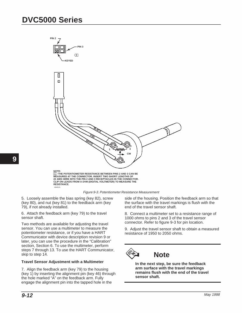
DVC5000 Series
May 19989-12
Figure 9-3. Potentiometer Resistance Measurement
NOTE: THE POTENTIOMETER RESISTANCE BETWEEN PINS 2 AND 3 CAN BEMEASURED AT THE CONNECTOR. INSERT TWO SHORT LENGTHS OF22 AWG WIRE INTO THE PIN 2 AND 3 RECEPTACLES IN THE CONNECTOR.CLIP ON LEADS FROM A DVM (DIGITAL VOLTMETER) TO MEASURE THERESISTANCE.
PIN 3
KEYED
PIN 2
CW
1 3
A6481/IL
1
1
5. Loosely assemble the bias spring (key 82), screw(key 80), and nut (key 81) to the feedback arm (key79), if not already installed.
6. Attach the feedback arm (key 79) to the travelsensor shaft.
Two methods are available for adjusting the travelsensor. You can use a multimeter to measure thepotentiometer resistance, or if you have a HARTCommunicator with device description revision 9 orlater, you can use the procedure in the “Calibration”section, Section 6. To use the multimeter, performsteps 7 through 13. To use the HART Communicator,skip to step 14.
Travel Sensor Adjustment with a Multimeter
7. Align the feedback arm (key 79) to the housing(key 1) by inserting the alignment pin (key 46) throughthe hole marked “A” on the feedback arm. Fullyengage the alignment pin into the tapped hole in the
side of the housing. Position the feedback arm so thatthe surface with the travel markings is flush with theend of the travel sensor shaft.
8. Connect a multimeter set to a resistance range of1000 ohms to pins 2 and 3 of the travel sensorconnector. Refer to figure 9-3 for pin location.
9. Adjust the travel sensor shaft to obtain a measuredresistance of 1950 to 2050 ohms.
NoteIn the next step, be sure the feedbackarm surface with the travel markingsremains flush with the end of the travelsensor shaft.
9

Maintenance
May 1998 9-13
10. While observing the resistance, tighten the screw(key 80) to secure the feedback arm to the travelsensor shaft. Be sure the resistance reading remainswithin the range listed in step 9. Paint the screw todiscourage tampering with the connection.
11. Disconnect the multimeter from the travel sensorconnector.
12. Reassemble the master module to the housing byperforming the Replacing the Master Moduleprocedure.
13. Travel sensor replacement is complete. Install thedigital valve controller on the actuator as described inthe “Installation” section, Section 2.
Travel Sensor Adjustment with the HARTCommunicator
The next two steps do not apply if you used amultimeter to adjust the travel sensor. Perform thesesteps only if you elected to adjust the travel sensorusing the HART Communicator.
14. Reassemble the master module to the housing byperforming the Replacing the Master Moduleprocedure.
15. Perform the appropriate Travel Sensor Adjustprocedure in the “Calibration” section, Section 6.
Type DVC5020 Digital Valve Controller Refer to figure 10-2 for key number locations.
1. Apply lubricant (key 63) to the bushing threads.
2. Insert the travel sensor assembly (key 77) into thehousing. Reach inside the housing and grasp the wiresattached to the connector.
3. Start threading the travel sensor assembly into thehousing, simultaneously guiding the wires to preventthem from winding up inside the housing. This willreduce potential damage to the soldered connections.
4. Tighten the travel sensor assembly against thehousing and tighten the set screw (key 58) to lock theassembly in place.
5. Loosely assemble the screw (key 80) and nut (key81) to the arm assembly (key 91), if not alreadyinstalled.
6. Attach the arm assembly (key 91) to the travelsensor assembly (key 77) shaft.
Two methods are available for adjusting the travelsensor. You can use a multimeter to measure thepotentiometer resistance, or if you have a HARTCommunicator with device description revision 9 orlater, you can use the procedure in the “Calibration”section, Section 6. To use the multimeter, perform
steps 7 through 17. To use the HART Communicator,skip to step 18.
Travel Sensor Adjustment with a Multimeter
7. Connect a multimeter set to a resistance range of1000 ohms to pins 2 and 3 of the travel sensorconnector. Refer to figure 9-3 for pin location.
8. Hold the arm assembly (key 91) in a fixed positionso that the arm is parallel to the housing back planeand pointing toward the terminal box. Position the armassembly so that the outer surface is flush with theend of the travel sensor shaft.
9. Adjust the travel sensor shaft to obtain a measuredresistance of 6250 to 6350 ohms.
NoteIn the next step, be sure the arm as-sembly outer surface remains flushwith the end of the travel sensor shaft.
10. While observing the resistance, tighten the screw(key 80) to secure the feedback arm to the travelsensor shaft. Be sure the resistance reading remainswithin the range listed in step 9. Paint the screw todiscourage tampering with the connection.
11. Disconnect the multimeter from the travel sensorconnector.
12. Apply lubricant (key 63 or equivalent) to the pinportion of the arm assembly (key 91).
13. Push the feedback arm into the housing, engagingthe pin of the arm assembly into the slot in thefeedback arm.
14. Install the washer (key 86) and E-ring (key 85)next to the inboard flange bearing (key 83).
15. Install the bias spring (key 93).
16. Reassemble the master module to the housing byperforming the Replacing the Master Moduleprocedure
17. Travel sensor replacement is complete. Install thedigital valve controller on the actuator as described inthe “Installation” section, Section 2.
Travel Sensor Adjustment with the HARTCommunicator
The next two steps do not apply if you used amultimeter to adjust the travel sensor. Perform thesesteps only if you elected to adjust the travel sensorusing the HART Communicator.
18. Reassemble the master module to the housing byperforming the Replacing the Master Moduleprocedure
9

DVC5000 Series
May 19989-14
19. Perform the appropriate Travel Sensor Adjustprocedure in the “Calibration” section, Section 6.
Type DVC5030 Digital Valve Controller Refer to figure 10-3 for key number locations.
1. Apply lubricant (key 63) to the bushing O-ring andthreads.
2. Screw the bushing into the housing until it is tight.
3. For units that mount on other than Fisheractuators, go to step 12.
4. For units that mount on Fisher actuators, attach thefeedback arm (key 79) to the travel sensor shaft.
Two methods are available for adjusting the travelsensor. You can use a multimeter to measure thepotentiometer resistance, or if you have a HARTCommunicator with device description revision 9 orlater, you can use the procedure in the “Calibration”section, Section 6. To use the multimeter, performsteps 5 through 11. To use the HART Communicator,skip to step 12.
Travel Sensor Adjustment with a Multimeter
5. Align the feedback arm (key 79) to the housing(key 1) by inserting the alignment pin (key 46) throughthe hole marked “A” on the feedback arm. Fullyengage the alignment pin into the tapped hole in theside of the housing. Position the feedback arm so thatthe outer surface is flush with the end of the travelsensor shaft.
6. Connect a multimeter set to a resistance range of1000 ohms to pins 2 and 3 of the travel sensorconnector. Refer to figure 9-3 for pin location.
7. Adjust the travel sensor shaft to obtain a measuredresistance of 1950 to 2050 ohms.
NoteIn the next step, be sure the feedbackarm outer surface remains flush withthe end of the travel sensor shaft.
8. While observing the resistance, tighten the screw(key 80) to secure the feedback arm to the travelsensor shaft. Be sure the resistance reading remainswithin the range listed in step 9. Paint the screw todiscourage tampering with the connection.
9. Disconnect the multimeter from the travel sensorconnector.
10. Reassemble the master module to the housing byperforming the Replacing the Master Moduleprocedure.
11. Travel sensor replacement is complete. Install thedigital valve controller on the actuator as described inthe “Installation” section, Section 2.
Travel Sensor Adjustment with the HARTCommunicator
The next two steps do not apply if you used amultimeter to adjust the travel sensor. Perform thesesteps only if you elected to adjust the travel sensorusing the HART Communicator.
12. Reassemble the master module to the housing byperforming the Replacing the Master Moduleprocedure.
13. Perform the appropriate Travel Sensor Adjustprocedure in the “Calibration” section, Section 6.
9

Parts
May 1998 10-1
10-10
Section 10 Parts
Parts Ordering 10-3. . . . . . . . . . . . . . . . . . . . . . . . . . . . . . . . . . . . . . . . . . . . . . . . . . . . . . . . . . .
Parts Kits 10-3. . . . . . . . . . . . . . . . . . . . . . . . . . . . . . . . . . . . . . . . . . . . . . . . . . . . . . . . . . . . . . . .
Parts List 10-3. . . . . . . . . . . . . . . . . . . . . . . . . . . . . . . . . . . . . . . . . . . . . . . . . . . . . . . . . . . . . . . .
Common Parts 10-3. . . . . . . . . . . . . . . . . . . . . . . . . . . . . . . . . . . . . . . . . . . . . . . . . . . . . . . . . . .
I/P Assembly 10-3. . . . . . . . . . . . . . . . . . . . . . . . . . . . . . . . . . . . . . . . . . . . . . . . . . . . . . . . . . . .
Module Base 10-3. . . . . . . . . . . . . . . . . . . . . . . . . . . . . . . . . . . . . . . . . . . . . . . . . . . . . . . . . . . .
Terminal Box 10-4. . . . . . . . . . . . . . . . . . . . . . . . . . . . . . . . . . . . . . . . . . . . . . . . . . . . . . . . . . . .
Relay 10-4. . . . . . . . . . . . . . . . . . . . . . . . . . . . . . . . . . . . . . . . . . . . . . . . . . . . . . . . . . . . . . . . . . . .
PWB Assembly 10-4. . . . . . . . . . . . . . . . . . . . . . . . . . . . . . . . . . . . . . . . . . . . . . . . . . . . . . . . . .
Pressure Gauges, Pipe Plugs, or Tire Valve Assemblies 10-4. . . . . . . . . . . . . . . . . . .
Feedback Parts 10-4. . . . . . . . . . . . . . . . . . . . . . . . . . . . . . . . . . . . . . . . . . . . . . . . . . . . . . . . . .
Mounting PartsDVC5010 Digital Valve Controller on:
513 & 513R, Size 20 10-4. . . . . . . . . . . . . . . . . . . . . . . . . . . . . . . . . . . . . . . . . . . . . . . . . . . . 513 & 513R, Size 32 10-5. . . . . . . . . . . . . . . . . . . . . . . . . . . . . . . . . . . . . . . . . . . . . . . . . . . . 657 & 667, Size 30–60 10-5. . . . . . . . . . . . . . . . . . . . . . . . . . . . . . . . . . . . . . . . . . . . . . . . . . 657 & 667, Size 70–100 10-5. . . . . . . . . . . . . . . . . . . . . . . . . . . . . . . . . . . . . . . . . . . . . . . . . 1250 & 1250R 10-5. . . . . . . . . . . . . . . . . . . . . . . . . . . . . . . . . . . . . . . . . . . . . . . . . . . . . . . . . . Gulde Model GA and P 10-5. . . . . . . . . . . . . . . . . . . . . . . . . . . . . . . . . . . . . . . . . . . . . . . . . .
DVC5020 Digital Valve Controller on:585 & 585R 10-5. . . . . . . . . . . . . . . . . . . . . . . . . . . . . . . . . . . . . . . . . . . . . . . . . . . . . . . . . . . . 1051, Size 30–60 10-5. . . . . . . . . . . . . . . . . . . . . . . . . . . . . . . . . . . . . . . . . . . . . . . . . . . . . . . 1051, Size 33 10-5. . . . . . . . . . . . . . . . . . . . . . . . . . . . . . . . . . . . . . . . . . . . . . . . . . . . . . . . . . 1052, Size 20 & 33 10-5. . . . . . . . . . . . . . . . . . . . . . . . . . . . . . . . . . . . . . . . . . . . . . . . . . . . . . 1052, Size 40–70 10-5. . . . . . . . . . . . . . . . . . . . . . . . . . . . . . . . . . . . . . . . . . . . . . . . . . . . . . .
DVC5030 Digital Valve Controller on Fisher Actuators:1051, Size 30–60 10-5. . . . . . . . . . . . . . . . . . . . . . . . . . . . . . . . . . . . . . . . . . . . . . . . . . . . . . . 1051, Size 33 10-5. . . . . . . . . . . . . . . . . . . . . . . . . . . . . . . . . . . . . . . . . . . . . . . . . . . . . . . . . . 1052, Size 20 10-6. . . . . . . . . . . . . . . . . . . . . . . . . . . . . . . . . . . . . . . . . . . . . . . . . . . . . . . . . . 1052, Size 33 10-5. . . . . . . . . . . . . . . . . . . . . . . . . . . . . . . . . . . . . . . . . . . . . . . . . . . . . . . . . . 1052, Size 40–70 10-5. . . . . . . . . . . . . . . . . . . . . . . . . . . . . . . . . . . . . . . . . . . . . . . . . . . . . . . 1066SR, Size 20, 27, & 75 10-6. . . . . . . . . . . . . . . . . . . . . . . . . . . . . . . . . . . . . . . . . . . . . . .
DVC5030 to Replace Positioners:Masoneilan Type 4600 10-6. . . . . . . . . . . . . . . . . . . . . . . . . . . . . . . . . . . . . . . . . . . . . . . . . . Neles-Jamesbury Type NP600, NE600, & NP723 10-6. . . . . . . . . . . . . . . . . . . . . . . . . . . PMV Model P1200, P1500, & P2000 10-6. . . . . . . . . . . . . . . . . . . . . . . . . . . . . . . . . . . . . .
Cam 10-6. . . . . . . . . . . . . . . . . . . . . . . . . . . . . . . . . . . . . . . . . . . . . . . . . . . . . . . . . . . . . . . . . . . . .
10

DVC5000 Series
May 199810-2
Filter Regulator Mounting Parts 10-6. . . . . . . . . . . . . . . . . . . . . . . . . . . . . . . . . . . . . . . . . . .
HART Filters 10-7. . . . . . . . . . . . . . . . . . . . . . . . . . . . . . . . . . . . . . . . . . . . . . . . . . . . . . . . . . . . .
10

Parts
May 1998 10-3
Parts Ordering Whenever corresponding with your Fisher Controlssales office or representative about this equipment,always mention the controller serial number. Whenordering replacement parts, refer to the 11-characterpart number of each required part as found in thefollowing parts list. Parts which do not show partnumbers are not orderable.
Parts Kits Conversion kit 6 listed below provides the partsrequired to convert a DVC5010 to a DVC5020.Conversion kit 7 provides the parts required to converta DVC5020 to a DVC5010.
Key Description Part Number1* Elastomer Spare Parts Kit 14B5072X0122* Relay Spare Parts Kit 14B5072X0223* Small Hardware Spare Parts Kit 14B5072X0326 Conversion Kit (DVC5010 to DVC5020)
Also see note below 14B5072X1027 Conversion Kit (DVC5020 to DVC5010) 14B5072X1129 Alignment Pin Kit (kit contains 15 alignment pins) 14B5072X092
Note
Conversion kit key 6 contains avent-away mounting bracket. Install a1/4-inch NPT socket head pipe plug inthe tapped hole in the side of themounting bracket if Type DVC5020digital valve controller is not forvent-away construction.
Parts ListParts which do not show part numbers are notorderable.
NoteParts with footnote numbers shown areavailable in parts kits. Also see footnoteinformation at the bottom of the page.
Key Description Part Number
Common Parts 1 Housing, aluminum
23 Cap Screw, hex socket, SST(3) (4 req’d) 1H3697X003233 Mach Screw, pan hd, SST(3) (3 req’d) 14B1930X01234* O-ring, nitrile(1) (2 req’d) 10A3802X01236* O-ring nitrile(1) 1H8762X001238 Cap Screw, hex socket, SST(3) (4 req’d) 1P71463899239* O-ring, nitrile(1) (2 req’d) 1D68750699240* O-ring, nitrile(1) 14B1935X01241 I/P Assembly (See I/P Assembly listing below)42* Gasket, nitrile(1) 34B0601X02243 Cover Assembly, plastic
For DVC5010, DVC5020, & DVC5030 34B0612X012For DVC5040 37B2518X012
48 Nameplate49 Drive Screw(3) (4 req’d)52 Vent, plastic(3)
Used w/DVC5010 and DVC5030 only 11B8279X01258 Set Screw, hex socket, SST(3) 14B1559X01261 Pipe Plug, hex socket, SST 1C3335X003262 Pipe Plug, hex hd, SST 1H5137X001263 Lubriplate Mag-1 Lubricant
(not furnished with the instrument)64 Zink-Plate No. 770 Anti-Seize Compound
(not furnished with the instrument)65 Dow Corning 111 Lubricant
(not furnished with the instrument)74 Mounting Bracket(6)
DVC5020 onlyStd 44B1219X022Vent-away 24B1376X012
75* O-Ring, nitrile(1,6)
DVC5020 Vent-away only 11A8741X052128 Pipe Plug, pl stl
DVC5020 Vent-away only 1E823128982211 Lubricant, Nyogel 760G
(not furnished with the instrument)
I/P Assembly I/P Converter w/shroud & boots 34B9710X022
41 I/P Converter169 Shroud210* Boot, nitrile (2 req’d) 12B4131X012
Module Base Master Module Assembly 14B5071X022The following parts are included in the mastermodule assembly.
2 Module Base Assembly 34B3169X01223 Cap Screw, (4 req’d)24 Relay Module(2) (See Relay listing below)33 Machine Screw, (3 req’d)38 Cap Screw, hex socket(3) (4 req’d)39 O-ring, (2 req’d)41 I/P Assembly w/shroud & boots
154 Retaining Ring (4 req’d)
10
* Recommended spare1. Available in the Elastomer Spare Parts Kit2. Available in the Relay Spare Parts Kit3. Available in the Small Hardware Spare Parts Kit6. Available in the DVC5010 to DVC5020 Conversion Kit

* Recommended spare1. Available in the Elastomer Spare Parts Kit2. Available in the Relay Spare Parts Kit3. Available in the Small Hardware Spare Parts Kit6. Available in the DVC5010 to DVC5020 Conversion Kit9. Available in the Alignment Pin Kit
DVC5000 Series
May 199810-4
Key Description Part Number
Terminal Box 4 Terminal Box Cap 34B0567X012
44 Wire Retainer, pl stl(3) (2 req’d) 14B3147X01258 Set Screw, hex socket, SST(3) 14B1559X01272 Cap Screw, hex socket, SST(3)
For DVC5010, DVC5020, DVC5030 1H3697X0032For DVC5040,Inch 1L545438992Metric 17B5168X012
164 Terminal Box AssemblyFor DVC5010, DVC5020, & DVC5030 34B8797X012For DVC5040 37B8798X012
Relay 24 Relay Module(2)
24L O-Ring(1, 2) (3 req’d)24M O-Ring(1, 2)
25 Mach Screw, pan hd(2) (4 req’d)26 Cap 34B0583X02231 Belleville Spring(2)
32 Washer(2)
152 O-ring, (4 req’d)
PWB Assembly 50* PWB Assembly
For instrument level AC 17B8801X062For instrument level HC 17B8801X072For instrument level SD 17B8801X082For instrument level AD 17B8801X092
Pressure Gauges, Pipe Plugs, or TireValve Assemblies 47* Pressure Gauge (2 req’d)
PSI/MPA/BAR Gauge ScalePlastic case, brass connectionTo 25 PSI, 170 kPa, 1.7 bar 11B4040X012To 50 PSI, 345 kPa, 3.4 bar 11B4040X022To 100 PSI, 690 kPa, 6.9 bar 11B4040X032
SST case, SST connectionTo 25 PSI, 170 kPa, 1.7 bar 11B4039X012To 50 PSI, 345 kPa, 3.4 bar 11B4039X022To 100 PSI, 690 kPa, 6.9 bar 11B4039X032
PSI/KG/CM2 Gauge ScalePlastic case, brass connectionTo 25 PSI, 1.8 kg/cm2 11B4040X042To 50 PSI, 3.5 kg/cm2 11B4040X052To 100 PSI, 7.0 kg/cm2 11B4040X062
66 Pipe Plug, hex hd (2 req’d)Plated steel 1D829328982SST 1D8293X0012
67 Tire Valve Assembly, pl stl (2 req’d) 1N908899012
Feedback Parts 46 Alignment Pin(9)
For DVC5010, DVC5030 & DVC5040 only 14B0656X02277 Potentiometer and Bushing Assy
For DVC5010 & DVC5020 14B5070X052For DVC5030 17B4030X012For DVC5040 17B4031X012
Key Description Part Number
78 Bias Spring, SST(3)
For DVC5010, DVC5030, & DVC5040 24B0654X03279 Feedback Arm, SST
DVC5010For 513, 513R, 529, 585C, 585CR, 656,657/30-100, and 667/30-100 37B5270X012
For all sizes 1250 and 1250R 37B5270X022DVC5040For 9000/all sizes 34B1929X012
DVC5030For all sizes 1051, 1052, and 1066SR 34B2179X012
80 Cap Screw, hex socket, SST(3) 14B6978X01281 Square Nut, SST(3) 16A6711X03282 Bias Spring, SST(3) DVC5020 only 24B1532X01283 Flange Bearing, Rulon(6) DVC5020 only (2 req’d) 13A1592X01284 Feedback Arm Assy, SST(6)
DVC5020 onlyFor 471, 585, 585R 1051/30-60and 1052/40-70 14B1557X022
For 1051/33 and 1052/20, 33 14B1377X02285 E-ring, pl stl(3) DVC5020 only (2 req’d) 1E45532898286 Plain Washer, pl stl(6) DVC5020 only (2 req’d) 1A49882898287 Follower Post, SST(6) DVC5020 only 13A1656X01288 Roller, SST/PTFE(6) DVC5020 only 13A1657X01289 Spring Lock Washer, pl stl(6) DVC5020 only 1H26722898290 Hex Nut, pl stl(6) DVC5020 only 1A83962898291 Arm Assy, SST(6) DVC5020 only 14B0659X02292 Cap Screw, hex socket(6) DVC5020 only (4 req’d) 1L7325X001293 Torsion Spring, Feedback Arm(6) DVC5020 only 14B1426X012
104 Cap Screw, hex hd (4 req’d)For DVC5010 only 1A3917X0052Not for mounting on 1250 and 1250R actuators, seemounting parts below.
107 Mounting BracketFor DVC5010 only 44B0655X022Not for mounting on 1250 and 1250R actuators, seemounting parts below.
121 Thread Lock, Loctite 242(not furnished with instrument)
160 Sealant, Torque Seal(not furnished with instrument)
163 Plain Washer, SST 14B6976X012
Mounting Parts
Type DVC5010 Digital Valve Controller For Types 513 and 513R, size 20 actuators
102 Shield, polyester 34B1428X012103 Mach Screw, pan hd, pl stl(3) (2 req’d) 11A6514X012106 Adjustment Arm, aluminum/SST 24B0651X032108 Connector Arm, pl stl 24B8879X012109 Mach Screw, hex hd, pl stl 13A1617X012110 Lock Washer, ext, pl stl 14B0698X012118 Spacer, pl stl (2 req’d) 1N254224102119 Spacer, SST (2 req’d) 1L759024092120 Cap Screw, hex hd, pl stl (2 req’d) 1C870224052122 Plain Washer, pl stl (2 req’d) 1B865928982126 Plain Washer, pl stl 14B4140X012
10

Parts
May 1998 10-5
Key Description Part Number155 Cap Screw, hex hd, pl stl (2 req’d) 1B787724052
For Types 513 and 513R, size 32 actuators102 Shield, polyester 34B1428X012103 Mach Screw, pan hd, pl stl(3) (2 req’d) 11A6514X012106 Adjustment Arm, aluminum/SST 24B0651X032108 Connector Arm, pl stl 24B0652X012109 Mach Screw, hex hd, pl stl 13A1617X012110 Lock Washer, ext, pl stl 14B0698X012118 Spacer, pl stl (2 req’d) 1N254224102119 Spacer, pl stl (2 req’d) 1L759024092120 Cap Screw, hex hd, pl stl (2 req’d) 1C870224052122 Plain Washer, pl stl (2 req’d) 1B865928982126 Plain Washer, pl stl 14B4140X012155 Cap Screw, hex hd, pl stl (2 req’d) 1B787724052
For Types 657 & 667, size 30-60 actuators102 Shield, polyester 34B1428X012103 Mach Screw, pan hd, SST(3) (2 req’d) 11A6514X022105 Screw, hex flg, SST
W/o side-mtd h’wheel (2 req’d) 14B1379X032W/side-mtd h’wheel (none req’d) – – –
106 Adjustment Arm, aluminum/SST 24B0651X032108 Connector Arm, stl
W/o side-mtd h’wheel 24B0652X012W/side-mtd h’wheel 32B3526X012
109 Mach Screw, hex hd, SST 13A1617X022110 Lock Washer, ext, pl stl 14B0698X012126 Plain Washer, SST 14B4140X022148 Spacer, pl stl
W/o side-mtd h’wheel (none req’d) – – –W/side-mtd h’wheel (2 req’d)For size 34, 40 1J830724092For size 45–60 1F906724092
155 Cap screw, hex hd, SSTW/o side-mtd h’wheel (none req’d) – – –W/side-mtd h’wheel (2 req’d)For size 34, 40 1A352538992For size 45–60 1B7877X0012
156 Washer, SSTW/o side-mtd h’wheel (2 req’d) 1B8659X0012W/side-mtd h’wheel (none req’d) – – –
For Types 657 & 667, size 70-100 actuators97 Feedback Arm Ext, SST 42B9010X01298 Mach Screw, hex hd, SST 12B2922X01299 Mach Screw, flat hd, SST 14B6701X012
100 Hex Nut, SST (2 req’d) 1A3303X0012101 Spacer, SST 14B1554X012102 Shield, SST 44B1429X012103 Mach Screw, pan hd, SST(3) (2 req’d) 1N10183X022105 Screw, hex flg, SST (2 req’d) 14B1379X032106 Adjustment Arm, aluminum/SST 24B0651X032108 Connector Arm, stl
W/o side-mtd h’wheel 22B9008X012W/side-mtd h’wheel 23B9247X012
109 Mach Screw, hex hd, SST 13A1617X022110 Lock Washer, ext, pl stl 14B0698X012126 Plain Washer, SST 14B4140X022156 Washer, SST (2 req’d)
For 657 size 70 14B5349X022For 657 size 80–100 1K8995X0022
162 Lock Washer, split, SST 61000580X12For Types 1250 & 1250R actuators, all sizesand Gulde Model GA and P actuators
102 Shield, polyester 34B1428X012103 Mach Screw, pan hd, pl stl(3) (2 req’d) 11A6514X012104 Cap Screw, hex hd, pl stl (4 req’d) 1A3917X0052106 Adjustment Arm, aluminum/SST 24B0651X032
Key Description Part Number107 Mounting Bracket, pl stl 44B0224X012108 Connector Arm, pl stl 34B0223X012109 Mach Screw, hex hd, pl stl 13A1617X012110 Lock Washer, ext, pl stl 14B0698X012111 Brace 44B0225X012112 Cap Screw, hex hd, pl stl (2 req’d) 19A4833X012113 Cap Screw, hex hd, pl stl (2 req’d) 10B6605X012114 U-Bolt, pl stl (4 req’d) 14B0226X012115 Hex Nut, pl stl (10 req’d) 19A4788X012123 Plain Washer, pl stl (2 req’d) 10B6633X012124 Plain Washer, pl stl (2 req’d) 10B6609X012125 Cap Screw, hex hd, pl stl 19A4775X012126 Plain Washer, pl stl 14B4140X012127 Lock Washer, pl stl (8 req’d) 11Y8560R082
Type DVC5020 Digital Valve Controller For Type 585 and 585R Actuators
84 Feedback Arm Ass’y, SST 17B3156X01294 Cam, SST 27B3157X01298 Machine Screw, hex hd, SST (2 req’d) 13A1618X022
100 Hex Nut, SST (2 req’d) 1A6622X0012116 Cap Screw, hex socket, pl stl (8 req’d) 1P7146X0022117 Mounting Adaptor 44B1220X012162 Lock Washer, SST (2 re’d) 1A3291X0012170 Reversing Relay 15A8804X352171 Pipe Bushing, hex (2 req’d)
Plated steel 1B6149X0012SST 1B6149X0032
172 Pipe TeePlated steel 1C597547362SST 1P506938982
173 Cap Screw, hex hd, pl stl (2 req’d) 1C631224052174 Pipe Nipple
Plated steel 1C678926232SST 1P5068X0012
175 Pipe NipplePlated steel 1A385026012SST 1A3580X0012
176 Pipe Bushing, hexPlated steel 1E253726232SST 1E2537K0012
203 Follower Arm Extension, SST 17B3158X012For Type 1051, size 30-60 and Type 1052,size 40-70 actuators
116 Cap Screw, hex socket, SST (4 req’d) 1P714638992For Type 1051, size 33 and Type 1052size 20 & 33 actuators
116 Cap Screw, hex socket, SST (8 req’d) 1P714638992117 Mounting Adaptor 44B1220X012
Type DVC5030 Digital Valve Controller For Types 1051, size 30-60 and Type 1052,size 40-70 actuators
104 Cap Screw, hex head, SST (4 req’d) 1B2905X0012107 Mounting Bracket Ass’y, stl/SST 34B9501X012140 Washer, pl stl (4 req’d)
For 1051 size 30–40 & 1052 size 40 1H723125072For 1051 size 60 & 1052 size 60–70 1A518925072
142 Travel Indicator Scale, SST 24B2183X012144 Travel Indicator Ass’y, SST 24B2178X012145 Machine Screw, pan hd, SST (2 req’d) 59061180X12198 Plain Washer, SST (2 req’d) 61000350X12204 Hex Nut, SST (2 req’d) 1A3303X0012
For Type 1051 and 1052, size 33 actuators104 Cap Screw, hex hd, SST (4 req’d) 1B2905X0012107 Mounting Bracket Ass’y 34B9503X012
10
3. Available in the Small Hardware Spare Parts Kit.

* Recommended spare
DVC5000 Series
May 199810-6
Key Description Part Number140 Washer, pl stl (4 req’d) 1B865928982141 Spacer, pl stl 17B1702X012142 Travel Indicator Scale, SST 24B2183X012144 Travel Indicator Ass’y, SST 24B2178X012145 Machine Screw, pan hd, SST (2 req’d) 13B9244X012191 Cap Screw, hex hd, pl stl (4 req”d) 1A381624052198 Plain Washer, SST (2 req’d) 61000350X12199 Washer, pl stl (2 req’d) 1K261028992204 Hex Nut, SST (2 req’d) 1A3303X0012
For Type 1052, size 20 actuators104 Cap Screw, hex hd, SST (4 req’d) 1B2905X0012107 Mounting Bracket Ass’y stl/SST 34B9502X012141 Spacer, pl stl 17B1701X012142 Travel Indicator Scale, SST 24B2183X012144 Travel Indicator Ass’y, SST 24B2178X012145 Machine Screw, pan hd, SST (2 req’d) 59061300X12191 Cap Screw, hex hd, pl stl (4 req”d) 1A353124052198 Plain Washer, SST (2 req’d) 61000350X12204 Hex Nut, SST (2 req’d) 1A3303X0012
For Type 1066SR actuators104 Cap Screw, hex hd, SST (4 req’d) 1B2905X0012107 Mounting Bracket Ass’y 34B9503X012140 Washer, pl stl (4 req’d)
For size 20 1B865928982For size 27 1H723125072For size 75 1A518925072
141 Spacer, pl stlFor sizes 20 & 27 17B1703X012For size 75 17B1710X012
142 Travel Indicator Scale, SST 24B2183X012144 Travel Indicator Ass’y, SST 24B2178X012145 Machine Screw, pan hd, SST (2 req’d)
For sizes 20 & 27 14B2026X012For size 75 14B2027X012
198 Plain Washer, SST (2 req’d) 61000350X12199 Washer, pl stl
For sizes 20 & 27 (2 req’d) 1K261028992For size 75 (none req’d) – – –
204 Hex Nut, SST (2 req’d) 1A3303X0012
Type DVC5030 Digital Valve Controller onOther Actuators
To replace Masoneilan positioners177 Emulator, steel 37B2821X012178 Positioner Plate, steel 37B2819X012179 Shaft Connector, pl stl 27B2804X012180 Coupler, SST 17B2810X012181 Connector Cap Ass’y, stl/SST 17B3929X012182 Spacer, pl stl (3 req’d) 17B2806X012184 Cap Screw, SST (3 req’d) 17B2807X012185 Cap Screw, SST 17B2978X012186 Cap Screw, SST (2 req’d) 1P714638992187 Cap Screw, SST (4 req’d) 1A391738992188 Machine Screw, SST (2 req’d) 17B2808X012
To replace Neles-Jamesbury positioners177 Emulator, steel 37B2811X012178 Positioner Plate, steel 37B2817X012180 Coupler, SST 17B2810X012182 Spacer, pl stl (3 req’d) 17B2814X012184 Cap Screw, SST (3 req’d) 17B2815X012187 Cap Screw, SST (4 req’d) 1A391738992189 Cap Screw, SST (3 req’d) 1C2752X0042190 Tie Bar Ass’y, SST 27B2816X012
Key Description Part Number205 Screw, self-tapping, pl stl 12B6373X012206 Pointer, nylon 22B6372X012207 Scale, plastic
For clockwise rotation opens valve 27B3853X012For clockwise rotation closes valve 27B3854X012
To replace PMV positioners177 Emulator, steel 37B2821X012178 Positioner Plate, steel 37B2819X012180 Coupler, SST 17B2810X012182 Spacer, pl stl (3 req’d) 1R793424492184 Cap Screw, SST (3 req’d) 17B2822X012187 Cap Screw, SST (4 req’d) 1A391738992189 Cap Screw, SST (2 req’d) 1C2752X0042205 Screw, self-tapping, pl stl 12B6373X012206 Pointer, nylon 22B6371X012207 Scale, plastic
For clockwise rotation opens valve 27B3906X012For clockwise rotation closes valve 27B3907X012
Cam For DVC5020 onlyFor Type 1051, size 30-60 and 1052,size 40-70 actuators
94 Cam, SST 33A1613X02295 Mach Screw, hex hd, SST (2 req’d) 13A1618X022
For Type 1052, size 20 actuators94 Cam, SST 36A4653X02295 Mach Screw, hex hd, SST (2 req’d) 13A1617X022
For Type 1051 and 1052, size 33 actuators94 Cam, SST 30B1529X02295 Mach Screw, hex hd, SST (2 req’d) 13A1617X022
Filter Regulator Mounting Parts For use only when filter regulator isspecified.For Integral Mounting
59 Cap Screw, hex hd, SST (2 req’d) 1C3988X002260* O-Ring, nitrile 1E59140699261 Pipe Plug, hex socket, SST 1C3335X0012
For Casing Mounting61 Pipe Plug, hex socket, SST 1C3335X001269 Hex Nut, pl stl (2 req’d) 1A35272412270 Cap Screw, hex hd, pl stl (2 req’d) 1C19702405271 Mounting Bracket, pl stl 1F401225072
For Yoke Mounting59 Cap Screw, hex hd, SST (2 req’d) 1C3988X002261 Pipe Plug, hex socket, SST 1C3335X0012
For Wall Mounting161 Pipe Nipple, galv stl 1C678926232
For Universal Mounting59 Cap Screw, hex hd, SST (2 req’d) 1C3988X002260* O-Ring, nitrile 1E59140699261 Pipe Plug, hex socket, SST 1C3335X001269 Hex Nut, pl stl (2 req’d) 1A35272412270 Cap Screw, hex hd, pl stl (2 req’d) 1C19702405271 Mounting Bracket 1F401225072161 Pipe Nipple, galv stl 1C678926232
10

Parts
May 1998 10-7
Figure 10-1. Type DVC5010 Digital Valve Controller Assembly
APPLY LUB, SEALANT43B8444-J / DOCSHT 1 OF 2SHT 2 OF 2
SECTION C-C
SECTION B-B
SECTION A-A
A
B
C
CB
A
Key Description Part Number
HART Filters HF100, HART Filter 14B1934X012HF210, cage clamp, normal polarity 17B1181X012HF210, cage clamp, reverse polarity 17B1182X012
Key Description Part NumberHF220, screw terminal, normal polarity 17B1184X012HF220, screw terminal, reverse polarity 17B1185X012HF230, tiered terminal 17B1186X012HF240, DIN rail mount 17B1187X012HF240, DIN rail Mount,pass through (no filter) 17B1188X012
10

DVC5000 Series
May 199810-8
Figure 10-2. Type DVC5020 Digital Valve Controller Assembly43B8446-J / DOCSHT 2 OF 3
APPLY LUB, SEALANT
SECTION C-C
SECTION B-BSECTION A-A
A
B
C
C
B
A
10

Parts
May 1998 10-9
Figure 10-3. Type DVC5030 Digital Valve Controller Assembly
SECTION B-B
SECTION A-AA
B
B
A
APPLY LUB, SEALANT44B3158-D / DOCSHT 1 OF 2SHT 2 OF 2
10

DVC5000 Series
May 199810-10
Figure 10-4. Type DVC5040 Digital Valve Controller Assembly
SECTION B-B
SECTION A-A
APPLY LUB, SEALANT
A
A
47B0907-C / DOCSHT 2 OF 2
Figure 10-5. Typical DVC5000 Series Digital Valve Controller with Tire Valves and Pipe Plugs
DVC5000 SERIES WITH TIRE VALVES DVC5000 SERIES WITH PIPE PLUGS APPLY LUB, SEALANT
47B8444-J / DOCSHT 2 OF 2
10

Parts
May 1998 10-11
Figure 10-6. Type HF210 HART Filter Mounted on ControlSystem Cage–Clamp Style Termination
TYPE HF210HART FILTER HART
COMMUNICATIONWIRE PAIR
FIELDINSTRUMENTCONNECTION
PLUG TERMINATINGHART COMMUNICATIONWIRE PAIR
W6599 / IL
Figure 10-7. Type HF220 HART Filter Mounted on ControlSystem Single–Row–Screw–Terminal Style Termination
HARTCOMMUNICATIONWIRE PAIR
FIELDINSTRUMENTCONNECTION
TYPE HF220HART FILTER
PLUG TERMINATINGHART COMMUNICATIONWIRE PAIR
W6600 / IL
Figure 10-8. Type HF230 HART Filter Mounted on ControlSystem Two–Tier–Screw–Terminal (Staggered) Termination
HARTCOMMUNICATIONWIRE PAIR
TYPE HF230HART FILTER
PLUG TERMINATINGHART COMMUNICATIONWIRE PAIR
FIELDINSTRUMENTCONNECTIONW6601 / IL
Figure 10-9. Type HF240 HART Filter (DIN Rail Mount)
CONTROL SYSTEM CONNECTION
HART COMMUNICATIONCONNECTION
FIELD INSTRUMENTCONNECTION
W6493*/ IL 10

DVC5000 Series
May 199810-12
10

Loop Schematics
May 1998 11-1
11-11
Section 11 Loop Schematics This section includes loop schematics required forwiring of intrinsically safe installations. If you have anyquestions, contact your Fisher Controls sales
representative or sales office.
CSA Schematics
CSA Schematic Sheet 124B8244-C SHT 2 DOC
11

DVC5000 Series
May 199811-2
CSA Schematics (continued)
CSA Schematic Sheet 2
CSA Schematic Sheet 3
24B8244-A SHT 3 / DOC
24B8244-A SHT 4 / DOC
11

Loop Schematics
May 1998 11-3
CSA Schematics (continued)
CSA Schematic Sheet 424B8244-B SHT 5 / DOC
11

DVC5000 Series
May 199811-4
FM Schematics
FM Schematic Sheet 1
FM Schematic Sheet 2
24B8243-B SHT 1 OF 2 / DOC
24B8243-B SHT 2 OF 2 / DOC
11
Glossary
May 1998 Glossary-1
L-L-
GlossaryAlert Point
An adjustable value that, when exceeded,activates an alert.
AlgorithmA set of logical steps to solve a problem oraccomplish a task. A computer program containsone or more algorithms.
AlphanumericConsisting of letters and numbers.
Analog Input UnitsUnits in which the analog input is displayed andmaintained in the instrument.
ANSI (acronym)The acronym ANSI stands for the AmericanNational Standards Institute
ANSI ClassValve pressure/temperature rating.
Auxiliary Input AlertChecks the status of the auxiliary input; a discreteinput. When enabled, the Auxiliary Input Alert isactive when the auxiliary input terminals areclosed (shorted).
Auxiliary Terminal (Indicator)Indicates whether auxiliary wiring terminals areopen or closed (such as by an external switchcontact).
Bench SetPressure, supplied to an actuator, required todrive the actuator through rated valve travel.Expressed in pounds per square inch.
ByteA unit of binary digits (bits). Usually a byteconsists of eight bits.
Calibration LocationWhere the instrument was last calibrated; eitherin the factory or in the field.
ConfigurationStored instructions and operating parameters fora FIELDVUE Instrument.
Control LoopAn arrangement of physical and electroniccomponents for process control. The electroniccomponents of the loop continuously measureone or more aspects of the process, then alterthose aspects as necessary to achieve a desiredprocess condition. A simple control loopmeasures only one variable. More sophisticatedcontrol loops measure many variables andmaintain specified relationships among thosevariables.
Control ModeDefines where the instrument reads its set point.The following control modes are available for aFIELDVUE Instrument:RSP (Remote Set Point) The instrument receivesits travel set point over the 4–20 mA loop. COMand SUPV work the same.COM ComputerSUPV SupervisoryAUTO (Automatic) The instrument receives itsset point digitally, via the HART communicationslink. MAN (Manual)DDC (Direct Digital Control) The instrumentreceives its set point digitally, via the HARTcommunications link.
Control Mode, RestartDetermines the instrument control mode after arestart. See Control Mode for the availablerestart control modes.
12GlossaryGlossary

DVC5000 Series
May 1998Glossary-2
ControllerA device that operates automatically to regulate acontrolled variable.
Crossover PointThe mid-point of the stroking range of asliding-stem actuator. A visual indication of thecrossover point is found when the slot in theinstrument feedback arm forms a 90-degreeangle with the valve stem.
Current-to-Pressure (I/P) ConverterAn electronic component or device that convertsa milliamp signal to a proportional pneumaticpressure output signal.
Cycle CounterThe capability of a FIELDVUE instrument torecord the number of times the travel changesdirection. The change in direction must occurafter the deadband has been exceeded before itcan be counted as a cycle.
Cycle Counter AlertChecks the difference between the Cycle Counterand the Cycle Counter Alert Point. Cycle CounterAlert is active when the cycle counter valueexceeds the Cycle Counter Alert Point. It clearsafter you reset the Cycle Counter to a value lessthan the alert point.
Cycle Counter Alert PointAn adjustable value which, when exceeded,activates the Cycle Counter Alert. Valid entriesare 0 to 4 billion cycles.
Cycle Counter DeadbandRegion around the travel reference point, inpercent of ranged travel, established at the lastincrement of the Cycle Counter. The deadbandmust be exceeded before a change in travel canbe counted as a cycle. Valid entries are 0% to100%. Typical value is between 2% and 5%.
DeviationUsually, the difference between set point andprocess variable. More generally, any departurefrom a desired or expected value or pattern.
Device IDUnique identifier embedded in the instrument atthe factory.
Drive SignalThe signal to the I/P converter from the printedwiring board. It is the percentage of the totalmicroprocessor effort needed to drive the valvefully open. In most applications, drive signalranges from 55% to 75% in the active travelrange. The drive signal may be higher or lower atthe travel end points.
Drive Signal AlertChecks the drive signal and calibrated travel. Ifone of the following conditions exists for morethan 20 seconds, the Drive Signal Alert is active.If none of the conditions exist, the alert is cleared.If Zero Control Signal = Closed
The alert is active when:
drive signal <10% and calibrated travel >3%
drive signal >90% and calibrated travel <97%
If Zero Control Signal = Open
The alert is active when:
drive signal <10% and calibrated travel <97%
drive signal >90% and calibrated travel >3%
Equal PercentageA valve flow characteristic where equalincrements of valve stem travel produce equalpercentage changes in existing flow. One of theinput characteristics available for a FIELDVUEInstrument. See also, Linear and Quick Opening.
Factory Instrument Serial NumberThe serial number assigned to the printed wiringboard by the factory that cannot be changed.
Feedback ArmThe mechanical connection between the valvestem linkage and the FIELDVUE Instrumenttravel sensor.
Feedback CharacteristicIdentifies to the FIELDVUE Instrument if thefeedback signal is coming from a rotary orsliding-stem valve.
12Glossary

Glossary
May 1998 Glossary-3
Feedback SignalIndicates to the instrument the actual position ofthe valve. The travel sensor provides thefeedback signal to the instrument printed wiringboard assembly. A mechanical linkage connectsthe travel sensor to the valve stem or shaft.
Field Instrument Serial NumberThe serial number assigned to the printed wiringboard by the factory but can be changed duringsetup. The field instrument serial number shouldmatch the serial number on the instrumentnameplate.
Firmware RevisionThe revision number of the instrument firmware.Firmware is a program that is entered into theinstrument at time of manufacture and cannot bechanged by the user.
Free TimePercent of time that the microprocessor is idle. Atypical value is 25%. The actual value dependson the number of functions in the instrument thatare enabled and on the amount of communicationcurrently in progress.
Full Ranged TravelCurrent, in mA, that corresponds with the pointwhere ranged travel is maximum, i.e., limited bythe mechanical travel stops.
GainThe ratio of output change to input change.
Hardware RevisionRevision number of the Fisher Controlsinstrument hardware. The physical componentsof the instrument are defined as the hardware.
HART (acronym)The acronym HART stands for HighwayAddressable Remote Transducer.
HART TagAn eight-character name that identifies thephysical instrument.
HART Universal RevisionRevision number of the HART UniversalCommands which are the communicationsprotocol for the instrument.
Input CharacteristicThe relationship between the ranged travel andranged input. Possible values include: linear,equal percentage, and quick opening.
Input CurrentThe current signal from the control system thatserves as the analog input to the instrument. Seealso Input Signal.
Input Filter TimeThe time constant, in seconds, for the first-orderinput filter.
Input RangeThe analog input signal range that corresponds tothe travel range.
Input SignalThe current signal from the control system. Theinput signal can be displayed in milliamperes or inpercent of ranged input.
Instrument LevelDetermines the functions available for theinstrument. See table 7-1, page 7-3.
Instrument ModeDetermines if the instrument responds to itsanalog input signal. There are two instrumentmodes:In Service: For a fully functioning instrument, theinstrument output changes in response to analoginput changes. Typically changes to setup orcalibration cannot be made when the instrumentmode is In Service.Out of Service: The instrument output does notchange in response to analog input changeswhen the instrument mode is Out of Service.Some setup parameters can be changed onlywhen the instrument mode is Out of Service.
12Glossary

DVC5000 Series
May 1998Glossary-4
Instrument ProtectionDetermines if commands from a HART devicecan calibrate and/or configure certain parametersin the instrument. There are three types ofinstrument protection:Configuration and Calibration: Prohibitschanging protected setup parameters; prohibitscalibration.Configuration: Prohibits changing protectedsetup parameters; permits calibration.None : Permits both configuration and calibration.The instrument is ”unprotected.”
Interface RevisionRevision number of the interface software thatpermits communication between the HARTCommunicator and the instrument.
Invert FeedbackEstablishes feedback orientation. While viewingthe end of the travel sensor shaft, if increasing airpressure to the actuator causes the shaft torotate clockwise, invert feedback is YES. Ifincreasing air pressure causes the shaft to rotatecounterclockwise, invert feedback is NO.
Leak ClassDefines the allowable leakage by a valve when itis closed. Leak class numbers are listed in twostandards: ANSI/FCI 70-2-1991 and IEC 534-4(1986).
LinearA valve flow characteristic where changes in flowrate are directly proportional to changes in valvestem travel. One of the input characteristicsavailable for a FIELDVUE Instrument. See also,Equal Percentage and Quick Opening.
Linearity, dynamicLinearity (independent) is the maximum deviationfrom a straight line best fit to the opening andclosing curves and a line representing theaverage value of those curves.
MemoryA type of semiconductor used for storingprograms or data. FIELDVUE instruments usethree types of memory: Random Access Memory(RAM), Read Only Memory (ROM), andNon-Volatile Memory (NVM). See also theselistings in this glossary.
MenuA list of programs, commands, or other activitiesthat you select by using the arrow keys tohighlight the item then pressing ENTER, or byentering the numeric value of the menu item.
Minimum Closing TimeMinimum time, in seconds, for the travel todecrease through the entire ranged travel. Thisrate is applied to any travel decrease. Validentries are 0 to 400 seconds. To deactivate, entera value of 0 seconds.
Minimum Opening TimeMinimum time, in seconds, for the travel toincrease through the entire ranged travel. Thisrate is applied to any travel increase. Because offriction, actual valve travel may not respond inexactly the same time frame. Valid entries are 0to 400 seconds. To deactivate, enter a value of 0seconds.
Non-Volatile Memory (NVM)A type of semiconductor memory that retains itscontents even though power is disconnected.NVM contents can be changed duringconfiguration unlike ROM which can be changedonly at time of instrument manufacture. NVMstores configuration restart data.
ParallelSimultaneous: said of data transmission on two ormore channels at the same time.
Polling AddressAddress of the instrument. If the digital valvecontroller is used in a point-to-point configuration,set the polling address to 0. If it is used in amultidrop configuration, or split range application,set the polling address to a value from 0 to 15.
12Glossary

Glossary
May 1998 Glossary-5
Pressure SensorA FIELDVUE instrument internal device thatsenses the output pressure from the pneumaticrelay.
Primary MasterMasters are communicating devices. A primarymaster is a communicating device permanentlywired to a field instrument. Typically, a computerrunning ValveLink VL2000 Series software is theprimary master.
In contrast, a secondary master is not oftenpermanently wired to a field instrument. TheModel 275 HART Communicator or a computerrunning ValveLink software communicatingthrough a HART modem could be considered asecondary master.
Note: If one type of master takes an instrumentOut Of Service, the same type must put it InService. For example, if a device set up as aprimary master takes an instrument Out OfService, a device set up as a primary mastermust be used to place the instrument In Service.
Quick OpeningA valve flow characteristic where most of thechange in flow rate takes place for small amountsof stem travel from the closed position. The flowcharacteristic curve is basically linear through thefirst 40 percent of stem travel. One of the inputcharacteristics available for a FIELDVUEInstrument. See also, Equal Percentage andLinear.
Random Access Memory (RAM)A type of semiconductor memory that is normallyused by the microprocessor during normaloperation that permits rapid retrieval and storageof programs and data. See also Read OnlyMemory (ROM) and Non-Volatile Memory (NVM).
RateAmount of change in output proportional to therate of change in input.
Read-Only Memory (ROM)A memory in which information is stored at thetime of instrument manufacture. You canexamine but not change ROM contents.
Seat LoadForce exerted on the valve seat, typicallyexpressed in pounds force per lineal inch of portcircumference. Seat load is determined by shutoffrequirements.
SoftwareMicroprocessor or computer programs androutines that reside in alterable memory (usuallyRAM), as opposed to firmware, which consists ofprograms and routines that are programmed intomemory (usually ROM) when the instrument ismanufactured. Software can be manipulatedduring normal operation, firmware cannot.
Stroking TimeThe time, in seconds, required to move the valvefrom its fully open position to fully closed, or viceversa.
Temperature SensorA device within the FIELDVUE instrument thatmeasures the instrument’s internal temperature.
TravelMovement of the valve stem or shaft whichchanges the amount the valve is open or closed.
Travel AccumulatorThe capability of a FIELDVUE instrument torecord total change in travel. The value of theTravel Accumulator increments when themagnitude of the change exceeds the TravelAccumulator Deadband. To reset the TravelAccumulator, set it to zero.
Travel Accumulator AlertChecks the difference between the TravelAccumulator value and the Travel AccumulatorAlert Point. The Travel Accumulator Alert is activewhen the Travel Accumulator value exceeds theTravel Accumulator Alert Point. It clears after youreset the Travel Accumulator to a value less thanthe alert point.
Travel Accumulator Alert PointAn adjustable value which, when exceeded,activates the Travel Accumulator Alert. Validentries are 0% to 4 billion %.
12Glossary

DVC5000 Series
May 1998Glossary-6
Travel Accumulator DeadbandRegion around the travel reference pointestablished at the last increment of theaccumulator. This region must be exceededbefore a change in travel can be accumulated.Valid entries are 0% to 100%.
Travel AlertChecks the ranged travel against the Travel AlertHigh and Low Points. The travel Alert is active ifeither the high or low point is exceeded. Once ahigh or low point is exceeded, the ranged travelmust clear that point by the Travel AlertDeadband before the alert clears. Two travelalerts are available: Travel Alert 1 and TravelAlert 2.
Travel Alert DeadbandTravel, in percent of ranged travel, required toclear a travel alert, once it is active. Valid entriesare –25% to 125%.
Travel Alert High PointValue of the travel, in percent of ranged travel,which, when exceeded, sets the Travel Alert Highalert. Valid entries are –25% to 125%.
Travel Alert Low PointValue of the travel, in percent of ranged travel,which, when exceeded, sets the Travel Alert Lowalert. Valid entries are –25% to 125%.
Travel CutoffDefines the cutoff point for the travel, in percentof ranged travel. There are two travel cutoffs:high and low. Once travel exceeds the cutoff, thedrive signal is set to either maximum or minimum,depending on the Zero Control Signal and if thecutoff is high or low. Minimum opening time orminimum closing time are not in effect while thetravel is beyond the cutoff. Use the travel cutoff toobtain the desired seat load or to be sure thevalve is fully open.
Travel DeviationThe difference between the analog input signal (inpercent of ranged input), the “target” travel, andthe actual “ranged” travel.
Travel Deviation AlertChecks the difference between the target and theranged travel. If the difference exceeds the TravelDeviation Alert Point for more than the TravelDeviation Time, the Travel Deviation Alert isactive. It remains active until the difference is lessthan the Travel Deviation Alert Point.
Travel Deviation Alert PointAn adjustable value for the target travel and theranged travel difference, expressed in percent,When this value is exceeded by the traveldeviation for more than the Travel DeviationTime, the Travel Deviation Alert is active. Validentries are 0% to 100%. Typically this is set to5%.
Travel Deviation TimeThe time, in seconds. that the travel deviationmust exceed the Travel Deviation Alert Pointbefore the alert is active. Valid entries are 1 to 60seconds.
Travel LimitA setup parameter that defines the maximumallowable travel (in percent of ranged travel) forthe valve. During operation, the travel target willnot exceed this limit. There are two travel limits:high and low. Typically the travel limit closed willbe used to keep the valve from going completelyclosed.
Travel RangeTravel, in percent of calibrated travel, thatcorresponds to the input range.
Travel SensorA device within the FIELDVUE instrument thatsenses valve stem or shaft movement. The travelsensor is mechanically connected to the valvestem or shaft.
TuningThe adjustment of control terms or parametervalues to produce a desired control effect.
Tuning SetPreset values that identify gain and rate settingsfor a FIELDVUE instrument. The tuning set andsupply pressure together determine aninstrument’s response to input signal changes.
12Glossary

Glossary
May 1998 Glossary-7
Watch Dog TimerA timer that the microprocessor must recycleperiodically. If the microprocessor is unable torecycle the timer, the instrument shuts down.
Zero Control SignalA setup parameter that determines whether thevalve is fully open or fully closed when the inputsignal is 0%.
12Glossary

DVC5000 Series
May 1998Glossary-8
Notes
12Glossary

Index
May 1998 Index-1
M-M-
Index
AAlert Record
Clearing, 5-14Displaying, 5-14, 7-4Enabling Alert Groups, 5-15
AlertsDisplaying Alert Status, 7-4Enabling
Auxiliary Input, 5-14Cycle Counter, 5-13Drive Signal, 5-14Travel Accumulator, 5-13Travel Alerts 1 & 2, 5-12Travel Deviation, 5-13
Analog Calibration Adjust, 6-4
Analog InputCalibration, 6-2Displaying Value, 7-2
Analog Input Units, 5-8
Auto Calibrate Travel, 6-3Error Messages, 4-7
Auxiliary InputDisplaying Status, 7-2Enabling Alert, 5-14
BBurst Mode
Commands, 5-4Enabling, 5-4
CCalibration
Analog Input, 6-2Auto Calibrate Travel, 6-3Manual Calibrate Travel, 6-4Pressure Sensor, 6-6Travel Sensor, 6-6
Communication Cable Capacitance, 2-27
ConnectionsElectrical
4 to 20 mA Loop, 2-23Communication, 2-25Test, 2-24
PneumaticOutput, 2-23Supply, 2-23
Vent, 2-23
Control Mode, 5-4
Control System RequirementsCompliance Voltage, 2-25HART Filter, 2-25Voltage Available, 2-25
Cycle CounterDisplaying Value, 7-2Enabling Alert, 5-13Resetting, 5-14
DDate, 5-6
Descriptor, 5-6
Device Information, 7-3
Digital Calibration Adjust, 6-4
Drive SignalDisplaying Value, 7-2Enabling Alert, 5-14
DVC5000 SeriesDescription, 1-2Principle of Operation, 8-2Specifications, 1-3
Dynamic Bypass, 5-10
FFactory Instrument Serial Number, 5-6
Fairchild Model 25463 Spring Adjustment,2-14
13Index
DVC5000 Series
May 1998Index-2
Feedback Characteristic, 5-7
Field Instrument Serial Number, 5-6
Free TimeDisplaying Value, 7-2Self Test Failure, enabling to causeinstrument shutdown, 5-15
GGauges, Tire Valves, & Pipe Plugs
Parts List, 10-4Replacing, 9-10
HHART Communication, Principle of Operation,8-2
HART CommunicatorAction Keys
Down Arrow Key, 3-2Hot Key, 3-3Left Arrow, Previous Menu Key, 3-2On/Off Key, 3-2Right Arrow, Select Key, 3-2Up Arrow Key, 3-2
Alphanumeric & Shift Keys, 3-3Device Description Revision, 3-5Display, 3-2Dynamic Labels, 3-2Offline Menu, 3-4Online Menu, 3-5Online Simulation, 3-5Polling, 3-4Software Defined Keys, 3-3Specifications, 3-2System Information, 3-4
HART FilterPart Numbers, 10-7Use & Specifications, 2-27
HART Tag, 5-6
Hot Key, HART Communicator, 3-3
II/P Converter
Clearing the Primary Orifice, 9-7Parts List, 10-3Removal, 9-7
Replacing, 9-7
Initial Setup, 4-2Auto Calibrate Travel, 4-6Auto Setup, 4-3Factory Default Settings, 4-3Manual Setup, 4-4Stabilize/Optimize, 4-7
Input Characteristic, 5-9
Input Filter Time, 5-9
Input Range, 5-8
Instrument Clock, Setting, 5-14
Instrument Level, 7-3
Instrument Mode, 4-2, 5-3
Instrument Supply Pressure, 5-7
Internal TemperatureDisplaying Value, 7-2Self Test Failure, enabling to causeinstrument shutdown, 5-15
Invert Feedback, 5-7
LLoop Schematics
CSA, 11-1FM, 11-4
MManual Calibrate Travel, 6-4
Manual Conventions, 1-2
Master ModuleParts List, 10-3Removal, 9-5Replacing, 9-6
Message, 5-6
Minimum Closing Time, 5-10
Minimum Opening Time, 5-10
Mode Switches, Setting, 9-8
Mounting, 2-367AF, 2-22DVC5010 on:
1250 & 1250R, 2-6513 & 513R, 2-3529, 2-7657 & 667, 2-4
13Index

Index
May 1998 Index-3
Bauman Actuators, 2-7Gulde Actuators, 2-8
DVC5020 on:1051 &1052, 2-9471, 2-11585 & 585R, 2-13
DVC5030 on:1051 Size 30 to 60, 2-161051 Size 33, 2-151052 Size 20 & 33, 2-151052 Size 40 to 70, 2-161066SR Sizes 20, 27 & 75, 2-17
DVC5030 to replace:Masoneilan 4600, 2-17Neles–Jamesbury NE600, NP600,NE700 & NP700, 2-18
PMV P1200, P1250 & P2000, 2-19DVC5040 on:, System 9000, 2-20
OOperationals, 7-4
Output Pressure, Displaying Value, 7-2
PParts
Cam, 10-6Common Parts, 10-3Feedback Parts, 10-4Gauges, Tire Valves, & Pipe Plugs, 10-4HART Filters, 10-7I/P Assembly, 10-3Kits, 10-3Module Base, 10-3Mounting Parts
DVC5010, 10-4DVC5020, 10-5DVC5030
On Fisher Actuators, 10-5On Other Actuators, 10-6
Filter Regulator, 10-6Ordering, 10-3Printed Wiring Board Assembly, 10-4Relay, 10-4Terminal Box, 10-4
Pneumatic RelayParts List, 10-4Removing, 9-8Replacing, 9-9
Polling Address, 5-6
Pressure Sensor Calibration, 6-6
Pressure Units, 5-8
Printed Wiring Board AssemblyParts List, 10-4Removing, 9-8Replacing, 9-8Setting Mode Switches, 9-8
Protection, 4-2, 5-4
RRelated Documents, 1-3
Restart Control Mode, 5-4
Restarting the Instrument, 5-4
SSelf Test Failures
Displaying Status, 7-4Enabling to cause instrument shutdown,5-15
Serial NumberFactory Instrument, 5-6Field Instrument, 5-6Instrument Nameplate, 5-6Valve, 5-6
Setup Wizard, 4-3
Stabilize/Optimize, 4-7
Stroking the OutputManually, 9-3with HART Communicator, 9-3
TTemperature Units, 5-8
Terminal BoxParts List, 10-4Removing, 9-10Replacing, 9-10
Travel, Displaying Value, 7-2
Travel AccumulatorDisplaying Value, 7-2Enabling Alert, 5-13Resetting, 5-13
Travel Cutoffs, 5-11
Travel Limits, 5-11
13Index
DVC5000 Series
May 1998Index-4
Travel Range, 5-11
Travel SensorAdjusting
DVC5010, 6-6DVC5020, 6-7DVC5030
On Fisher Actuators, 6-6On Other Actuators, 6-8
DVC5040, 6-6Displaying Counts, 7-3Parts List, 10-4Removing
DVC5010, 9-11DVC5020, 9-11DVC5030, 9-11DVC5040, 9-11
ReplacingDVC5010, 9-11DVC5020, 9-13DVC5030, 9-14DVC5040, 9-11
Self Test Failure, enabling to causeinstrument shutdown, 5-15
Troubleshooting, 9-3
Tuning Set, 5-8
VValve Serial Number, 5-6
Voltage AvailableCalculating, 2-25Checking, 9-3
WWiring Practices
Communication Cable Capacitance, 2-27Control System Requirements, 2-25
Compliance Voltage, 2-25HART Filter, 2-25Voltage Available, 2-25
ZZero Control Signal, 5-7
13Index

Fisher-Rosemount satisfies all obligations coming from legislation to harmonise product requirements in the European Union.
This product may be covered by one or more of the following patents (5,451,923; 5,434,774;5,439,021; 5,265,637) or under pending patent applications.
For information, contact Fisher Controls:Marshalltown, Iowa 50158 USACernay 68700 FranceSao Paulo 05424 BrazilSingapore 128461
��������������� ������ ��� ���������������� ������ ������������������������� ������������������������������� ����������������������������������������������� ������������������������ ��� ��
����� ��������������������� ������� ����� ������� ������������ ��� � ��������������� ���������� ����� ����������� ���������� ��� ���������������������������� ��� ��������� ��
Printed in U.S.A.
�Fisher Controls International, Inc. 1994, 1998; All Rights Reserved
FIELDVUE, ValveLink, Tri-Loop, Rosemount, Fisher, Fisher-Rosemount, and Managing The Process Better are marks owned by Fisher Controls International, Inc., Fisher-Rosemount Systems, Inc., or Rosemount Inc. HART is a mark owned by the HART Communications FoundationAll other marks are the property of their respective owners.