Fieldbus Foundation · ¾Vortex Flow Meters – E & H ... Foster Wheeler, Aker Kvaerner etc.....
41
Fieldbus Foundation Fieldbus Foundation – India Marketing Committee Technology Event 24 th of August, 2007, Hotel Intercontinental - The Grand, Andheri (East), Mumbai INDIA
Transcript of Fieldbus Foundation · ¾Vortex Flow Meters – E & H ... Foster Wheeler, Aker Kvaerner etc.....
Fieldbus FoundationFieldbus Foundation – India Marketing Committee
Technology Event
24th of August, 2007,Hotel Intercontinental - The Grand,
Andheri (East), Mumbai INDIA
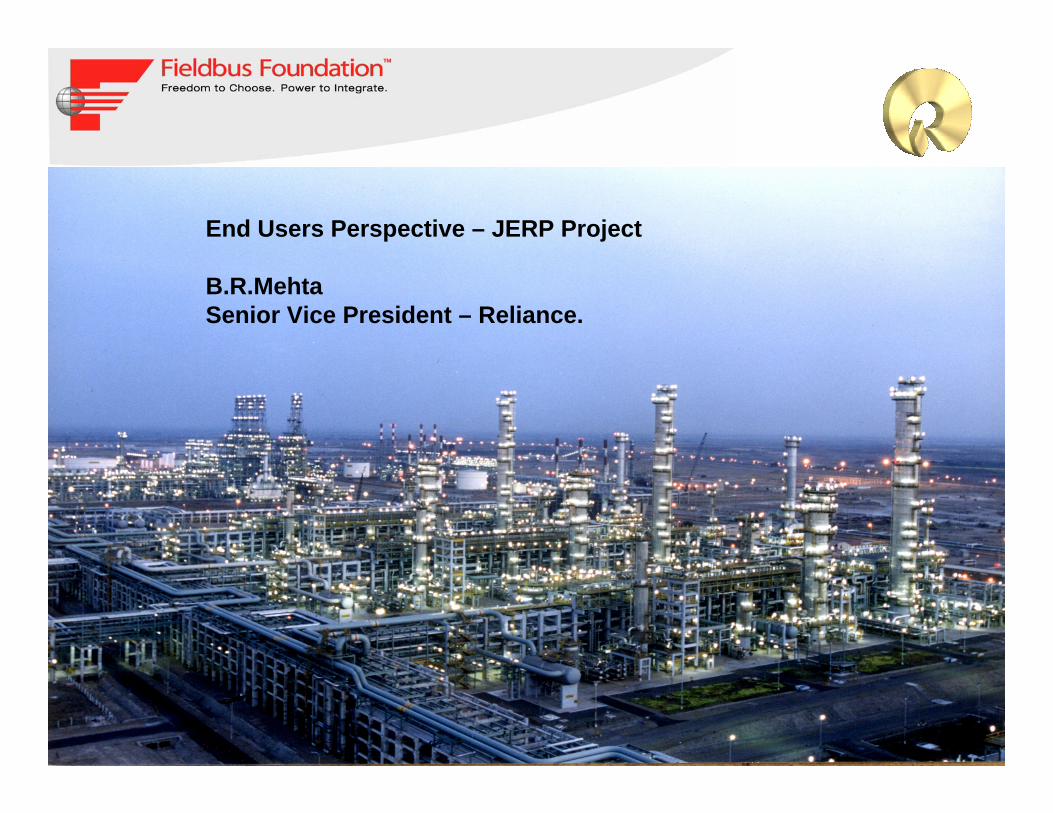
End Users Perspective – JERP Project
B.R.MehtaSenior Vice President – Reliance.


8
Fieldbus Overview - India
© 2007 Fieldbus Foundation


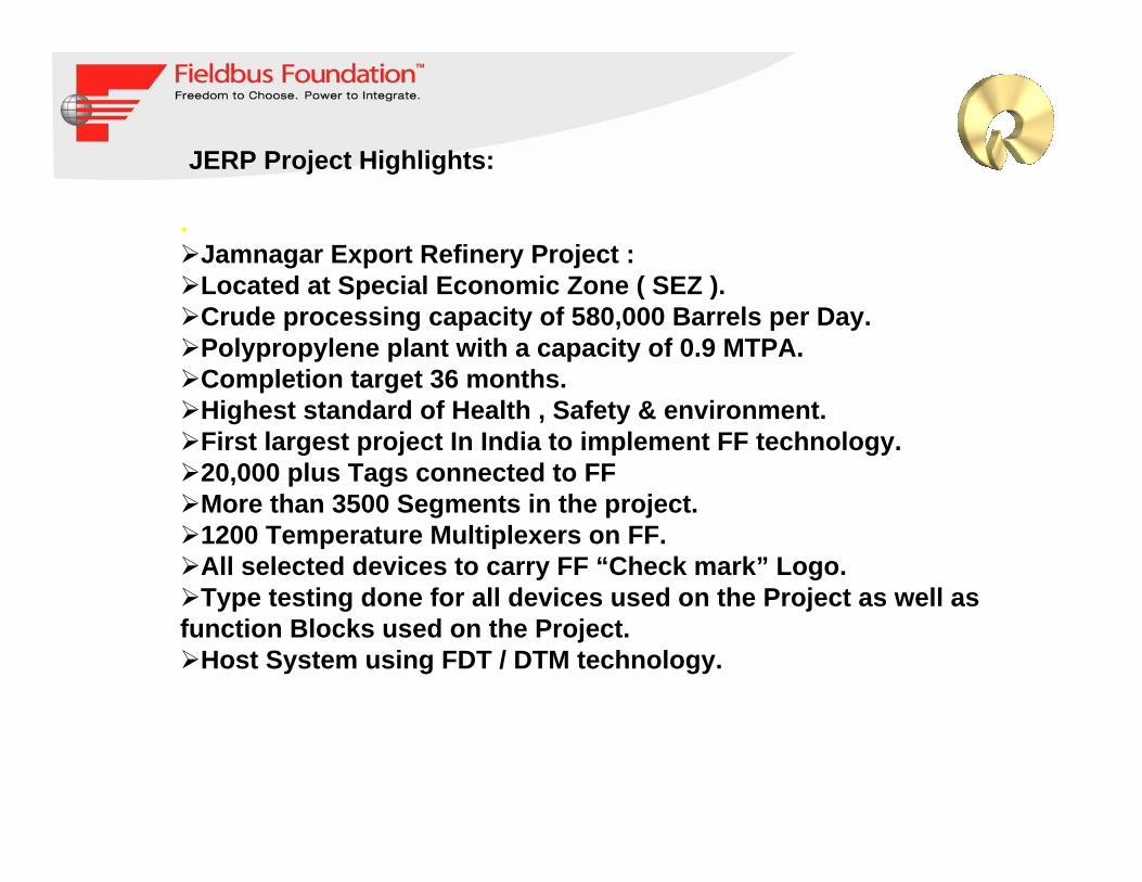
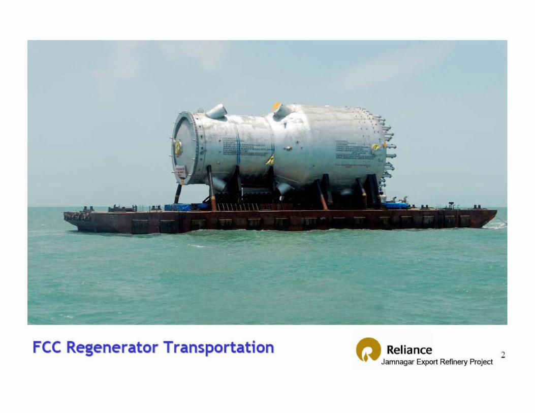
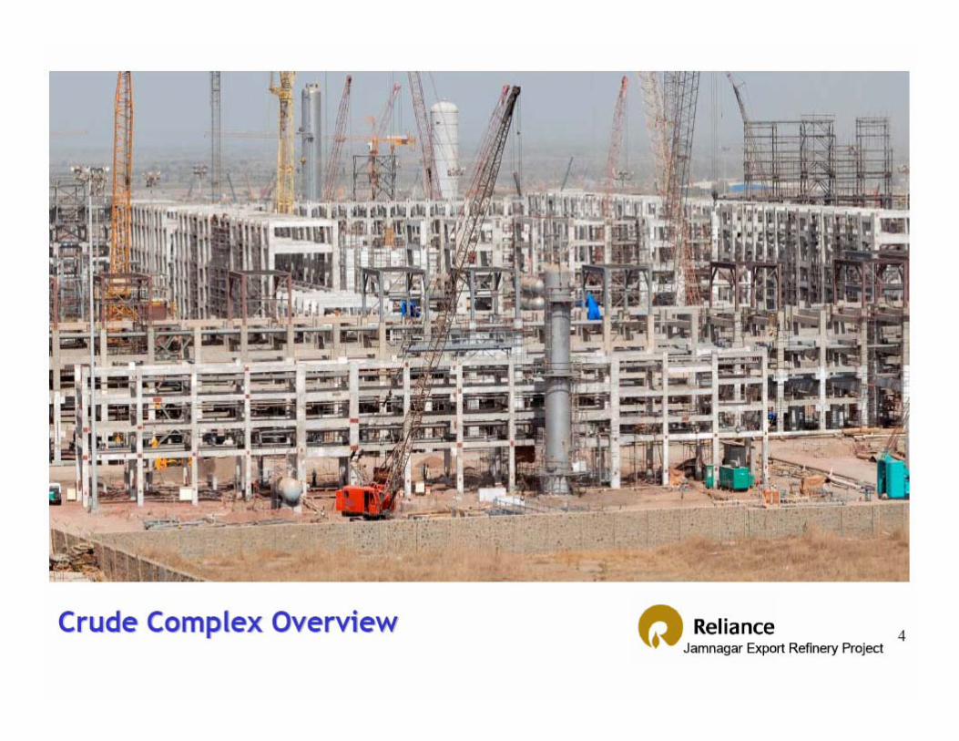
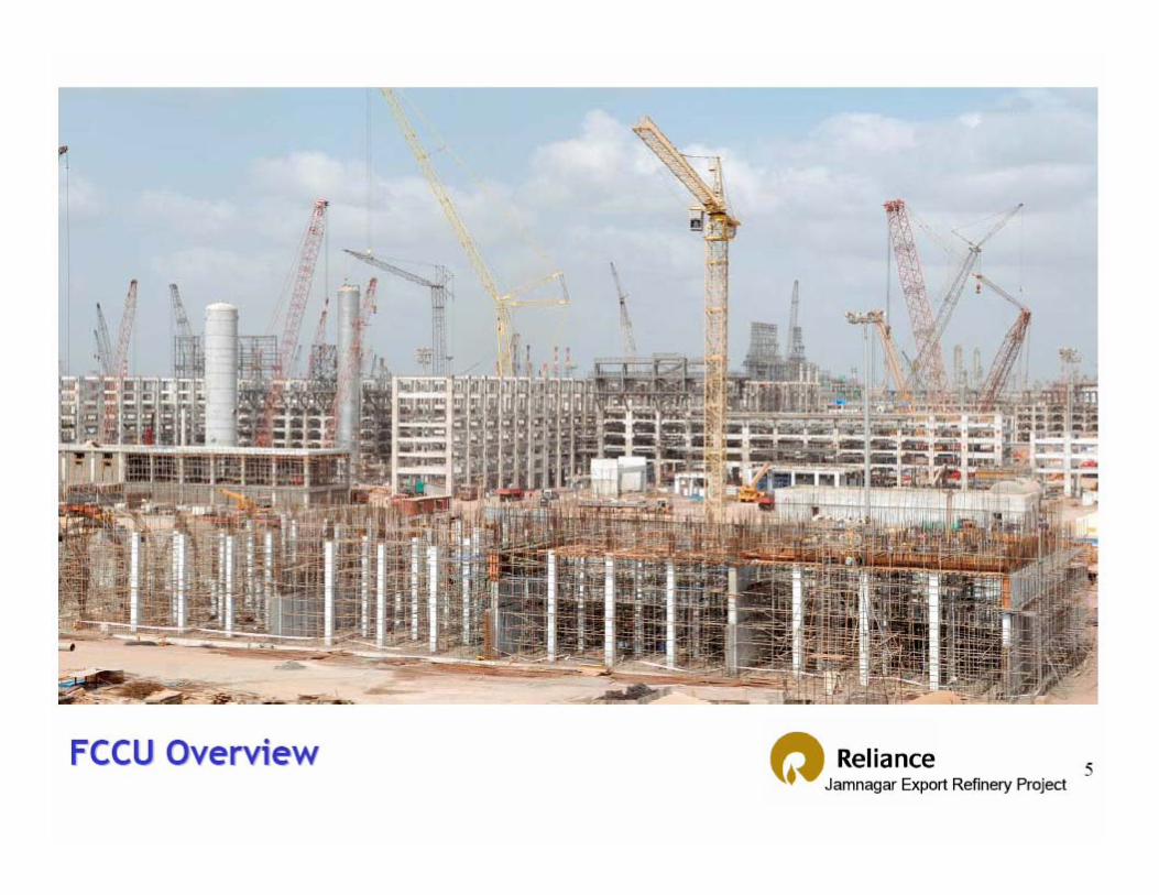
JERP Project Highlights:
.Jamnagar Export Refinery Project :Located at Special Economic Zone ( SEZ ).Crude processing capacity of 580,000 Barrels per Day.Polypropylene plant with a capacity of 0.9 MTPA.Completion target 36 months.Highest standard of Health , Safety & environment.First largest project In India to implement FF technology.20,000 plus Tags connected to FFMore than 3500 Segments in the project.1200 Temperature Multiplexers on FF.All selected devices to carry FF “Check mark” Logo.Type testing done for all devices used on the Project as well as
function Blocks used on the Project.Host System using FDT / DTM technology.

Our considerations :
.The future of Process Automation.
Life cycle stage
Proven Technology.First FF systems delivered more than 5 years ago.
Openness.Non Proprietary.Continuity to evolve.Adopt new technology.Interoperability

Innovators
Early Adopters
Early Majority
Late Majority
Laggards
Technology Adoption Cycle :
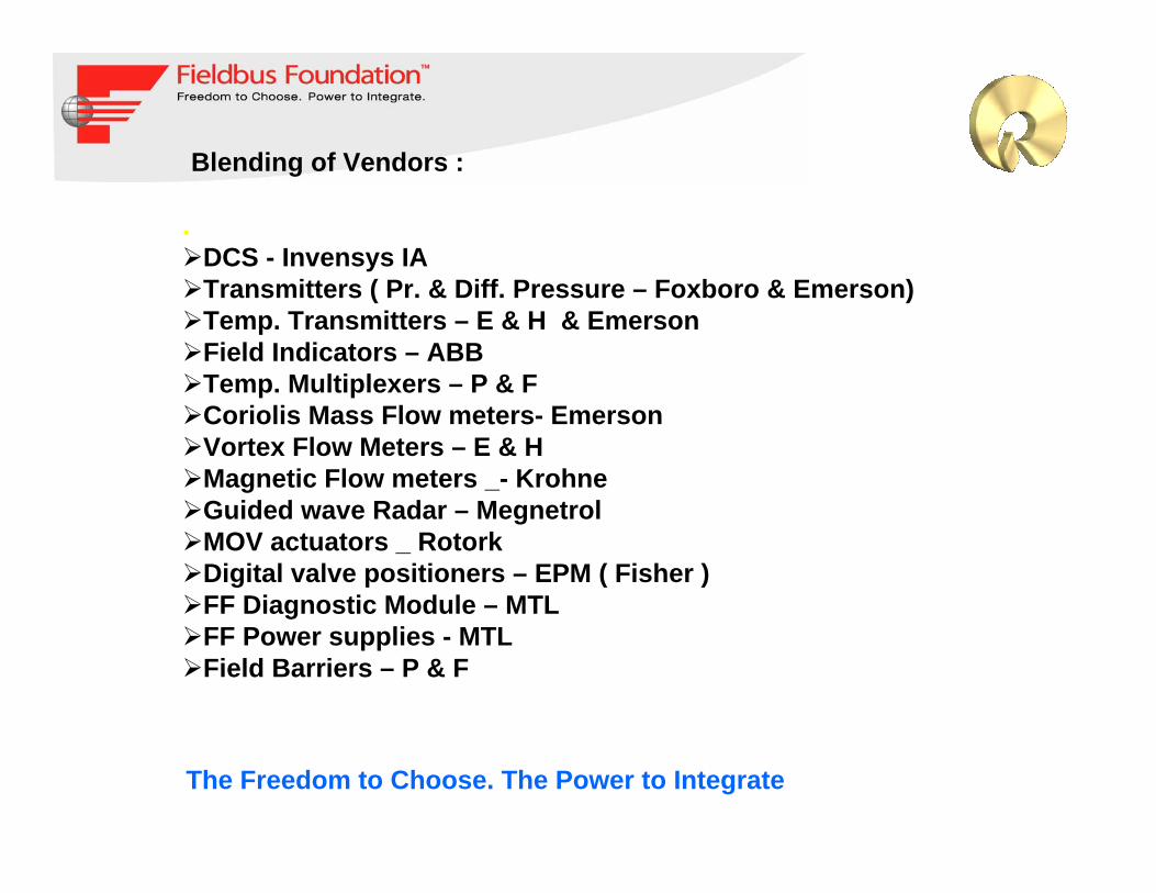
Blending of Vendors :
.DCS - Invensys IATransmitters ( Pr. & Diff. Pressure – Foxboro & Emerson)Temp. Transmitters – E & H & Emerson Field Indicators – ABBTemp. Multiplexers – P & FCoriolis Mass Flow meters- Emerson Vortex Flow Meters – E & HMagnetic Flow meters _- KrohneGuided wave Radar – MegnetrolMOV actuators _ RotorkDigital valve positioners – EPM ( Fisher )FF Diagnostic Module – MTLFF Power supplies - MTLField Barriers – P & F
The Freedom to Choose. The Power to Integrate
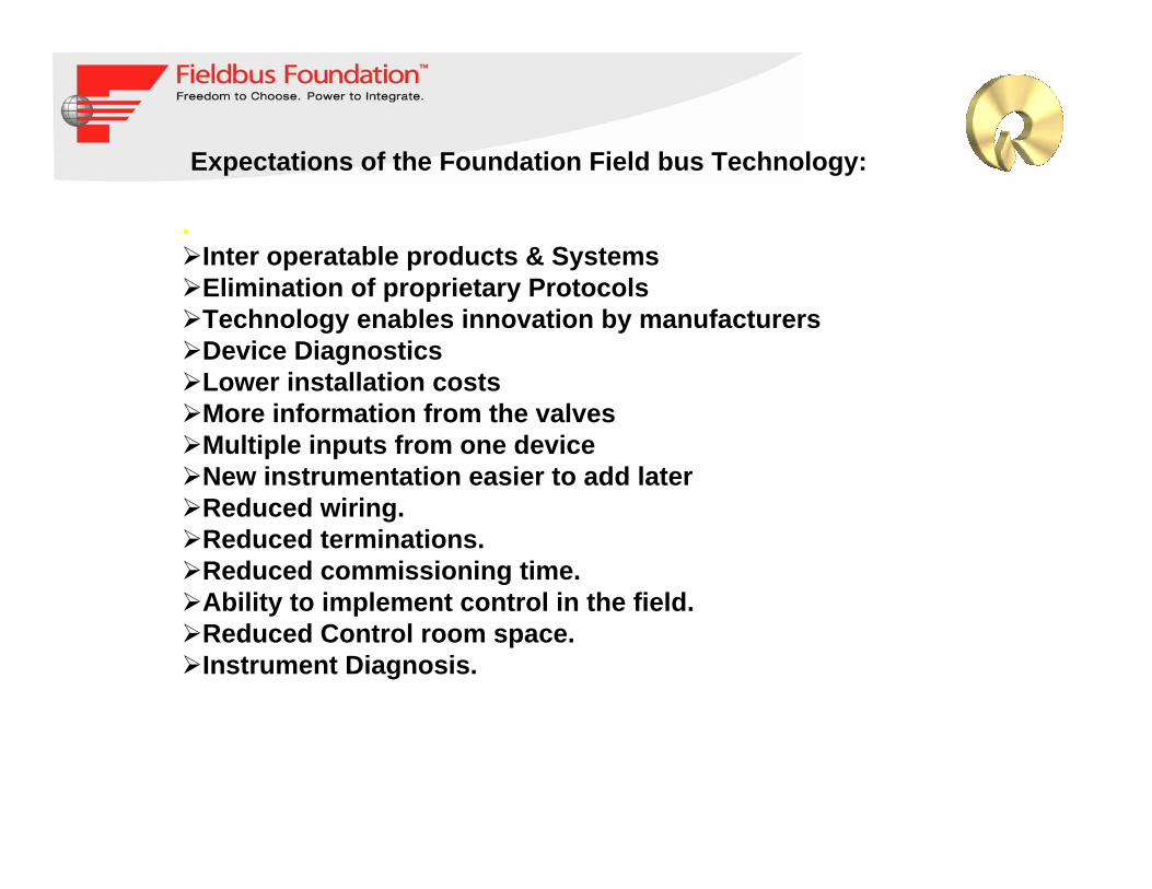
Expectations of the Foundation Field bus Technology:
.Inter operatable products & SystemsElimination of proprietary ProtocolsTechnology enables innovation by manufacturersDevice DiagnosticsLower installation costsMore information from the valvesMultiple inputs from one deviceNew instrumentation easier to add laterReduced wiring.Reduced terminations.Reduced commissioning time.Ability to implement control in the field.Reduced Control room space.Instrument Diagnosis.

The challenges:
.FF Technology relatively new in India as well as with foreign detail engineering contractors.Concurrent engineering at various locations around the world by Bechtel as well as interfaces with other engineering contractors like Foster Wheeler, Aker Kvaerner etc..Different skill set & experience required which is not available in IndiaVery large scale implementation at the same time with large workVolume.

Engineering Methodology adopted by Reliance:
.Early involvement of all parties including operation &
maintenance.Dedicated specification for Foundation Field bus
implementation.System & device selection & evaluation team with engineering
contractor.FF device HIST test programme with Invensys by testing each
device in their development laboratory in U.S.A..FF system design training for all involved personnel.FF system early set up of training at Invensys , India for pilot
testing dedicated to JERP project implementation.FF template development on IA system & testing of each
devices.FAT of devices along with system by connecting available
devices on a segment & loading of segments to its full capacity
Engineering Methodology adopted by Reliance:
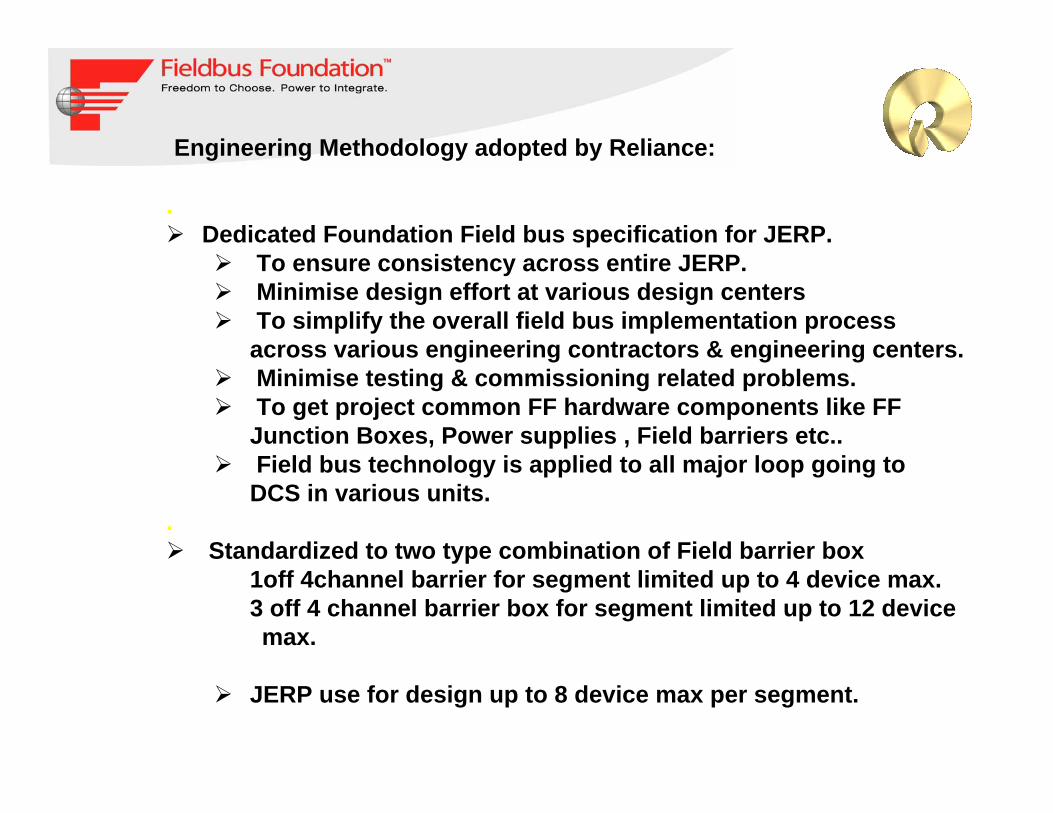
.Dedicated Foundation Field bus specification for JERP.
To ensure consistency across entire JERP.Minimise design effort at various design centersTo simplify the overall field bus implementation process across various engineering contractors & engineering centers.Minimise testing & commissioning related problems.To get project common FF hardware components like FF Junction Boxes, Power supplies , Field barriers etc..Field bus technology is applied to all major loop going to DCS in various units.
.Standardized to two type combination of Field barrier box
1off 4channel barrier for segment limited up to 4 device max.3 off 4 channel barrier box for segment limited up to 12 device max.
JERP use for design up to 8 device max per segment.

Engineering Methodology adopted by Reliance:
.Tree Topology adopted. JBF (Foundation
Fieldbus Junction Box)Trunk Cable
Spur Cable
FFPS
FFI
Surge protection:
All Trunks have surge protection at both ends i.e. in the marshalling cabinet and the FF spur junction box. Surge protection for each instrument shall be considered in areas with a high susceptibility to lightning strikes these areas include, tank farms, columns, jetties etc. and any areas where instrumentation is not significantly shielded by the plant steelwork and pipe racks.
Engineering Methodology adopted by Reliance:
.Segment design Considerations:
Level 1DefinitionFailure of level 1 loop will result in a shutdown of an entire unit, or damage to non-spared vital or essential equipment .
Level 1 valves and their associated measurement device should reside on a segment that are only used for Level 1 control. The segment will have one (1) Level 1 valve and associated Transmitter or maximum of two valves and associated transmitter if they are part of the same loop. Necessaryconsiderations shall be given to assign the valves to different barriers in the junction box.
Engineering Methodology adopted by Reliance:
.Segment design Considerations:
Level 2DefinitionFailure of a level 2 loop will result in entire unit shutdown but process dynamics allow for quick unit recovery.
Level 2 valves are only used for Level 2 control. The segment will have one (1) Level 2 valve and associated Transmitter or maximum of three valves (split range valves of a single loop) and associated transmitters if they are part of the same loop. Necessary considerations shall be given to assign thevalves to different barriers in the junction box.

Engineering Methodology adopted by Reliance:
.Segment design Considerations:
Level 3DefinitionFailure of a level 3 loop will not result in any short-term risk of total unit shutdown .
Level 3 valves can reside on segments with up to two other level 3 valves and not on a segment with a level 1 or level 2 valve.Reasonable reliability can be achieved with backfilling, particularly level 3 segments, with miscellaneous monitoring loops and local indicators.
Level 4 (No Control)Level 4 (monitoring only) segment contains monitoring devices are not to be used for control across segments.
Where FF Technology is not considered by Reliance:
.
Emergency Shutdown Systems.Fire & gas Control systems.Fast loops like Compressor Controls.( Anti Surge )Various packages like Heaters, Compressors.Loops with execution time faster than 300 ms.Burner Management system.Analyser Systems
Developments made by Solution Providers for FF:
FF Junction Boxes with 3 Field barriers & One Field Barrier developed by MTL using P & F Field Barriers.
Temperature Multiplexer Box developed by P & F.
8 Way base plate development for interface with Host system by MTL & Invensys.
Advance Diagnostic Module development for Segment Diagnostics by MTL.
Router DTM development by EPM & Invensys for Valve link .
Single Power supply kit by MTL for testing FF Segment.
Template development in Host system for all selected field devices by Invensys.

P & F- Field Barrier
MTL – Surge protector
ABB- Isolator
Spur Terminals
FF Junction Box with 3 Field barriers:
Stahl JB

FF Junction Box with one field Barrier:

FF Temperature Multiplexer :
Two Temperature Multiplexers per Junction BoxRepresents Two devices on a Segment.Maximum of 4 Temperature Multiplexers per Segment.All temperature Multiplexer segments are exclusive in JERP.

FF Power supply arrangement:
Power Supply Advance Diagnostic Module
FF FBMSurge Protector

8 Way Base plate consists of;
8 redundant power supplies for 8 segments
1 Advance Diagnostic module (ADM ) to monitor 8 segments Physical properties.
Two redundant set of FBM 228
Two Alarm module for hardwire alarm for segments connected.
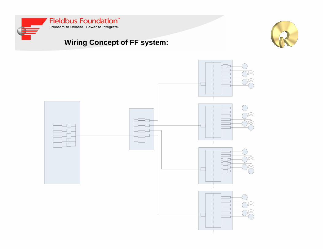
Wiring Concept of FF system:

FF Power Supply Module by MTL:

Virtual FF Virtual FF Linking DeviceLinking Device
HART HART Interface (XML)Interface (XML)
AMS AMS Device Device
ManagerManager
AMS AMS ValveLink SnapValveLink Snap--OnOn
Com
mun
icat
ions
Com
mun
icat
ions
Inte
rface
sIn
terfa
ces
Audit Trail Audit Trail ParserParser
AMS Logon /AMS Logon /Launch in Launch in
ContextContext
Dat
abas
eD
atab
ase
Rea
dR
ead
API
API
AMS Device Manager
Host SystemInterface
FDT ApplicationDevic
eDTM Process AutomationSystem
Communications DTM
EngineeringEnvironment
OperatorInterface
System SupplierValvelink -
I/O Subsystem
System Services
RouterDTM
Enhanced EDDs / EDDs
Router DTM Router DTM Communications Communications
ServerServer
FF and HART Router FF and HART Router DTMsDTMs development by EPM & Invensys:development by EPM & Invensys:

36
Fieldbus Overview - India
© 2007 Fieldbus Foundation
I/A Series Architecture
FCP270
FBM100 Series I/O
CP40B
Mesh Control Network
Version 6.x Version 8.xEngr. - ICC
Engr. - IACC
IACC = I/A Series Configuration ComponentICC = Integrated Control ConfiguratorFDSI = Field Device System IntegratorCBLI = Carrier Band LAN InterfaceDNBI = Dual Node Bus Interface
NodebusGW30B
ModbusAB DH+
FBM200 Series I/O
ModbusAB DH+AB ControLogix
FDSI
Nodebus
Carrier Band LAN CBLIDNBI

37
Fieldbus Overview - India
© 2007 Fieldbus Foundation
Technology Advancements since V6.0
Foundation FieldbusTraditional I/O
Graphical ConfigurationForms based Configuration
Mesh-based NetworkNodebus and Carrierband LAN
FCP270 and ZCP270CP40B
Field Device Systems Integration (FDSI)
GW30B
200 Series FBMs100 Series FBMs
V8.0V6.0
Alarm Points on the Project:
.How to Get faster Commissioning of FF Loops at site.
Mismatches in Device files tested at Lab versus devices supplied.
Untested device type delivered to site.
Alarm management implementation.
How to get Maximum out of Asset Management.
OPC Stability of many connected systems to DCS.
Training of Staff members in commissioning of FF system.
How to make FF Technology as Technology of Choice:
.Educate end users on FF technology in India.Assist end users in identifying the benefits of FF technology.Provide a Forum for the exchange of information among solution providers, consultants and end users.Assist end users in implementation of the technology.Encourage the adoption of FF technology in various sectors.Promote & support the FF technology and FF members on Vendor Neutral basis. Establish Communication between various FF country users.Co-ordinate activities among local members.Technical Seminars.End user meets.Training.Access to articles, applications, case studies from other countries. .
FF Technology V/S Legacy Systems:
The signals are digital therefore more immune to noise. The requirement for damping to filter out noise is eliminated.FF automatically detects all connected devices, and includes them on a live list.Addresses are automatically assigned, eliminating any possibility of duplicate addressing.Traditional I/O use 16 or 32 channel cards, these are costly and a weak point. Module failure can generally cause all associated loops to crash.Accidental removal during faultfinding will effect all 16 or 32 I/O.Minimise the components thus reduced failure probability.No requirement to manually configure alarms to detect transmitter failure or broken signal cable. Foundation Field bus builds in this automatic safety function.FF uses engineering units not scaled ranges, therefore you are measuring actual process variable not scaled or a % of 4-20mA. This eliminates the need for range configuration.Conflict in ranges is not possible. Analog to digital conversion removed, improving accuracy and reliability.Dual Measurement of parameters is possible from a single instrument.Failure Prediction is possible, due to the data available.

Thank You


![Profibus PA Fieldbus Display [ Revision 2 ] and Fieldbus ... Instruments... · Profibus PA Fieldbus Display [ Revision 2 ] and Fieldbus Indicator Fieldbus Interface Guide. ... Siemens](https://static.fdocuments.in/doc/165x107/5b2fe38e7f8b9ae16e8da83d/profibus-pa-fieldbus-display-revision-2-and-fieldbus-instruments.jpg)