
Network Field Day 10 - Juniper Networks Part 2: QFX10000 Architecture

Field Research Software™
Generic Harvest Module
Reference Guide

Juniper Systems and Allegro Field PC are registered trademarks of Juniper Systems, Inc. in the United States. Allegro CX, Archer Field PC, Field Research Software, FRS, FRS Note Taking, FRS Plot Harvest Data Modules, GrainGage, Classic GrainGage, USB/Power Dock, and the Juniper Systems logos are trademarks of Juniper Systems, Inc.
Reproduction of this reference guide without the written permission of Juniper Systems, Inc. is not allowed.
Information in this document is subject to change without notice. © October 2008, Juniper Systems, Inc. All rights reserved.
P/N 15307-01

iii
Contents
Software License Agreement 5
1 Introduction to FRS Harvest 7Getting Started: How to install FRS Harvest ..............9
2 Setting Up FRS Harvest™ 11
3 Calibrating and Preparing for Harvest 15Verify Weight Calibrations...............................................16Holding Hopper Function ...............................................22Moisture Sensor ................................................................23Timers ..................................................................................35Actuators ..............................................................................37Setup File .............................................................................38
4 Diagnostics Menu 41Load Cell ............................................................................. 43Moisture .............................................................................. 44LED Codes on the EM Grain Moisture Sensor ........ 46Actuators ............................................................................. 48Print Calibrations .............................................................. 49
5 Creating Traits and Templates for Harvest 51
Create harvest traits .........................................................52Create a Harvest Template .............................................55
iv
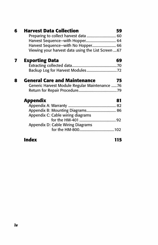
6 Harvest Data Collection 59Preparing to collect harvest data ................................ 60Harvest Sequence—with Hopper................................. 64Harvest Sequence—with No Hopper .......................... 66Viewing your harvest data using the List Screen ....67
7 Exporting Data 69Extracting collected data .................................................70Backup Log for Harvest Modules .................................72
8 General Care and Maintenance 75Generic Harvest Module Regular Maintenance ......76Return for Repair Procedure ..........................................79
Appendix 81Appendix A: Warranty .................................................... 82Appendix B: Mounting Diagrams ................................ 86Appendix C: Cable wiring diagrams
for the HM-401 ........................................92Appendix D: Cable Wiring Diagrams
for the HM-800 ......................................102
Index 115

5
Software License Agreement
Manufacturer Agreement
This Software License Agreement is between the end-user and Juniper Systems, Inc. (manufacturer). Please read the following terms and conditions before using Field Research Software with a handheld device. This agreement supersedes any prior agreement, written or oral.
Granting of License
The manufacturer grants, under the following terms and conditions, a non-exclusive license to use Field Research Software.
Ownership
Juniper Systems, Inc. retains the title to and ownership of the software plus any copies made of the software.
Software Use
The FRS license and registration are only valid on one handheld device per licensed copy. To purchase additional license copies, contact the manufacturer. You may make one copy of the software to be stored as a backup.
Copyright

6
Field Research Software is copyrighted by Juniper Systems, Inc. You may not rent, lease, lend, sub-license, modify, or disassemble this program. The associated documentation may not be reproduced without written permission.
Term
This License is in effect until terminated. It will be terminated under one of the following conditions:
You destroy all copies of the software and documentation.
You return all copies of the software and documentation to us.
You fail to comply with any provisions of the License Agreement.
Acceptance or Disagreement
Use of the software in any manner indicates your acceptance and acknowledgment of the terms and conditions of this agreement. If you do not agree with any of the terms and conditions, do not use the software. Return the disk and documentation to the manufacturer. If the software was installed on the mobile device at the factory, you must delete it.
•
•
•

Getting Started: How to install FRS Harvest
C H A P T e R 1
InTRODUCTIOn TO FRS Harvest

8
I n t r o d u c t i o n t o
F R S H a r v e s t
The Generic Harvest Module of the Field Research Software can be configured to work with a wide range of applications. It can be configured for standard forage type applications where no holding hopper is present and up to 3 load cells may be used. It is also used in two bucket grain systems with a holding hopper, a weight or plot bucket and a test chamber. With any of these applications, the number of load cells in use for the plot or weight bucket must be determined.
Designed by seed researchers, the Windows Ce based Field Research Software™ (FRS) helps seed researchers and agriculture scientists perform data collection tasks on research plots.
The Generic Harvest Module is employed on combines to record weight, moisture and test weight on grains or forages. It interfaces to a wide variety of buckets or measurement devices that make it adaptable to most any research combine or application. It aids research scientists by automating data collection. This Field Reference Guide helps you through the setup, calibration, and harvest with the FRS Generic Harvest Module.
C h a p t e r 1
9
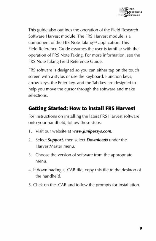
This guide also outlines the operation of the Field Research Software Harvest module. The FRS Harvest module is a component of the FRS Note Taking™ application. This Field Reference Guide assumes the user is familiar with the operation of FRS Note Taking. For more information, see the FRS Note Taking Field Reference Guide.
FRS software is designed so you can either tap on the touch screen with a stylus or use the keyboard. Function keys, arrow keys, the enter key, and the Tab key are designed to help you move the cursor through the software and make selections.
Getting Started: How to install FRS Harvest For instructions on installing the latest FRS Harvest software onto your handheld, follow these steps:
1. Visit our website at www.junipersys.com.
2. Select Support, then select Downloads under the HarvestMaster menu.
3. Choose the version of software from the appropriate menu.
4. If downloading a .CAB file, copy this file to the desktop of the handheld.
5. Click on the .CAB and follow the prompts for installation.

10
C h a p t e r 1

C H A P T e R 2
SETTInG UP FRS Harvest™
12
C h a p t e r 2
S e t t i n g U p F R S H a r v e s t ™
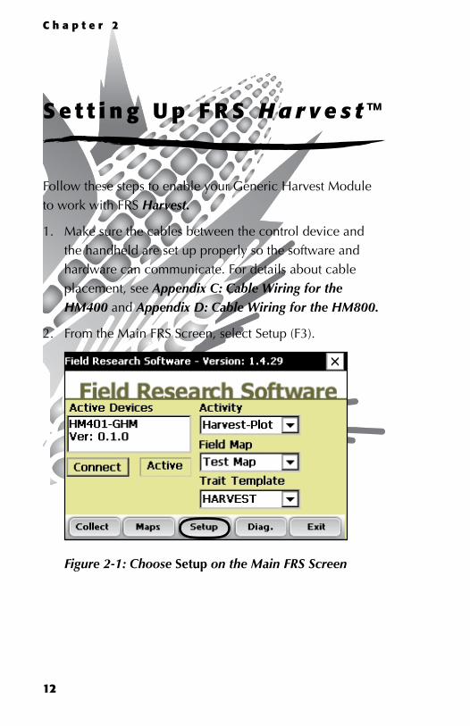
Follow these steps to enable your Generic Harvest Module to work with FRS Harvest.
1. Make sure the cables between the control device and the handheld are set up properly so the software and hardware can communicate. For details about cable placement, see Appendix C: Cable Wiring for the HM400 and Appendix D: Cable Wiring for the HM800.
2. From the Main FRS Screen, select Setup (F3).
Figure 2-1: Choose Setup on the Main FRS Screen

13
3. The setup menu appears. Tap on the plus sign [+] next to System or use the right arrow to expand the System option.
Figure 2-2: Setup menu
4. Select Manage Devices either by double-tapping it or by using the up or down arrow keys and pressing the enter key.
Figure 2-3: Setup menu with Manage Devices selected

14
C h a p t e r 2
5. In the Devices screen shown below, enable the Generic Harvest Module by tapping on the appropriate check box.
Note: Only one device can be enabled at a time.
Figure 2-4: Devices screen showing the Classic as enabled
6. Press Save (F4). The software begins to load and checks to see if hardware devices are connected. Wait until the software has finished loading before proceeding to the next chapter.
FRS software has an emulation mode to allow software familiarization without being connected to a hardware device.

C h a p t e r 3
CALIbRATInG AnD PREPARInG FOR
HARvEST
Weight Calibration
Moisture Sensor
GHM Config
Timers
Actuators
Setup File
16
Ca l ib ra t ing and Prepar ing
the Sys tem for Har ves t
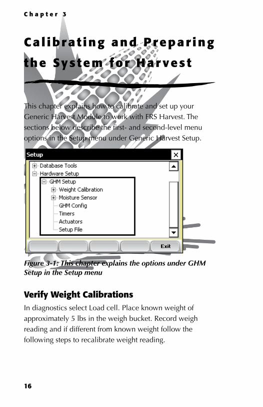
This chapter explains how to calibrate and set up your Generic Harvest Module to work with FRS Harvest. The sections below describe the first- and second-level menu options in the Setup menu under Generic Harvest Setup.
Figure 3-1: This chapter explains the options under GHM Setup in the Setup menu
verify Weight CalibrationsIn diagnostics select Load cell. Place known weight of approximately 5 lbs in the weigh bucket. Record weigh reading and if different from known weight follow the following steps to recalibrate weight reading.
C h a p t e r 3

17
Load Cell Calibration—Different Size and Single Load Cells
Before you can begin load cell calibration you must first determine the number of weigh or plot load cells being used by your system. Go to Hardware Setup > GHM Setup > GHM Config.
Figure 3-2: GHM Config
In the Generic Harvest Module Config screen, the user must specify the number of weigh or plot load cells in use.
In typical forage applications up to 3 load cells are installed. For standard grain buckets 1 plot load cell is used. A hopper and test chamber may be used as well. If a separate load cell is used to measure test weight, the test chamber should be selected and a valid chamber volume determined.
The AutoTare feature is also used in forage applications.
With AutoTare enabled, the software will zero out the weight readings after each plot is harvested rather than emptying the bucket of belt.

18
C h a p t e r 3
Figure 3-3: Generic Harvest Module Config screen
Manual calibration of multiple load cells can be accomplished by using one of two different methods. If you are using multiple load cells that are of the same size, skip to the section Load Cell Calibrating—Matching Load Cells. Single Load cells calibration should follow the procedure outlined below:

19
1. Load Cell Calibration—Different Load Cells. After you have determined the number of load cells go to Diagnostics Load Cell screen on the main menu.
Figure 3-4: Diagnostics Load Cell screen
2. From Diagnostics screen, place a known weight near load cell A. Write down the measured weight. Do the same for other load cells used in the system. Using the formula, below calculate the Cal Coef for each Load Cell
Cal Weight Ratio = Actual Weight / Measured Weight from Diagnostics
Example: 5.11 Actual / 4.80lbs measured = 1.0645833
Load Cell Cal Coef = Current Load Cell Cal Coef * Cal Weight Ratio
1.0645933 * 11.35 Load Cell Cal Coef for Load A = 12.08
Repeat this same step for Load B and Load C

20
C h a p t e r 3
3. To adjust load cell calibration, go to Setup > GHM Setup > Weight Calibration > Edit Weight Calibration. Up to 3 load cells can be calibrated and installed.
Figure 3-5: Edit Weight Calibration menu option
4. Type this New Cal Coef for all load cells into the correct text box and check in diagnostics.
Figure 3-6: Edit Weight Calibration screen

21
Load Cell Calibration—Matching Load Cells
If all three load cells are of the same size, follow these steps for calibration. For load cells of different sizes, please refer to Load Cell Calibration—Different Load Cells
1. Make sure all Load Cell Cal Coefficients are set to the same value.
2. Go to the Diagnostics-Load Cell Screen.
3. Tare the bucket if it is not zero.
4. Place a known weight in the center of the weigh bucket
5. Write down the measured Total Weight
6. Use the formula below to calculate the Load Cell Cal Coefficients
Cal Weight Ratio = Actual Weight / Measured Weight from Diagnostics
Example: 5.11 Actual / 4.80lbs measured = 1.0645833
Load Cell Cal Coef = Current Load Cell Cal Coef * Cal Weight Ration
1.0645933 * 11.40 Load Cell Cal Coef for Load A = 12.14

22
C h a p t e r 3
Type the New Cal Coef value into all 3 Load Cell Cal Coef in the edit Weight Calibration Screen.
Figure 3-7: Edit Weight Calibration screen
Holding Hopper FunctionThe Generic Harvest Module of FRS can be used in multiple applications. If a holding hopper or cyclone is installed it acts as a holding area for grain being harvested while grain already harvested is in the weigh bucket.
If no hopper is present in the system as is the case with forage machines, the product drops directly into the weigh bucket. AutoTare can also be enabled for forage type applications. For details on configuring the hopper or
23
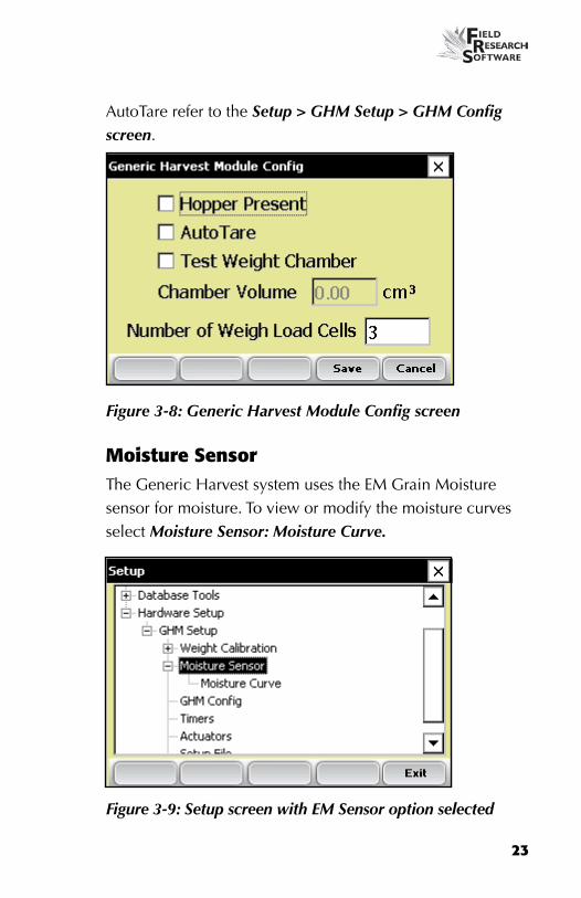
AutoTare refer to the Setup > GHM Setup > GHM Config screen.
Figure 3-8: Generic Harvest Module Config screen
Moisture SensorThe Generic Harvest system uses the eM Grain Moisture sensor for moisture. To view or modify the moisture curves select Moisture Sensor: Moisture Curve.
Figure 3-9: Setup screen with EM Sensor option selected

24
C h a p t e r 3
Moisture CurveEditing a moisture curveTo edit a moisture curve, follow these steps.
1. Select Setup (F3), then choose Hardware Setup > GHM Setup > Moisture Sensor > Moisture curve.
Figure 3-10: Setup screen with Moisture Curve screen selected
The Moisture Curve screen appears, listing any existing moisture curves and giving you the option to edit, delete, or copy moisture curves. each of these actions is described in more detail below.

25
Note: The check mark next to one of the curves indicates the curve most recently used.
Figure 3-11: Moisture Calibration main screen
The Moisture Calibration screen lists all moisture curves that have been created. One of the curves is a Default grain moisture sensor curve that comes with FRS. It can be copied but not modified. The default curve consists of a set of known data points, which the system uses when making the moisture measurement on a sample of grain. When plotted in a spreadsheet, the default curve appears like the graph (see Figure 3-12).
Default Moisture Curve for eM Sensor Moist % MV
0.00% 0.00 10.00% 1.22 13.00% 1.61 16.00% 1.93

26
C h a p t e r 3
19.00% 2.19 22.00% 2.41 25.00% 2.60 28.00% 2.77 31.00% 2.93 34.00% 3.07 37.00% 3.19 40.00% 3.30
45.040.035.030.025.020.015.010.05.00.0
0.00 1.00 2.00 3.00 4.00
Cal Method Cal Method
Figure 3-12: Default moisture curve as it appears in a spreadsheet (top) and as it appears in a graph (bottom)
To check moisture choose Diags (F4) on the main FRS screen then select Moisture. Record the Rel Vlts and the Moisture (%) from each sample that has been cycled through the grain gage. Compare the Moisture (%) reading with a known percent moisture from a standard.

27
Figure 3-13: Diagnostics Moisture screen
2. Adjust the moisture curve by adjusting individual points in the curve or by adjusting the value of the Calibration Temperature. The following sections explain how to make adjustments to individual points, how to adjust the moisture grain temperature, how to delete a curve, and how to copy a curve.
Note: We recommend creating a different moisture curve for each different grain type. A custom spreadsheet to aid in adjusting your moisture calibration can be found on the Juniper Systems web site. This spreadsheet helps you adjust the points on the moisture curve to match your system.
To access the spreadsheet, go to www.junipersys.com and choose Support > HarvestMaster > FAQs > Moisture Sensor (EM, High Capacity GrainGage, Classic GrainGage). Choose the link called EM Moisture Sensor Calibration to view the spreadsheet.
28
C h a p t e r 3
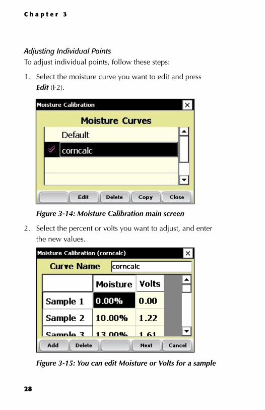
Adjusting Individual PointsTo adjust individual points, follow these steps:
1. Select the moisture curve you want to edit and press Edit (F2).
Figure 3-14: Moisture Calibration main screen
2. Select the percent or volts you want to adjust, and enter the new values.
Figure 3-15: You can edit Moisture or Volts for a sample

29
3. Press Next (F4) to save your changes to the moisture curve and advance to the Moisture Correction and Temperature screen.
Figure 3-16: Moisture Calibration Correction and Temperature screen
We recommend setting Temp Calibration to the current temp reading found in the diagnostics menu.
Note: When grain moisture readings are harvested at a different temperature than the temperature during the original calibration, the grain moisture measurement needs to be corrected to adjust for this difference. The Generic Harvest Module automatically makes this moisture correction based on the Temp Calibration and Moisture Correction Multiplier found in the screen above.
4. When you are finished editing your moisture curve, press Save (F4) to exit and save your changes.

30
C h a p t e r 3
Adjusting the Grain Moisture TemperatureYou can also use the temperature calibration to make small adjustments to moisture readings taken by the system. To change the temperature calibration to match your grain samples, follow these steps:
1. From the Main FRS screen, Select Setup (F3), then Hardware Setup > GHM Setup > Moisture Sensor > Moisture Curve.
2. Select a moisture curve then select Edit (F2) or Copy (F4).
3. Tap Next (F4). The Moisture Correction and Temperature screen appears.
Figure 3-17: Moisture Correction and Temperature screen for the “corncalc” curve
even though the moisture correction is automatic, changing the Temp Calibration shifts all moisture readings up or down, depending on if the temperature was increased or decreased. If you find that your new moisture reading is consistently high over the whole range, you can lower the calibration temperature to

31
decrease all moisture readings. You can also raise the calibration temperature if your moisture is consistently too low. This is an easy way to fine-tune the moisture curve after calibration.
Follow these steps to calculate the proper temperature adjustment:
1. If the system provides a different moisture value than your actual moisture value (e.g., 19.5% instead of 18.5%) and you’d like to adjust it, use this formula to figure out the calibration value:
(Actual Moisture – HDS Moisture)/ Moisture Correction Multiplier = Mstr. Temperature Calibration
example: 18.5%–19.5%/0.092 = –10.87 C
2. Next, add this value to your existing temperature.
Note: If the calibration value you calculated in Step 1 is negative as in the example above, keep the negative sign.
In this example, assume the existing temperature calibration is 27 C:
Temp Calibration + Mstr Temp Cal = New Temp Calibration
Example: 27.0 + (–10.87) = 16.13
3. Save any changes you made to the settings on the Moisture Correction and Temperature screen by pressing Save (F4). You can check the moisture calibration by pressing Diag (F3) before saving your changes.

32
C h a p t e r 3
Deleting a CurveThe Delete option in the Moisture Curve menu allows you to remove unwanted moisture curves. To delete an unwanted moisture curve, follow these steps:
1. Select the curve you want to delete and press Delete (F3).
Figure 3-18: Delete a moisture curve by selecting it and tapping Delete (F3)
2. Confirm the delete by tapping Yes or No.
Figure 3-19: Warning screen
33
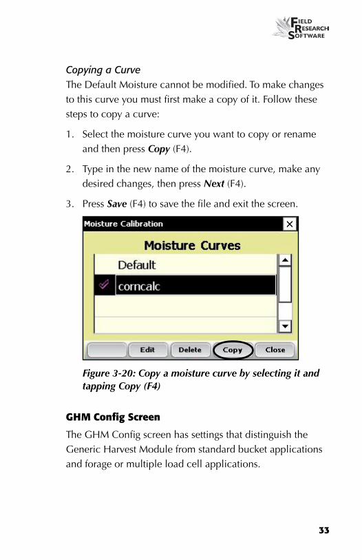
Copying a CurveThe Default Moisture cannot be modified. To make changes to this curve you must first make a copy of it. Follow these steps to copy a curve:
1. Select the moisture curve you want to copy or rename and then press Copy (F4).
2. Type in the new name of the moisture curve, make any desired changes, then press Next (F4).
3. Press Save (F4) to save the file and exit the screen.
Figure 3-20: Copy a moisture curve by selecting it and tapping Copy (F4)
GHM Config Screen
The GHM Config screen has settings that distinguish the Generic Harvest Module from standard bucket applications and forage or multiple load cell applications.

34
C h a p t e r 3
Choose Setup (F3) on the main FRS screen, then select Hardware Setup > GHM Setup > GHM Config.
Figure 3-21: Generic Harvest Module Config screen
Check Hopper when a hopper or cyclone is present. This changes the sequencing of buckets in harvest.
Check the AutoTare box in forage applications where the bucket will be tared or set to zero after each plot instead of emptying the bucket.
Test Weight Chamber volume
In a standard two bucket system, a chamber or bucket may be used to determine test weight. To view or change the test weight chamber volume follow these steps:
1. Choose Setup (F3) on the main FRS screen, then select Hardware Setup > GHM Setup > GHM Config.
2. The test weight volume can vary from bucket to bucket. It is important to determine the volume in Cubic Inches or Cubic Centimeters of the test chamber in order to have accurate test weight.

35
3. To verify test weight accuracy take a grain sample and verify test weight from a known test weight measurement device. Cycle the grain sample through the system to get a measured test weight. If the test weight measured by the bucket does not match the test weight from a standard the chamber volume can be adjusted.
4. To adjust the test weight reading from the system use the following formula
New Chamber Volume = measure test weight/actual test weight * chamber volume
Example: 56.2 lbs/bu / 58.8 * 89 = 85 cu inches.
Type the new test weight chamber volume into the text box. For metric conversion the test chamber and test weight should be in cu cm and kg/hl.
Timers The Timer screen is used to adjust various timers used with the system. each of these timers can be adjusted using the Timer Setup screen, which is available by choosing Setup (F3) from
36
C h a p t e r 3
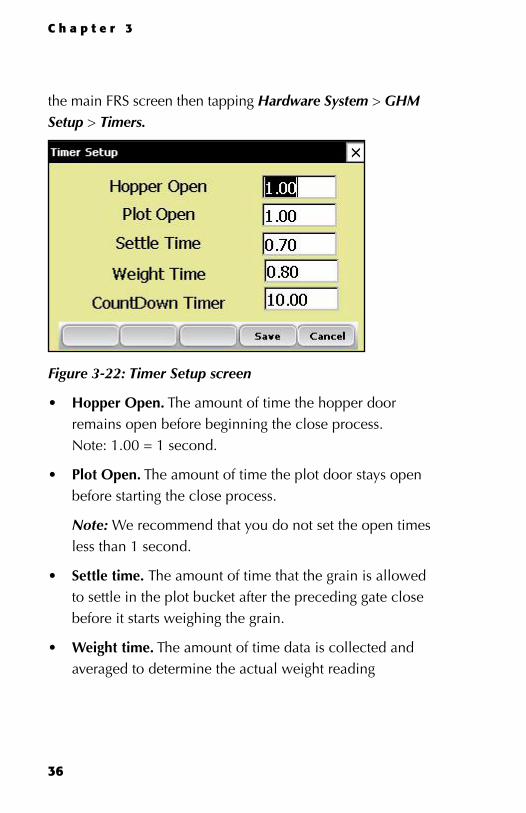
the main FRS screen then tapping Hardware System > GHM Setup > Timers.
Figure 3-22: Timer Setup screen
hopper Open. The amount of time the hopper door remains open before beginning the close process. Note: 1.00 = 1 second.
plot Open. The amount of time the plot door stays open before starting the close process.
Note: We recommend that you do not set the open times less than 1 second.
Settle time. The amount of time that the grain is allowed to settle in the plot bucket after the preceding gate close before it starts weighing the grain.
Weight time. The amount of time data is collected and averaged to determine the actual weight reading
•
•
•
•

37
CountDown timer. The amount of time from when the enter key is pressed until the system starts to cycle. Usually equal to the time it takes for the combine to clean out or the time it takes for the grain to travel from the head of the combine to the hoppers. Note: 1.00 = 1 second.
ActuatorsThe Actuator Setup screen is used to select the appropriate type of actuator and transition times for your system. To access the screen, choose Setup (F3) on the main FRS screen then tap Hardware Setup > GHM Setup > Actuators.
Figure 3-23: Double-tap Actuators from the Setup menu to access the Actuator Setup screen
Once you see the Actuator Setup screen, select the appropriate actuator type from the drop-down menu for each actuator.
•

38
C h a p t e r 3
Figure 3-24: Actuator Setup screen
If limit switches are being used check the boxes accordingly. If limit switches are not being used, enter the time in seconds needed for the stroke of the actuator to fully extend or retract. In the example above, the limit switch is enabled for the Hopper (top) on the closing transition only. On the opening transition, a time of 0.8 seconds controls the actuator.
Setup FileThe Setup File option on the Setup menu is a way to establish specific settings for a specific machine. This is helpful if you want to use your handheld with more than one combine. The steps below explain how to establish setup files for two combines.
1. Set up and calibrate one combine.

39
2. enter the Setup File screen by double-tapping Setup File in the Setup menu. A list of existing setup files appears.
Figure 3-25: Setup files that appear by default
By default, the settings you created when you set up and calibrated the handheld were saved to the Default setup file.
3. To create a setup file for a second combine, tap Save (F4).
Figure 3-26: Naming a new setup file

40
C h a p t e r 3
4. Create a name for the second setup file.
5. Repeat steps 1–2. The new setup file appears.
Figure 3-27: The new setup file appears
6. As you can see in the first column, this second setup file is now the active file, which means that any setting and calibrations changes you make are automatically saved to that file. To make another setup file active, select it then tap Select.
To create setup files for additional machines, repeat the process.

C H A P T e R 4
DIAGnOSTICS MEnU
Load Cell
Moisture
Actuators
Print Calibrations
42
C h a p t e r 4
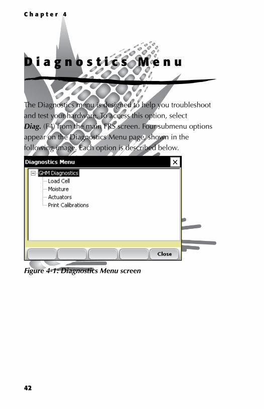
D i a g n o s t i c s M e n u
The Diagnostics menu is designed to help you troubleshoot and test your hardware. To access this option, select Diag. (F4) from the main FRS screen. Four submenu options appear on the Diagnostics Menu page, shown in the following image. each option is described below.
Figure 4-1: Diagnostics Menu screen
43
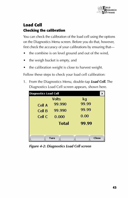
Load CellChecking the calibration
You can check the calibration of the load cell using the options on the Diagnostics Menu screen. Before you do that, however, first check the accuracy of your calibrations by ensuring that—
the combine is on level ground and out of the wind,
the weigh bucket is empty, and
the calibration weight is close to harvest weight.
Follow these steps to check your load cell calibration:
1. From the Diagnostics Menu, double-tap Load Cell. The Diagnostics Load Cell screen appears, shown here.
Figure 4-2: Diagnostics Load Cell screen
•
•
•

44
C h a p t e r 4
2. Make sure the weight values for Cell A, Cell B, Cell C and the total weight all equal close to zero. If not, tare the system by selecting Tare (F2).
Figure 4-3: Weight values for Cell A, Cell B, Cell C and Total change after a tare
3. Place your known weight into weigh bucket.
4. The weight shown in the Total line should match your known weight. If the weight is incorrect, recalibrate the load cells by returning to the main FRS page and selecting Setup > Hardware Setup > GHM Setup > Weight Calibration.
MoistureThe Moisture option allows you to view readings associated with the eM Grain Moisture sensor.
45
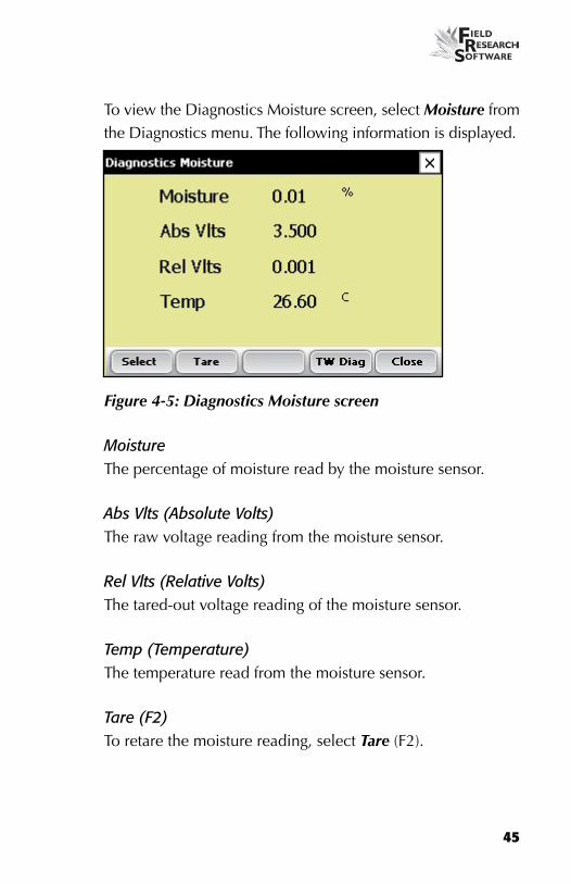
To view the Diagnostics Moisture screen, select Moisture from the Diagnostics menu. The following information is displayed.
Figure 4-5: Diagnostics Moisture screen
MoistureThe percentage of moisture read by the moisture sensor.
Abs Vlts (Absolute Volts)The raw voltage reading from the moisture sensor.
Rel Vlts (Relative Volts)The tared-out voltage reading of the moisture sensor.
Temp (Temperature)The temperature read from the moisture sensor.
Tare (F2)To retare the moisture reading, select Tare (F2).

46
C h a p t e r 4
Select (F1)Tapping this soft key opens the moisture curve menu screen, allowing you to select a moisture curve to be used for checking calibration. Select the curve and then tap Select (F1) again to return to the previous screen.
LED Codes on the EM Grain Moisture SensorGreen, yellow, and red LeD’s (light emitting diode) are designed into the sensor for service and diagnostics purposes. These LeD’s can be viewed by looking at the right side of the white plastic housing of the sensor. The function of the LeD’s are described as follows.
Green: On solid when +12 VDC is applied to the sensor
Yellow: Blinks whenever a message is transmitted from the sensor such as when the application software is in the moisture diagnostics menu.
Red: Indicates sensor error conditions. With no error codes, the red alternates one second on, then one second off.
Any error codes are represented by pairs of ‘rapid blinking’, the number of blinks corresponding to the first and second digit of an error code from the list below:
11. Watchdog reset has occurred
12. Timed Task Buffer overflow detected
13. Low memory alert (M < 50 bytes)
21. Input buffer overrun

47
22. Checksum error detected
23. Unrecognized command received by sensor
24. RS-485 busy encountered
25. Sensor response message aborted
32. Frequency measurement zero error (no oscillation counts)
33. Frequency measurement range error (over 3 Mhz)
41. Blade voltage range error
42. Temperature sensor zero error (reading at or below –15 C (5 F)
43. Temperature sensor range error (reading above +60 C )
44. System supply voltage below +10.0 Volts
45. System voltage above +18.0 Volts
55. Invalid error code reported
When the sensor is operating normally, no error codes should show. There should just be a steady one second on, one second off blink of the red. Otherwise, general interpretation would be:
11, 12, 13, 55: Software system problems. Report to customer service and design engineering with description of circumstances.
21, 22, 23, 24, 25: Faulty sensor wires, or faulty SCCU. These could be caused by some fault within the eMGS, but it is not likely.

48
C h a p t e r 4
32, 33, 41: Likely cause would be a bad connection from the sensor to the ground plane around the blade, or from the sensor board to the blade.
42, 43: Assuming the temperature is in a normal ambient range from -10 C to +40 C, these codes would indicate a failed temperature sensor, or board solder connection.
44,45: These are more likely caused by a problem in the power supplied to the eMGS.
ActuatorsThis Actuator Controls screen allows you to open, close, or cycle any or all of the actuators. To access this screen, select Diag. (F4) from the main FRS screen, then select Actuator. The Actuator Controls screen appears.
Figure 4-8: Actuator Controls screen

49
Print CalibrationsThe Print Calibrations menu allows you to print your calibration settings. To print, simply select one of the calibration options and tap Print (F1).
Figure 4-9: Print Calibrations screen

50
C h a p t e r 4

Create harvest traits
Create a Harvest Template
CHAPTeR 5
CREATInG TRAITS AnD TEMPLATES
FOR HARvEST

52
C h a p t e r 5
C r e a t i n g T r a i t s a n d
T e m p l a t e s f o r H a r v e s t
Create harvest traitsBefore you can collect harvest data, you first need to add or select harvest traits from the Master Traits List and then create a harvest trait template for these new traits. FRS includes sample harvest traits and templates. You can create your own traits or modify the traits that are included with FRS.
Note: It is especially important that traits that reflect data from the Generic Harvest Module, such as moisture and weight, are set up correctly in order for the software to register data from the hardware. If these traits are not set up correctly, data will not be recorded from these devices.
Adding a trait to the Master Traits List
Follow these steps to add a trait to the Master Trait List:
1. Open the Master Traits List screen by choosing Setup (F3) and double-tapping Traits Management.
53
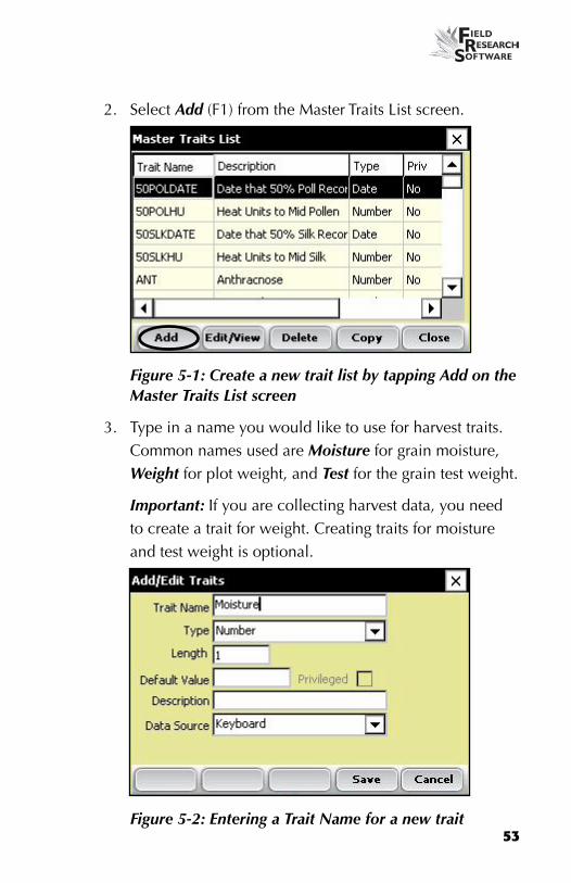
2. Select Add (F1) from the Master Traits List screen.
Figure 5-1: Create a new trait list by tapping Add on the Master Traits List screen
3. Type in a name you would like to use for harvest traits. Common names used are Moisture for grain moisture, Weight for plot weight, and Test for the grain test weight.
Important: If you are collecting harvest data, you need to create a trait for weight. Creating traits for moisture and test weight is optional.
Figure 5-2: Entering a Trait Name for a new trait
54
C h a p t e r 5
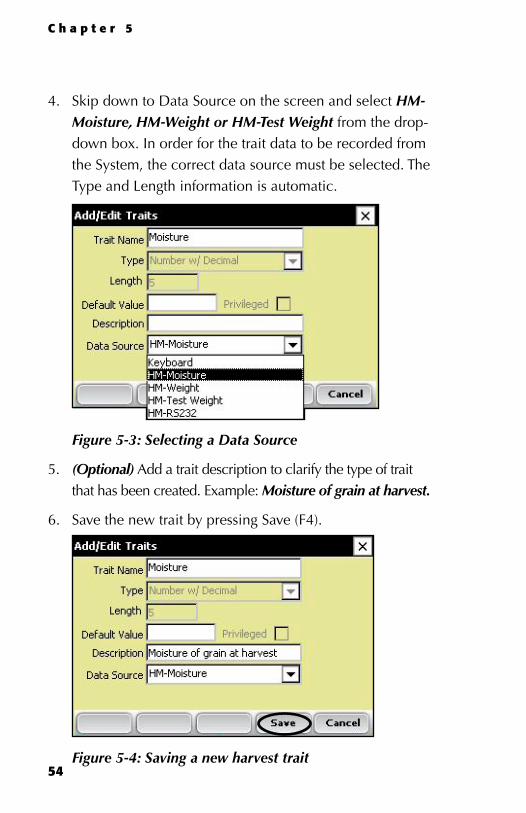
4. Skip down to Data Source on the screen and select HM-Moisture, HM-Weight or HM-Test Weight from the drop-down box. In order for the trait data to be recorded from the System, the correct data source must be selected. The Type and Length information is automatic.
Figure 5-3: Selecting a Data Source
5. (Optional) Add a trait description to clarify the type of trait that has been created. example: Moisture of grain at harvest.
6. Save the new trait by pressing Save (F4).
Figure 5-4: Saving a new harvest trait

55
Create a Harvest TemplateAfter you have added harvest traits to the Master Trait List, create a trait template that contains these new traits.
To create a trait template, follow these steps:
1. From the Setup Menu, expand the Traits Management option and double-tap Trait Templates.
Figure 5-5: Double-tap trait templates to open the Trait Templates screen
Figure 5-6: Trait Templates screen

56
C h a p t e r 5
2. Select Add (F1) to create a blank template. The Add/edit Trait Templates screen appears.
Figure 5-7: Add/Edit Trait Templates screen
3. Type a Template Name and Description to help identify the template. (Harvest or Harvest Data are suggested template names.)
4. Scroll down through the Master Traits List to find the Weight, Moisture and Test Weight traits you created. Highlight one of the traits, then tap on the Right Arrow in the middle of the screen to move it to the Current Traits window. In the example below, Weight, Moisture, and Test traits have been added as Current Traits.

57
Note: You can change the trait order by tapping on the up or down arrows on the screen.
Figure 5-8: New template called Harvest
Note: In some applications moisture or test weight may NOT be required. Do not include these traits into the template if they are not to be collected.
5. Press Save (F4) to save the new template.

58
C h a p t e r 5
Preparing to collect harvest data
Harvesting and collecting data
Viewing your harvest data using the List Screen
CHAPTeR 6
HARvEST DATA COLLECTIOn

60
C h a p t e r 6
H a r v e s t D a t a C o l l e c t i o n
After you have calibrated the Generic Harvest Module, created harvest traits, and created a new harvest trait template, you are now ready to collect data. This chapter explains how to prepare for, collect, and view harvest data using FRS. For addition information, refer to the FRS Field Reference Guide (Note Taking).
Preparing to collect harvest dataFollow these steps to prepare FRS to collect harvest data:
1. On the FRS Main Screen, make sure the Active Devices box shows GHM in the Setup menu under System > Manage Devices.
Figure 6-1: The Generic Harvest Module appears in the Active Devices box

61
2. Select the appropriate activity from the Activity drop-down menu on the FRS Main Screen. For example, if you plan to use FRS for harvesting, select the Harvest Activity. For standard plot lengths, set the activity to Harvest-Plot.
3. On this same screen, select the correct field map name from the pull down menu.
Note: If you need a new field map for harvest, create one before proceeding to the next step. Refer to the FRS Note Taking Field Reference Guide (Note Taking) manual for instructions on creating a new field map.
4. Select the trait template you want to use from the Trait Template drop-down box. Options include the harvest traits you created such as Weight, Moisture or Test Weight.
5. Select Collect (F1) to enter data collection mode. The Moisture Calibration screen appears.
Note: If a moisture is not included in the Trait Template or is being recorded, this screen does not appear.
Figure 6-2: Moisture Calibration screen
62
C h a p t e r 6
6. Select a moisture curve from the list, then tap Select (F1). Wait while harvest set ups are loaded.
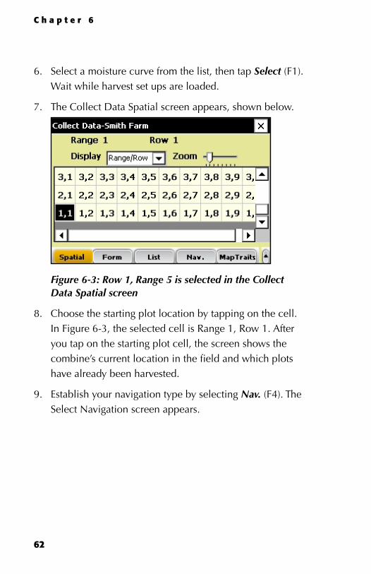
7. The Collect Data Spatial screen appears, shown below.
Figure 6-3: Row 1, Range 5 is selected in the Collect Data Spatial screen
8. Choose the starting plot location by tapping on the cell. In Figure 6-3, the selected cell is Range 1, Row 1. After you tap on the starting plot cell, the screen shows the combine’s current location in the field and which plots have already been harvested.
9. establish your navigation type by selecting Nav. (F4). The Select Navigation screen appears.
63
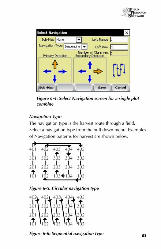
Figure 6-4: Select Navigation screen for a single plot combine
Navigation TypeThe navigation type is the harvest route through a field. Select a navigation type from the pull down menu. examples of Navigation patterns for harvest are shown below.
401 402 403 404 405
301 302 303 304 305
201 202 203 204 205
101 102 103 104 105
Figure 6-5: Circular navigation type
402 402 403 404 405
301 302 303 304 305
201 202 203 204 205
101 102 103 104 105
Figure 6-6: Sequential navigation type
64
C h a p t e r 6
401 402 403 404 405
301 302 303 304 305
201 202 203 204 205
101 102 103 104 105
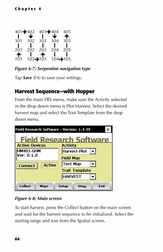
Figure 6-7: Serpentine navigation type
Tap Save (F4) to save your settings.
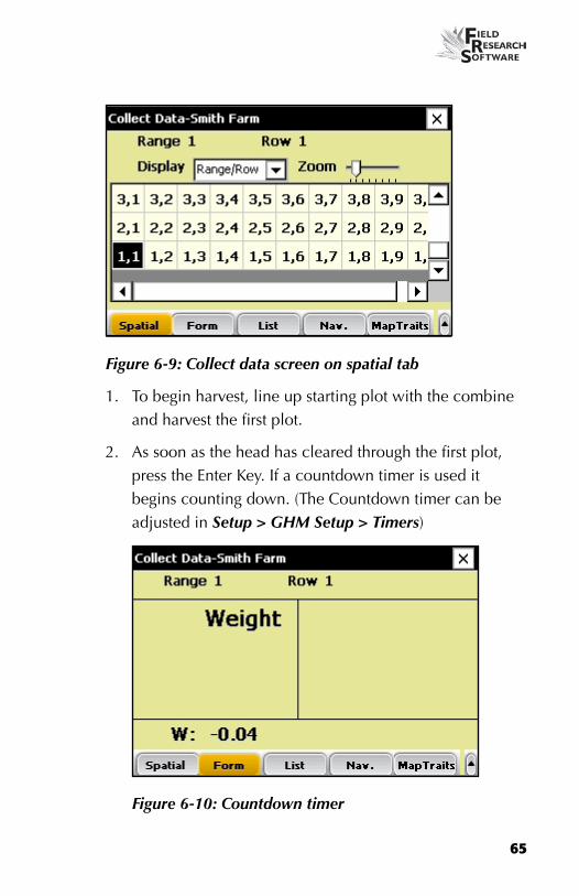
Harvest Sequence—with HopperFrom the main FRS menu, make sure the Activity selected in the drop down menu is Plot Harvest. Select the desired harvest map and select the Trait Template from the drop down menu.
Figure 6-8: Main screen
To start harvest, press the Collect button on the main screen and wait for the harvest sequence to be initialized. Select the starting range and row from the Spatial screen.
65
Figure 6-9: Collect data screen on spatial tab
1. To begin harvest, line up starting plot with the combine and harvest the first plot.
2. As soon as the head has cleared through the first plot, press the enter Key. If a countdown timer is used it begins counting down. (The Countdown timer can be adjusted in Setup > GHM Setup > Timers)
Figure 6-10: Countdown timer

66
C h a p t e r 6
3. If a hopper or cyclone door present and enabled the sequence is difference on the first plot harvested.
4. The Hopper door will open when the enter key is pressed emptying its contents into the weigh bucket.
5. The driver should harvest the second plot letting it fill up the holding hopper. As soon as all grain is in the holding hopper the enter key is pressed again.
6. The traits that have been enabled will be taken on the grain in the weigh bucket.
Figure 6-11: All three traits collected
7. After the plot bucket door empties out, the hopper will open emptying its contents into the weight bucket.
8. The driver can start into the next plot and the sequence starts again.
Harvest Sequence—with no HopperIf a hopper is not enabled product is taken directly to the plot or weigh bucket. Data are recorded in the plot bucket

67
after the enter key is pressed rather than filling into the hopper.
In applications where no hopper is present such as on forage machines.
AutoTare feature may be enabled. To set the AutoTare feature go Setup > Hardware Setup > GHM Setup > GHM Config.
viewing your harvest data using the List ScreenBy selecting List (F3), you can view your harvest data. Note: You CANNOT collect harvest data while you are in this screen. To harvest, you must be in the Form screen. See the section above called Plot Harvest Sequence for details.
Figure 6-12: List screen showing moisture, test weight, and weight values for each plot

68
C h a p t e r 6

extracting collected data
Backup Log for Harvest Modules
CHAPTeR 7
ExPORTInG DATA

70
C h a p t e r 7
E x p o r t i n g D a t a
Extracting collected dataThe first step in exporting data is to extract collected data from the FRS database to the export folder on the handheld. To extract data, follow these steps:
1. Tap Setup on the main FRS screen to enter the Setup screen.
Figure 7-1: Select Setup from the main FRS screen

71
2. Choose Database Tools > Export data to CSV from the Setup menu.
Figure 7-2: Choose export data to CSV from the Setup menu
3. The Import/export Utility screen appears. Select Export from FRS Database.
Figure 7-3: Import/Export Utility screen

72
C h a p t e r 7
4. Fill in the information on the Import/export Utility screen. For more information about the elements on the screen, see the FRS Note Taking Field Reference Guide. To find the map file you want to export, choose Browse.
5. Tap Next (F4).
If you extracted a field map, the export Map Data screen appears, showing the target path where the file will be saved. Select the option to Include previously exported data if you plan to export all data associated with this map. If you only want to export new data associated with the map, leave the option unselected.
After data has been exported to the handheld, it can be copied to the desktop using ActiveSync.
Refer to the FRS Note Taking Field Reference Guide for more details on exporting data.
backup Log for Harvest ModulesFRS software creates a backup log of data that has been collected from the harvester. This log file contains the date, time, range, row, plot weight, moisture, and test weight for each plot harvested. It also contains values used for moisture and test weight calibration, and Slope and Motion compensation, or Q value. The backup log file is found on the Allegro, see Figure 7-4.
Path: C_Drive\FRS\HarvestBackup

73
each backup log references the same name as the field map used for harvest. For example, if the name of the field being harvested is Smith Farm, the name of the backup log would be Smith Farm_GHM.csv.
Figure 7-4: Example of backup log file.

74
C h a p t e r 7

Regular Maintenance
Return for Repair Procedure
CHAPTeR 8
GEnERAL CARE AnD MAInTEnAnCE

76
C h a p t e r 8
G e n e r a l C a r e a n d
M a i n t e n a n c e
Generic Harvest Module Regular Maintenance HarvestMaster products are built to be robust and will withstand most weather conditions. All of our products are environmentally sealed and built for outdoor use. However, there are some steps you can take that will increase the operational life of the system. The following tips will help you to have fewer problems and will ensure the maximum life out of your system.
Recommended Pre-Harvest Maintenance
We recommend starting your pre-harvest checklist at least two weeks before you plan to be in the field. In addition, we also recommend that when you are checking calibrations that you run several samples of grain with known weights and moistures through the system to assure accurate moisture and weight calibrations.
All SystemsClean the combine battery terminals to assure a good power and good connection.
Inspect all cables for mice damage.
•
•

77
Make sure all cables are secure ("click" lock into place) and are not touching or interfering with the weigh bucket assembly.
If equipped with a pneumatic air system, check the filters and lubricator for contamination. Replace as necessary. Close the petcock valve on the air tank and charge the system up to 120 PSI. Check for air leaks. Operating pressure should be regulated to 50PSI.
Check the limit switches for proper function (adjust if needed).
Check the actuator operation for each door assembly for normal operation. Replace or clean as needed.
ensure the weigh bucket or pan moves freely. Verify air hoses and cables are not interfering with the weigh pan.
Check the actuators and slides for proper function and adjustment.
Run “DIAGNOSTIC” menu checks on the load cells, and moisture sensor as outlined in the Diagnostics section of this reference guide.
Check weight and moisture calibrations.
Recommended Post-Harvest Maintenance Print setups and moisture curves. Save and file this information in an area where it can be found in future years if needed.
•
•
•
•
•
•
•
•
•

78
C h a p t e r 8
With about 120 PSI forced air, blow all chaff and broken kernels out of and from around the weigh bucket.
Avoid using water to clean in and around the weigh systems. If you use a sprayer washer to clean the combine, be sure to keep the water away from all sensors and cabling.
If the system has pneumatic actuators (e.g. GrainGages), retract all the cylinder rams into the housing.
If mice have been a problem in the past, place mouse poison or traps in areas where mice might appear. Moth balls tend to help as well.
If your Harvest Data System console is mounted outside of the cab (e.g. exposed to the elements), we recommend removing or covering the control box. It is best to store your system in a warm and dry environment.
If the combine is not protected from the weather, cover any exposed cable ends (connectors) with plastic bags and secure tightly with twist-ties or rubber bands.
Installation and Maintenance Tips
We suggest the following tips when installing and/or maintaining the Harvest Data System:
When using pneumatics:Install a 3 to 5 gallon reservoir air-tank. This tank must have a petcock type drain valve or an electronically
•
•
•
•
•
•
•

79
controlled drain valve to allow any water that accumulates inside the tank to be drained.
Install the Bosch Combo filter/regulator as close to the Generic Harvest Module as possible
If areas of high humidity or when using a lubricated compressor it is recommended to install a Kaeser Model KOR-20.
Return for Repair ProcedureIn the event that your Harvest Data System needs repairs, contact a Juniper Systems Technical Service Representative for a Returned Materials Authorization (RMA) number. Please have the following information ready when you call:
Serial Number
Model Number
Name and Company/University/Agency
Phone and Fax Numbers
Clear description of problem
Purchase Order Number and Billing Address
Under the Premium Support Agreement, HarvestMaster will ship you a replacement loaner Next Day Federal express or UPS Red. To avoid any problems in the return procedure, complete the following steps:
1. Once you receive the loaner unit, package your equipment (if the existing box is still good) in the same box and ship it Federal express, Next Day Air Mail, or UPS Red.
•
•
•
•
•
•
•
•

80
C h a p t e r 8
2. Fill out the shipping and RMA forms that were included with your loaner equipment and include a description of the failure. The more information you can supply concerning the malfunction and the circumstances under which it occurred, the quicker our technicians can complete the repair.
3. Package the unit properly to avoid shipping damage.
4. Write the RMA # on the package you ship.
Your equipment will be repaired and returned to you. After receiving your repaired equipment, you will be authorized a period in which to return the loaner unit before you will be billed for it. There is an annual service and support fee that allows you to have this service. Please call for detailed information and pricing.
Appendix A: Warranty
Appendix B: Mounting Diagrams
Appendix C: Cable Wiring Diagrams for the HM-401
Appendix D: Cable Wiring Diagrams for the HM-800
APPEnDIx

82
A p p e n d i x
A p p e n d i x A
W a r r a n t y
Limited WarrantyHardware
All products manufactured by Juniper Systems, Inc. (Juniper Systems) when properly installed, calibrated, and operated in accordance with instruction manuals accompanying the hardware and used for the purpose for which the hardware was designed shall be free from defects in materials and workmanship for a period of one (1) year from the date of shipment.
In the event a defect in materials or workmanship is discovered and reported to Juniper Systems within the one-year period, Juniper Systems will, at its option, repair the defect or replace the defective product. Juniper Systems’ obligation hereunder will be limited to such repair or replacement.
The customer shall have the responsibility to ship the defective equipment to Juniper Systems with all cost of shipment prepaid. After repair or replacement Juniper Systems will, at their own expense, ship the replacement or repaired item back to the customer using the same type of carrier.

83
Software
Software products that are designed by Juniper Systems for use with a hardware product and that are properly installed on that hardware product are warranted to the end user not to fail to execute their programming instructions due to defects in materials or workmanship for a period of one year from date of delivery.
If Juniper Systems receives notice of such defects during the one year warranty period, Juniper Systems shall, at its option, repair or replace the defective software media. Warranty is limited to repair or replacement of software media.
The warranties provided herein do not apply in the case of improper or inadequate maintenance or in the case of repair by any person not previously authorized in writing by Juniper Systems to do such maintenance or make such repairs.
These warranties likewise do not apply where the products have been operated outside the environmental specification of the product, where software products other than those specified by Juniper Systems have been used, or where attempts at software interface have been made by any person not previously authorized by HarvestMaster to perform such interfacing operations.

84
A p p e n d i x
Disclaimer of Warranties
The warranties set forth herein are in lieu of all other warranties of Juniper Systems, whether written, oral or implied. Juniper Systems makes no warranties regarding its products (hardware or software), including without limitation warranties as to merchantability, fitness for a particular purpose, any warranty arising from course of performance, course of dealing, or usage of trade whether any of the foregoing warranties are either expressed or implied.
Juniper Systems specifically makes no warranties as to the suitability of its products for any particular application. Juniper Systems shall in no event be liable for special, incidental, or consequential damages in connection with or arising out of the furnishing, performance or use of any product covered by this agreement whether such claim is based upon warranty (express or implied), contract, strict liability, negligence or otherwise.
Updates or Modifications
Juniper Systems shall be under no obligation to update or modify its products except as herein noted to correct program errors. Furthermore, the customer agrees that all representations and warranties contained herein shall be immediately null and void in the event of any modification, alteration or change in or to any product affected by or on behalf of the customer except for a change made by Juniper Systems.

85
Removal of Serial number
Removal of the Juniper Systems serial number label from an instrument will void any warranty on the said instrument. Juniper Systems will not repair or update an instrument and return it to an individual if the instrument is without the said serial number label.
Extended Warranties
Juniper Systems offers a variety of warranty options to extend coverage beyond the standard warranty. You can contact Juniper Systems Customer Service Department for details at (435) 753-1881 (6 am - 5 pm MST, Mon-Fri).

86
A p p e n d i x
A p p e n d i x b
M o u n t i n g D i a g r a m s
This diagram shows placement for mounting the Field Computer cradle.
2.00
”(5
.10
cm)
1.94”(5.00 cm)
.218” (.50 cm) Diameter4 Places
Below is pictured the system console mounting diagram.

87
The next two diagrams are for mounting the printer.

88
A p p e n d i x
Moisture Sensor Installation
There are three styles of moisture sensors: one inch, three inch, and four inch mini blade. After checking to see which moisture blade you have, refer to the following installation procedure that applies.
9.875”
1.75
0”1.
562”
0”
0”
.375”
9.000”
.875
”
.188
”
.875”
9.500”
2x DIA .266” THRU
1.50
0”
.500
”
0”
0”
.875”
9.000”
9.875”
3”
1”
Moisture Blade Option
Moisture Blade Option
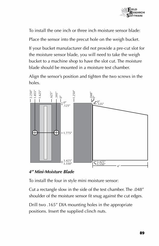
1” or 3” Moisture BladeThe one inch blade configuration is identical to the three-inch blade configuration, only with the outer two inches of the blade cut off.
89
To install the one inch or three inch moisture sensor blade:
Place the sensor into the precut hole on the weigh bucket.
If your bucket manufacturer did not provide a pre-cut slot for the moisture sensor blade, you will need to take the weigh bucket to a machine shop to have the slot cut. The moisture blade should be mounted in a moisture test chamber.
Align the sensor’s position and tighten the two screws in the holes.
0”
0”
3.550”
.125”
4”3.425”
.048
”
1.25
0”
1.775”
2.25
0”1.
855”
0”
3.550”
.625
”
.395
”
3.425”
.125”0”
1.62
5”
4” Mini-Moisture Blade
To install the four in style mini moisture sensor:
Cut a rectangle slow in the side of the test chamber. The .048” shoulder of the moisture sensor fit snug against the cut edges.
Drill two .165” DIA mounting holes in the appropriate positions. Insert the supplied clinch nuts.

90
A p p e n d i x
A basic Test-Harvest System. This installation includes a test-chamber load cell as well as a plot-weight load cell; therefore, the assembly includes a test chamber. A moisture sensor is installed in the test chamber in this example.
Holding Hopper
Actuator
Limit Switches
Plot Weight Load Cell
Test Weight Load Cell
Plot Weight Bucket
Test Weight Bucket
Moisture Blade
Actuator
Limit Switches
Actuator
Limit Switches

91

92
A p p e n d i x
A p p e n d i x C
C a b l e w i r i n g d i a g r a m s
f o r t h e H M - 4 0 1
The Harvest Data System ConsoleSensor Control and Conditiong Unit (SCCU)
To RS-485 Port
Allegro charge cable
Charge Port of Allegro
Console Base
To Allegro COM 1
Allegro F/PC cradle mount here
Field Printer
WeightBottom
Mid Top
Figure C-2: Cables connecting SCCU
The Allegro and Harvest Data System Field Printer fit into the Harvest Data System console base.
The Field Printer is an optional component for convenient field use.

93
Power Cable Connection
To connect the power cable, complete the following steps:
1. Attach the pigtail end of the power cable to the combine battery (12V power supply). It is recommended to connect the negative side of the power cable to the end of the ground cable furthest away from the battery (connected to the chassis—refer to figure on the next page). If your system is equipped with a lockout system, this eliminates any potential problems.
2. Plug the power supply cable into the SCCU, and twist the locking ring to secure the connector to the SCCU.
3. If you haven’t done so already, attach the Allegro DC power plug to the Allegro’s charge port.
You need to make sure the polarity of the positive and negative battery terminal are wired correctly. Reversing the polarity could cause possible hardware damage. Also, the 12V power supply wire is red or white (+). The ground wire is black (–).
SCCUPower Cable(Model # CA-HM-335)
Combine Battery
Chassis
System Control Cable (Model # CA-HM-420)
37 Pin Connector
HM-420 BF Breakout Box
Figure:C-4: Cable Connectors for the SCCU.

94
A p p e n d i x
HM-420 37-pin System Control CableIn a standard system control cable there are: Four pairs of shielded cables
Four pairs of shielded cables,
Four 20 AWG twisted pairs,
Nine 24 AWG single wires,
Three 22 AWG twisted pairs,
Two 22 AWG single wires,
Four 24 AWG single drain wires for the shielded twisted pairs.
24 AWG single drain wire (gnd)
24 AWG single wire
20 AWG twisted pair
Shielded twisted pair (SH)
22 AWG twisted pair
22 AWG single wire
•
•
•
•
•
•
95
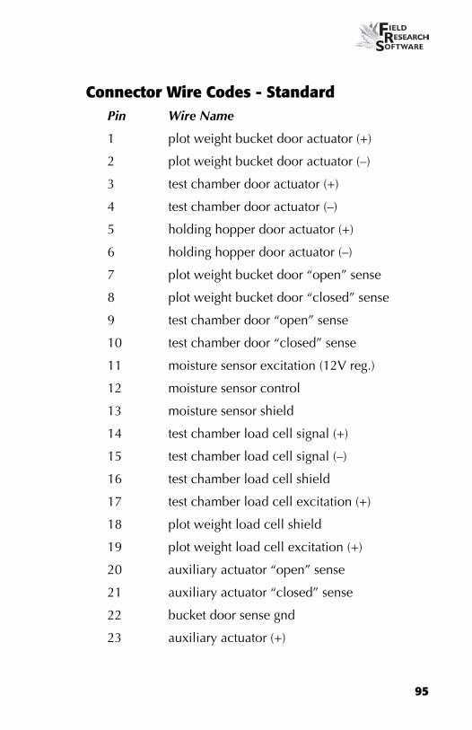
Connector Wire Codes - StandardPin Wire Name
1 plot weight bucket door actuator (+)
2 plot weight bucket door actuator (–)
3 test chamber door actuator (+)
4 test chamber door actuator (–)
5 holding hopper door actuator (+)
6 holding hopper door actuator (–)
7 plot weight bucket door “open” sense
8 plot weight bucket door “closed” sense
9 test chamber door “open” sense
10 test chamber door “closed” sense
11 moisture sensor excitation (12V reg.)
12 moisture sensor control
13 moisture sensor shield
14 test chamber load cell signal (+)
15 test chamber load cell signal (–)
16 test chamber load cell shield
17 test chamber load cell excitation (+)
18 plot weight load cell shield
19 plot weight load cell excitation (+)
20 auxiliary actuator “open” sense
21 auxiliary actuator “closed” sense
22 bucket door sense gnd
23 auxiliary actuator (+)
96
A p p e n d i x
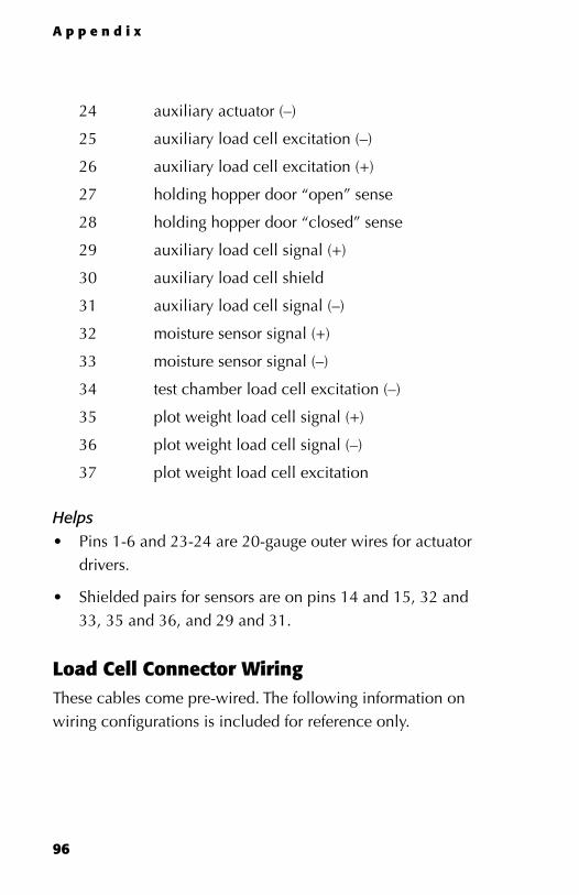
24 auxiliary actuator (–)
25 auxiliary load cell excitation (–)
26 auxiliary load cell excitation (+)
27 holding hopper door “open” sense
28 holding hopper door “closed” sense
29 auxiliary load cell signal (+)
30 auxiliary load cell shield
31 auxiliary load cell signal (–)
32 moisture sensor signal (+)
33 moisture sensor signal (–)
34 test chamber load cell excitation (–)
35 plot weight load cell signal (+)
36 plot weight load cell signal (–)
37 plot weight load cell excitation
HelpsPins 1-6 and 23-24 are 20-gauge outer wires for actuator drivers.
Shielded pairs for sensors are on pins 14 and 15, 32 and 33, 35 and 36, and 29 and 31.
Load Cell Connector WiringThese cables come pre-wired. The following information on wiring configurations is included for reference only.
•
•
97
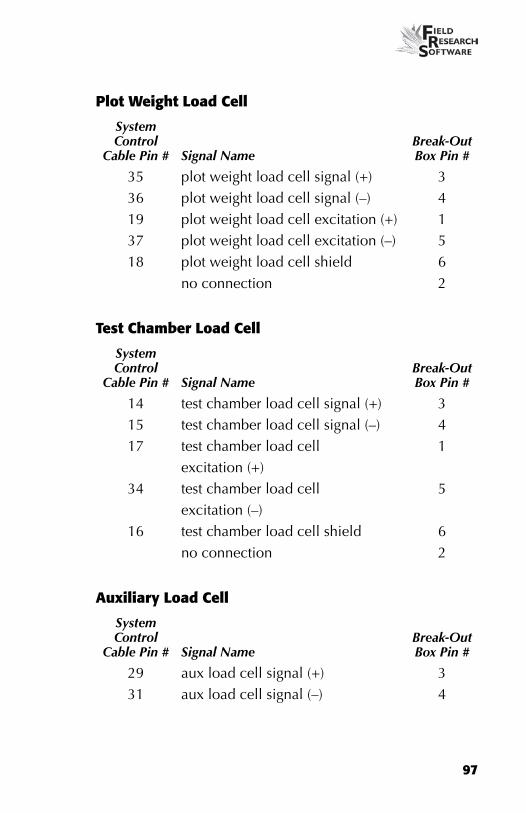
Plot Weight Load Cell
System Control
Cable Pin # Signal NameBreak-Out Box Pin #
35 plot weight load cell signal (+) 336 plot weight load cell signal (–) 419 plot weight load cell excitation (+) 137 plot weight load cell excitation (–) 518 plot weight load cell shield 6
no connection 2
Test Chamber Load Cell
System Control
Cable Pin # Signal NameBreak-Out Box Pin #
14 test chamber load cell signal (+) 315 test chamber load cell signal (–) 417 test chamber load cell
excitation (+)1
34 test chamber load cell excitation (–)
5
16 test chamber load cell shield 6no connection 2
Auxiliary Load Cell
System Control
Cable Pin # Signal NameBreak-Out Box Pin #
29 aux load cell signal (+) 331 aux load cell signal (–) 4
98
A p p e n d i x
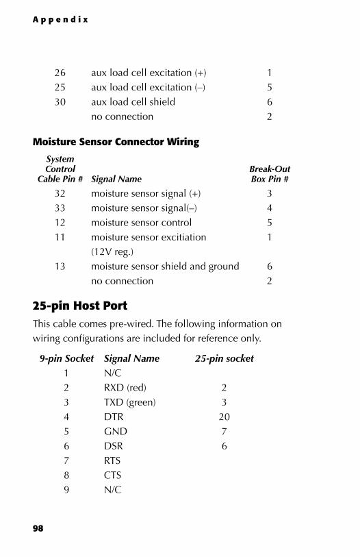
26 aux load cell excitation (+) 125 aux load cell excitation (–) 530 aux load cell shield 6
no connection 2
Moisture Sensor Connector Wiring
System Control
Cable Pin # Signal NameBreak-Out Box Pin #
32 moisture sensor signal (+) 333 moisture sensor signal(–) 412 moisture sensor control 511 moisture sensor excitiation
(12V reg.)1
13 moisture sensor shield and ground 6no connection 2
25-pin Host PortThis cable comes pre-wired. The following information on wiring configurations are included for reference only.
9-pin Socket Signal Name 25-pin socket1 N/C2 RXD (red) 23 TXD (green) 34 DTR 205 GND 76 DSR 67 RTS8 CTS9 N/C
99
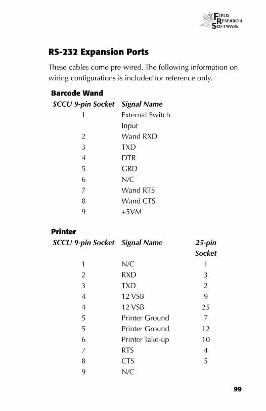
RS-232 Expansion Ports
These cables come pre-wired. The following information on wiring configurations is included for reference only.
barcode WandSCCU 9-pin Socket Signal Name
1 external Switch Input
2 Wand RXD3 TXD4 DTR5 GRD6 N/C7 Wand RTS8 Wand CTS9 +5VM
PrinterSCCU 9-pin Socket Signal Name 25-pin
Socket1 N/C 12 RXD 33 TXD 24 12 VSB 94 12 VSB 255 Printer Ground 75 Printer Ground 126 Printer Take-up 107 RTS 48 CTS 59 N/C

100
A p p e n d i x
HvDSCCU 9-pin Socket Signal Name
1 N/C2 RXD3 TXD4 +12 VBSP5 Ground6 N/C7 N/C8 CTS9 +5VM
RS-485SCCU 9-pin Socket Signal Name
1 N/C2 RS485 Low3 RS 485 High4 +12 VBSP5 Ground6 N/C7 N/C8 N/C9 N/C

101

102
A p p e n d i x
A p p e n d i x D
C a b l e W i r i n g D i a g r a m s
f o r t h e H M - 8 0 0
Cable Connections for HM-800Within the HM-800 there are several components. Figure D-1 shows the components wired on the stand.
Figure D-1: Front view of HM-800 components
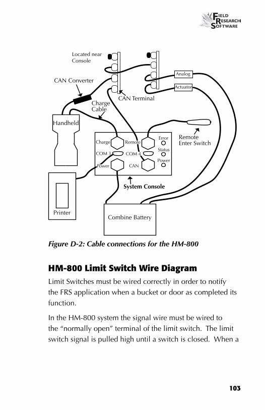
Figure D-2 shows the cable connections from the HM-800 System Console and modules to other components.
103
System Console
CAN Terminal
Handheld
Charge Cable
Printer
CAN Converter
Remote enter Switch
Combine Battery
COM 3
Charge
CAN
error
Status
Power
Remote
COM 4
Power
Actuator
Analog
Located near Console
Figure D-2: Cable connections for the HM-800
HM-800 Limit Switch Wire DiagramLimit Switches must be wired correctly in order to notify the FRS application when a bucket or door as completed its function.
In the HM-800 system the signal wire must be wired to the “normally open” terminal of the limit switch. The limit switch signal is pulled high until a switch is closed. When a
104
A p p e n d i x
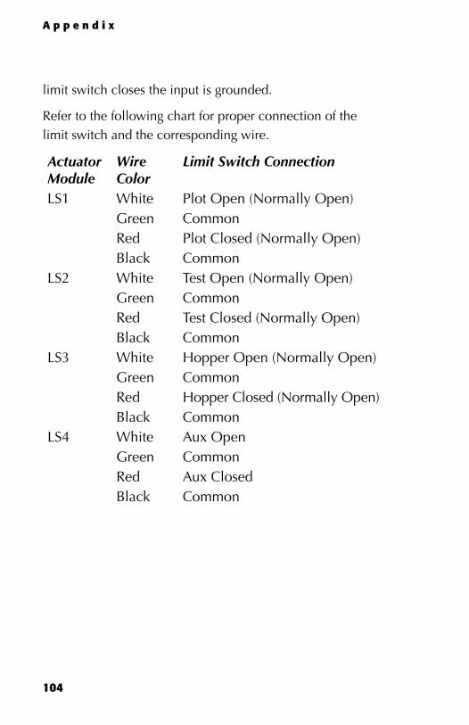
limit switch closes the input is grounded.
Refer to the following chart for proper connection of the limit switch and the corresponding wire.
Actuator Module
Wire Color
Limit Switch Connection
LS1 White Plot Open (Normally Open)Green CommonRed Plot Closed (Normally Open)Black Common
LS2 White Test Open (Normally Open)Green CommonRed Test Closed (Normally Open)Black Common
LS3 White Hopper Open (Normally Open)Green CommonRed Hopper Closed (Normally Open)Black Common
LS4 White Aux OpenGreen CommonRed Aux ClosedBlack Common

105
For all Pnuematic, Electric, and Hydralic ActuatorsActuator Connection Red Bucket Open
Black Bucket Close
Windshield WiperActuator Connectionn Red Low Terminal
Black Park Terminal
106
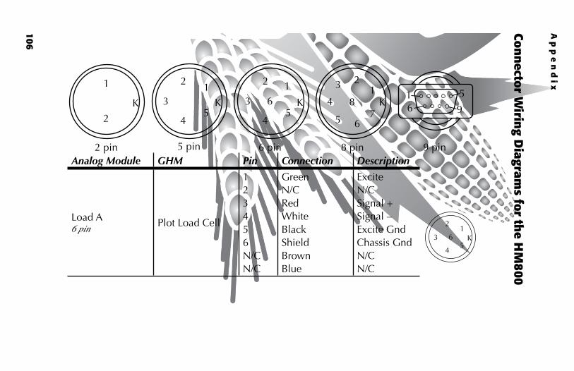
Analog Module GHM Pin Connection Description
Load A 6 pin
Plot Load Cell
123456N/CN/C
GreenN/CRedWhiteBlackShieldBrownBlue
exciteN/CSignal +Signal –excite GndChassis GndN/CN/C
Conn
ector Wirin
g Diagram
s for the H
M800
8 pin
K1
23
4
5 67
8
6 pin
12
3
45
6 K
5 pin
K1
2
3
45
2 pin
K
1
2
9 pin
1 56 9
12
3
45
6 K
Ap
pe
nd
ix

107
Analog Module GHM Pin Connection Description
Load B 6 pin
Test Load Cell
123456N/CN/C
GreenN/CRedWhiteBlackShieldBrownBlue
exciteN/CSignal +Signal –excite GndChassis GndN/CN/C
Load C 6 pin
Load Cell (Third load cell in multiple load cell applications)
123456N/CN/C
GreenN/CRedWhiteBlackShieldBrownBlue
exciteN/CSignal +Signal –excite GndChassis GndN/CN/C
12
3
45
6 K
12
3
45
6 K

108
Ap
pe
nd
ix
Analog Module GHM Pin Connection Description
Load D 6 pin
123456N/CN/C
GreenN/CRedWhiteBlackShieldBrownBlue
exciteN/CSignal +Signal –excite GndChassis GndN/CN/C
CAN 8 pin
12345678
RedYellowBlackGreenN/CN/CN/CN/C
CAN PowerCAN +CAN GndCAN –N/CN/CN/CN/C
12
3
45
6 K
K1
234
5 67
8

109
Analog Module GHM Pin Connection Description
CAN-DIAG 8 pin
CAN
12345678
RedYellowBlackGreenN/CN/CN/CN/C
CAN PowerCAN +CAN GndCAN –N/CN/CN/CN/C
Moisture 5 pin
Moisture eM Sens
12345
RedBlackGreenWhiteShield
exciteGroundSignal +Signal –Ground
Power 2 pin
Power12
BlackRed
Ground+12 V
K
1
2
K1
2
3
45
K1
234
5 67
8
110
Ap
pe
nd
ix
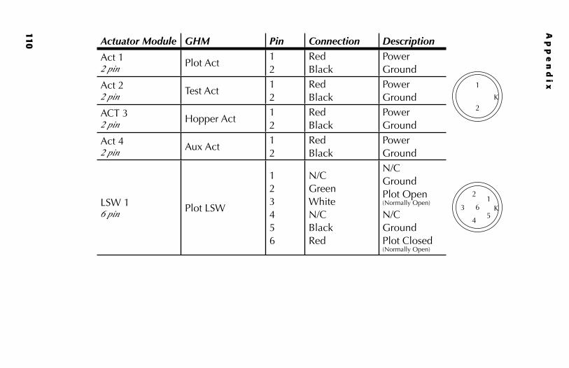
Actuator Module GHM Pin Connection Description
Act 1 2 pin
Plot Act12
RedBlack
PowerGround
Act 2 2 pin
Test Act12
RedBlack
PowerGround
ACT 3 2 pin
Hopper Act12
RedBlack
PowerGround
Act 4 2 pin
Aux Act12
RedBlack
PowerGround
LSW 1 6 pin
Plot LSW
123456
N/CGreenWhiteN/CBlackRed
N/CGroundPlot Open (Normally Open)
N/CGroundPlot Closed (Normally Open)
K
1
2
12
3
45
6 K

111
Actuator Module GHM Pin Connection Description
LSW 2 6 pin
Test LSW
123456
N/CGreenWhiteN/CBlackRed
N/CGroundTest Open (Normally Open)
N/CGroundTest Closed (Normally Open)
LSW 3 6 pin
Hopper LSW
123456
N/CGreenWhiteN/CBlackRed
N/CGroundHopper Open (Normally Open)
N/CGroundHopper Closed (Normally Open)
12
3
45
6 K
12
3
45
6 K

112
Ap
pe
nd
ix
Actuator Module GHM Pin Connection Description
LSW 4 6 pin
N/A
123456
N/CGreenWhiteN/CBlackRed
N/CGroundAux OpenN/CGroundAux Open
CAN 8 pin
CAN (patch Cable)
12345678
RedYellowBlackGreenN/CN/CN/CN/C
CAN PowerCAN +CAN GndCAN –N/CN/CN/CN/C
Power 2 pin
Power12
BlackRed
Ground+12 V K
1
2
K1
234
5 67
8
12
3
45
6 K
113
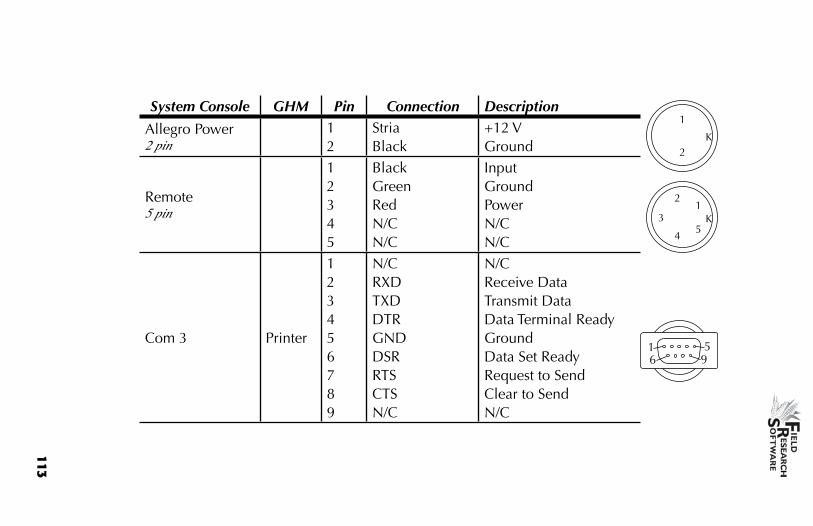
System Console GHM Pin Connection Description
Allegro Power 2 pin
12
StriaBlack
+12 VGround
Remote 5 pin
12345
BlackGreenRedN/CN/C
InputGroundPowerN/CN/C
Com 3 Printer
123456789
N/CRXDTXDDTRGNDDSRRTSCTSN/C
N/CReceive DataTransmit DataData Terminal ReadyGroundData Set ReadyRequest to SendClear to SendN/C
K1
2
3
45
1 56 9
K
1
2
114
Ap
pe
nd
ix
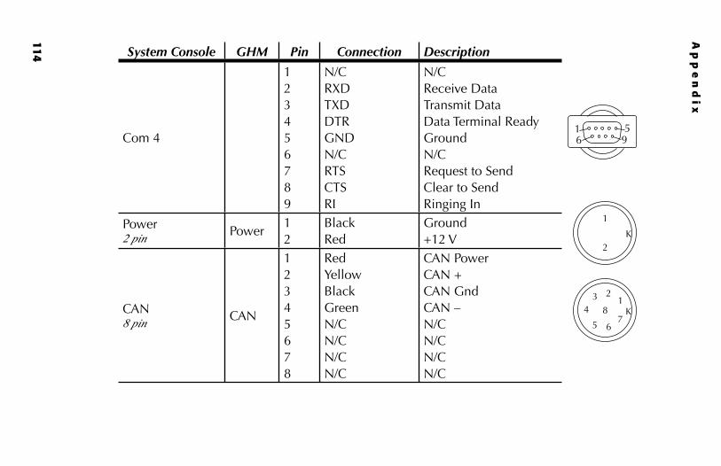
System Console GHM Pin Connection Description
Com 4
123456789
N/CRXDTXDDTRGNDN/CRTSCTSRI
N/CReceive DataTransmit DataData Terminal ReadyGroundN/CRequest to SendClear to SendRinging In
Power 2 pin
Power12
BlackRed
Ground+12 V
CAN 8 pin
CAN
12345678
RedYellowBlackGreenN/CN/CN/CN/C
CAN PowerCAN +CAN GndCAN –N/CN/CN/CN/C
K
1
2
K1
234
5 67
8
1 56 9

InDEx

116
I n d e x
37-pin system control cable 94
A
Actuator 110actuator 37, 48, 77
controls screen 48setup screen 37
Analog Module 106
C
cables 12, 7625-pin host port 982 pin 1065 pin 1066 pin 1068 pin 1069 pin 106power 93RS-232 expansion ports 99system control (HM-420) 94
cable wiring diagrams 92calibrate 76
accuracy 43equations 31load cells 17, 21, 43manually adjusting load cell 18moisture 25temperature 29, 30, 31weight 16
117
D
dataActiveSync 72collection mode 61exporting screen 71
target path 72extracting 70field map 72prearing to collect 60viewing 67
diagnostics 42
E
emulation mode 14enable
Generic Harvest Module 12error codes 46
F
field mapextract 72new 61
field printer 92Field Research Software. See FRSFRS
Note Taking 9
G
Generic Harvest Module 8, 90collecting data 60enable 12holding hopper function 22maintenance 76preparing for harvest 16
GHM config screen 33

118
H
harvestingdata. See data viewingnavigation type 63
circular navigation 63sequential navigation 63serpentine navigation 64
plot harvest 64route 63starting location 62, 64
harvest template. See traits template screenHM800
system console 102
I
import/export utility 71installing
FRS 9harvest data system 78
L
limit switch 38load cell 43
calibration 21checking calibration 43recalibrate 44
load cell screen 43
M
maintenance 78daily 76post-harvest 77pre-harvest 76
manage devices 13master traits list. See traits
I n d e x

119
moisture 33, 44, 53correction multiplier 29sensor 23, 88
error code 46interpretation of codes 47LED codes 46
temperature 30moisture curve 27, 31
adjusting 28, 30copying 33creating 27default 25default (graph) 26deleting 32editing 24
moisture screen 45, 46absolutre volts 45moisture 45relative volts 45select 46tare 45temperature 45
mounting diagrams 86field computer cradle 86printer 87system console 86
N
navigation type. See harvesting navigation type
O
operating pressure 77
P
pneumatics 77, 78print calibrations 49

120
R
repair 79retare 45Returned Materials Authorization (RMA) 79
S
SCCUcable wiring 92error 47
Sensor Control and Conditiong Unit. See SCCUsetup
two combines 38setup file 38
default 39setup menu 13single plot combine 63starting plot cell 62
T
tare 44test weight
chamber volume 34timers 35
countdown timer 37, 65hopper open 36plot open 36settle time 36setup screen 35weight time 36
traits 52adding 52creating 52, 53data source 54description 54master traits list screen 52template screen 55
traits management 55troubleshoot 42
I n d e x
121
V
volts 45
W
warrantydisclaimer 84extended 85hardware 82serial number 85software 83
Windows CE 8wiring
actuator 110analog 106barcode wand 99HVD 100load cell 96
auxiliary 97plot weight 97test chamber 97
printer 99RS-485 100standard wire codes 95system console 113