
Field monitoring of ozone precursor type and air toxic ... · HRVOC Component Identification 1....
28
Field monitoring of ozone precursor type and air toxic compounds with a small, fast GC analyzer: the microFAST GC Edward B. Overton ([email protected]), Scott Miles, Buffy Ashton, and Scott McDaniel LSU Dept of Environmental Sciences and Analytical Specialists Inc. (ASI)
Transcript of Field monitoring of ozone precursor type and air toxic ... · HRVOC Component Identification 1....

Field monitoring of ozone precursor type and air toxic
compounds with a small, fast GC analyzer: the microFAST GC
Edward B. Overton ([email protected]), Scott Miles, Buffy Ashton, and Scott McDaniel LSU Dept of Environmental Sciences and
Analytical Specialists Inc. (ASI)

Why HRVOC verses VOC Analysis?

Important VOCsEthane**Ethene*&**Propane**Propene*&**Butanes**Butenes*Pentane**Pentenes*Isoprene*&**Benzene**Toluene**Xylenes & Ethyl Benzene**
*biogenic sources ** geogenic and anthropogenic sources

EnvironmentalHRVOC Analysis
On-SiteOn-Site LaboratoryLaboratory
microFAST GC for HRVOCs
Temp, wind speed, RH TD-GC-TOF-MSand
LSU Analytical Scheme
Temp, wind speed, RH GC, GC-MS
Traditional analytical scheme

On Site Speciation
Larger number of analysesReal time feed-backNo sample lossless chance for contamination
Pros
Difficult to do speciationSlightly less sensitive
Lab Speciation
Slow analysisTarget compoundsPossible sample alteration
Traditional approachGood QA/QCControlled Environment(GC-TOF-MS full scanning)
Cons
HRVOCs are reactive compounds, can be loss in sample transport
•HRVOCs (olefins) have half lives measured in minutes and are important ozone precursors•VOCs (NMHC)are stable and less subjected to sample loss, also less important in ozone formation

TD-GCMS

microFAST GCAnalysis
GC Utilities

HRVOC Component IdentificationHRVOC Component Identification
1. Ethane2. Ethylene3. Propane4. Propylene5. Butane (2ppm)6. 1-butene7. 1,3-butadiene8. Pentane (2ppm)9. 1-pentene10. Isoprene11. Hexane (2ppm)12. 1-hexene13. Heptane14. Benzene15. Isooctane16. Octane17. Toluene18. Nonane19. Ethylbenzene20. m,p-Xylene21. o-Xylene
1. m,p-Xylene, nonane, ethylbenzene
2. o-Xylene3. 1,2,4-trimethylbenzene
1
5
2
8
364
7 1514
1312
11
109
1
2119
181716
20
23
GasPro
DB-5

microFAST Near-Shore Averages: 76 SamplesGrand Isle 8/20‐22/07
Cameron 9/5‐6/07
Port Fourchon 9/17/07
Port Fourchon 10/1‐4/07
Green Canyon 6/9/08
Analyte Site Avg Conc (ppbv) Site Avg Conc (ppbv) Site Avg Conc (ppbv) Site Avg Conc (ppbv) Site Avg Conc (ppbv)
Ethane 1.1 1.1 0.7 0.1 0.0
Ethylene 8.5 2.2 2.4 0.0 0.0
Propane 2.3 0.4 0.2 0.0 0.0
Propylene 0.6 0.0 0.4 0.0 0.0
Butane 1.5 0.3 11 0.0 0.0
1‐Butene 0.4 0.0 6.5 0.0 0.0
Pentane 0.4 0.0 0.0 0.0 0.0
1‐Pentene 2.0 0.7 0.0 0.0 0.0
Hexane/Isoprene 2.2 0.1 7.7 0.0 10
1‐Hexene 0.0 0.0 0.0 0.0 0.0
Benzene 0.2 0.1 0.1 1.0 7.2
Toluene 0.1 0.1 0.1 1.0 16
Xylenes 0.1 0.1 0.1 0.8 8.4

microFAST
GC set‐up at Green Canyon Site
Dual microFAST GC instruments operating on the aft deckin the Green Canyon sampling area


50L H Bank
Hydrogen Storage Cylinderdelivery pressure of ~50 psi
0.5 liter H2 high pressureStorage Cylinder(1500 psi)with required regulator~ 50 L of Hydrogen
for microFAST GC PortaPack

HRVOC Installation

Soil Gas Sampling and Analysis
In15 minutes
or less


The microFAST GC rapidly analyzes compounds using:
• two short, narrow bore capillary columns (1 -3 meters)•ultra fast temperature programming (5-25°C/sec)•high velocity hydrogen carrier gas flows with FIDs•rapid injection via desorption from a focusing micro trap
The sophisticated sequence of method-driven events that enable the wide dynamic range of microFAST GC analyses includes the following steps:•Sampling of air, liquid extracts, SPME, or aqueous solutions•Purging the trap and injector of residual air or solvent •Equilibrating the pressure within the injector and trap zones to the pressure at the head of the columns•Rapidly heating the trap under no flow conditions•Transferring thermally desorbed analytes from the trap to the head of the columns in a narrow plug•Rapid temperature programming the separation columns and detecting eluting compounds•Cleaning out of the trap simultaneously with the chromatographic separation process•Cooling down the columns and trap in preparation for the next analysis


Pneumatic Manifold
Injection Trap & Heater
flow�restrictor
external purge
Injector vent
vacuum pump vent
hydrogen @ 40psi
Ballast vent
dual columns and heater assembly
FID Air
Back Panel
FID Vents
Ballast
PF1
carrier flow
Heated Sample Inlet
septa
removable glass liner
PF2
PF3
FID fuel
heated zone (det. heater)
V3
V5V1
V8
electronic pressure regulators
cooling fan V6
V4 (n open)
splitterInjector Heater
FID Manifold
finger tight
connections
column compartment
sheath
head of columns
end of columns
Vacumn Pump
cooling fan V7
blocked off

ultra fast temperature
programming up to 25°C/second
Low Thermal MassHeater & 2 Cap Columns
column heater
columns�oven�
sheath�~1mm ID
microFAST GC analytical columns
assembly
column #1 100 micron ID
DB-5
column #2column #2
100 micron ID DB-1701
column heater sheath
Column Types: ·100 to 320 micron ID ·1 to 3 meters in length ·either open tubular or PLOT

0
50
100
150
200
250
300
20 50 80 110 140 170
time (s)
5 °C/sec
0
50
100
150
200
250
300
0 20 40 60 80 100 120time (s)
15°C/sec
microFAST™ GC’sColumn TemperatureVersesHeating Rates

• flash evaporative injectors • sample loops • solid sorbent traps • Solid Phase Micro Extractions (SPME)
neat liquids, organic solvent extracts of liquid and solid samples
permanent gases gases under high pressure
dilute gases, Industrial Hygiene Samples Purge and Trap VOCs, Static/Dymanic Headspace VOCs
primarily VOCs in liquid and head-space samples
• microFAST GC's flash evaporative solid sorbent trap injection system
all of the above, plus SCF and pyrolysis extracts and direct aqueous samples
GC Inlet Systems

Sample Valve forContinuous Samplingof VOCs/HRVOCs
Trap &heater
from injector
Sorbent Trap Based Injector
Trap & heater
Septa cap
Pneumatic Manifold
Injection Trap
flow�restrictor
Injector vent
vacuum pump vent
hydrogen @ 40psi
dual columns and heater assembly
FID Air
Back Panel
FID Vents
Ballast
PF1
carrier flow
septa
removable glass liner
PF2
PF3
FID fuel
heated zone (det. heater)
V3
V5 V1
V8
electronic pressure regulators
splitter
FID Manifold
finger tight
connections
column compartment
sheath
head of columns
end of columns
Vacuum Pump
blocked offBreath Sampler
teflon sampling
valve

0 1 2 3 4 5 6 7 8 9 10 11 12 13 14 15 16 17 18 19 20 21 22 23+
Carbon Number Range (RI =Carbon # times 100)
Permanent Gases
VOCs
SemiVOCs
>250mmVP
250 to 0.1mm VP
0.1 to .000001mmVP
GC Dynamic Ranges
micropacked GC column,
loop injectorthick film capillary
sorbent trap injector thin film capillary sorbent trap or flash heated injector
% to ppm
ppm to high ppb
low ppm to low ppb
HBV-challenging
HBV-straight-forward
Human Breath Volatile(HBV) Analyses
Dr. Phillips’ Analytes
Pneumatic Manifold
Injection Trap
flow�restrictor
Injector vent
vacuum pump vent
hydrogen @ 40psi
dual columns and heater assembly
FID Air
Back Panel
FID Vents
Ballast
PF1
carrier flow
septa
removable glass liner
PF2
PF3
FID fuel
heated zone (det. heater)
V3
V5 V1
V8
electronic pressure regulators
splitter
FID Manifold
finger tight
connections
column compartment
sheath
head of columns
end of columns
Vacuum Pump
blocked offBreath Sampler
teflon sampling
valve
Pneumatic Manifold
Injection Trap & Heater
flow�restrictor
external purge
Injector vent
vacuum pump vent
hydrogen @ 40psi
Ballast vent
dual columns and heater assembly
FID Air
Back Panel
FID Vents
Ballast
PF1
carrier flow
teflon septa plug
removable glass liner
sorbent trap
PF2
PF3
FID fuel
heated zone (det. heater)
V3
V5V1
V8
electronic pressure regulators
cooling fan V6
V4 (n open)
splitter
FID Manifold
finger tight
connections
column compartment
sheath
head of columns
end of columns
Vacuum Pump
cooling fan V7
blocked off
Flow PathFlow Direction
septa cap
sorbent material
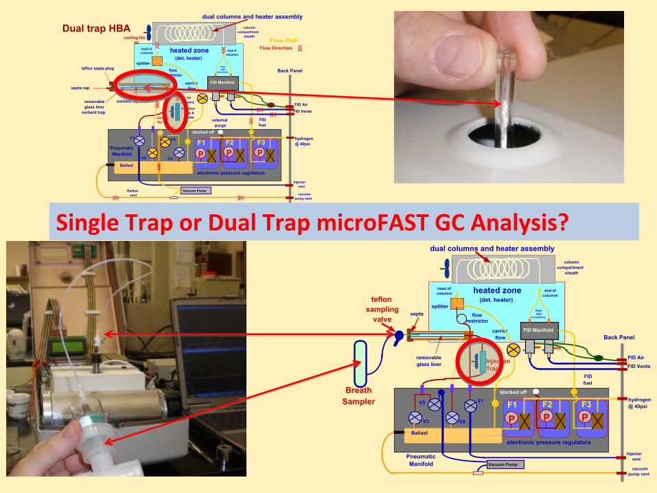
Dual trap HBA
Single Trap or Dual Trap microFAST GC Analysis?

Pneumatic Manifold
Injection Trap & Heater
flow�restrictor
external purge
Injector vent
vacuum pump vent
hydrogen @ 40psi
Ballast vent
dual columns and heater assembly
FID Air
Back Panel
FID Vents
Ballast
PF1
carrier flow
teflon septa plug
removable glass liner
sorbent trap
PF2
PF3
FID fuel
heated zone (det. heater)
V3
V5V1
V8
electronic pressure regulators
cooling fan V6
V4 (n open)
splitter
FID Manifold
finger tight
connections
column compartment
sheath
head of columns
end of columns
Vacuum Pump
cooling fan V7
blocked off
Flow PathFlow Direction
septa cap
sorbent material
Dual trap HBA
Diagram of microFAST GCas a dual trap, dual column
Air Analyzer
trap1
trap2
Placing Trap #1 in MFGC

Dual‐Bed Sampling Trap
Bed 1‐Tenax GR
Bed 2‐Carboxen
Connection to vacuum pump
Connection to Tee Sampler
Dual bed traps sample a broader range of
compound volatilities than can be sampled using
a single bed trap, but dual bed traps are also
easier to contaminate than single bed traps
Step 1: collect breath sample on sampling trap

Place sorbent trap into the heated injection port of the microFAST GC
Step 2: place sampling trap into heated
injection port of the microFAST GC

Run analytes desorbed from
sampling trap using the microFAST
GC, with cycle times of 5 minutes
per analysis and with fast, dual
column GC separations of Breath
Volatiles
Step 4
DB‐5 Column
DB‐1701 Column


![· @e] fid\ XelXc](https://static.fdocuments.in/doc/165x107/5c04b62e09d3f2183a8c24fe/-e-fid-xelxc-.jpg)