Field Modification of DCU Support Skirt-to-Vessel...
37
Field Modification of DCU Support Skirt-to-Vessel Attachment Weld Geometry By: Pedro E. Amador – VP Business Development & Technology Darren Barborak PhD. – Director of Materials & Welding Patrick Lester BSWE CWI – Senior Welding Engineer
Transcript of Field Modification of DCU Support Skirt-to-Vessel...

Field Modification of DCU Support Skirt-to-Vessel
Attachment Weld Geometry
By: Pedro E. Amador – VP Business Development & TechnologyDarren Barborak PhD. – Director of Materials & WeldingPatrick Lester BSWE CWI – Senior Welding Engineer

Typical DCU Vessel Failure Modes
• Coker Vessels are known to be susceptible to low cycle fatigue damage
• Delayed Coking requires cyclic operation and the cyclic changes in temperature cause significant stress intensities
• Over time, as operating cycles accumulate, vessels start to experience a variety of failure modes
?
2
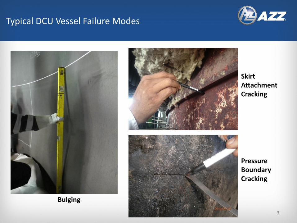
Typical DCU Vessel Failure Modes
Bulging
Skirt Attachment Cracking
Pressure Boundary Cracking
3

4
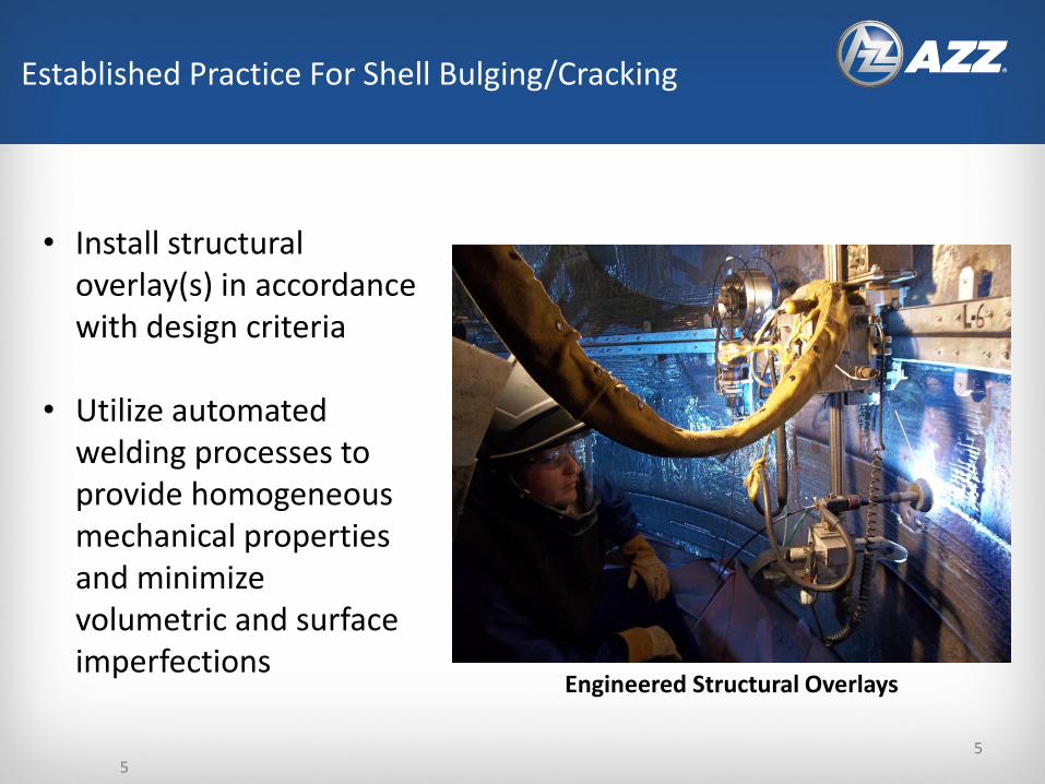
Established Practice For Shell Bulging/Cracking
Engineered Structural Overlays
• Map vessel to collect deformation data
• Evaluate stress/strain intensities with analytical tools
• Characterize highly affected areas
• Design “Structural Overlays” to address critical regions
4
5
Inco 625
Engineered Structural Overlays
Established Practice For Shell Bulging/Cracking
• Install structural overlay(s) in accordance with design criteria
• Utilize automated welding processes to provide homogeneous mechanical properties and minimize volumetric and surface imperfections
5
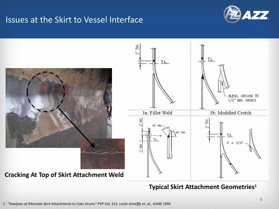
Typical Skirt Attachment Geometries1
Issues at the Skirt to Vessel Interface
1 - “Analyses of Alternate Skirt Attachments to Coke Drums” PVP Vol. 315, Leslie Antalffy et. al., ASME 1995
Cracking At Top of Skirt Attachment Weld
6
Field Attachment Weld Geometry Modification
Unique Implementation Case Study
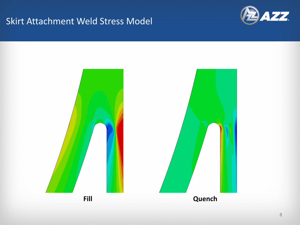
Skirt Attachment Weld Stress Model
Fill Quench
8
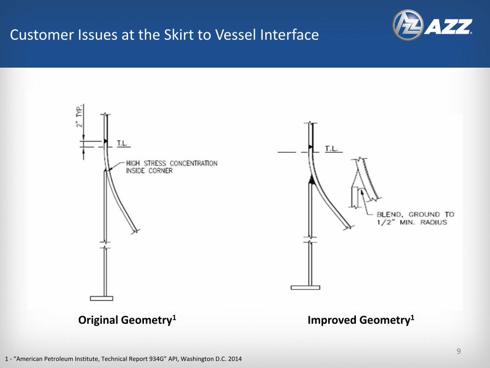
Customer Issues at the Skirt to Vessel Interface
Original Geometry1
1 - “American Petroleum Institute, Technical Report 934G” API, Washington D.C. 2014
Improved Geometry1
9

• Remove portions of the existing skirt using track mounted torch cutting system
• Remove remaining skirt to vessel connection weld metal and grind flush
• Repair performed in segments around the vessel to avoid need for crane support
Step 1 – Original Skirt Removal
10
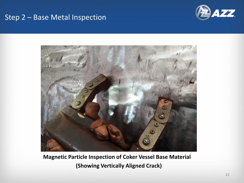
Magnetic Particle Inspection of Coker Vessel Base Material
(Showing Vertically Aligned Crack)
Step 2 – Base Metal Inspection
11
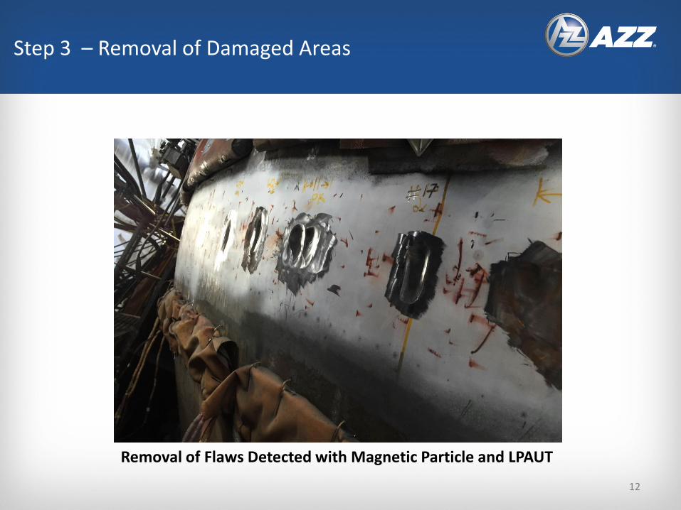
Removal of Flaws Detected with Magnetic Particle and LPAUT
Step 3 – Removal of Damaged Areas
12

13
Step 4 – Base Material Repair Welding
• The 2-1/4 Cr Cone Base material repaired/restored to nominal using NBIC Alternative Welding Method 2 repair (Temper Bead)
• 2-1/4 Cr filler materialER80S-B3L
• After welding, the surface of the cone was ground flush
13
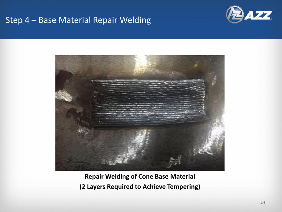
Repair Welding of Cone Base Material
(2 Layers Required to Achieve Tempering)
Step 4 – Base Material Repair Welding
14
15
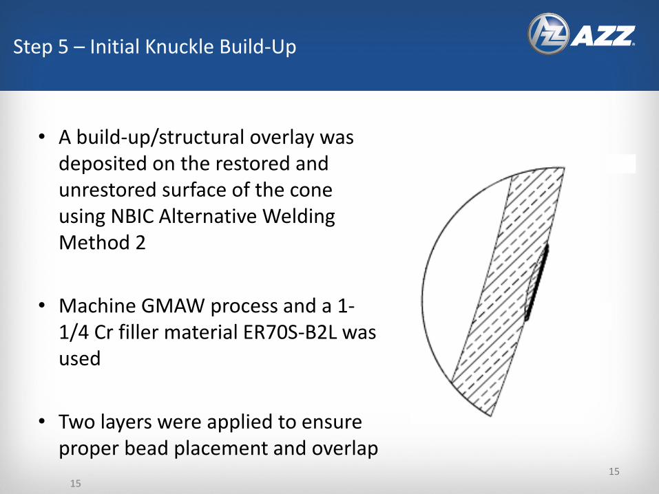
Step 5 – Initial Knuckle Build-Up
• A build-up/structural overlay was deposited on the restored and unrestored surface of the cone using NBIC Alternative Welding Method 2
• Machine GMAW process and a 1-1/4 Cr filler material ER70S-B2L was used
• Two layers were applied to ensure proper bead placement and overlap
15
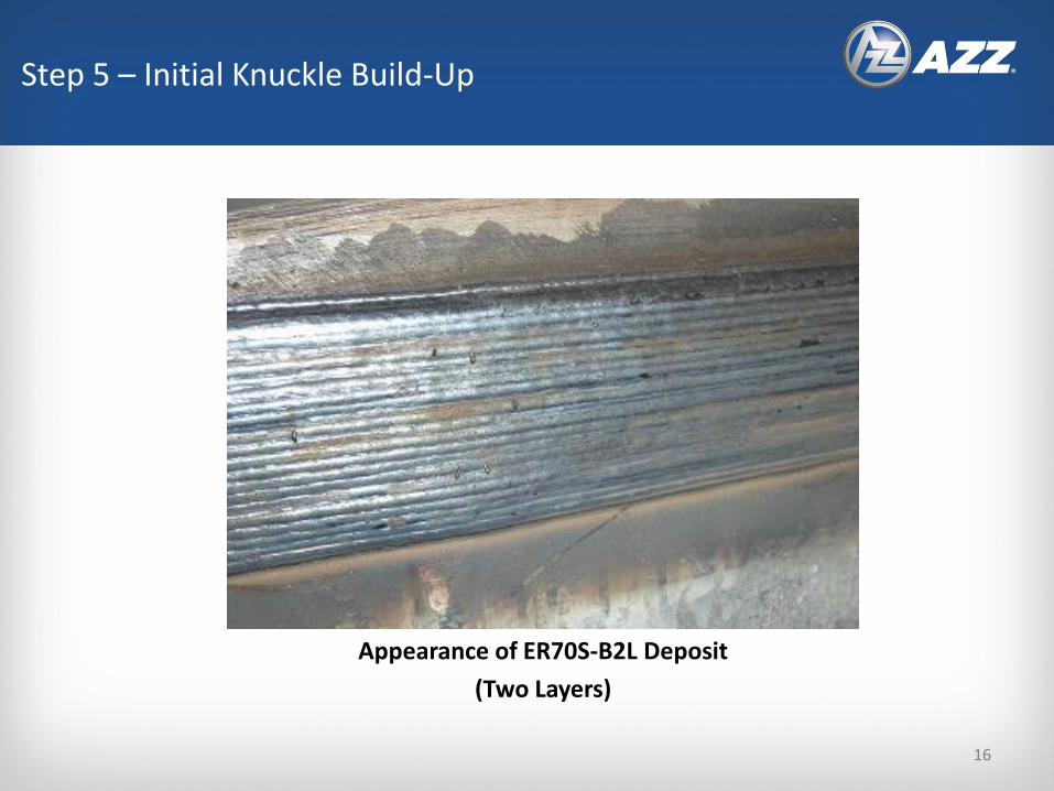
Appearance of ER70S-B2L Deposit
(Two Layers)
Step 5 – Initial Knuckle Build-Up
16
17
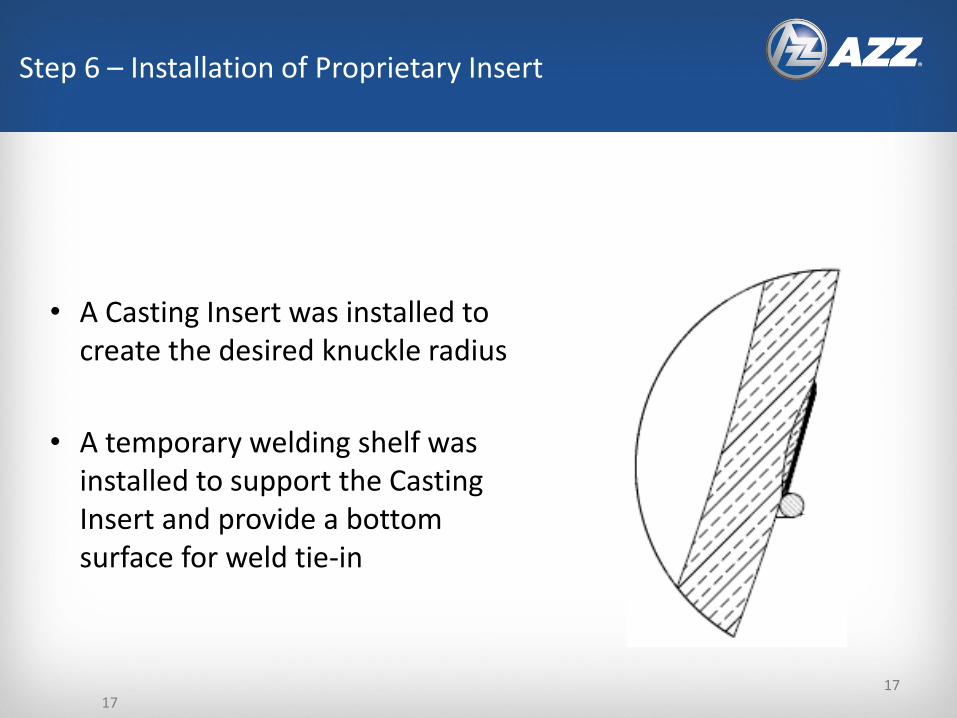
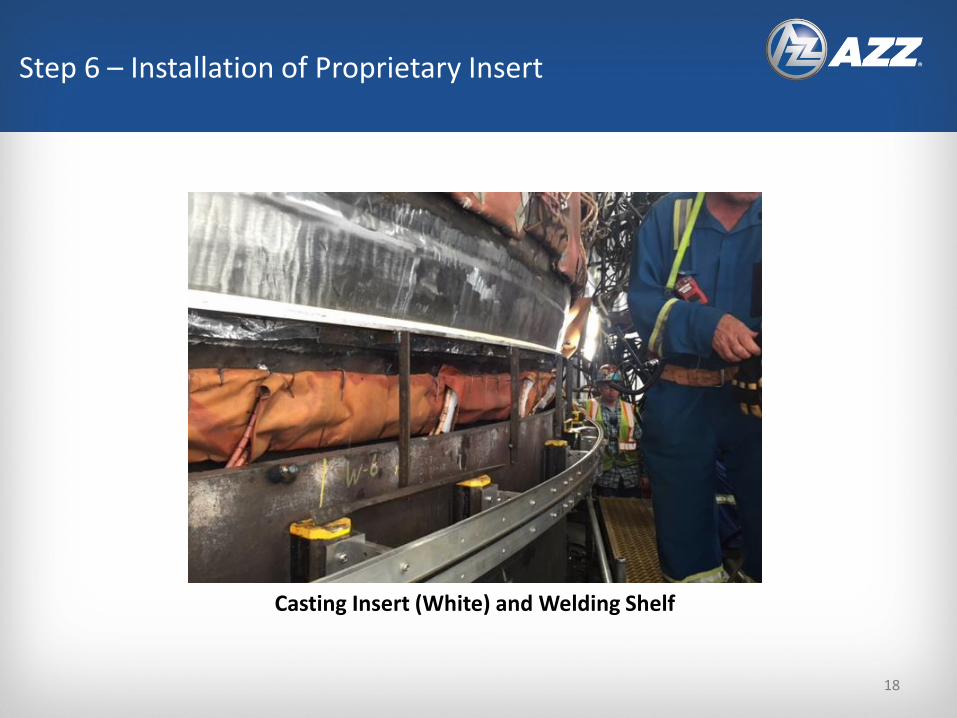
• A Casting Insert was installed to create the desired knuckle radius
• A temporary welding shelf was installed to support the Casting Insert and provide a bottom surface for weld tie-in
Step 6 – Installation of Proprietary Insert
17
Step 6 – Installation of Proprietary Insert
Casting Insert (White) and Welding Shelf
18
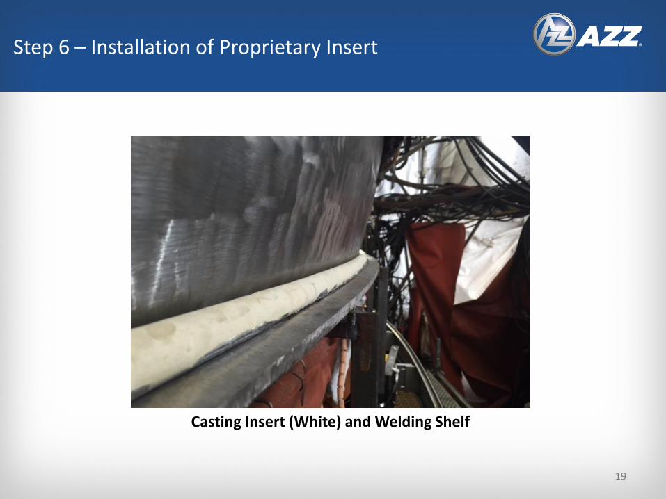
Casting Insert (White) and Welding Shelf
Step 6 – Installation of Proprietary Insert
19
20
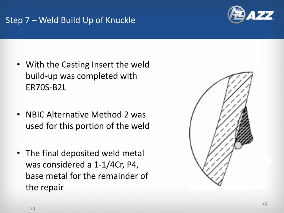
• With the Casting Insert the weld build-up was completed with ER70S-B2L
• NBIC Alternative Method 2 was used for this portion of the weld
• The final deposited weld metal was considered a 1-1/4Cr, P4, base metal for the remainder of the repair
Step 7 – Weld Build Up of Knuckle
20

Machine Applied Knuckle Weld Deposit
Completely Covering Casting Insert
Step 7 – Weld Build Up of Knuckle
21
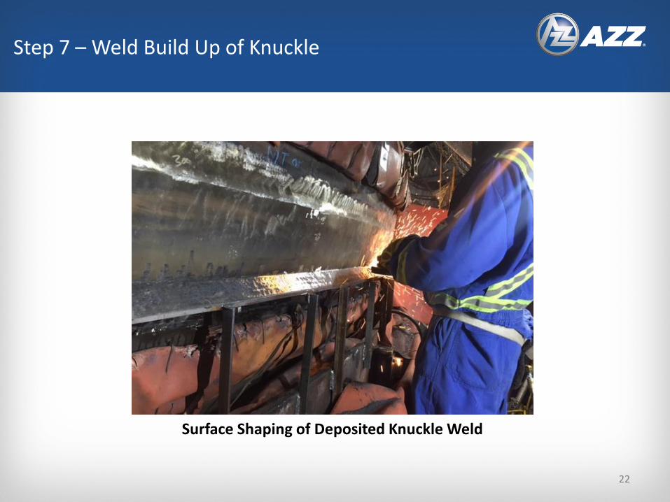
Surface Shaping of Deposited Knuckle Weld
Step 7 – Weld Build Up of Knuckle
22
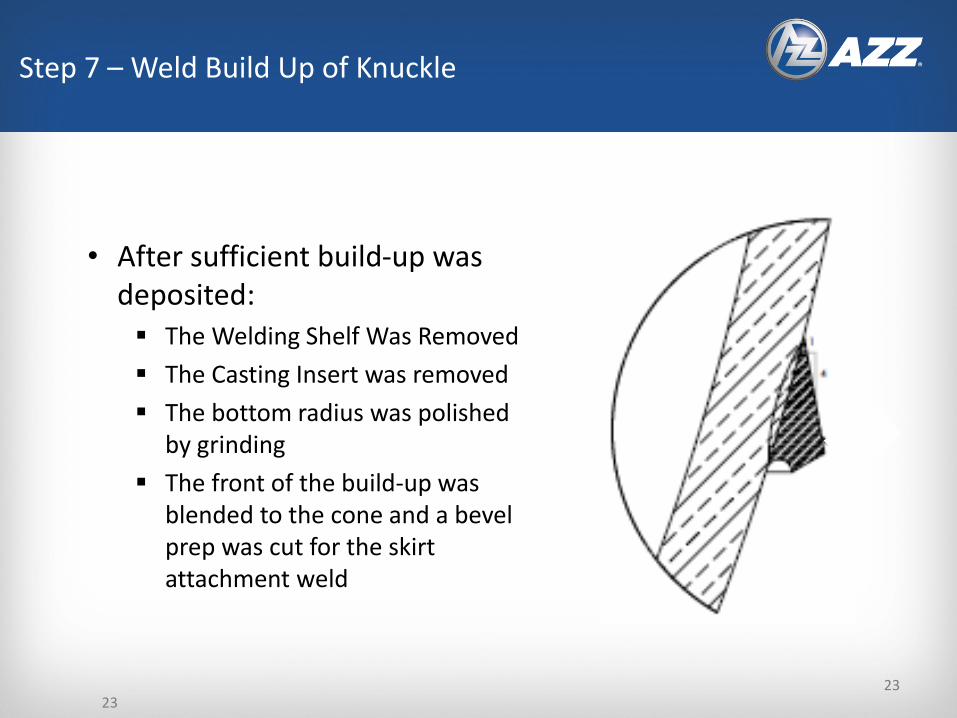
23
• After sufficient build-up was deposited:▪ The Welding Shelf Was Removed
▪ The Casting Insert was removed
▪ The bottom radius was polished by grinding
▪ The front of the build-up was blended to the cone and a bevel prep was cut for the skirt attachment weld
Step 7 – Weld Build Up of Knuckle
23

Machine Torch Cutting of the Weld Bevel
Step 7 – Weld Build Up of Knuckle
24
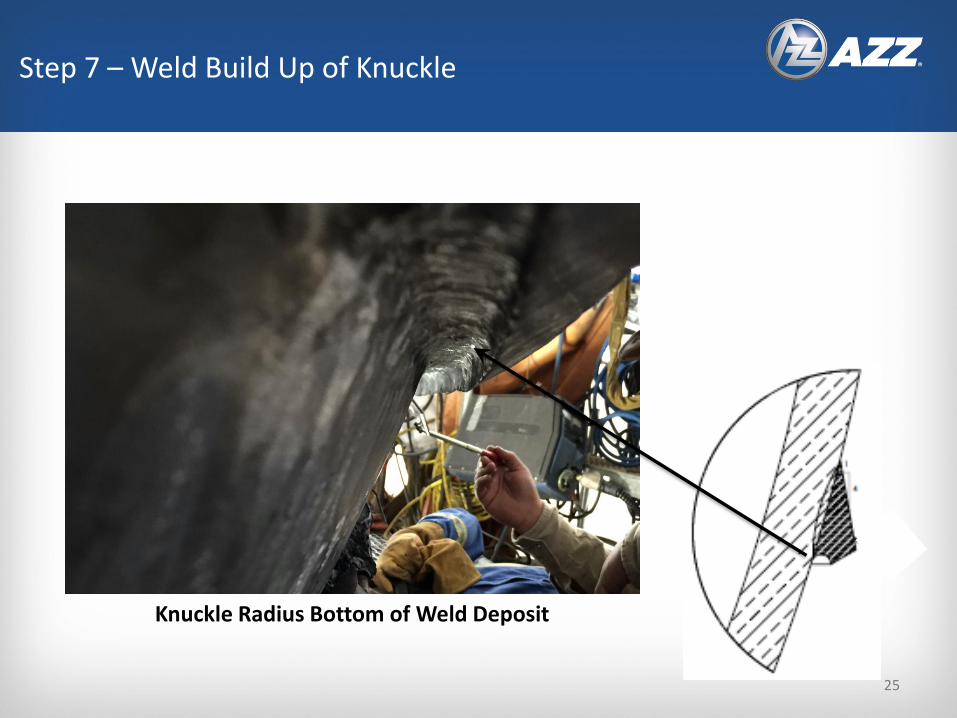
Knuckle Radius Bottom of Weld Deposit
Step 7 – Weld Build Up of Knuckle
25

Front Surface of Knuckle Weld Deposit
(After Blending and Surface Profiling)
Step 7 – Weld Build Up of Knuckle
26
27
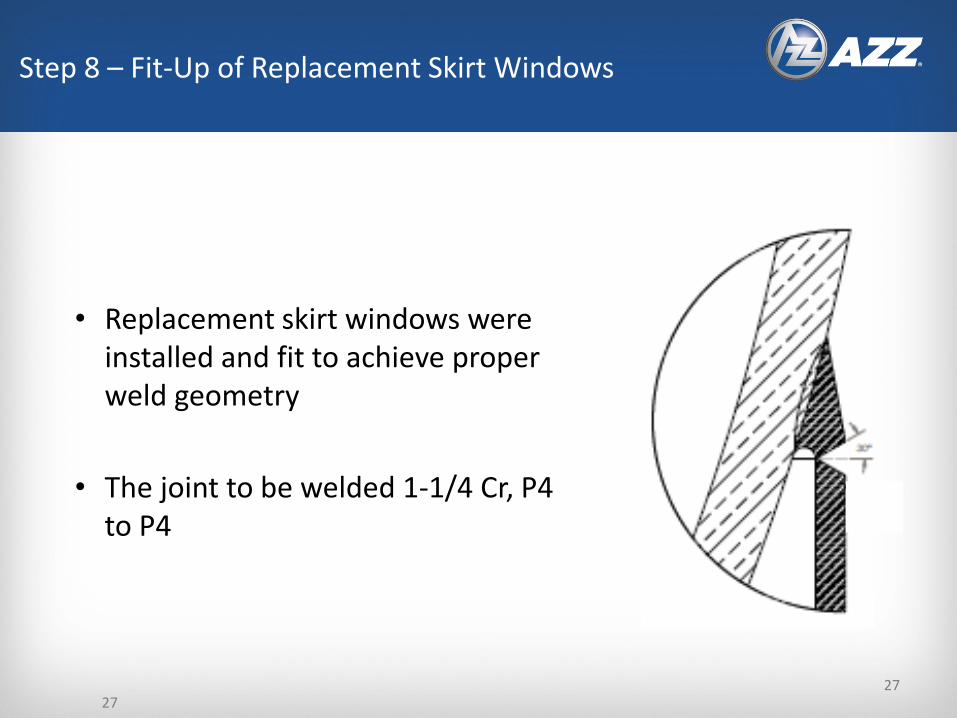
• Replacement skirt windows were installed and fit to achieve proper weld geometry
• The joint to be welded 1-1/4 Cr, P4 to P4
Step 8 – Fit-Up of Replacement Skirt Windows
27
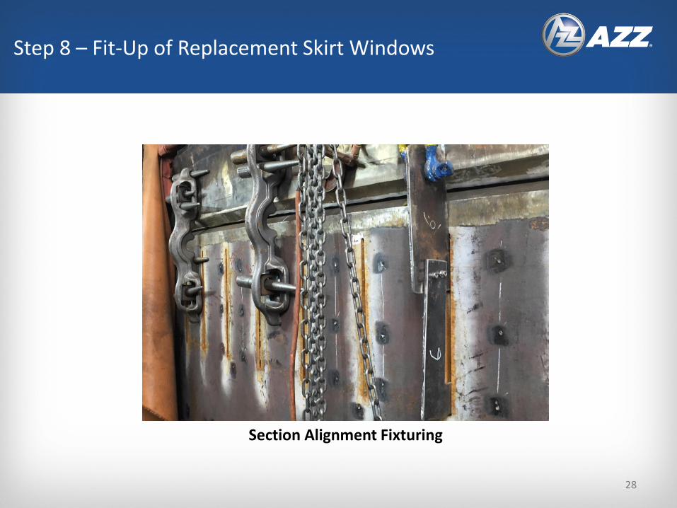
Section Alignment Fixturing
Step 8 – Fit-Up of Replacement Skirt Windows
28
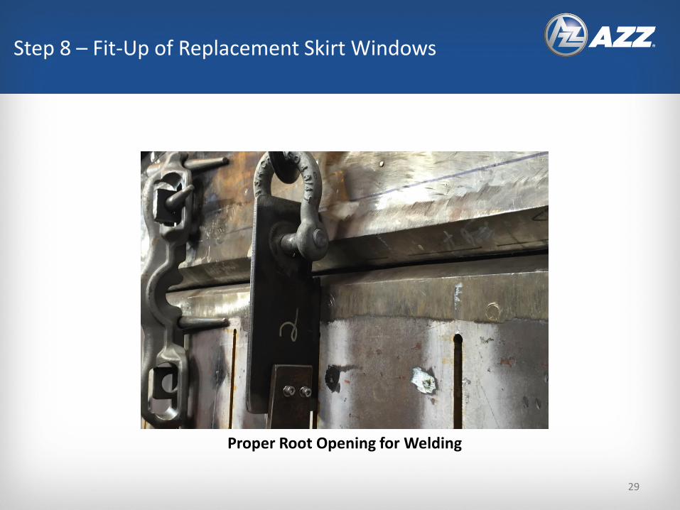
Proper Root Opening for Welding
Step 8 – Fit-Up of Replacement Skirt Windows
29
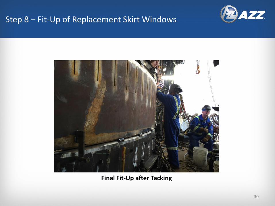
Final Fit-Up after Tacking
Step 8 – Fit-Up of Replacement Skirt Windows
30
31
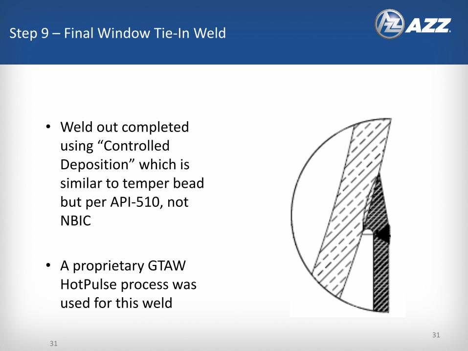
• Weld out completed using “Controlled Deposition” which is similar to temper bead but per API-510, not NBIC
• A proprietary GTAW HotPulse process was used for this weld
Step 9 – Final Window Tie-In Weld
31
32
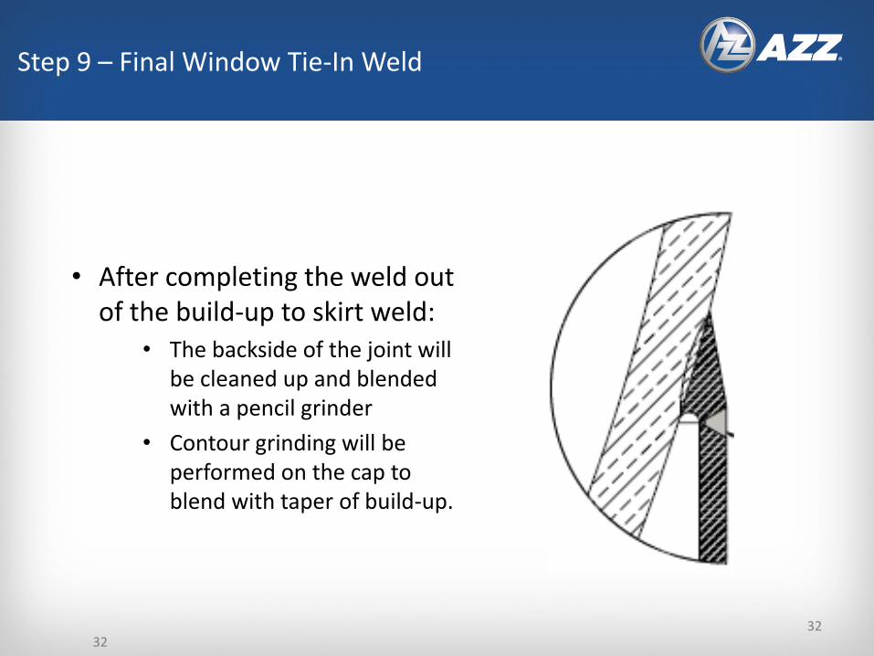
• After completing the weld out of the build-up to skirt weld:
• The backside of the joint will be cleaned up and blended with a pencil grinder
• Contour grinding will be performed on the cap to blend with taper of build-up.
Step 9 – Final Window Tie-In Weld
32
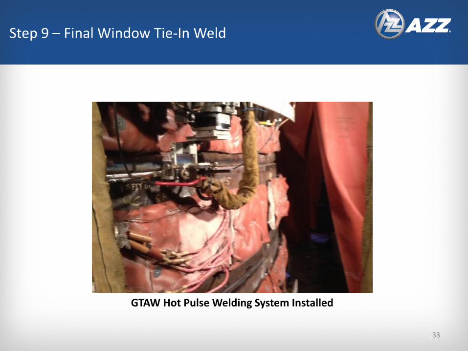
GTAW Hot Pulse Welding System Installed
Step 9 – Final Window Tie-In Weld
33

Better Photo of GTAW Hot Pulse on Mockup
Step 9 – Final Window Tie-In Weld
34

35
Step 9 – GTAW HotPulse Welding In Process
35
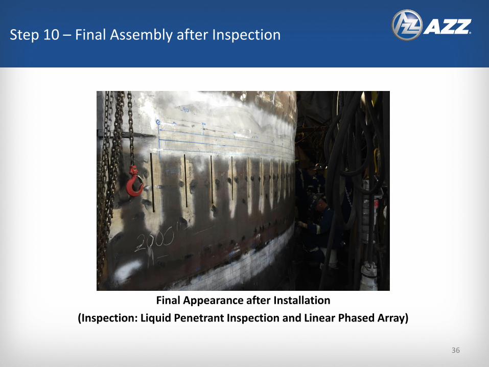
Final Appearance after Installation
(Inspection: Liquid Penetrant Inspection and Linear Phased Array)
Step 10 – Final Assembly after Inspection
36