Field experience with a Claus furnace checker wall
7
Field experience with a Claus furnace checker wall A new design of Claus furnace checker wall delivers improved mechanical performance and process flow characteristics Jeffrey Bolebruch Blasch Precision Ceramics Mossaed Y Al-Awwad Saudi Aramco Meng-Hung Chen CPC Corporation epending on the licensor, there are a number of different architectures that may be placed in the Claus furnace to influence performance. Each has its pros and cons. Regardless of design, mechanical stability has tradition- ally been problematic. Blasch was tasked to develop a checker wall that would be easy to install, mechanically stable under all conditions, allow for design with varying degrees of open area, and could incorporate the use of an integral manway, if desired. Concerns at this point were strictly mechanical; there were no requests for mixing or flow management. The goal was simply to put in a checker wall that could survive a campaign intact. The result was the Blasch HexWall TM checker wall. The blocks are designed to be stacked dry and are mechanically engaged through a series of tabs and slots, so the wall is quite stable, even when several meters in diameter. No mortar is used between the blocks, allowing the assembly to accommodate the thermally driven expansion and contraction that comes with reaction chamber operation. The blocks may also be reused. The initial checker wall blocks were designed to be 9in wide, the same as a row of bricks in the hotface. As larger furnaces were encountered, additional designs utilizing longer blocks were developed so as to retain a reasonable aspect ratio of wall width to height. The largest walls (>5m) utilize 18in wide blocks. The walls may either be erected into a slot in the existing lining, or installed against the hot face brick with a course of brick on either side to lock it in. The interlocking nature of the blocks makes provisions for expansion management straightforward and effective. The openings in the blocks are round, so that any portion of the block not directly supported by other blocks is in the form of an arch, and, as such, has greater mechanical stability than a flat span. Over the next several years, as time, temperature and turbulence were the variables that played the largest roles on the process constituents, the stability and durability of the checker walls was proven out, some operators, who previously spent their time rebuilding walls, began to question what they were actually designed to do — other than remain standing for an entire campaign. After considerable consultation with process licensors, engineering companies, end users, and miscellaneous stakeholders, it became apparent that almost everyone agreed that some combination of time, temperature and turbulence were the variables that played the largest roles on the process constituents. That makes sense, as the ‘three Ts’ of reaction kinetics, and their effects on process efficiency, are well documented. Blasch was determined to find a way to use the HexWall checker wall to influence these parameters. We selected turbulence, thinking that if we could improve mixing in the furnace, we could improve efficiency, but soon learned that they are all inter related, and we ended up learning a lot more about residence time, residence time distribution, and plug flow vs stirred tank design along the way. A vectoring hood was developed that would fit into the outlet ends of the existing blocks, and could be oriented and secured in the field in such a way as to redirect, or ‘vector’, the downstream flow allowing each individual block in the assembly to contribute to the creation of the overall desired flow. The vortex was initially selected because it was felt that this configuration made the best use of the furnace volume and created a flow pattern that yielded a long path length with a very tight residence time distribution. This variation of the HexWall checker wall was christened the VectorWall TM . There are now nearly two dozen VectorWalls installed worldwide, as well as approximately 100 of the earlier HexWalls. Highlighted below is a pair of VectorWall installations where it was possible to contrast stability related details from before and after the installation. Field experience with the VectorWall checker wall: mechanical One of the larger diameter VectorWalls done to date is installed in Saudi Aramco’s Berri Gas Plant, in its SRU200. This portion of the article is excerpted from a paper written by Mossaed Al- Awwad, Heat Transfer Engineer for the Aramco Consulting Services Department (CSD). Blasch gratefully D
Transcript of Field experience with a Claus furnace checker wall

Field experience with a Claus furnace checker wall A new design of Claus furnace checker wall delivers improved mechanical performance and process flow characteristics
Jeffrey Bolebruch Blasch Precision Ceramics Mossaed Y Al-Awwad Saudi Aramco Meng-Hung Chen CPC Corporation
epending on the licensor, there are a number of different architectures that may be placed in the Claus furnace to influence
performance. Each has its pros and cons. Regardless of design, mechanical stability has tradition- ally been problematic.
Blasch was tasked to develop a checker wall that would be easy to install, mechanically stable under all conditions, allow for design with varying degrees of open area, and could incorporate the use of an integral manway, if desired. Concerns at this point were strictly mechanical; there were no requests for mixing or flow management. The goal was simply to put in a checker wall that could survive a campaign intact.
The result was the Blasch HexWallTM checker wall. The blocks are designed to be stacked dry and are mechanically engaged through a series of tabs and slots, so the wall is quite stable, even when several meters in diameter. No mortar is used between the blocks, allowing the assembly to accommodate the thermally driven expansion and contraction that comes with reaction chamber operation. The blocks may also be reused.
The initial checker wall blocks were designed to be 9in wide, the same as a row of bricks in the hotface. As larger furnaces were encountered, additional designs utilizing longer blocks were developed so as to retain a reasonable aspect ratio of wall width to height. The largest walls (>5m) utilize 18in wide blocks.
The walls may either be erected into a slot in the existing lining, or installed against the hot face brick with a course
of brick on either side to lock it in. The interlocking nature of the blocks makes provisions for expansion management straightforward and effective. The openings in the blocks are round, so that any portion of the block not directly supported by other blocks is in the form of an arch, and, as such, has greater mechanical stability than a flat span.
Over the next several years, as
time, temperature and turbulence were the variables that played the largest roles on the process constituents, the stability and durability of the checker walls was proven out, some operators, who previously spent their time rebuilding walls, began to question what they were actually designed to do — other than remain standing for an entire campaign.
After considerable consultation with process licensors, engineering companies, end users, and miscellaneous stakeholders, it became apparent that almost everyone agreed that some combination of time, temperature and turbulence were the variables that played the largest roles on the process constituents. That makes sense, as the ‘three Ts’ of reaction kinetics, and their effects on process efficiency, are well documented.
Blasch was determined to find a way to use the HexWall checker wall to influence these parameters. We selected turbulence, thinking that if we
could improve mixing in the furnace, we could improve efficiency, but soon learned that they are all inter related, and we ended up learning a lot more about residence time, residence time distribution, and plug flow vs stirred tank design along the way.
A vectoring hood was developed that would fit into the outlet ends of the existing blocks, and could be oriented and secured in the field in such a way as to redirect, or ‘vector’, the downstream flow allowing each individual block in the assembly to contribute to the creation of the overall desired flow.
The vortex was initially selected because it was felt that this configuration made the best use of the furnace volume and created a flow pattern that yielded a long path length with a very tight residence time distribution. This variation of the HexWall checker wall was christened the VectorWallTM.
There are now nearly two dozen VectorWalls installed worldwide, as well as approximately 100 of the earlier HexWalls. Highlighted below is a pair of VectorWall installations where it was possible to contrast stability related details from before and after the installation.
Field experience with the VectorWall checker wall: mechanical One of the larger diameter VectorWalls done to date is installed in Saudi Aramco’s Berri Gas Plant, in its SRU200. This portion of the article is excerpted from a paper written by Mossaed Al-Awwad, Heat Transfer Engineer for the Aramco Consulting Services Department (CSD). Blasch gratefully
D

acknowledges Saudi Aramco for the following data.
Saudi Aramco’s Berri Gas Plant The current refractory system used on the internal reaction furnace lining in the Saudi Aramco sulphur recovery unit (SRU) is a dual layer of fire bricks as a hot face layer and a castable layer as back-up with stainless steel anchors to support the castable refractory. Part of this refractory system’s internal features is a checker wall that must be incorporated into the refractory hot face lining design. The existing checker wall system that was used for over 20 years frequently failed due to improper design and installation techniques. This article addresses the experience of a checker wall refractory system, the modified system and its impact on the reaction furnace operation.1
Refractory lining description The normal furnace operating temperature at Saudi Aramco SRU units is 1800-2000°F (980–1090°C); however, the hot face material must be capable of withstanding temperatures of 2500-3000°F (1370–1650°C) which
can occur during start-up firing of natural gas. All SRU reaction furnace linings should utilize at least 90% alumina hot face material.
Brick linings at the hot face layer are more durable than castable or plastic ram materials. The initial installation of brick may be slightly more expensive and require a highly skilled installer, but brick normally provides a longer lining life and requires less maintenance. Part of this refractory system’s internal lining is a checker wall that is made of a high density alumina brick system that has good high temperature strength to sustain the harsh environment.
Checker wall system main function The main function of the checker wall is to have proper gas mixing due to the residence time increasing as a result of improved destruction of H2S. In addition to that, the checker wall works as a protector to the tubesheet from radiant heat and other effects of process upsets. The exiting conventional checker walls installed in Saudi Aramco reaction furnaces either
have a cylindrical shape that resists high stress due to the geometry, or a matrix box shaped brick system jointed with mortar that normally failed due to thermal shock cycling, mortar failure and vibration.
Modified Claus process All Saudi Aramco SRUs use the Modified Claus process shown in Figure 1, where acid gas is initially treated in an acid gas scrubber and knock out drum to remove water, hydrocarbon liquids and diglycolamine. Then the acid gas is heated to 500ºF (260°C) in a pre-heater and introduced to a reaction furnace where a third of the H2S is burned in the presence of heated air to produce SO2. The generated SO2 reacts with the remaining H2S in three in-series catalytic stages to produce sulphur. Each stage contains an auxiliary burner (reheater), converter and a condenser. Liquid sulphur is collected from all condensers and stored in a sulphur pit where it is degassed and then exported. The unreacted H2S and other sulphur components, in the tail gas leaving the last condenser, are oxidized to SO2 in a thermal oxidizer.
Sulphur
No. 4
No. 3
No. 2
No. 1
Stack
Air
burner burner burner furnace
gas
LP
Steam
Steam drum
Knockout drum
Thermal oxidiser
Figure 1: Modified Claus Process employed by Saudi Aramco

Modified Claus reactions: 3 H2S + 3/2O2 → H2O + SO2 + 2H2S (1) 2 H2S + SO2 → 2H2O + 3/x Sx (2) Where x is = 1, 2, 3...
In a split flow configuration of the
Modified Claus process, a third of the acid gas passes through the reaction furnace and waste heat exchanger and the remaining fraction is mixed with the waste heat exchanger exit gases just before the first converter.
Hot process air comes from the air preheater at 700ºF (370°C) and 9 psig pressure to meet the acid gas line at the burner nozzle. The air is rationed to provide enough air to burn a third of the total H2S in the acid gas with no excess oxygen. The exact amount of air needed to maintain a H2S/SO2 ratio of 2:1 is controlled. The ratio of 2:1 H2S/SO2 must be obtained in the combustion chamber to progress all the way through the train. If there is more than 2:1 H2S/SO2 in the reaction furnace, the SO2 content of the gas will gradually lessen all the way through the train leaving an excess of H2S. If the ratio is less than 2:1 H2S/SO2 in the reaction furnace, the reverse happens with more SO2 remaining than H2S in the tail gas.
On the initial start-up of the plant, fuel gas is used to raise the temperature in the reaction furnace because the burning characteristics of the cold acid gas are poor. When the main burner is lit on fuel gas, the gas/air ratio is adjusted so that the fuel gas is burned stoichiometrically. Too much gas or substoichiometric fuel gas firing will deposit carbon on the catalyst and too much air or above stoichiometric fuel gas firing will cause a temperature runaway in the converter bed if there is sulphur present, due to the oxidation of the sulphur.
Fuel gas addition is normally used to warm up the train during start-up prior to acid gas admission and to clean up the converter beds before a planned shutdown. The hot process air and acid gas lines are provided with 75 psig steam injection. Steam is injected to maintain a stable flame and to keep the flame temperature below 2400°F (1315°C).
Investigative results The exiting conventional checker walls installed in Saudi Aramco’s reaction furnaces either have a cylindrical shape that resists high stress due to their geometry, or matrix box shape bricks jointed with mortar. Investigation revealed that the existing checker wall has a clear design deficiency and should be redesigned. The main cause of the failure was due to thermal cycling during the unit start-up and shut-down. Liquid carry-over to the combustion chamber loosens the brick system and causes complete failure. In addition to that, running the unit above its design capacity causes damage to the conventional checker wall as it cannot sustain high vibration due to over-design flow rate.
Figures 2 and 3 show damage caused to both checker wall designs.
Additional investigation revealed that, considering there were no drastic changes in the internal firing, gas composition and the external ambient conditions, the premature failure of the existing refractory system was due to several factors including the design, bricks quality, installation, and so on.
Investigative results and recommendations Saudi Aramco had bad experiences with the current checker designs due to:
repeated failures, short service life, prolonged repair shut- down, and extensive repair costs.
It is recommended to use an interlocking hexagonal ceramic block system which is made of ceramic (VectorWall, see Figure 4). Because of its special design, the modified system which has hexagonal shape increases capacity and lowers the operation and maintenance costs of medium and large diameter high temperature reaction chambers such as those used in Claus sulphur recovery units. This is accomplished by altering the reactant flow path creating significant mixing within the chamber thereby optimizing use of the avail- able volume within the chamber.
Field experience with the VectorWall checker wall: process CPC Corporation - Taoyuan refinery CPC Corporation, Taiwan (CPC) is the foremost energy enterprise in the Republic of China with nearly 15 000 employees and a variety of functional units around the island. As a state run enterprise, the company is responsible for the development and supply of petroleum and natural gas, and is the core of Taiwan’s petrochemical industry.2
CPC of Taiwan owns and operates three oil refineries, located at Kaohsiung, Dalin and Taoyuan,
Figure 2: Cylindrical shape conventional checker wall
Figure 3: Matrix box shape checker wall
Figure 4: VectorWall at Bern Gas Plant

respectively. The three refineries have a combined capacity of 720 000 b/d.3
The Kaohsiung refinery, which has the longest history of the three, is a large integrated oil refining and petrochemical production facility featuring a complex production process and a complete range of equipment. It has a capacity of 220 000 b/d of crude oil. The Dalin refinery, which split off from Kaohsiung to become independent in 1996, has four offshore mooring buoys as well as both large and small docks for the unloading and loading of crude oil and petroleum products. It has a topping capacity of
300 000 b/d. The Taoyuan Refinery was established in 1976 and, following some debottlenecking renovations and the addition of a second distillation plant, currently has a daily capacity of 200 000 bbl of crude oil.4
There are 15 sulphur recovery units within CPC. As a part of the Claus sulphur recovery process, the F6301 reaction furnace is the heart of No. 3 SRU at the Taoyuan refinery. It was designed to process the acid gas from an HDS (hydrodesulphurisation) plant in the refinery. The acid gas comes from two sources, the amine regeneration unit (ARU) ‘clean sour gas’ stream
containing mostly hydrogen sulphide and the sour water strip- per (SWS) ‘foul sour gas’ stream with roughly equal amounts of ammonia, hydrogen sulphide and water vapour.5
Figure 5 is a schematic of the F6301 reaction furnace. It is a refractory lined reactor with an inner diameter of 2.1 m and is about 9m long. A standard brick checker wall formerly divided the furnace into two zones. Acid gas from the HDS was introduced both at the burner and immediately down- stream of the checker wall. The hydrogen sulphide and ammonia in the acid gas were converted to elemental sulphur and SO2 and N2 respectively, in the furnace before exiting the waste heat boiler. The elemental sulphur condensed in the cooling tubes was removed at the liquid outlet. The leftover H S and the SO2 formed in the furnace reacted further downstream in a catalytic reactor to form more elemental sulphur.
The furnace was originally equipped with a conventional 9in brick checker wall. Prior to the retrofit, severe furnace vibration and noise were observed, especially at high furnace throughput. This was believed to have been caused by instability of the damaged checker wall. Thus it was not possible to operate the furnace at high temperatures, in particular in the first zone. In addition, deposits of ammonium bisulphate/sulphate were observed in the downstream equipment due to insufficient destructions of the ammonia in the furnace.
Retrofit In light of the above problems, CPC decided to revamp the furnace in May 2012. The revamp included installing a new insulation refractory for the entire furnace and replacing the checker wall
H2S
Fuel gas
Zone (II) Zone (I)
H2S + NH3
H2S
Figure 5: Schematic of Taoyuan refinery’s F6301 reaction furnace
Figure 6: A partially completed VectorWall
Figure 7: Flue gas temperatures before and after revamping
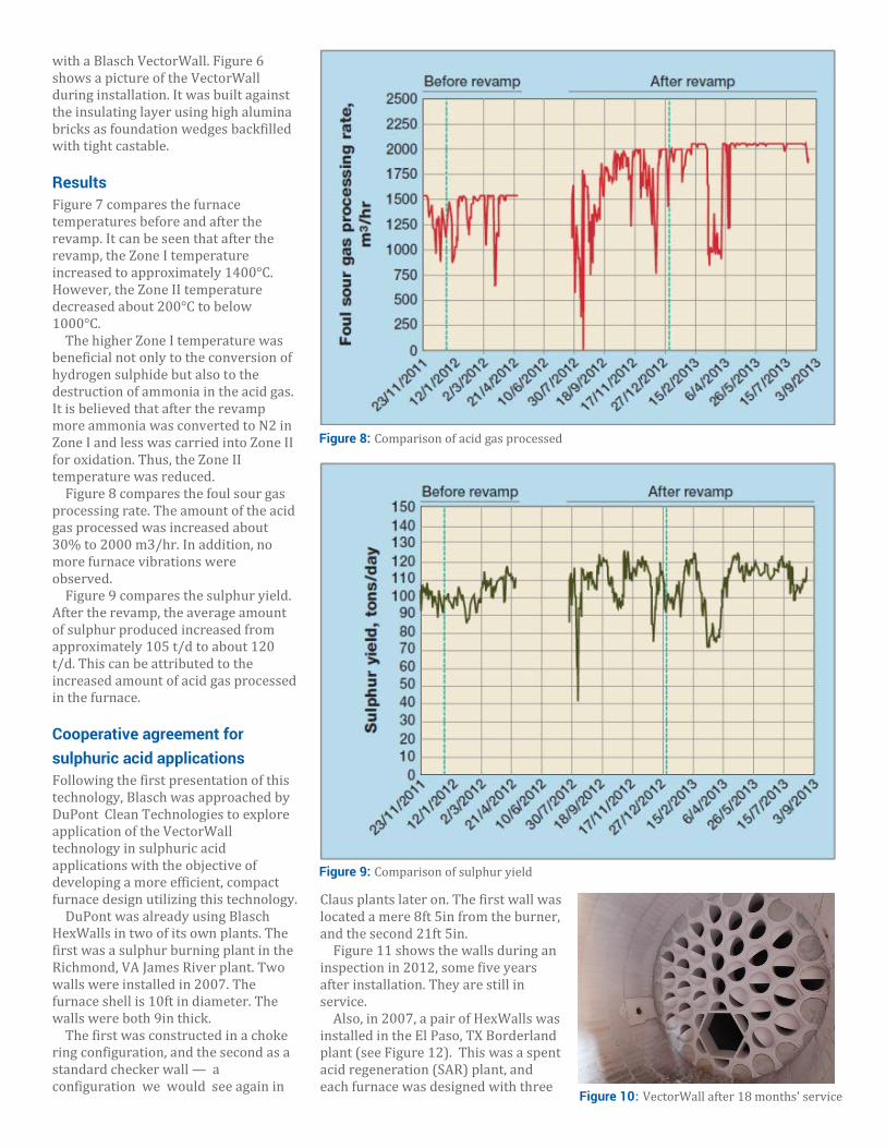
with a Blasch VectorWall. Figure 6 shows a picture of the VectorWall during installation. It was built against the insulating layer using high alumina bricks as foundation wedges backfilled with tight castable.
Results Figure 7 compares the furnace temperatures before and after the revamp. It can be seen that after the revamp, the Zone I temperature increased to approximately 1400°C. However, the Zone II temperature decreased about 200°C to below 1000°C.
The higher Zone I temperature was beneficial not only to the conversion of hydrogen sulphide but also to the destruction of ammonia in the acid gas. It is believed that after the revamp more ammonia was converted to N2 in Zone I and less was carried into Zone II for oxidation. Thus, the Zone II temperature was reduced.
Figure 8 compares the foul sour gas processing rate. The amount of the acid gas processed was increased about 30% to 2000 m3/hr. In addition, no more furnace vibrations were observed.
Figure 9 compares the sulphur yield. After the revamp, the average amount of sulphur produced increased from approximately 105 t/d to about 120 t/d. This can be attributed to the increased amount of acid gas processed in the furnace.
Cooperative agreement for sulphuric acid applications Following the first presentation of this technology, Blasch was approached by DuPont Clean Technologies to explore application of the VectorWall technology in sulphuric acid applications with the objective of developing a more efficient, compact furnace design utilizing this technology.
DuPont was already using Blasch HexWalls in two of its own plants. The first was a sulphur burning plant in the Richmond, VA James River plant. Two walls were installed in 2007. The furnace shell is 10ft in diameter. The walls were both 9in thick.
The first was constructed in a choke ring configuration, and the second as a standard checker wall — a configuration we would see again in
Claus plants later on. The first wall was located a mere 8ft 5in from the burner, and the second 21ft 5in.
Figure 11 shows the walls during an inspection in 2012, some five years after installation. They are still in service.
Also, in 2007, a pair of HexWalls was installed in the El Paso, TX Borderland plant (see Figure 12). This was a spent acid regeneration (SAR) plant, and each furnace was designed with three
Figure 8: Comparison of acid gas processed
Figure 9: Comparison of sulphur yield
Figure 10: VectorWall after 18 months' service

brick baffles. The first (underflow) walls in each were replaced with the HexWalls as this was before DuPont began to explore the VectorWall and its possibilities.
The mechanical stability of first (underflow) wall in a decomposition furnace is quite often problematic, and these are generally designed to be 18in thick when done in brick. These furnaces were a modest 12ft in diameter, and the HexWalls used were only 9in wide and were located 17ft from the burner.
Most recently, all three baffles in the new Burnside, LA SAR furnace came as Blasch HexWalls. This furnace was the largest done at DuPont to date, at
just under 19.5ft. The first wall was 18in wide and the remaining two were 13.5in.
At this point, Blasch began casting plugs for blocks it wished to blind, rather than casting them solid, which for very large walls was a good idea from a structural point of view.
At the time of this last installation, DuPont had not yet installed a complete VectorWall in a furnace, but after the performance of a considerable amount of modelling in Wilmington, DE, has now developed designs that are being marketed.
Interestingly, the Borderland Plant SAR was experiencing issues relative to NOx. A proprietary VectorWall based
solution was modelled and installed in both trains to work in conjunction with the existing baffle walls in 2012, and immediately resolved the concerns.
Furnace configuration and VectorWall performance So, what has been learned from all this? Access to software and hard- ware that can create a realistic, accurate, multiphysic (heat, mass, flow and kinetic) reactor simulation, and someone that can run it and analyse the results is hard to come by.
Blasch has definitely seen some trends from these installations, and is continuing to use the relatively simple cold flow modelling utilized during the development of the VectorWall, with a few tweaks.
The simplest furnace configuration is the straight through configuration (see Figure 13). All of the reactants enter at one time and in one place and react in similar fashion. Maximum efficiency in this type of situation comes from designing a flow configuration that creates the tightest residence time distribution, built around the optimal residence time for that particular process.
This configuration functions effectively as a plug flow reactor, and a consistent residence time with a long spiral path length, gives the most effective performance, assuming the furnace in question is the proper length for the process in question.
The real world, unfortunately, is not so tidy. Many times, in reality, you have much more complicated interactions, and the optimal solution is likely to be a compromise.
In Claus, often, one has to deal with sour water stripper gas, which contains ammonia, which if not destroyed early and with great enthusiasm, will create all sorts of downstream issues.
In these cases, the creation of multiple zones with unique characteristics is desired. For example, in the SWS case, higher temperatures in zone 1 are desirable to promote ammonia destruction, along with a degree of back mixing to properly blend it with the acid gas in that zone. In zone 2, lower temperatures are preferred, so as to discourage NOx creation, and a return to a tight residence time
Figure 11: Five years' service at James River
Figure 12: New HexWall (left) and after five years' service (right) in the Borderland plant
Figure 13: Straight through furnace design
distribution built around the optimal residence time.
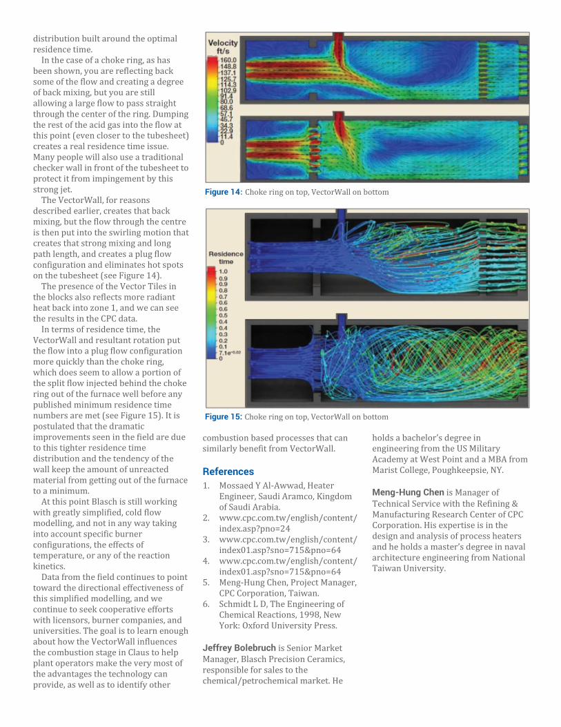
In the case of a choke ring, as has been shown, you are reflecting back some of the flow and creating a degree of back mixing, but you are still allowing a large flow to pass straight through the center of the ring. Dumping the rest of the acid gas into the flow at this point (even closer to the tubesheet) creates a real residence time issue. Many people will also use a traditional checker wall in front of the tubesheet to protect it from impingement by this strong jet.
The VectorWall, for reasons described earlier, creates that back mixing, but the flow through the centre is then put into the swirling motion that creates that strong mixing and long path length, and creates a plug flow configuration and eliminates hot spots on the tubesheet (see Figure 14).
The presence of the Vector Tiles in the blocks also reflects more radiant heat back into zone 1, and we can see the results in the CPC data.
In terms of residence time, the VectorWall and resultant rotation put the flow into a plug flow configuration more quickly than the choke ring, which does seem to allow a portion of the split flow injected behind the choke ring out of the furnace well before any published minimum residence time numbers are met (see Figure 15). It is postulated that the dramatic improvements seen in the field are due to this tighter residence time distribution and the tendency of the wall keep the amount of unreacted material from getting out of the furnace to a minimum.
At this point Blasch is still working with greatly simplified, cold flow modelling, and not in any way taking into account specific burner configurations, the effects of temperature, or any of the reaction kinetics.
Data from the field continues to point toward the directional effectiveness of this simplified modelling, and we continue to seek cooperative efforts with licensors, burner companies, and universities. The goal is to learn enough about how the VectorWall influences the combustion stage in Claus to help plant operators make the very most of the advantages the technology can provide, as well as to identify other
combustion based processes that can similarly benefit from VectorWall.
References 1. Mossaed Y Al-Awwad, Heater
Engineer, Saudi Aramco, Kingdom of Saudi Arabia.
2. www.cpc.com.tw/english/content/index.asp?pno=24
3. www.cpc.com.tw/english/content/ index01.asp?sno=715&pno=64
4. www.cpc.com.tw/english/content/ index01.asp?sno=715&pno=64
5. Meng-Hung Chen, Project Manager, CPC Corporation, Taiwan.
6. Schmidt L D, The Engineering of Chemical Reactions, 1998, New York: Oxford University Press.
Jeffrey Bolebruch is Senior Market Manager, Blasch Precision Ceramics, responsible for sales to the chemical/petrochemical market. He
holds a bachelor’s degree in engineering from the US Military Academy at West Point and a MBA from Marist College, Poughkeepsie, NY. Meng-Hung Chen is Manager of Technical Service with the Refining & Manufacturing Research Center of CPC Corporation. His expertise is in the design and analysis of process heaters and he holds a master’s degree in naval architecture engineering from National Taiwan University.
Figure 14: Choke ring on top, VectorWall on bottom
Figure 15: Choke ring on top, VectorWall on bottom