
FIELD DEVICES – RECORDERS - Eck-Boro · MODEL 6100AF AND 6180AF FEATURES PSS 2C-1C1 A Page 3...
20
FIELD DEVICES – RECORDERS Product Specifications Model 6100AF and Model 6180AF 6000 Series Paperless Graphic Recorders The Foxboro ® brand 6000 Series Paperless Graphic Recorders offer unrivaled input accuracy with a 125 ms total sample rate for up to 18 or up to 48 input channels, depending on the model selected. Input channels are freely configurable to suit your process requirements. Each instrument has an intuitive, touch screen display to enable operators to clearly view process data in varying formats. All have onboard Flash data storage capability, Ethernet communication, and a choice of removable media size and type, secure digital (SD) cards, and USB memory sticks. Data is stored in a tamper-resistant binary format that can be used for secure, long term records of your process. The 6000 Series is truly designed for today’s networked world and can be accessed via a Local Area Network (LAN), dial-up connection, intranet, or internet. FEATURES Color Touchscreen display. USB “plug and play.” Up to 96 MB nonvolatile flash memory. Ethernet TCP/ICP (Transmission Control Protocol/Internet Protocol). 125 ms parallel sampling. Web Server allows “read only” remote access to recorder. Data logging and archiving. Auditor meets requirements of FDA Regulation 21 CFR. Modbus RTU (Remote Terminal Unit). Supports Simple Network Time Protocol (SNTP) Batch Recording ASCII printer output. Event Input selection to initiate internal actions. Dynamic Host Configuration Protocol (DHCP). MODEL 6100AF MODEL 6180AF PSS 2C-1C1 A
-
Upload
truongcong -
Category
Documents
-
view
217 -
download
2
Transcript of FIELD DEVICES – RECORDERS - Eck-Boro · MODEL 6100AF AND 6180AF FEATURES PSS 2C-1C1 A Page 3...

FIELD DEVICES – RECORDERSProduct Specifications
PSS 2C-1C1 A
Model 6100AF and Model 6180AF6000 Series Paperless Graphic Recorders
The Foxboro® brand 6000 Series Paperless Graphic Recorders offer unrivaled input accuracy with a 125 ms total sample rate for up to 18 or up to 48 input channels, depending on the model selected. Input channels are freely configurable to suit your process requirements. Each instrument has an intuitive, touch screen display to enable operators to clearly view process data in varying formats. All have onboard Flash data storage capability, Ethernet communication, and a choice of removable media size and type, secure digital (SD) cards, and USB memory sticks. Data is stored in a tamper-resistant binary format that can be used for secure, long term records of your process. The 6000 Series is truly designed for today’s networked world and can be accessed via a Local Area Network (LAN), dial-up connection, intranet, or internet.
FEATURES
Color Touchscreen display.
USB “plug and play.”
Up to 96 MB nonvolatile flash memory.
Ethernet TCP/ICP (Transmission Control Protocol/Internet Protocol).
125 ms parallel sampling.
Web Server allows “read only” remote access to recorder.
Data logging and archiving.
Auditor meets requirements of FDA Regulation 21 CFR.
Modbus RTU (Remote Terminal Unit).
Supports Simple Network Time Protocol (SNTP)
Batch Recording
ASCII printer output.
Event Input selection to initiate internal actions.
Dynamic Host Configuration Protocol (DHCP).
MODEL 6100AF MODEL 6180AF

PSS 2C-1C1 APage 2 MODEL 6100AF AND 6180AF FEATURES
A perfect complement to the Invensys broad range of field instrument measurement solutions:
– Pressure Measurements– Temperature Measurements– Flow Measurements– Level Measurements– Conductivity Measurements– pH Measurements
User defined screens with Screen Builder.
Remote monitoring using Bridge software.
Review and Review/QuickChart software.
Easy mounting to a vertical panel, or to a panel sloped up to 45°, upward or downward.
Password controlled electronic front panel media flap lock.
EMC approved - CE and cUL.
Electrical Safety per BS EN61010.
MODEL 6100AF AND 6180AF FEATURES
(a) Virtual channels can be configured as maths, totalizers, counters, or comms.
Available Feature Model 6100AF Model 6180AF
Display 1/4 VGA, 5.5 in XGA, 12.1 in
Channels Up to 18 Up to 48
Relays Up to 12 Up to 27
Events Inputs 24 (6 per Option Card)
Groups 6 Standard (12 Optional)
Auditor Features Auditor or Audit Trail
Virtual Channels (a) 36, 96, 128
Timers 12 Fitted as Standard
Alarms 4 per Channel
Batch Optional Selection
Bridge-Remote Viewing Software
Bridge Lite is standard. Bridge Full also offered.
Screen Builder 24 (optional)
Security Unlimited unique user names with configurable access permissions and passwords.
Configuration Software Standard
Review or Review/QuickChart Software
Review or Review/QuickChart: Lite is standard. Full also offered.
Standard Views Vertical/Horizontal Trending and Bar GraphsCircular Trend/Numeric Values.
MODEL 6100AF AND 6180AF FEATURESPSS 2C-1C1 A
Page 3
COLOR TOUCHSCREEN DISPLAY
The 6000 Series Recorders are easy and intuitive to use, thereby insuring faster productivity and minimal learning requirements. Each recorder incorporates a “Pop Up” full “QWERTY” keyboard to facilitate data or message entry.
No Complicated Button Presses. Create Operator Buttons anywhere on Display. Intuitive Drop-Down Menus. Consistent Navigation Pre-defined Soft Keys. Integral Stylus.
DISPLAY BRIGHTNESS AND CLARITY
Use of state-of-the-art digital TFT display technology insures high screen definition and maximum clarity. A separate display processor optimizes screen refresh rates to allow operator-efficient viewing of all screens.
High Resolution VGA (6100AF) and XGA (6180AF) Display
Digital Display Technology Bright and Sharp Images 16-Bit Color 8 Hz Trend Speed Update
USB “PLUG AND PLAY”
“Plug and Play” peripherals allow these recorders to be connected in an easy and familiar manner so that they can be configured and operated based on specific application requirements.
Keyboard Mouse Memory Stick Bar Code Scanner
DATA LOGGING AND ARCHIVING
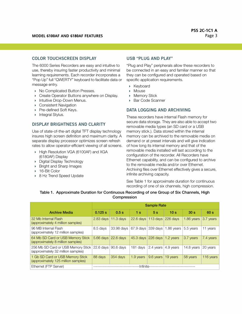
These recorders have internal Flash memory for secure data storage. They are also able to accept two removable media types (an SD card or a USB memory stick.). Data stored within the internal memory can be archived to the removable media on demand or at preset intervals and will give indication of how long its internal memory and that of the removable media installed will last according to the configuration of the recorder. All Recorders have Ethernet capability, and can be configured to archive to the removable media and/or over Ethernet. Archiving files over Ethernet effectively gives a secure, infinite archiving capacity.
See Table 1 for approximate duration for continuous recording of one of six channels, high compression.
Table 1. Approximate Duration for Continuous Recording of one Group of Six Channels, High Compression
Archive Media
Sample Rate
0.125 s 0.5 s 1 s 5 s 10 s 30 s 60 s
32 Mb Internal Flash(approximately 4 million samples)
2.83 days 11.3 days 22.6 days 113 days 226 days 1.86 years 3.7 years
96 MB Internal Flash(approximately 12 million samples)
8.5 days 33.98 days 67.9 days 339 days 1.86 years 5.5 years 11 years
64 Mb SD Card or USB Memory Stick(approximately 8 million samples)
5.66 days 22.6 days 45.3 days 226 days 1.2 years 3.7 years 7.4 years
256 Mb SD Card or USB Memory Stick(approximately 32 million samples)
22.6 days 90.6 days 181 days 2.4 years 4.9 years 14.8 years 20 years
1 Gb SD Card or USB Memory Stick (approximately 125 million samples)
88 days 354 days 1.9 years 9.6 years 19 years 58 years 116 years
Ethernet (FTP Server) -----------------------------------Infinite-----------------------------------

PSS 2C-1C1 APage 4 MODEL 6100AF AND 6180AF FEATURES
PASSWORD CONTROLLED ELECTRONIC FRONT PANEL MEDIA FLAP LOCK
The media flap (see DIMENSIONS-NOMINAL section) provides access to the stylus, media card, and USB port. This feature:
Insures that only a user having the correct authorization can open the flap.
Helps prevent theft or loss of media. Provides audit trail of which account opened the
flap.
WEB SERVER
This feature allows a user limited Read Only access to the Recorder from a remote PC, by:
Opening a standard internet browser. Typing-in the IP address of the recorder in the
form: http://xxx.xxx.xxx.xxx, or the “Local Host” name http://local host.
Entering the correct Remote User name and Remote Password (as set up in the Security/Access Menu).
AUDITOR FEATURES
Auditor
The Auditor is designed to meet the requirements of the FDA Regulation 21 CFR Part II for Electronic Records and Signatures. This software option provides the 6000 Series with additional security such as password aging, electronic signatures, and time stamped audit trail.
Audit Trail
The Audit Trail is a sub-set of the Auditor, and provides the 6000 Series with a time stamped audit trail. It does not include password aging and electronic signatures.
MODBUS MASTER
The MODBUS Master allows users to view data from multiple instruments connected either by a local Network connection using Modbus TCP, or a Serial connection using Modbus RTU.
TIME SYNCHRONIZATION (SNTP)
The 6000 Series support simple network time protocol which, when enabled, updates the instrument time every 15 minutes from the configured SNTP server. The unit can also act as a Unicast SNTP server on the network, allowing client instruments to synchronize with the Recorder to a resolution of one millisecond.
BATCH RECORDING
Up to ten user-defined fields can be used to enter batch specific data.
The user can choose to log any number of the given fields on start and/or stop of a batch. The information will appear on the chart as a message and cannot be separated from the process data to which it relates.
ASCII PRINTER OUTPUT (REPORTS)
Fitted as standard, the ASCII text printer option provides the 6000 Series with the ability to generate up to 10 simple reports that can be directed to a Serial ASCII text printer. Reports, triggered by an event/job, can be configured to contain parameters such as time and date, batch names, process values, and user defined messages.
EVENT INPUT
The Event input option offers six isolated event input circuits per board fitted. Triggered externally, these discrete inputs can be used to initiate internal actions within the 6000 Series Paperless Graphic Recorders. For example, they could be used to remotely start or stop a batch.
DYNAMIC HOST CONFIGURATION PROTOCOL (DHCP)
Dynamic Host Configuration Protocol, the successor to BootP, allows a 6000 Series host to obtain Network parameters, such as IP address, Subnet Mask, default gateway, and DNS server address dynamically. The implementation of DHCP on the 6000 Series significantly reduces the overhead for maintaining a network of instrumentation.
Field DescriptorOperator Entered Batch
Information
up to 20 characters up to 60 characters

STANDARD SPECIFICATIONSPSS 2C-1C1 A
Page 5
SCREEN BUILDER
Whatever the application, the operator interface can be simplified using the Screen Builder to easily produce customized displays showing the specific process. The operator can start/stop batches, download parameters, (e.g. control setpoint) and enter notes to be included with process record. Screens can contain standard elements (e.g. a trend or bar graph) along with imported image files, basic shapes, and buttons to drive events.
BRIDGE SOFTWARE
Bridge software gives complete remote access to the recorders. The software can be installed on any number of PCs and can connect to multiple recorders via a local network, dial-up connection, or the Internet. Each 6000 Series instrument can have 10 concurrent, independent, remote users connected to it, and viewing live data from the recorder. Ease of operator use is maintained as the displays and operation at the PC are the same as on the instrument. Data security is maintained with the use of specific user names and passwords.
REVIEW AND REVIEW/QUICKCHART
Review software acts as an efficient and secure library for data from which charts can be reviewed, printed, and exported to other PC packages if required. Archive files from a 6000 are stored in an encrypted, binary, check summed format and Review uses this format to enable chart view on a PC - ensuring integrity of both historical and new data. Review can access data from the recorder via a local network, dial-up connection, the internet or directly from the 6000’s removable media. Its Archive Management will help you to maintain growing data archives and manage files effectively.
Review/QuickChart provides a very quick and simple way of viewing historical data. It recreates the chart on the PC - the user can then add comments if they wish and re-save the chart, securing the comments. Review/QuickChart files can be viewed independently of the recorded process data and, as such, can be simply emailed for viewing by other users.
STANDARD SPECIFICATIONS
Environmental Performance
OPERATING TEMPERATURE LIMITS
0 and 50°C (32 and 122°F)
STORAGE TEMPERATURE LIMITS
-20 and +60°C (-4 and +140°F)
OPERATING RELATIVE HUMIDITY LIMITS
5 and 80% RH
STORAGE RELATIVE HUMIDITY LIMITS
5 and 90% RH
DEGREE OF PROTECTION
Bezel and Display: IEC IP66
Sleeve: IEC IP20
MECHANICAL SHOCK
BS EN61010
VIBRATION (10 to 150 Hz)
BS EN60873, Section 9.18
ALTITUDE
< 2000 m (< 6560 ft)
Electromagnetic Compatibility (EMC)
CE, cUL (UL File No. e57766)
Emissions and Immunity
BS EN61326

PSS 2C-1C1 APage 6 STANDARD SPECIFICATIONS
Electrical Safety (BS EN61010)
INSTALLATION CATEGORY II
The rate impulse voltage for equipment on a nominal 230 V ac mains is 2500 V.
POLLUTION DEGREE 2
Normally, only nonconductive pollution occurs. Occasionally, however, a temporary conductivity caused by condensation shall be expected.
Physical Specifications
PANEL MOUNTING
DIN 43700
PANEL MOUNTING ANGLE
Up to ±45° from vertical
DIMENSIONS
See DIMENSIONS-NOMINAL section
APPROXIMATE WEIGHT
Model 6100AF: 3 kg (6.6 lb)
Model 6180AF: 7 kg (15.4 lb)
Operator Interface
TYPE OF INTERFACE
Color TFT LCD with cold Cathode backlight, fitted with resistive, analog Touch Panel.
SIZE AND RESOLUTION
Model 6100AF: 1/4 VGA (320 x 240 pixels) 5.5 in
Model 6180AF: XGA (1024 x 768 pixels) 12.1 in
Power Requirements
SUPPLY VOLTAGE AND FREQUENCY
90 to 264 V ac, 45 or 65 Hz; or 110 to 370 V dc
POWER (MAXIMUM)
60 VA (Inrush Current 36 A)
FUSE TYPE
None
INTERRUPT PROTECTION
> 200 ms at 240 V ac (with Full Load)
Back-up Battery
TYPE
Poly-carbonmonofluoride/lithium (BR2330)
SUPPORT TIME (RTC)
1 year minimum with recorder unpowered
REPLACEMENT PERIOD
3 years
STORED DATA
Time; date; values for totalizers, counters and timers; batch data; Fvalue; rolling average; stopwatch; etc.

STANDARD SPECIFICATIONSPSS 2C-1C1 A
Page 7
Transmitter PSU - Isolated (6100AF Only)
Number of Outputs: Three
Output Voltage: 25 V Nominal
Maximum Current: 20 mA per Output
Isolation (dc to 65 Hz, BS 61010): Installation Category II; Pollution Degree 2
Channel to Channel Isolation: 100 V RMS or dc (double insulation)
Channel to Earth (Ground) Isolation: 100 V RMS or dc (basic insulation)
Fuse (20 mm Type T):
Supply Voltage = 110/120 V ac: 100 mA
Supply Voltage = 220/240 V ac: 63 mA
Communications
ETHERNET COMMUNICATIONS
Type: 10/100 baseT Ethernet, (IEEE 802.3)
Protocols: TCP/IP, FTP, DHCP, BOOTP, SNTP, MODBUS, SMTP, ICMP
Cable: CAT5 type; maximum length is 100 m (328 ft); RJ45 termination
SERIAL COMMUNICATIONS
Number of ports: 2
Protocol: ASCII(1); ASCII printer support; andMODBUS RTU master and slave.
Isolation (dc to 65 Hz, BS EN61010): Installation Category II; Pollution Degree 2
Terminal to Earth (Ground): 50 V RMS or dc (basic insulation)
Transmission Standard: EIA232 or EIA485 (software selectable)
Input Board
GENERAL
Input Types:
dc Volts, dc millivolts(2)
dc milliamps (with shunt)(3)
Thermocouple, 2/3-wire RTD Contact Closure (not Channels 1, 7, 13, 19,
25, 31, 37, 43): >60 ms
Input Type Mix:
Freely configurable
Maximum Number of Inputs:
6 per board
A/D Conversion Method:
>16 bits, 2nd order delta sigma
Input Ranges:
see Table 2 and Table 3.
Termination:
Edge connector /terminal block
Noise Rejection (48 to 62 Hz):
Common Mode: >140 dB (channel to channel and channel to ground).
Series Mode: >60 dB
Maximum Common Mode Voltage: 250 volts continuous
Maximum Series Mode Voltage:
45 mV at lowest range. 23.74 volts peak at highest range.
Isolation:
Channel to Channel: 300 V RMS or dc (double insulation)
Channel to Common Electronics: 300 V RMS or dc (double insulation)
Channel to Earth (Ground): 300 V RMS or dc (basic insulation)
(1) Typical ASCII applications: input of ASCII string inputs from Barcode readers, Credit Card readers, etc.(2) A 100:1 attenuator is required with each voltage input in excess of ±20 V dc. See Ordering Instructions.(3) A 250 shunt is required with each 4 to 20 mA input signal. See Ordering Instructions.

PSS 2C-1C1 APage 8 STANDARD SPECIFICATIONS
Dielectric Strength (BS EN61010) (1 minute tests):
Channel to Channel: 2500 V ac Channel to Earth (Ground): 1500 V ac
Insulation Resistance: >10 M at 500 V dc
Input Impedance:
38 mV, 150 mV, 1 V ranges: >10 M: 20 V range: 65.3 k
Overvoltage Protection: 50 volts peak (150 V with attenuator)
Open Circuit Detection: ±57 mA maximum
Recognition Time: 500 ms
Minimum Break Resistance: 10 M
UPDATE/ARCHIVE RATES
Input/Relay-Output Sample Rate: 8 Hz
Trend Update: 8 Hz maximum
Archive Sample-Value: Latest value at archive time
Display Value: Latest value at display update time (8 Hz)
DC INPUT RANGES
Shunt: Externally mounted resistor modules
Additional Error due to Shunt: 0.1% of input
Additional Error due to Attenuator: 0.2% of input
Performance: See Table 2.
RESISTANCE INPUTS
Ranges (including lead resistance): 0 to 150 , 0 to 600 , 0 to 6 k
Influence of Load Resistance:
Error: Negligible Mismatch: 1
Temperature Scale: ITS90
Accuracy and Resolution: See Table 3.
RTD Types and Ranges: See Table 5.
THERMOCOUPLE DATA
Temperature Scale: ITS 90
Bias Current: 0.05 nA
Cold Junction Types: Off, internal, external, remote
CJ Error: 1°C maximum with instrument at 25°C
CJ Rejection Ratio: 50:1 minimum
Upscale/Downscale Drive: High, low or user selectable for each TC channel
Additional Error: 0.01°C (typical) if high or low selected
Thermocouple Types and Ranges: see Table 4.
Table 2. Voltage Ranges - Accuracy and Resolution
Low RangeHigh
Range ResolutionTypical Error Range (Instrument at 20 °C)
Maximum Error Range (Instrument at 20 °C)
Worst Case Temperature Performance(Input per °C)
-38 mV 38 mV 1.4 µV 0.013% I/P + 0.031% 0.030% I/P + 0.052% 25 ppm
-150 mV 150 mV 5.5 µV 0.013% I/P + 0.028% 0.029% I/P + 0.039% 25 ppm
-1 V 1 V 37 µV 0.013% I/P + 0.024% 0.029% I/P + 0.029% 25 ppm
-20 V 20 V 720 µV 0.075% I/P + 0.027% 0.393% I/P + 0.033% 388 ppm

STANDARD SPECIFICATIONSPSS 2C-1C1 A
Page 9
Table 3. Resistance Ranges - Accuracy and Resolution
Low RangeHigh
Range ResolutionTypical Error Range (instrument at 20 °C)
Maximum Error Range (Instrument at 20 °C)
Worst Case Temperature Performance(Input per °C)
0 150 5 m 0.027% I/P + 0.034% 0.037% I/P + 0.077% 30 ppm
0 800 22 m 0.027% I/P + 0.035% 0.037% I/P + 0.057% 30 ppm
0 5 k 148 m 0.030% I/P + 0.034% 0.040% I/P + 0.041% 30 ppm
Table 4. Thermocouple Types and Ranges
TC Type Overall Range °C Standard Maximum Linearization Error
B 0 to 1820 IEC 584.1 0 to 400 °C: 1.7 °C400 to 1820 °C: 0.03 °C
C 0 to 2300 Hoskins 0.12°C
D 0 to 2495 Hoskins 0.08°C
E -270 to +1000 IEC 584.1 0.03°C
G2 0 to 2315 Hoskins 0.07°C
J -210 to +1200 IEC 584.1 0.02°C
K -270 to +1372 IEC 584.1 0.04°C
L -200 to +900 DIN43710:1985 (to IPTS68) 0.02°C
N -270 to +1300 IEC 584.1 0.04°C
R -50 to +1768 IEC 584.1 0.04°C
S -50 to +1768 IEC 584.1 0.04°C
T -270 to +400 IEC 584.1 0.02°C
U -200 to +600 DIN43710:1985 0.08°C
NiMo/NiCo -50 to +1410 ASTM E1751-95 0.06°C
Ni/NiMo 0 to 1406 Ipsen 0.14°C
Platinel 0 to 1370 Engelhard 0.02°C
P120%Rh/Pt40%Rh 0 to 1888 ASTM E1751-95 0.07°C
Table 5. 4 RTD Types and Ranges
RTD Type Overall Range °C StandardMaximum
Linearization Error
Cu10 -20 to +400 General Electric Co. 0.02°C
Cu53 -70 to +200 RC21-4-1966 <0.01°C
JPT100 -220 to +630 JIS C1604:1989 0.01°C
Ni100 -60 to +250 DIN 43760:1987 0.01°C
Ni120 -50 to +170 DIN 43760:1987 0.01°C
Pt100 -200 to +850 IEC 751 0.01°C
Pt100A -200 to +600 Eurotherm Recorders, SA 0.09°C
Pt1000 -200 to +850 IEC 751 0.01°C

PSS 2C-1C1 APage 10 STANDARD SPECIFICATIONS
Relay Output Board
GENERAL
Maximum Number of Relay Boards for Model 6100AF:
4 (maximum number of relay outputs = 12) 2 when using 18 input channels (maximum
number of relay outputs = 6)
Maximum Number of Relay Boards for Model 6180AF:
9 (maximum number of relay outputs = 27)
Number of Relays per Board:
3 per Form C Board (12 maximum)
Estimated Mechanical Life: 30,000,000 operations
Update Rate: See “Update Rates” in Input Board Specification section.
SAFETY ISOLATION
Isolation (dc to 65 Hz: BS EN 61010: Installation Category II; Pollution Degree 2
Relay to Relay: 300 V RMS or dc (double insulation)
Relay to Earth (Ground): 300 V RMS or dc (basic Insulation)
AC LOAD RATINGS
Derating: The figures provided are for resistive loads. For reactive or inductive loads, de-rate in accordance with Figure 1, in which:
F1 = Actually measured results on representative samples
F2 = Typical values according to experience
Contact Life = Resistive contact life X reduction factor
Maximum Switching Power: 500 VA
Maximum Contact Voltage: 250 V providing this does not cause the maximum switching power (above) to be exceeded.
Maximum Contact Current: 2 Amps providing this does not cause the maximum switching power (above) to be exceeded.
DC LOAD RATINGS
Maximum Switching Power: See Figure 2 for operating volt/amp envelope.
Maximum Contact Voltage/Current: See Figure 2 for examples.
Figure 1. Derating Curves for ac Loads
Figure 2. dc Load Switching Curves(Maximum dc Load Breaking Capacity)
1.00.9
0.8
0.7
0.6
0.5
0.4
0.3
RE
DU
CT
ION
FA
CTO
R, F
1.0 0.8 0.6 0.4 0.2POWER FACTOR (cos φ)
F1
F2
300
200
100
504030
20
dc V
OLT
AG
E, V
dc
101.0 0.2 0.5 1 2
dc CURRENT, A
5 20
RESISTIVE LOAD
INDUCTIVELOAD (L/R= 20 ms)

ELECTRICAL CONNECTIONSPSS 2C-1C1 A
Page 11
Event Input
Number of Inputs: 6 discrete inputs per Board
Number of Boards:
Model 6100AF: 4 boards, maximum Model 6180AF: 4 boards, maximum
Isolation:
Event Input to Ground: 100 V RMS or dc (basic insulation)
Event Input to Event Input: 0 V
Recognition Levels:
Active: -30 V to +0.8 V Inactive: +2 V to +30 V
Maximum Frequency: 8 Hz
Minimum Pulse Width: 62.5 ms
Contact Resistance:
Event:
Active if resistance <35 K Inactive if resistance >200 k Status not defined if resistance is >35 k
or < 200 k between input terminal and“C” terminal
Current Sink (Voltage I/P): 10 mA
ELECTRICAL CONNECTIONS
Figure 3. Input Board Wiring
Figure 4. Relay Board Wiring
Figure 5. Isolated Transmitter Power Supply Wiring (6100AF)
Figure 6. Event Board Wiring
221712 13 14 15 16 18 19 20 2110 1195 61 3 42 7 8
V- IV+ V- IV+ V- IV+ V- IV+ V- IV+ V- IV+
Channels2,8,14,20,
26,32,38,44
Channels1,7,13,19,
25,31,37,43
Channels3,9,15,21,
27,33,39,45
Channels5,11,17,23,29,35,41,47
Channels4,10,16,22,28,34,40,46
Channels6,12,18,24,30,36,42,48
CJC
nc
no
CONTACTS SHOWN IN POWEROFF/ALARM STATE
Three Form C Relays
221712 13 14 15 16 18 19 20 2110 1195 61 3 42 7 8
nc c nc nc c nc cnc nc nc c nc nc c nc c
Relay 1 Relay 2 Relay 3
nc nc
Maximum number of boards = 4 for small frame or 9 for large frame
Relay 1 Relay 2 Relay 32 OptionBoards
User Terminal Block
POWER SUPPLYPRINTED WIRING BOARD
LONG METALTERMINAL COVER CONTAINS POWER SUPPLYPWB; COVER ALSO PROTECTS ENTIREREAR SURFACEOF 6100AFRECORDER
Bla
ck
Red
Red
Red
Bla
ck
Bla
ck
THE “C” TERMINAL IS ISOLATED FROM RECORDER 0 V
666156 57 58 59 60 62 63 64 6554 555349 5045 47 4846 51 52
Option board No. 1 Option board No. 2
41 2 3 5 6 C5 61 3 42 C
5 61 3 42 C 5 61 3 42 C
INPUT 6 SHOWNINPUTS 1-5 AREIDENTICAL
+2 to +30 V
+0.8 to -30 V
User 0 V
VOLTAGE INPUTSCONTACT CLOSURE INPUTS

PSS 2C-1C1 APage 12 ELECTRICAL CONNECTIONS
Figure 7. Input Board SIgnal Wiring
Figure 8. Rear Surface Terminal Connections
V+ V- I V+ V- I V+ V- I V+ V- I V+ V- I V+ V- IV+ V- I
+ -
+ - + -DC V (-20 V to +20 V)
DC mVTHERMOCOUPLES
DC mADC V
(-200 V to +200 V)3-WIRE RESISTANCE
THERMOMETER2-WIRE RESISTANCE
THERMOMETERPOTENTIOMETER
CONTACT CLOSURE(NOT CHANNELS
1,7,13 etc.)
MINIMUM CONTACT= 60 ms
SHUNTASSEMBLY
ATTENUATORASSEMBLY
SHUNT ASSEMBLY100 Ω = LA246779UK10
ATTENUATORASSEMBLYLA244180150 Ω = LA246779UK25
Pin123456789
EIA232Not connectedReceive (RX)Transmit (TX)
DTR
Not connectedNot connectedNot connected
EIA4XXReceived (RXB)Not connectedNot connectedNot connected
Receive (RXA)Transmit (TXB)Transmit (TXA)
Common (0 V)
5.0 V through 1.5 k Ω
Serial Communications
usb1 usb2
1 2 3 4 5 1 2 3 4 5
6 7 8 9 6 7 8 9Serial 1 Serial 2
+V or ac 0 V or acEarth
(GROUND)
LOW SUPPLY VOLTAGE OPTION
1 2
37 - 42
3 4
25 - 30
1 - 6
13 - 18
43 - 49
31 - 36
7 - 12
19 - 24
5 6
7 8
9
1
1
1
1
22
22
22
22
1
1
1
1
22
22
22
22
1 2
7 - 12
3 4
1 - 6
1
1
1
1
22
22
22
22
OPTIONBOARD
OPTIONBOARD
INPUTCHANNELS
INPUTCHANNELS
INPUTCHANNELS
INPUTCHANNELS
OPTIONBOARDS
OPTIONBOARDS
OPTIONBOARDS
OPTIONBOARDS
INPUT
CHANNELS
INPUT
CHANNELS
INPUT
CHANNELS
OPTIONBOARDS
OPTIONBOARDS
INPUTCHANNELS
INPUTCHANNELS
CHANNELS 13 - 18 (IF FITTED) OCCUPYOPTION BOARD SLOTS 3 AND 4
6180AF
6100AF

MODEL CODE – 6100AF PAPERLESS GRAPHIC RECORDER
PSS 2C-1C1 APage 13
MODEL CODE – 6100AF PAPERLESS GRAPHIC RECORDER
Description ModelPaperless Graphic Recorder 6100AF
Number of Input Channels (a) 0 Input Channels - 4 Option Boards allowed with this Selection -06 Input Channels - 4 Option Boards allowed with this Selection -112 Input Channels - 4 Option Boards allowed with this Selection -218 Input Channels - 2 Option Boards allowed with this Selection -3
Password Controlled Electronic Media Flap LockNone NElectronic Lock on Media Flap L
Power Supply90 to 264 V ac, 45 to 65 Hz; or 110 to 370 V dc 1
24 V Isolated Transmitter Power SupplyNone (b) N110 to 120 V ac, 3 Channel TPS A220 to 240 V ac, 3 Channel TPS B
Internal Memory32 Mbyte for History - Typically 4 million samples 196 Mbyte for History - Typically 12 million samples 2
Memory Card SizeNone N128 Mbyte SD Card A256 Mbyte SD Card B1 Gbyte SD Card D
USB Memory Stick SizeNone 064 Mbyte USB Memory Stick 1256 Mbyte USB Memory Stick 21 Gbyte USB Memory Stick 4
USB Ports on Rear SurfaceNone N2 USB Ports on Rear Surface R
Serial Communication Ports on Rear SurfaceNone 02 EIA 232/485/422 Serial Communication Ports on Rear Surface 1
Form C Relays (a)None N3 Form C Relays (Comprises 1 Option Board) A6 Form C Relays (Comprises 2 Option Boards) B9 Form C Relays (Comprises 3 Option Boards) C12 Form C Relays (Comprises 4 Option Boards) D
Event Inputs (a)None 06 Event Inputs (Comprises 1 Option Board) 112 Event Inputs (Comprises 2 Option Boards) 218 Event Inputs (Comprises 3 Option Boards) 324 Event Inputs (Comprises 4 Option Boards) 4
Analog Outputs (Required Selection even if not Available)None N

PSS 2C-1C1 APage 14
MODEL CODE – 6100AF PAPERLESS GRAPHICRECORDER
a) The total combined option boards allowed for Form C Relays plus Even Inputs is 4 for Input Channel Selections 0, 1, and 2; however for Input Channel Selection 3, the number of combined option boards is 2. For example, when selecting Input Channel 2, you can have:
4 Form C Relay Boards (Selection Code D), and0 Event Input Boards (Selection Code 0)
Or you can have:2 Form C Relay Boards (Selection Code B), and2 Event Input Boards (Selection Code 2).
Bridge - Remote Viewing SoftwareBridge Lite (Standard) 1Bridge Full 2
Review and Review/QuickChart SoftwareReview Lite and Review/QuickChart Lite (Standard) LReview Full and Review/QuickChart Full F
AuditorNone 0Audit Trail 1Auditor 2
Security ManagerNone NSecurity Manager S
Groups6 Groups (Standard) 112 Groups 2
Maths, Totalizers, and CountersNone N36 Virtual Channels A96 Virtual Channels B128 Virtual Channels C
BatchNone 0Batch 1
Screen BuilderNone NAdvanced Screen Builder A
Master CommunicationsNone 0Modbus Master Communications for 16 Slaves 1Modbus Master Communications for 32 Slaves 2
Example: 6100AF–2L1A1B2R1A2N1L2S1A1A0f
MODEL CODE – 6100AF PAPERLESS GRAPHIC RECORDER (CONTINUED)
Description Model

MODEL CODE – 6180AF PAPERLESS GRAPHIC RECORDER
PSS 2C-1C1 APage 15
MODEL CODE – 6180AF PAPERLESS GRAPHIC RECORDER
Description ModelPaperless Graphic Recorder 6180AF
Number of Input Channels0 Input Channels - 9 Option Boards allowed with this selection. -06 Input Channels - 9 Option Boards allowed with this selection. -112 Input Channels - 9 Option Boards allowed with this selection. -218 Input Channels - 9 Option Boards allowed with this selection. -324 Input Channels - 9 Option Boards allowed with this selection. -430 Input Channels - 9 Option Boards allowed with this selection. -536 Input Channels - 9 Option Boards allowed with this selection. -642 Input Channels - 9 Option Boards allowed with this selection. -748 Input Channels - 9 Option Boards allowed with this selection. -8
Password Controlled Electronic Media Flap LockNone NElectronic Lock on Media Flap L
Power Supply90 to 264 V ac, 45 to 65 Hz; or 110 to 370 V dc 1
24 V Isolated Transmitter Power Supply (Required Selection even though not used)Not used on Model 6180AF (Available with Model 6100AF only) N
Internal Memory32 Mbyte for History - Typically 4 million samples 196 Mbyte for History - Typically 12 million samples 2
Memory Card SizeNone N128 Mbyte SD Card A256 Mbyte SD Card B1 Gbyte SD Card D
USB Memory Stick SizeNone 064 Mbyte USB Memory Stick 1256 Mbyte USB Memory Stick 21 Gbyte USB Memory Stick 4
USB Ports on Rear SurfaceNo Rear USB Ports N2 USB Ports on Rear Surface R
Serial Communication Ports on Rear SurfaceNone 02 EIA 232/485/422 Serial Communication Ports on Rear Surface 1
Form C Relays (a)None N3 Form C Relays (Comprises 1 Option Board) A6 Form C Relays (Comprises 2 Option Boards) B9 Form C Relays (Comprises 3 Option Boards) C12 Form C Relays (Comprises 4 Option Boards) D15 Form C Relays (Comprises 5 Option Boards) E18 Form C Relays (Comprises 6 Option Boards) F21 Form C Relays (Comprises 7 Option Boards) G24 Form C Relays (Comprises 8 Option Boards) H27 Form C Relays (Comprises 9 Option Boards) J

PSS 2C-1C1 APage 16
MODEL CODE – 6180AF PAPERLESS GRAPHICRECORDER
a) The maximum number of Option Boards available is 9; the nine combines the Form C Relay plus the Event Input. For example, selection could be:
6 Form C Relay Option Boards (18 Form C Relays - Selection Code F)3 Event Input Option Boards (18 Event Inputs - Selection Code 3).
Event Inputs (a)None 06 Event Inputs (Comprises 1 Option Board) 112 Event Inputs (Comprises 2 Option Boards) 218 Event Inputs (Comprises 3 Option Boards) 324 Event Inputs (Comprises 4 Option Boards) 4
Analog Outputs (Required Selection even if not Available)None N
Bridge - Remote View SoftwareBridge Lite (Standard) 1Bridge Full 2
Review and Review/QuickChart SoftwareReview Lite and Review/QuickChart Lite (Standard) LReview Full and Review/QuickChart Full F
AuditorNone 0Audit Trail 1Auditor 2
Security ManagerNone NSecurity Manager S
Groups6 Groups - Standard Selection 112 Groups 2
Maths, Totalizers, and CountersNone N36 Virtual Channels A96 Virtual Channels B128 Virtual Channels C
BatchNone 0Batch 1
Screen BuilderNone NAdvanced Screen Builder A
Master CommunicationsNone 0Modbus Master Communications for 16 Slaves 1Modbus Master Communications for 32 Slaves 2
Example: 6180AF–4L1N2B2R1F3N1L2S1A0A0
MODEL CODE – 6180AF PAPERLESS GRAPHIC RECORDER (CONTINUED)
Description Model
DIMENSIONS – NOMINALPSS 2C-1C1 A
Page 17
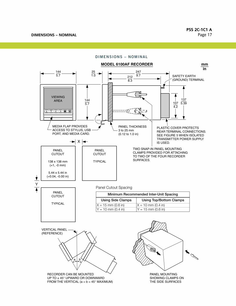
DIMENSIONS – NOMINAL
1445.7
2479.7212
8.3
251.0
1445.7
1375.39107
4.2
X
Y
PLASTIC COVER PROTECTS REAR TERMINAL CONNECTIONS.SEE FIGURE 5 WHEN ISOLATEDTRANSMITTER POWER SUPPLYIS USED.
SAFETY EARTH(GROUND) TERMINAL
VIEWINGAREA
MEDIA FLAP PROVIDES ACCESS TO STYLUS, USBPORT, AND MEDIA CARD.
PANEL THICKNESS3 to 25 mm (0.12 to 1.0 in)
TWO SNAP-IN PANEL MOUNTINGCLAMPS PROVIDED FOR ATTACHINGTO TWO OF THE FOUR RECORDERSURFACES.
a b
VERTICAL PANEL(REFERENCE)
PANELCUTOUT
PANELCUTOUT
TYPICAL
PANELCUTOUT
TYPICAL
138 x 138 mm(+1, -0 mm)
5.44 x 5.44 in(+0.04, -0.00 in)
RECORDER CAN BE MOUNTED UP TO ± 45° UPWARD OR DOWNWARD
PANEL MOUNTINGSHOWING CLAMPS ON
mmin
MODEL 6100AF RECORDER
Panel Cutout Spacing
Minimum Recommended Inter-Unit Spacing
Using Side Clamps Using Top/Bottom ClampsX = 15 mm (0.6 in) X = 10 mm (0.4 in)Y = 10 mm (0.4 in) Y = 15 mm (0.6 in)
FROM THE VERTICAL (a = b = 45° MAXIMUM) THE SIDE SURFACES

PSS 2C-1C1 APage 18 DIMENSIONS – NOMINAL
26210.3212
8.3
27910.98
2168.5
METAL COVER PROTECTS REAR TERMINAL CONNECTIONS.
SAFETY EARTH(GROUND) TERMINAL
PANEL THICKNESS6 to 25 mm (0.24 to 1.0 in)
TWO SNAP-IN PANEL MOUNTINGCLAMPS PROVIDED FOR ATTACHINGTO TWO OF THE FOUR RECORDERSURFACES.
281.1
X
Y
PANELCUTOUT
PANELCUTOUT
TYPICAL
PANELCUTOUT
TYPICAL
281 x 281 mm(+1, -0 mm)
11.07 x 11.07 in(+0.04, -0.00 in)
VERTICAL PANEL(REFERENCE)
a b
29211.5
MEDIA FLAP PROVIDES ACCESS TO STYLUS, USB PORT, AND MEDIA CARD.
29211.5
mmin
MODEL 6180AF RECORDER
Panel Cutout Spacing
Minimum Recommended Inter-Unit Spacing
UsingSide Clamps
UsingTop/Bottom Clamps
X = 25 mm (1 in) X = 12.5 mm (0.5 in)Y = 12.5 mm (0.5 in) Y = 25 mm (1 in)
RECORDER CAN BE MOUNTED UP TO ± 45° UPWARD OR DOWNWARD FROM THE VERTICAL (a = b = 45° MAXIMUM)
PANEL MOUNTINGSHOWING CLAMPS ON THE SIDE SURFACES

NOTESPSS 2C-1C1 A
Page 19
NOTES

PSS 2C-1C1 APage 20
ORDERING INSTRUCTIONS
OTHER M&I PRODUCTS
1. Model Number
2. Required Auxiliary Specification:- Specify quantity of 250 shunts, Part Number BS812UJ- One shunt required for each 4 to 20 mA input signal
3. Specify quantity of 100:1 attenuator, Part Number BS812TJ- one attenuator required for each V dc input in excess of ±20 V dc- NOTE: voltage inputs less than ±20 V dc do not require an attenuator
4. Tag and Application
Invensys provides a broad range of measurement and instrument products, including solutions for pressure, flow, analytical, positioners, temperature, controlling and recording. For a listing of these offerings, visit the Invensys Operations Management web site at:
www.iom.invensys.com
Invensys Operations Management5601 Granite Parkway Suite 1000Plano, TX 75024United States of Americahttp://iom.invensys.com
Global Customer SupportInside U.S.: 1-866-746-6477Outside U.S.: 1-508-549-2424 or contact your local Invensys representative.Website: http://support.ips.invensys.com
Invensys and Foxboro are trademarks of Invensys plc, its subsidiaries, and affiliates.All other brand names may be trademarks of their respective owners.
Copyright 2007-2013 Invensys Systems, Inc.All rights reserved
MB 010 0513


![[1C1]Service Workers](https://static.fdocuments.in/doc/165x107/547e8828b4af9fea158b560a/1c1service-workers.jpg)


![[PSS 6-1C1 E] 873 Series Electrochemical Analyzers SERIES.pdf · Product Specifications PSS 6-1C1 E 873 Series Electrochemical Analyzers pH, ORP, Ion Selective, Contacting Conductivity](https://static.fdocuments.in/doc/165x107/5a9da8677f8b9a28388cd882/pss-6-1c1-e-873-series-electrochemical-seriespdfproduct-specifications-pss-6-1c1.jpg)
