FIELD DEVICES – POSITIONERS€¦ · FIELD DEVICES – POSITIONERS Product Specifications Model...
12
FIELD DEVICES – POSITIONERS Product Specifications Model E69P Current-to-Pneumatic Valve Positioner Valve-Mounted The Foxboro ® brand E69P Valve Positioner, mounted directly on a pneumatic valve yoke, converts a standard direct current input signal to a proportional valve stem position. It eliminates the need for a separate converter plus a separate positioner. As symbolized by the “CE” Logo marking on the product, these valve positioners conform to the applicable European Union directives. COMPACT POSITIONER EASILY MOUNTED ON VALVE YOKE Because of its small size, compact design, and simple connection mechanism, the Model E69P Valve Positioner can be quickly and conveniently mounted on a wide variety of valve or other types of pneumatic actuators. VIBRATION AND INCLINATION EFFECTS MINIMIZED Pipe line vibration normally encountered has minimal effect upon the E69P. Also, the effects of inclination are minimal, allowing the valve to be mounted without regard for the attitude of the positioner. Low mass components, along with a statically balanced and well-supported coil in the galvanometric motor of the E69P, make these important benefits possible. MULTIPLE APPLICATIONS With choice of input, choice of direct or reverse action, split input ranges, and availability of standard or explosionproof covers, this positioner can be easily adapted for a wide range of applications. PSS 4-10A2 A
Transcript of FIELD DEVICES – POSITIONERS€¦ · FIELD DEVICES – POSITIONERS Product Specifications Model...

FIELD DEVICES – POSITIONERSProduct Specifications
PSS 4-10A2 A
Model E69P Current-to-Pneumatic Valve Positioner Valve-Mounted
The Foxboro® brand E69P Valve Positioner, mounted directly on a pneumatic valve yoke, converts a standard direct current input signal to a proportional valve stem position. It eliminates the need for a separate converter plus a separate positioner. As symbolized by the “CE” Logo marking on the product, these valve positioners conform to the applicable European Union directives.
COMPACT POSITIONER EASILY MOUNTED ON VALVE YOKE
Because of its small size, compact design, and simple connection mechanism, the Model E69P Valve Positioner can be quickly and conveniently mounted on a wide variety of valve or other types of pneumatic actuators.
VIBRATION AND INCLINATION EFFECTS MINIMIZED
Pipe line vibration normally encountered has minimal effect upon the E69P. Also, the effects of
inclination are minimal, allowing the valve to be mounted without regard for the attitude of the positioner. Low mass components, along with a statically balanced and well-supported coil in the galvanometric motor of the E69P, make these important benefits possible.
MULTIPLE APPLICATIONS
With choice of input, choice of direct or reverse action, split input ranges, and availability of standard or explosionproof covers, this positioner can be easily adapted for a wide range of applications.

Page 2 PERFORMANCE SPECIFICATIONS
MINIMAL EFFECTS FROM AMBIENT ATMOSPHERIC CONDITIONS
The design of the unique galvanometric motor in the E69P provides for generous clearances between coil and housing. Normal atmospheric changes,
which may cause corrosion and dust particles, do not hinder operation of the mechanism, as sometimes happens with voice coil type instruments.
PERFORMANCE SPECIFICATIONS
(All values are for normal input ranges)
Linearity
±1% of span
Repeatability
0.1%
Dead Band
0.1% input, relative to output pressure response.
Open Loop Gain
Nominally 80
Supply Pressure Effect
A change in supply pressure causes a zero shift of less than 0.04% of span per kPa or ±0.25% per psi.
Inclination Effect
Maximum zero shift is 0.25% of span for a 5 degree angular change in inclination from the vertical. This error can be eliminated by calibrating instrument at its intended mounting position.
FUNCTIONAL SPECIFICATIONS
Input Signal Ranges
Nominal Output Signal(1)
Full operating supply pressure delivered to actuator on small changes of input signal. Mechanical feedback ensures that the actuator stem is always moved to the position corresponding to the input signal value. Table below lists output signal ranges.
Instrument Adjustments
Zero
Provided by externally located screwdriver adjustment.
Range
Provided by internally located screwdriver adjustment.
Ambient Temperature Limits
-40 and +80°C (-40 and 180°F).
Relative Humidity Operative Limits
0 and 100% RH; no condensate
Normal Range Split Ranges
Input Impedance
4 to 20 mA 4 to 12 or 12 to 20 mA 170 Ω10 to 50 mA 10 to 30 or 30 to 50 mA 27 Ω
1. Supply Pressure must be at least 20 kPa, 3 psi, or 0.2 bar greater than output signal.
kPa psi bar or kg/cm2
0 to 240 0 to 35 0 to 2.4
0 to 420 0 to 60 0 to 4.2

PHYSICAL SPECIFICATIONS Page 3
Positioner Action (as specified)
Direct
Increased input increases the output
Reverse
Increased input decreases the output
PHYSICAL SPECIFICATIONS
Data Plate
Aluminum data label fastened to housing with pressure sensitive adhesive. Includes space for customer tag data up to a maximum of 86 characters and spaces. For additional space, see optional Customer Tag.
Enclosure
Diecast low copper aluminum alloy body and cover, with an epoxy powder finish. The enclosure meets the weatherproof rating of IEC IP65 as defined by IEC 60529 and provides the environmental protection rating of NEMA 4.
Mounting
Vertical on valve yoke. See “Lever Assembly Kit” on page 4.
Input/Output Connections
Electrical
Tapped for 1/2 inch conduit fitting. Provided with a pair of 0.5 m (18 in) long, 18 AWG twisted leads.
Pneumatic
1/4 NPT for air supply and output signal.
Approximate Mass
2.3 kg (5 lb)
Air Consumption (at standard conditions)
Supply Pressure
Air Consumption
m2/h scfm
240 or 415 kPa, or35 or 60 psi, or2.4 or 4.1 bar or kg/cm
1.7 1.0
140 kPa, 20 psi, or 1.4 bar or kg/cm2
1.3 0.75
Air Handling Capacity (at standard conditions)
Output Signal Code
Supply Exhaust
m3/h scfm m3/h scfm
1 1.9 1.1 1.5 0.90
9 6.8 4.0 2.2 1.3
Supply Pressure (a)
a. Supply pressure must not be less than 20 kPa, 3 psi, 0.2 bar, or 0.2 kg/cm2 above the maximum output signal pressure.
Nominal Operative Limits
kPa psibar or
kg/cm2 kPa psibar or
kg/cm2
140 20 1.4 130 and 260 19 and 38 1.3 and 1.6
240 35 2.4 225 and 260 33 and 38
2.3 and 2.6
415 60 4.1 400 and 435 58 and 63
4.0 and 4.3

Page 4 PHYSICAL SPECIFICATIONS
Lever Assembly Kit
Lever Assembly Kits are typically provided using a Model Code selection (see “Model Code” on page 7). They can also be ordered by part number when the positioners are ordered separate from the valve (Lever Assembly Codes S, T, U, Q, R, and V). See table below.
Dimensions
Refer to “Dimensions—Nominal” on page 8, and to Dimensional Print DP 018-430.
Lever Assembly Kit Part Numbers
Foxboro Valve Model
Foxboro Actuator Model
Assembly Kit Model Code (a)
Assembly Kit Part No.
V1 P25, P50 S B0157YS
V1 P110 T B0157YT
V9000, V9300 P50, P110 U B0157YU
Other than V1 or V9000 (b)
P25, P50 Q B0157YQ
Other than V1, V9000, or V9300 (b)
P110 R B0157YR
Universal Lever Assembly Kit
P25, P50, P110, and all other Actuators
V B0157YV
a. Assembly Kit Model M is not listed since the Valve, Actuator, and Lever Kit are assembled by Foxboro.
b. Hammer lug yokes.

ELECTRICAL SAFETY SPECIFICATIONS Page 5
ELECTRICAL SAFETY SPECIFICATIONS
Input Signal (mA)
Testing Laboratory
Types of Protection, Area Classification,
and Application ConditionsAvailable
with Model
Electrical Classification
Code
4 to 20or
10 to 50
FM FM approved explosionproof for Class I, Groups C and D, Division1; and dust-ignitionproof for Class II, Groups E and G, Division 1. Temperature Class T6.
E69P -T only
CS-E/FD-A (a)
a. Use of the optional PG11 Cable Gland is not allowed. Use a flameproof cable gland instead.
FM approved nonincendive for Class I, Groups A, B, C, and D, Division 2; and Class II, Group G, Division 2. Also suitable for use in ordinary locations. Temperature Class T6.
E69P -B and -T
CS-E/FN-A
CSA CSA certified for use in Class I, Groups A, B, C, and D, Division 2 hazardous locations. Temperature Class T6.
E69P -B and -T
CS-E/CN-A
CSA certified explosionproof for use in Class I, Group D; Class II, Groups E, F, and G; and Class III, Division 1 hazardous locations. Temperature Class T6.
E69P -T only
CS–E/CD-A (a)
ATEX ATEX certified flameproof EEx d for Gas Group IIB, Zone 1. Ta from -40 to +80°C. Temperature Class T5.
E69P -T only
CS–E/LD-E (b)
b. Requires E69F Optional Selection -J; Integral Explosionproof Junction Box.
4 to 20 FM FM approved intrinsically safe for Class I, Groups A, B, C, and D, Division 1; and Class II, Groups E and G, Division 1; when connected to certified modules per TI 005-101. Temperature Class T6.
E69P -B and -T
CS-E/FB-A
FM approved intrinsically safe for Class I, Groups A, B, C, and D, Division 1; and Class II, Groups E and G, Division 1; when connected to Honeywell Class 38 Barrier 38454-0000-0110-113-F5B5. Temperature Class T6.
ORFM approved intrinsically safe for Class I, Groups C and D, Division 1; and Class II, Groups E and G, Division 1; when connected to Honeywell Class 38 Barrier 38454-0000-0110-(111 or 112) F5B5. Temperature Class T6.
E69P -B and -T
CS-E/FB-H
CSA Either 170 or 27 ohm coil CSA certified intrinsically safe for Class I, Groups B, C, and D, Division 1, when connected to CSA certified Foxboro I/O modules. Temperature Class T6.
E69P -B and -T
CS-E/CB-A
ATEX ATEX certified intrinsically safe EEx ia for Gas Group IIC, Zone 1 and Zone 0. Ta from -40 to +80°C. Temperature Class T4 - T6.
E69P -B and -T
CS-E/KA-E
ATEX certified nonincendive EEx nA for Group IIC, Zone 2. Ta from -40 to +80°C. Temperature Class T4-T6.
E69P -B and -T
CS-E/KN-A

Page 6 OPTIONAL SELECTIONS
OPTIONAL SELECTIONS
Options -M and -P: Miniature Junction Box
The junction box, shown in Figure 1, has a front entry PG cable connection and attaches to the valve positioner. The enclosure size is approximately 64 x 58 x 33 mm (2.5 x 2.3 x 1.3 in), and designed to meet the weatherproof rating of IEC IP65 as defined by IEC 60529, and provides the environmental protection rating of NEMA 4. The miniature junction box is not available for explosionproof applications. Option -M provides a junction box with a 1/2 inch NPT front entry conduit connection, while Option -P provides a 1/2 NPT rear entry conduit connection. For other than 1/2 NPT conduit connections, an auxiliary Specification (AS) Code must be specified. See table below for AS Codes that provide PG11, PG13.5, or M20 connections with front or rear entry.
Options -I and -H: Split Range Input Signal
4 to 12, 12 to 20, 10 to 30, or 30 to 50 mA dc. Specify Option -I or -H, as applicable, and specify split range required (see “Model Code” on page 7).
Option -J: Explosionproof Junction Box
Integrally mounted to valve positioner. Specify Option -J.
Option -S: Supply (Input) and Output Pressure
Gauges
Must be selected per output range requirements. Integrally mounted to valve positioner (refer to Figure 2). Specify Option -S.
Figure 1. Miniature Junction Box, with Front Entry PG Cable Gland, attached to Valve Positioner
Figure 2. Supply (Input) and Output Gaugesattached to Valve Positioner
PG11 Trumpet Type Cable Connection
For use with, and assembled to, explosionproof (-J) junction box. Available without (-J) junction box for non-explosionproof applications. Not offered with Electrical Certification Specifications CS-E/CD-A and CS-E/FD-A. Specify AS Code PG11.
AS Code Connection Description
MB-A PG11 Connection, Front Entry
MB-B Pg13.5 Connection, Front Entry
MB-C M20 Connection, Front Entry
MB-D Pg11 Connection, Rear Entry
MB-E Pg13.5 Connection, Rear Entry
MB-F M20 Connection, Rear Entry
MODEL CODE Page 7
Adjustable Filter Regulator
Provided without gauge. Specify Model Code Suffix -R.
Customer Tag
Stainless steel tag wired to positioner for customer tag data that doesn't fit on data plate. There can be a maximum of 10 lines of data with 40 characters and spaces per line. Specify AS Code MTS.
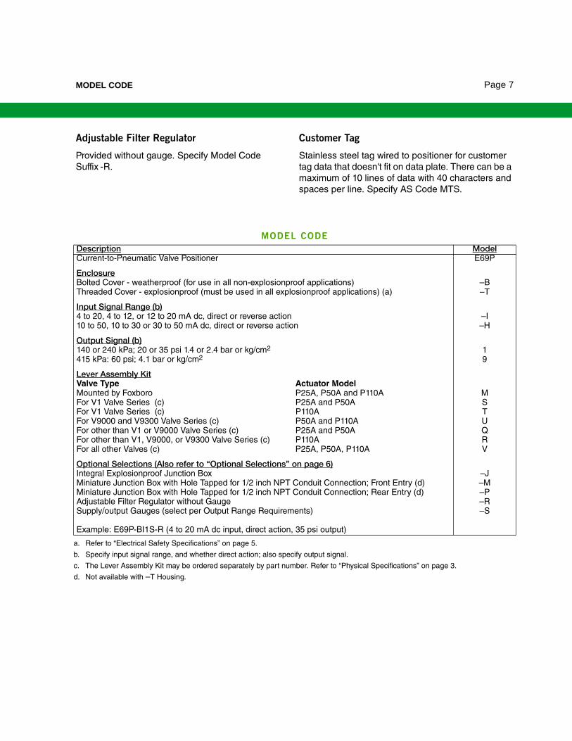
MODEL CODE
Description ModelCurrent-to-Pneumatic Valve Positioner E69P
EnclosureBolted Cover - weatherproof (for use in all non-explosionproof applications) –BThreaded Cover - explosionproof (must be used in all explosionproof applications) (a)
a. Refer to “Electrical Safety Specifications” on page 5.
–T
Input Signal Range (b)
b. Specify input signal range, and whether direct action; also specify output signal.
4 to 20, 4 to 12, or 12 to 20 mA dc, direct or reverse action –I10 to 50, 10 to 30 or 30 to 50 mA dc, direct or reverse action –H
Output Signal (b)140 or 240 kPa; 20 or 35 psi 1.4 or 2.4 bar or kg/cm2 1415 kPa: 60 psi; 4.1 bar or kg/cm2 9
Lever Assembly KitValve Type Actuator ModelMounted by Foxboro P25A, P50A and P110A MFor V1 Valve Series (c) P25A and P50A
c. The Lever Assembly Kit may be ordered separately by part number. Refer to “Physical Specifications” on page 3.
SFor V1 Valve Series (c) P110A TFor V9000 and V9300 Valve Series (c) P50A and P110A UFor other than V1 or V9000 Valve Series (c) P25A and P50A QFor other than V1, V9000, or V9300 Valve Series (c) P110A RFor all other Valves (c) P25A, P50A, P110A V
Optional Selections (Also refer to “Optional Selections” on page 6)Integral Explosionproof Junction Box –JMiniature Junction Box with Hole Tapped for 1/2 inch NPT Conduit Connection; Front Entry (d)
d. Not available with –T Housing.
–MMiniature Junction Box with Hole Tapped for 1/2 inch NPT Conduit Connection; Rear Entry (d) –PAdjustable Filter Regulator without Gauge –RSupply/output Gauges (select per Output Range Requirements) –S
Example: E69P-BI1S-R (4 to 20 mA dc input, direct action, 35 psi output)

Page 8 DIMENSIONS—NOMINAL
DIMENSIONS—NOMINAL
E69P — EXPLOSIONPROOF CONSTRUCTION
mmin
102
4.0
38
1.5
150
6.0
ALLOW 102 mm (4.0 in)
FOR REMOVAL OF COVER
0.312
YOKE
MOUNTING
STUDS
124
4.9
150
6.0
EXPLOSIONPROOF
CONSTRUCTION
INDICATING GAUGES (OPTIONAL)AIR OUTPUT CONNECTION
TAPPED FOR 1/4 NPT
167
6.6
290
11.4
85
3.4
TAMPER RESISTANT CLAMP,
LD-E VERSION ONLY
THREADED HOLE (2)
ASA 0.312-18 UNC x 0.44 in DEEP
ZERO ADJUSTMENT SCREW
ALLOW 150 mm (6.0 in) CLEARANCE
FOR ZERO ADJUSTMENT
1/8 NPT PLUGELECTRICAL INPUT CONNECTION
TAPPED FOR 1/2 in CONDUIT FITTING
148
5.9
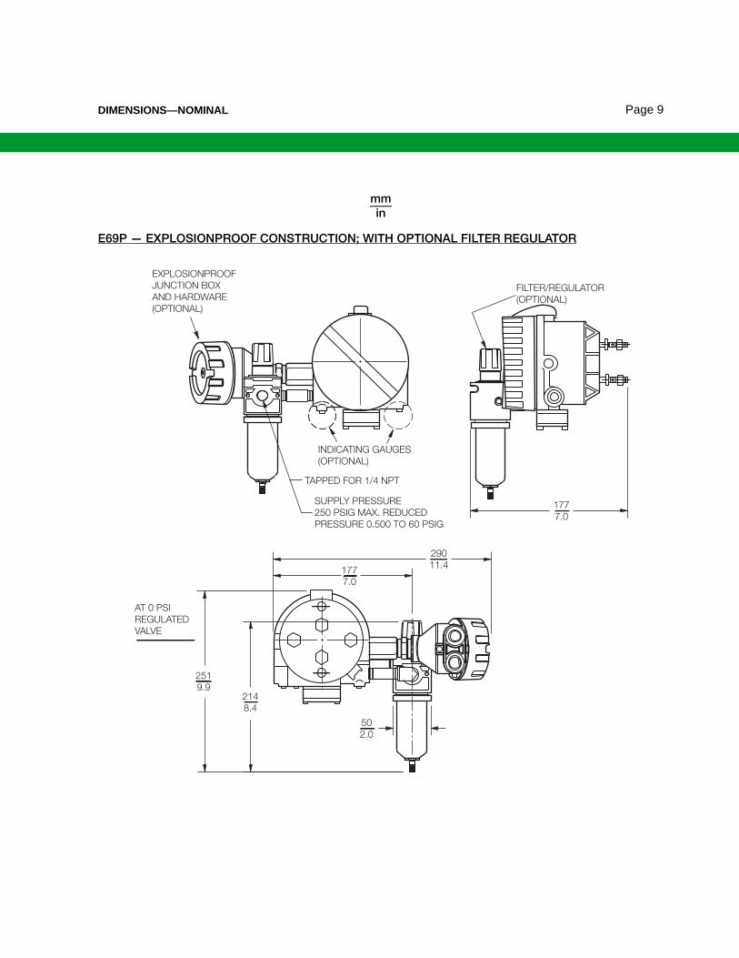
DIMENSIONS—NOMINAL Page 9
E69P — EXPLOSIONPROOF CONSTRUCTION; WITH OPTIONAL FILTER REGULATOR
mmin
AT 0 PSI
REGULATED
VALVE
EXPLOSIONPROOF
JUNCTION BOX
AND HARDWARE
(OPTIONAL)
INDICATING GAUGES
(OPTIONAL)
177
7.0
290
11.4
TAPPED FOR 1/4 NPT
SUPPLY PRESSURE
250 PSIG MAX. REDUCED
PRESSURE 0.500 TO 60 PSIG
FILTER/REGULATOR
(OPTIONAL)
177
7.0
50
2.0
251
9.9214
8.4

Page 10 DIMENSIONS—NOMINAL
E69P — WEATHERPROOF CONSTRUCTION; WITH OPTIONAL MINIATURE JUNCTION BOX
mmin
1405.6
582.3
381.5
642.5
1485.9
1244.9
1606.3
893.5
®
MINIATURE JUNCTION BOX (OPTIONAL)FRONTENTRYSHOWN**
0.312-18YOKEMOUNTINGSTUDS
AIR SUPPLYCONNECTIONTAPPED FOR1/4 NPT
WEATHERPROOF CONSTRUCTIONINDICATING GAUGE(OPTIONAL)
AIR OUTPUTCONNECTIONTAPPED FOR1/4 NPT
**CONNECTION OPTIONS
1/2 NPT CONDUIT, FRONT ENTRY -M1/2 NPT CONDUIT, REAR ENTRY -P
PG11 CABLE, FRONT ENTRY MB-APG11 CABLE, REAR ENTRY MB-DPG13.5 CABLE, FRONT ENTRY MB-BPG13.5 CABLE, REAR ENTRY MB-EM20 THREADED HOLE, FRONT ENTR MB-CM20 THREADED HOLE, REAR ENTRY MB-F
MODEL CODEOPTIONAL SELECTION
AS REFERENCEOPTIONAL SELECTION

NOTES Page 11
NOTES

Page 12
ORDERING INSTRUCTIONS
OTHER FOXBORO PRODUCTS
1. Model Number
2. Specific Input Signal (for Code I and Code H)
3. Positioner Action (Direct or Reverse)
4. Electrical Classification Code
5. Lever Assembly Kit - from Model Code or Physical Specifications section
5. Optional Selections - from Model Number and Optional Selections section
6. Tag and Application
The Foxboro product lines offer a broad range of measurement and instrument products, including solutions for pressure, flow, analytical, temperature, positioning, controlling, and recording.
For a list of these offerings, visit our web site at:
www.fielddevices.foxboro.com
Invensys Systems, Inc.10900 Equity DriveHouston, TX 77041United States of Americahttp://www.invensys.com
Global Customer SupportInside U.S.: 1-866-746-6477Outside U.S.:1-508-549-2424Website: http://support.ips.invensys.com
Copyright 1977-2015 Invensys Systems, Inc. All rights reserved.
Invensys, Foxboro, and I/A Series are trademarks of Invensys Limited, its subsidiaries, and affiliates. All other trademarks are the property of their respective owners.
Invensys is now part of Schneider Electric.
0115
nhon.pham
Stamp