Field Demonstration of CO 2 Miscible Flooding in the Lansing-Kansas City Formation, Central Kansas...
26
of CO 2 Miscible Flooding in the Lansing- Kansas City Formation, Central Kansas Alan P. Byrnes (KGS, PM- BP1) Class II Revisited DE-AC26- 00BC15124 Murfin Drilling Co. G. Paul Willhite (TORP, 2&3)
-
Upload
hayden-stanwick -
Category
Documents
-
view
213 -
download
1
Transcript of Field Demonstration of CO 2 Miscible Flooding in the Lansing-Kansas City Formation, Central Kansas...

Field Demonstration of CO2 Miscible Flooding
in the Lansing-Kansas City Formation, Central Kansas
Alan P. Byrnes (KGS, PM-BP1)
Class II Revisited DE-AC26-00BC15124
Murfin Drilling Co.
G. Paul Willhite (TORP, 2&3)

Central Kansas CO2 Pilot Overview
• Producibility Problem
• Central Kansas Resource Target
• Project Overview
• Pilot Site
• Demonstration Site Characteristics
• Present Status
• Producibility Problem
• Central Kansas Resource Target
• Project Overview
• Pilot Site
• Demonstration Site Characteristics
• Present Status

Kansas Oil Production History6.6 Billion Barrels to Date
Kansas Geological SurveyKansas Geological Survey
Gorham Oil Field –1928(Walters, 1991)
Producibility Problems• Primary producibility problem is that the
reservoirs have been depleted by effective waterflood
• Require technology that can mobilize residual oil
• Uncertainty in effectiveness of CO2 flooding process for central Kansas reservoir conditions
• No present economic supply of CO2 to Central Kansas
• Primary producibility problem is that the reservoirs have been depleted by effective waterflood
• Require technology that can mobilize residual oil
• Uncertainty in effectiveness of CO2 flooding process for central Kansas reservoir conditions
• No present economic supply of CO2 to Central Kansas

Central Kansas Oil Production
Kansas Total
6.6 Billion
Central Kansas Uplift Total
2.4 Billion
Kansas Total
6.6 Billion
Central Kansas Uplift Total
2.4 Billion
Arbuckle1,629 MMBO
L-KC613 MMBO
Mississippian53 MMBO
Shawnee73 MMBO
Ten County Central Kansas Uplift Production
LKC Pilot
Kansas Geological SurveyKansas Geological Survey

Purpose of Demonstration
• Determine the technical and economic feasibility of using CO2 miscible flooding to recover residual and bypassed oil in LKC shallow shelf carbonates.
• Develop reservoir data for the LKC and Hall-Gurney for other floods
• Develop an understanding of operating costs and operating experience for CO2 miscible flooding in Lansing-Kansas City reservoirs and central Kansas
• Prove up process and resource base to bring a pipeline in to central Kansas

General Demonstration Tasks
• Characterize the reservoir• Model the flood using reservoir simulation• Drill new injector for demonstration site• Design and construct facilities, rework wells, and
perform preliminary injection/connectivity tests• Implement the planned flood (BP2)• Monitor the flood process (BP2 & BP3)
BP1

Comparison Summary of Project Costs
Original 10+ acre
Total Project $5.40 $4.42CO2 Purchase & Transport $2.00 $0.87Research, Technology Transfer $1.50 $1.70Capital Costs (wells, etc.) $1.10 $0.92Operations $0.80 $0.93
FundingShell CO2 Company Inc. $1.63Kinder-Morgan CO2 Company LP $0.25US Energy Partners / ICM Inc. $0.38MV Energy LLC $0.83
Murfin Drilling Partnership $0.90U.S Department of Energy $1.89 $1.70University of Kansas $0.94 $1.00State of Kansas (KDOCH) $0.10 $0.19
Costs (millions $)

Pilot Site Located in Largest LKC Field: Hall-Gurney
Pilot Site Located in Largest LKC Field: Hall-Gurney
55 MMBO
19 MMBO

Evolution of Flood Pattern

10+Acre Pattern
• 10+ acre, four-spot
• 1 CO2 injector
• 3 Producers
• 2 Containment Water Injectors
• 0.29 BCF CO2 injected-WAG
• 6 year operating life
• 28,000 BO estimated recovery
• 10+ acre, four-spot
• 1 CO2 injector
• 3 Producers
• 2 Containment Water Injectors
• 0.29 BCF CO2 injected-WAG
• 6 year operating life
• 28,000 BO estimated recovery
Originally CO2 was being trucked 200 miles from Guymon,OK
CO2 now being supplied by USEP ethanol plant only 7 miles away in Russell, KS

Colliver-Carter CO2 Injection Well drilled October 2000 (view from the SE corner of the Colliver lease
Colliver 13

Carter-Colliver #1 CO2 I Coring
Conventional core in upper 2 feet (right) was successful. High-pressure core (above) was disaggregated in porous intervals

(Scholle & James, 1995)
Modern Ooid Shoal,Great Bahama Banks
LKC Oomoldic Limestone pervasive across KS Shelf
and similar worldwide
L-KC CO2 I #1 2903 ft
•Early pore cementation•Ooid dissolution•Crushing

Carter-Colliver #1 CO2 I
0102030
Neutron-Density
Porosity %
Neutron-Density
Porosity %Gamma RayGamma Ray
LansingLansing“A”“A”
“B”“B”
“C”“C”
“D”“D”
“E”“E”
Conventional CoreConventional Core
10’ Pressure Cores10’ Pressure Cores807
441
RF
T P
ress
ures
IPP 1BO + 50 BWPD, NatIPP 1BO + 50 BWPD, Nat
Kansas Geological SurveyKansas Geological Survey
2888
2890
2892
2894
2896
2898
2900
2902
2904
2906
2908
0.001 0.01 0.1 1 10 100 1000
Permeability (md)
De
pth
(ft
)
CO2 #1 Plug K
Colliver #1 Whole Core K
24 Layer
CO2 #1 Whole Core K

Water Saturations in Carter-Colliver CO2 I#1
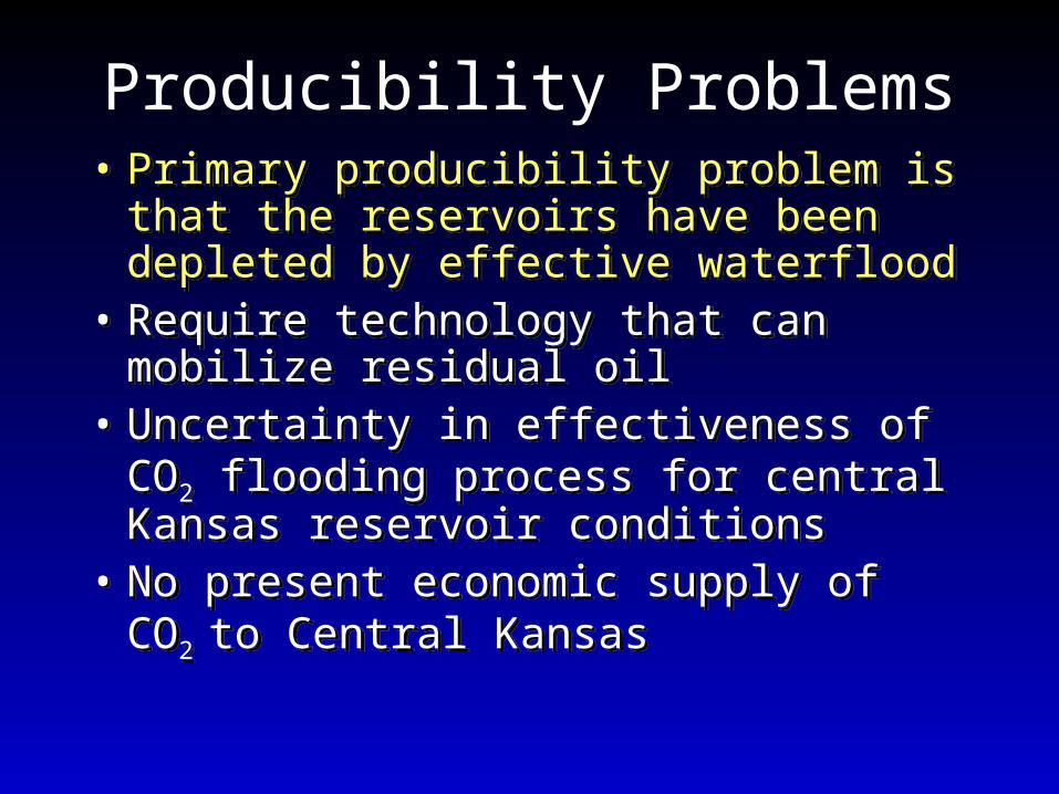
Minimum Miscibility Pressure in Hall-Gurney LKC
0
10
20
30
40
50
60
70
80
90
100
1000 1050 1100 1150 1200 1250 1300 1350
Average Slimtube Pressure (psig)
Slim
tub
e R
eco
very
(%
)
API = 37.5o-38.4oAPI = 37.5o-38.4o
TORP

Demonstration Site Description• Lansing-Kansas City “C”
zone• Oomoldic Limestone• Depth – 2,900 feet• Net thickness - 15 feet• Porosity – 24-30%• Permeability – 10-200 md• Estimated residual oil
saturation after waterflooding - >30%
• Initial Pressure - ~1250 psig
• Primary Drive - Solution Gas
• Lease location- – Colliver: E/2SW/4&SE/4
Sec 28-14S-13W
• 10+ acre, four-spot• 1-injector, 3-producers, 2-
containment injectors• Estimated Lease Primary
Recovery – 23% OOIP• Estimated Lease
Secondary Recovery – 27% OOIP
• Estimated Site CO2 Recovery 23,000-36,000 BO

Model Characteristics• 6 & 13 layer models (15 ft thick
reservoir)• Grid blocks : 110’x110’ block size• Models :
– Black oil for history match of primary & secondary production
– Six pseudocomponent, fully compositional model for CO2 simulation
• Single initial average (pseudo-) water saturation for each layer
• Pseudo-relative permeability curves and capillary pressure curves for each layer

Reservoir Simulation of 10+acre CO2 Flood182 days 367 days 762 days
1097 days 3714 days
Tertiary Oil
Recovery Project
Layer 2
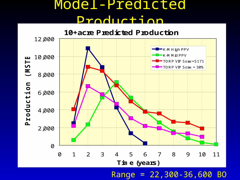
Model-Predicted Production10+acre Predicted Production
0
2,000
4,000
6,000
8,000
10,000
12,000
0 1 2 3 4 5 6 7 8 9 10 11
Time (years)
Pro
du
cti
on
(M
ST
B/Y
r)
K-M High PPV
K-M Mid PPV
TORP VIP Sorw=S171
TORP VIP Sorw = 30%
Range = 22,300-36,600 BO

CO2 Supply and Sequestration
•Multiple Goals
•Prove viability of process and extend pipeline from Guymon, OK to central KS
•Perform CO2 sequestration utilizing CO2 from ethanol plant and demonstrate linked-systems

Summary•Kansas EOR potential using CO2 flooding may exceed 200-500 MMBO – if potential proves up, the LKC and Arbuckle in central KS have sufficient resource to support a pipeline
•Partners in Lansing-Kansas City Demonstration Flood
•Murfin Drilling Company, Inc.
• Kinder-Morgan CO2 Co. LP
•US Energy Partners LLC/ICM
•U.S. Department of Energy
•KGS and TORP, University of Kansas
•Kansas Department of Commerce & Housing
•Reservoir Characterization and Simulation are Complete
•New CO2 Injector– being prepared for initial water injection
•Producers (#12, #13, #16) being reworked
•CO2 being supplied from ethanol plant and in-kind contribution
•Initial CO2 injection begins in 2nd quarter 2003

www.kgs.ukans.edu/ERC/CO2Pilot
Read more about it

Sunrise on CO2
flooding in Kansas
Sunrise on CO2
flooding in Kansas


![Dichotomous role of pancreatic HUWE1/MULE/ARF-BP1 in ... · ubiquitin protein ligase (HUWE1 [also known as MULE or ARF-BP1]) isa criticalregulator ofp53-dependent apoptosis. However,](https://static.fdocuments.in/doc/165x107/5f09e4a87e708231d429019f/dichotomous-role-of-pancreatic-huwe1mulearf-bp1-in-ubiquitin-protein-ligase.jpg)