Field Bus Control - newlift.de · Commissioning the car ... Risk of injuries when lifting and...
76
Installation & Commissioning Field Bus Control
Transcript of Field Bus Control - newlift.de · Commissioning the car ... Risk of injuries when lifting and...

Installation & Commissioning
Field Bus Control

Publisher NEW LIFT Steuerungsbau GmbH
Adi-Maislinger-Straße 12D-81373 München
Tel.: +49 (0) 89 / 74 35 44 - 0Fax: +49 (0) 89 / 769 34 85
Doc. No. FST_MIA.DE10/98
Date of issue 10/98
Copyright © 1998, NEW LIFT Steuerungsbau GmbH
All rights, including those of copying or of reproducing parts of this description and of the translation are reserved by the publisher.
No part of this description may be reproduced in any form or copied with an electronic replication system, without the written permission of the publisher.
FST_MIA.DE10/98

Table of contents
1 About this manual .............................................................................................. 5
1.1 General information .................................................................................................. 5
1.2 Signs and symbols employed .............................................................................. 6
2 General safety provisions ............................................................................. 9
2.1 Qualifications of the installing engineer .......................................................... 9
2.2 Residual dangers ..................................................................................................... 10
2.3 Safety provisions ..................................................................................................... 10
3 Assembly work ................................................................................................... 13
3.1 Installation sequence ............................................................................................. 13
3.2 Bus Plan ...................................................................................................................... 15
3.3 Scope of delivery ..................................................................................................... 16
3.4 Control cabinet ......................................................................................................... 18Installing the control cabinet ............................................................................................ 18Connecting the control cabinet ........................................................................................ 19Starting up the control cabinet......................................................................................... 20Technical details.............................................................................................................. 21
3.5 Car components ....................................................................................................... 25Installation locations of the car components.................................................................... 25Installing car components................................................................................................ 26Connecting car components............................................................................................ 27Commissioning the car components ............................................................................... 28Technical details - FPM car operating panel module ..................................................... 29Technical details - FSM car control module .................................................................... 31
3.6 Installing and connecting the trailing ribbon cable .................................. 33
3.7 The installation run ................................................................................................. 35Connecting the LON bus ................................................................................................. 37Installing zone switches and magnets ............................................................................. 38Installing and setting the linear copying control............................................................... 40
FST_MIA.DE10/98 3

Table of contents
4 Commissioning the FST Control ........................................................... 43
4.1 Commissioning sequence ................................................................................... 43
4.2 User interface of the FST Control ..................................................................... 44The display ...................................................................................................................... 45The keyboard................................................................................................................... 47The LEDs......................................................................................................................... 48
4.3 Commissioning the linear copying control .................................................. 49Checking the direction of rotation of the absolute value encoder. ................................... 49Checking flush position with A6 Safety Monitoring Device .............................................. 50Checking flush position with A6 Safety Monitoring Device .............................................. 51
4.4 Carrying out a calibration drive ......................................................................... 53
4.5 Commissioning the A6 Safety Monitoring Device ..................................... 57
4.6 Setting control options .......................................................................................... 58Crawl drive....................................................................................................................... 58Password ......................................................................................................................... 58Door times ....................................................................................................................... 59Group operation............................................................................................................... 60
5 Event and fault messages ........................................................................... 61
5.1 LED messages on the user interface .............................................................. 61
5.2 Error list ....................................................................................................................... 62
5.3 Event messages ....................................................................................................... 64
5.4 Error messages ........................................................................................................ 65
6 Terminal and pin assignment ................................................................... 69Trailing ribbon cable ........................................................................................................ 69LON bus........................................................................................................................... 72VSM preselection module................................................................................................ 72FSM car control module.................................................................................................. 72
7 Index ........................................................................................................................... 73
4 FST_MIA.DE10/98

1 About this manual
1 About this manual
Before installing and starting up the FST Control, you should carefully read this manual first. The instructions in Chapter 2 “General safety provisions” always take precedence. How to operate the FST Control is outlined in Chapter 4.2 “User interface of the FST Control”.
1.1 General information
This manual is intended to facilitate the assembly and commissioning of the FST Control and its components.
This assembly and operating manual contains important instructions for the safe and proper assembly and commissioning of the FST Control.
Observing them helps to:
- avoid dangers
- minimise repair costs and downtime
- increase the reliability and service life of the FST Control and the lift system.
In addition to this assembly and operation manual, the valid accident prevention and environmental protection regulations in the respective country and locality must be observed.
Only those sub-assemblies supplied by NEW LIFT are described in this manual.Information about components of the control system not produced and supplied by NEW LIFT can be obtained from the user documentation provided by the respective manufacturer or supplier.
FST_MIA.DE10/98 5

1 About this manual
1.2 Signs and symbols employed
The following signs and symbols have been used for operational instructions:
Symbols ➤ Activity symbol:The activities described after this sign should be carried out in the prescribed sequence.
✔ Outcome symbol:The outcome of an activity is described.
+ Key combination :Press the linked keys simultaneously.
Warning signs General danger point
This sign appears before activities where personal injuries may arise due to various causes.
Risk of crushing injuries
This sign appears in front of activities where there is a danger of receiving crushing injuries.
Danger of falling
This sign appears in front of activities where there is a danger of falling.
Suspended load
This sign appears in front of activities where there is a danger of direct impact from a falling load.
6 FST_MIA.DE10/98

1 About this manual
High voltage
This sign appears in front of activities where there is a danger of an electric shock, with possibly fatal consequences.
Material damage
The instructions provided here are intended to prevent any material damage to sub-assemblies and devices.
FST_MIA.DE10/98 7

1 About this manual
8 FST_MIA.DE10/98

2 General safety provisions
2 General safety provisions
All the most important safety provisions and regulations are compiled in the Chapter 2 “General safety provisions”.
Anybody who is assigned to work on the installation and commissioning of the FST Control, must have read this chapter and put its provisions into practice.
Over and above any safety provisions specified in this manual, the laws, regulations, guidelines and standards in force in the respective country should be observed.
2.1 Qualifications of the installing engineer
The installing engineer must:
- be 18 years of age or older (exception: trainees of 16 years or older, under the constant supervision of a master craftsman).
- be able to carry out first aid.
- know and be able to implement the fire and explosion protection regulations applicable for his work area.
- be able to recognise, avoid and protect himself against all the dangers arising in conjunction with his work in the lift shaft and in the operating areas.
- be able to identify and rectify all irregularities and faults arising during installation and operation of an lift system.
- understand and be able to apply the technical basis of the mode of operation of electrical controls and drive systems and their operating requirements.
All installation and commissioning work on the electrical and electronic components of the FST Control are to be carried out under the direction and supervision of a qualified electrician.
In Germany, someone is defined as a qualified electrician, who due to his technical training, knowledge and experience and acquaintance with the relevant provisions, is able to evaluate the work assigned to him and to identify the possible dangers (UVV, VGB 4, §2 (3)).
FST_MIA.DE10/98 9

2 General safety provisions
2.2 Residual dangers
Danger for personnel Risk of electrocution on touching parts under voltage during work on the electrical installations.
Risk of fatal injuries due to falling down the lift shaft.
Risk of injuries when lifting and transporting the switch cabinet if this falls or tips over.
Risk of dangers to persons, who are in the lift shaft when the car is in motion.
Risk of injuries due to unforeseen car movements.
Risk of material damage Destruction of the FST Control and its electronics modules by short circuiting or excess loading.
2.3 Safety provisions
General information The instructions of the manufacturer and the information in this manual must be observed when the lift is being installed and commissioned.
The lift shaft must be secured against unauthorised access during installation and commissioning.
Sub-assemblies, devices and cables should be installed securely and permanently.
Loads should be transported with suitable aids (e.g. lift trucks, lifting gear etc.).
Sharp or pointed tools or other potentially dangerous objects may not be carried in clothing, unless protected by sufficient protective measures.
The consumption of alcohol and drugs before and during installation and commissioning is forbidden.
10 FST_MIA.DE10/98

2 General safety provisions
Documentation A copy of the installation and commissioning manual must be available to the installation engineer when the FST Control and its components are being installed and commissioned.
A copy of the installation and commissioning manual together with the circuit diagrams should always be kept in the switch cabinet on completion of commissioning.
The supplied circuit diagrams for the FST Control are binding. Alterations may only be made in consultation with NEW LIFT and should be documented in writing on the system.
The on-site test logs for the FST Control are retained by NEW LIFT.
Electro-technical work The regulations for setting up and operating electrical systems (VDE 0100) as well as the special guidelines of the local power utilities should be observed.
The prescribed spacings between the individual electrical assemblies should be observed.
Assembly work may only be carried out when the equipment is shut down and voltage-free.
Cables and lines should be provided with sufficient strain relief.
The neutral and ground lines should be separately routed.
A clockwise rotary field must be applied at the switch cabinet.
Working in the lift shaft If the car is being used as assembly platform, the regulations from VGB 35: “Bauaufzüge” (building elevators) apply for the whole lift system:
During work in the lift shaft, there must be unimpaired and continuous communication between the supervisor at the FST Control in the machine room and the workers.
““The components in the lift shaft must be arranged or secured so that persons who are in the lift shaft for inspection, maintenance or repair work purposes are not endangered.” (AufzV, Appendix 2.1.5)
The permitted load for the lift system may not be exceeded.
FST_MIA.DE10/98 11

2 General safety provisions
The prescribed overruns for the emergency limit switches in relation to the lift speed must be observed.
The emergency installations may not be activated during normal operation.
All emergency installations and braking systems must be checked before each shift for perfect functioning.
The car must be moved to the lowest resting position during breaks, the control switched off and the power supply permanently interrupted.
Assembly and operation are prohibited when other persons could be endangered.
Personnel must be protected against falling.
Personal safety equipment forthe installing engineers
- Eye protection
- Safety boots
- Hard hat
- Safety harness
- Clothing appropriate to the environmental conditions at the installation site
- Jewellery, wrist watches and suchlike may not be worn.
Handlingelectronics modules
Keep the electronics modules in the supplied packing until installation.
Touch a grounded piece of metal before opening the packaging in order to electrically discharge your body.
All non-assigned bus inputs or outputs should be provided with a terminal resistance (terminator).
Disposal The packaging material is to be disposed of in an environmentally friendly way.
Hand in paper, plastic, metal and electronics components for recycling.
Adhesive residues should be disposed of in an environmentally responsible way in accordance with the appropriate laws and regulations.
12 FST_MIA.DE10/98

3 Assembly work
3 Assembly work
All the important information on the installation sequence, installation conditions and settings of the NEW LIFT components are described. Special features on-site could mean that deviations from the recommended installation sequence recommended below are necessary.
3.1 Installation sequence
NEW LIFT recommends the assembly work according to Fig. 3.1 on Page 14. First all those NEW LIFT components are installed, connected and set, which are required for commissioning the car. Once the car is ready, “installation runs” are made to install the NEW LIFT components in the shaft, such as linear copying control, LON bus and zone magnets. The FST Control is then commissioned (See Page 43).
FST_MIA.DE10/98 13

3 Assembly work
Fig. 3.1 Recommended installation sequence for NEW LIFT components
MIA010.abc
Check the scope of delivery
Commissioning the elevator car
Control cabinet installation / connection
Drive installation / connection
Safety monitoring device
installation /connection
Elevator car components
installation / connection
Linear copying control
installation / connection
Trailing ribbon cable installation / connection
Magnetic switch panel and zone magnets
installation / connection
(if available)
LON-Bus installation / connection
Commissioning of FST
Shaft doors installation / connection
Installation run
14 FST_MIA.DE10/98

3 Assembly work
3.2 Bus Plan
Each lift system consists of specific electronics modules and cables. NEW LIFT creates a bus plan for the configuration of each individual lift control, enclosed with the circuit documentation. All electronics modules and their connections are presented in the bus diagram with the associated LON bus cables. For each electronics module, its installation site, the associated bus and with LON bus cables, the respective length are all specified. Each electronics module is labelled. With this labelling, it is possible to unambiguously assign components with the bus plan.
Fig. 3.2 FST Control bus plan
FST_MIA.DE10/98 15

3 Assembly work
3.3 Scope of delivery
NEW LIFT components and documentation:
- Switch cabinet with integrated FST Control
- Electronics modules according to bus plan
- Ready-made LON bus cables according to the bus plan
- Ready-made trailing ribbon cable according to the bus plan
- Terminal resistances (terminators)
- FST manual (glued into switch cabinet)
- FST installation & commissioning manual
- Circuit diagrams
- Bus Plan
Check the scope of delivery Check the delivery of NEW LIFT components for completeness against the packing list. Simultaneously make a visual inspection of the delivered items for damage.
When unpacking the delivery, check against the bus plan:
- whether mechanical damage to the NEW LIFT components can be identified.
- whether the labelling of the NEW LIFT electronic assemblies agrees with the labelling on the bus plan.
- whether the LON bus cables and the trailing ribbon cable are of the lengths specified in the bus plan.
NOTE!
Electrostatic discharges, mechanical loading, dampness and dirt can damage or even destroy electronics modules.
➤ Keep the electronics module in the supplied packing until installation.
➤ Touch a grounded piece of metal before opening the packaging in order to electrically discharge your body.
16 FST_MIA.DE10/98
3 Assembly work
Claims for damageduring transport
If damage arises during transport, a claim must immediately submitted to the haulier.
Ordering NEW LIFT components separately
If NEW LIFT electronics modules or cables are missing, you should report this immediately to the NEW LIFT hotline. We will require the following information to ensure rapid processing:
- 8 digit NEW LIFT serial number, e.g.: FC980591(obtained from the bus plan)
- Name of the missing NEW LIFT components(obtained from the bus plan)
- Missing cable type and length(obtained from the bus plan)
- Your telephone/ FAX number or e-mail address for any queries
FST_MIA.DE10/98 17

3 Assembly work
3.4 Control cabinet
Installing the control cabinet
Transport the control cabinet to and install it at the planned installation site (see ”Technical details” on Page 21). The fixings depend on the nature of the installation site and the weight of the control cabinet and are to be selected by the installation engineer.
The planned installation site can only be changed in exceptional cases since it is unlikely that the ready-prepared cable lengths are sufficient. Please inform the NEW LIFT hotline so that a solution can be worked out.
DANGER!
The control cabinet may fall over during transport or installation.
Danger of limbs being crushed.
➤ Only transport and lift the control cabinet with suitable aids (e.g. lift truck, lifting gear etc.).
The personnel must have been instructed in the use of these aids and observe the special accident prevention rules applicable for them.
DANGER!
Electric shock or escaping gas due to holes drilled in supply lines.
Severe, possibly even fatal injuries.
➤ Ensure before starting work that no supply lines are routed through the installation site.
18 FST_MIA.DE10/98

3 Assembly work
Connecting the control cabinet
The cable diameters of the supply, drive and ground lines are determined by the load connected to the control cabinet and can be obtained form the enclosed circuit documents.
Equipotential bonding is to be carried out according to the valid electrical engineering regulations and specifications (VDE, DIN, EN and ISO), depending on the output load.
The neutral and ground lines should be routed separately!
All lines should be secured against be pulled out by adequate strain relief.
When attaching the trailing ribbon cable, the correct installation direction of the cable should be observed (see ”Assignment of terminals and plugs of the trailing ribbon cable to the modules” on Page 34).
DANGER!
Electric shock from electrically live lines and parts.
Severe, possibly even fatal injuries.
➤ Check and ensure voltage-free condition.
➤ Only carry out installation work on electrical components when they are switched off and voltage-free.
FST_MIA.DE10/98 19

3 Assembly work
Starting up the control cabinet
Check the following before switching on the FST Control:
- clockwise rotary field
- proper functioning of fuses
- proper functioning of control cabinet components
The display and operation of the FST Control is explained in Chapter 4.2 on Page 44.
Switching on the FST ➤ Turn on control cabinet at main switch.
➤ Turn on FST power supply circuit at the fuse.
✔ The FST Control is rebooted.
On completion of the booting procedure, 15 “✔” are briefly displayed on the bottom line and then switches to the standard display.
If 6$)(7<�&&7�&/26(' is not displayed on line A, there is a break in the safety monitoring device wiring or it is faulty and has to be checked, extended or repaired.
If ,167$//$7,21�02'(� is not indicated in line B, then installation mode should be set.
➤ Select 0$,1�0(18���,QVWDOODWLRQ���,QVWDOODWLRQ�PRGH.
➤ Select <(6.
➤ Confirm selection with (.
✔ ,QVWDOODWLRQ�PRGH is set.
Switching off the FST ➤ Turn off the FST power supply circuit at the fuse.
6$)(7<�&&7�&/26('
,QVWDOODWLRQ�PRGH
!$;�������������������������������
�����������������������������������������
20 FST_MIA.DE10/98

3 Assembly work
Technical details
Output load The output load depends on the drive load and lifting height of the lift.
4 kW / 16 A - 46 kW / 120 A
Weight The weight of the control cabinet depends on its size and the output load.
50 - 200 kg
Safety clearances The safety clearances specified in the “Technical Rules for Elevators” are to be observed, even when the control cabinet door is open.
FST_MIA.DE10/98 21
3 Assembly work
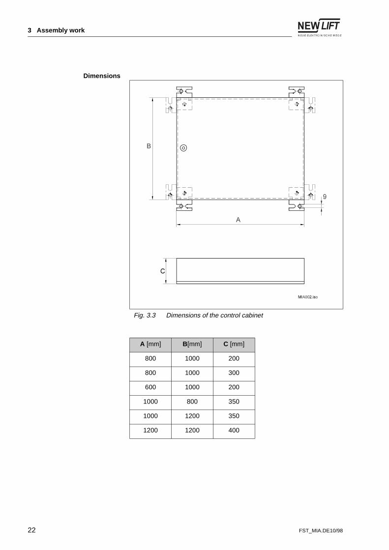
Dimensions
Fig. 3.3 Dimensions of the control cabinet
A [mm] B[mm] C [mm]
800 1000 200
800 1000 300
600 1000 200
1000 800 350
1000 1200 350
1200 1200 400
22 FST_MIA.DE10/98

3 Assembly work
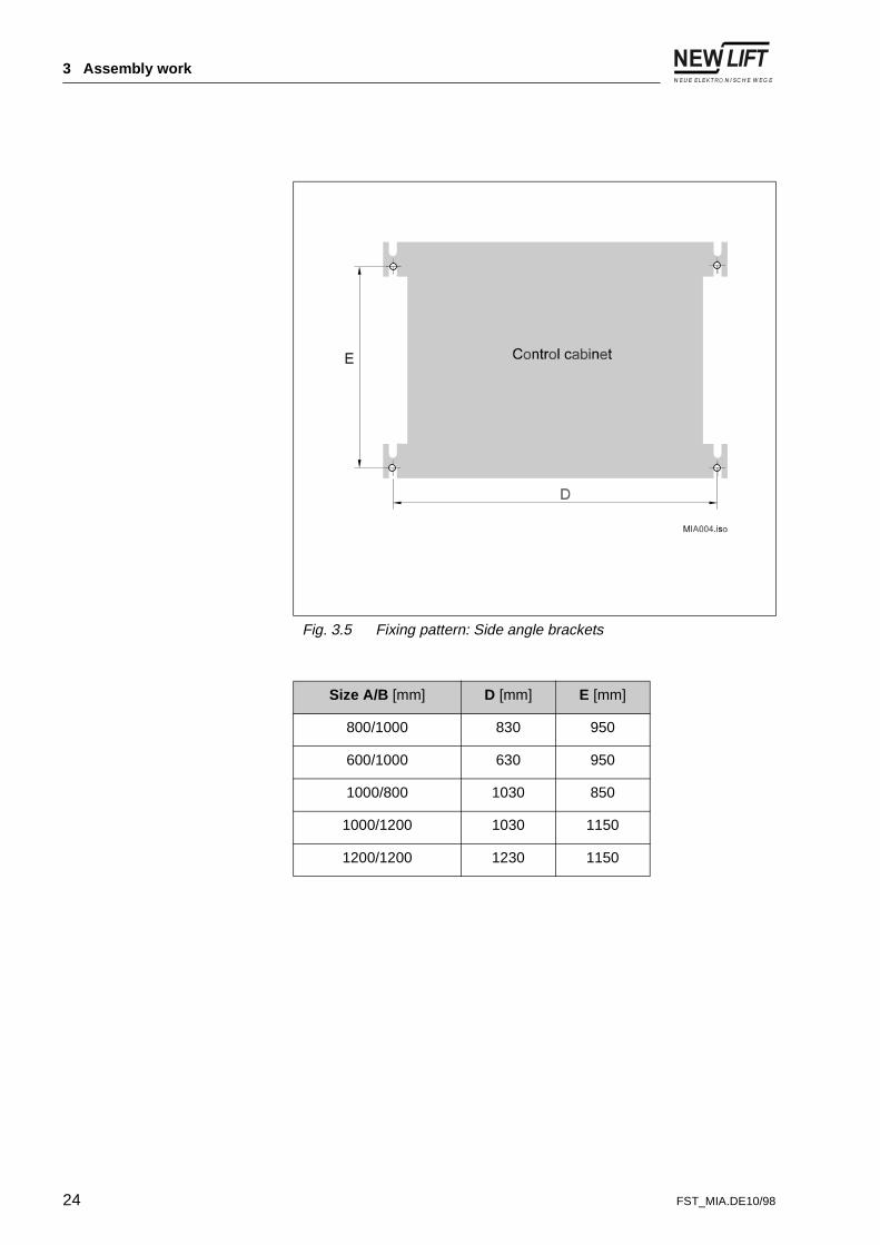
Installation The scope of delivery includes the angle brackets but not the actual fixings. The diameter of the boreholes is determined by the size of the fixing screws selected.
Fig. 3.4 Fixing pattern: Top /bottom angle brackets
Size A/B [mm] D [mm] E [mm]
800/1000 780 1030
600/1000 580 1030
1000/800 980 830
1000/1200 980 1230
1200/1200 1180 1230
FST_MIA.DE10/98 23
3 Assembly work
Fig. 3.5 Fixing pattern: Side angle brackets
Size A/B [mm] D [mm] E [mm]
800/1000 830 950
600/1000 630 950
1000/800 1030 850
1000/1200 1030 1150
1200/1200 1230 1150
24 FST_MIA.DE10/98
3 Assembly work
3.5 Car components
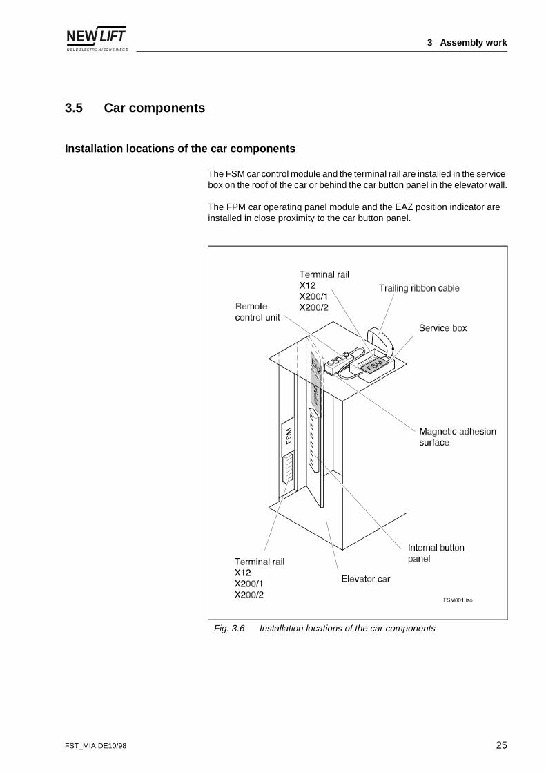
Installation locations of the car components
The FSM car control module and the terminal rail are installed in the service box on the roof of the car or behind the car button panel in the elevator wall.
The FPM car operating panel module and the EAZ position indicator are installed in close proximity to the car button panel.
Fig. 3.6 Installation locations of the car components
FST_MIA.DE10/98 25

3 Assembly work
Installing car components
DANGER!
Fitting engineers and unauthorised persons could fall down the lift shaft.
Severe, possibly even fatal injuries.
➤ Cordon off access to shaft.
➤ Only carry out work on or in the lift shaft with suitable protection (e.g. safety harnesses, scaffolding, etc.).
➤ Observe the accident prevention regulations for operating building lifts and assembly platforms.
DANGER!
Parts or equipment falling down the shaft.
Severe, possibly even fatal injuries.
➤ Cordon off access to shaft.
➤ Remove all loose objects from the lift shaft before starting installation work.
DANGER!
Objects projecting into the lift shaft.
Severe, possibly even fatal injuries.
➤ Remove all foreign objects and installation aids which are no longer required from the lift shaft.
NOTE!
Electrostatic discharges, mechanical loading, dampness and dirt can damage or even destroy electronics modules.
➤ Touch a grounded piece of metal before adjusting or examining the electronics modules, in order to electrically discharge your body.
26 FST_MIA.DE10/98
3 Assembly work
Installing electronic modules on the
car
The following electronics modules are ready installed:
- the FPM car operating panel module in the car button panel
- the FSM car control module in the service box.
The EAZ position indicators are installed at the planned location.
Setting electronic modules
The electronics modules are adapted to the respective lift system by means of plug-in jumpers. Settings are made ex-works and must be checked during installation:
- Plug-in jumpers for FPM car operating panel module(See Page 30)
- Plug-in jumpers for FSM car control module(See Page 31)
Connecting car components
Connecting electronic components
The electronics modules are connected according to the bus plan (see Page 15) and unassigned bus inputs or outputs for the electronics modules are terminated with a terminal resistance (terminator).
Non-terminated, open bus inputs or outputs can result in malfunctioning of the FST Control.
Connecting the remotecontrol unit
The remote control unit is attached by the magnetic surface to the metal part of the car roof (see Page 25).
The remote control unit is connected to the FSM:X12 car control module and the X200/3 terminal block.
The remote control unit remains attached to the car roof after commissioning.
Connecting door control Connect the door control to the FSM car control module.
With doors without limit switches:
The limit switch inputs on the FSM car control module must be bridged (see Page 32).
FST_MIA.DE10/98 27

3 Assembly work
Connecting the trailing ribbon cable
Connect the trailing ribbon cable to the FSM car control module and the terminal blocks (see Page 34).
Note the direction of installation of the trailing ribbon cable!
Connecting the car button panel
Connect the 9 pin D-SUB plug for the car emergency lighting and the emergency call to the FSM:X3 car control module.
Commissioning the car components
Requirements - car installation is concluded
- trailing ribbon cable is connected
- safety monitoring device is active
- non-assigned bus inputs or outputs are terminated
- the lift control is not in ,QVSHFWLRQ or $X[LOLDU\ mode.
DANGER!
Risk of electric shocks from electrically live lines and parts.
Severe, possibly even fatal injuries.
➤ Check and ensure voltage-free condition.
➤ Only carry out installation work on electrical components when they are switched off and voltage-free.
NOTE!!
Electronic components can be destroyed by defective, reversed or incorrectly connected plugs.
➤ Check plugs for any mechanical damage.
➤ Do not modify ready-made plugs!
➤ Attach loose or pulled out wires according to the circuit diagrams.
28 FST_MIA.DE10/98

3 Assembly work
Checking the EMERGENCYSTOP remote control unit
➤ Pull the EMERGENCY STOP SWITCH next to the remote control unit.
✔ (0(5*(1&<�6723 appears in line A of the FST display.
If this is not the case, there is an installation fault which must be rectified.
➤ Release EMERGENCY STOP SWITCH lock .
✔ 6DIHW\�&&7�&ORVHG appears in line A of the FST display.
Checking cage functions All cage functions must be checked with the aid of the circuit diagram.
Technical details - FPM car operating panel module
The FPM car operating panel module is supplied by the manufacturer of the panel board, ready assembled and wired.
Free plug-in jumpers Not plugged in:
- J1 (service plug-in jumper)
- J2 (no function at present).
Fig. 3.7 Plug-in jumpers for FPM car operating panel module
FST_MIA.DE10/98 29

3 Assembly work
Setting the doors The car doors are set with the plug-in jumpers JT1 and JT2.
Conforming a carto individual operation
Conforming a carto group operation
If several FSTs and cars are co-ordinated by one GST Group Control (see the “GST manual”), the respective car is assigned to its FST Control via the plug-in jumpers JK1, JK2 and JK4.
The car assignment with the FSM car control module and the FPM car operating panel module must be identical.
Setting JT1 JT2
Door A open open
Door B plugged in open
Door C open plugged in
not applicable plugged in plugged in
Setting JK4 JK2 JK1
FST A open open open
Setting JK4 JK2 JK1
FST A open open open
FST B open open plugged in
FST C open plugged in open
FST D open plugged in plugged in
FST E plugged in open open
FST F plugged in open plugged in
FST G plugged in plugged in open
FST H plugged in plugged in plugged in
30 FST_MIA.DE10/98

3 Assembly work
Technical details - FSM car control module
Free plug-in jumpers Not plugged in:
- J1 (service plug-in jumper)
- J2 (no function at present).
Setting the doors The car doors are adjusted with the plug-in jumpers JT1 and JT2.
Fig. 3.8 Plug-in jumpers and plugs on the FSM car control module
Setting JT1 JT2
Door A or Door A & B open open
Door C plugged in open
not applicable open plugged in
not applicable plugged in plugged in
FST_MIA.DE10/98 31

3 Assembly work
Conforming the carto individual operation
Conforming the carto group operation
If several FSTs and cars are administered by one GST Group Control (see the “GST manual”), the respective car is assigned its FST Control via the plug-in jumpers JK1, JK2 and JK4.
The car assignment for the FSM car control module and the FPM car operating panel module must be identical.
Setting doors without limitswitches
If doors without limit switches are used, the door relay enabling must be bypassed.
The following are bypassed:
- X8:1 with X8:2
- X8:3 with X8:4
- X9:1 with X9:2
- X9:3 with X9:4.
The jumpers must be long and clearly visible!
Setting JK4 JK2 JK1
FST A open open open
Setting JK4 JK2 JK1
FST A open open open
FST B open open plugged in
FST C open plugged in open
FST D open plugged in plugged in
FST E plugged in open open
FST F plugged in open plugged in
FST G plugged in plugged in open
FST H plugged in plugged in plugged in
32 FST_MIA.DE10/98

3 Assembly work
3.6 Installing and connecting the trailing ribbon cable
The suspension brackets for the trailing ribbon cable are installed in the shaft and the trailing ribbon cable is then laid.
Note:
- the turning point of the trailing ribbon cable is half way up the shaft
- the outer and inner side of the trailing ribbon cable.
The trailing ribbon cable is connected to the NEW LIFT components on the car and the control (see Page 34).
Technical details
Fig. 3.9 Example of installation of trailing ribbon cable in the shaft
FST_MIA.DE10/98 33

3 Assembly work
Fig. 3.10 Assignment of terminals and plugs of the trailing ribbon cable to the modules
34 FST_MIA.DE10/98

3 Assembly work
3.7 The installation run
In order to install the remaining shaft components - the LON bus, zone switches / magnets and the linear copying control; installation runs can be carried out with the aid of the remote control unit on the car roof or the auxiliary control in the control cabinet.
During the installation run, the shaft components are installed from the roof of the car. The car is controlled by the installing engineer on the car roof by means of the remote control unit. When the inspection control is active, all other commands are suppressed and it should be switched off before each installation run.
Before an installation run is undertaken, the specified conditions must be fulfilled and the following safety instructions and the applicable accident prevention regulations must be observed.
Requirements - FST Control is in ,QVWDOODWLRQ�PRGH (see Page 20)
- FST Control is in ,QVSHFWLRQ or $X[LOLDU\ mode.
- safety monitoring device is operational
- safety catch checked for proper functioning
- car is operational
- drive is operational
- knowledge of all dangers arising in the shaft and how to avoid them
- emergency stop button of the remote control unit tested for proper functioning.
DANGER!
Fitting engineers and unauthorised persons could fall down the lift shaft.
Severe, possibly even fatal injuries.
➤ Cordon off access to shaft.
➤ Only carry out work on or in the lift shaft with suitable protection (e.g. safety harnesses, scaffolding etc.).
➤ Observe the accident prevention regulations for operating building lifts and assembly platforms.
FST_MIA.DE10/98 35

3 Assembly work
DANGER!
Parts or equipment falling down the shaft.
Severe, possibly even fatal injuries.
➤ Cordon off access to shaft.
➤ Remove all loose objects from the lift shaft before starting installation work.
DANGER!
Objects projecting into the lift shaft.
Severe, possibly even fatal injuries.
➤ Remove all foreign bodies and no longer required installation aids from the lift shaft.
DANGER!
Unforeseen car movements.
Severe, possibly even fatal injuries.
➤ Cordon off access to shaft.
➤ Ensure before the start of work that no-one is still in the lift shaft.
➤ Prevent unauthorised operation of the control.
36 FST_MIA.DE10/98

3 Assembly work
Connecting the LON bus
Checking the modules The labelling on the electronics module must agree with the specifications in the bus plan (see Chapter 3.2 on Page 15) as well as with the actual installation location. It is possible to modify the module settings on the FST Control later, but this is time consuming.
Connecting the LON bus The ADM landing call modules for the next floor are connected to the FST Control according to the bus plan. The LON bus is looped through from ADM to ADM and/or to the EAZ position indicator, the bus cable is laid in the lift shaft and the non-assigned bus inputs or outputs are terminated with a terminal resistance (terminator).
Non-terminated, open bus inputs or outputs can result in malfunctioning of the FST Control.
Fig. 3.11 Looping through the LON bus
FST_MIA.DE10/98 37
3 Assembly work
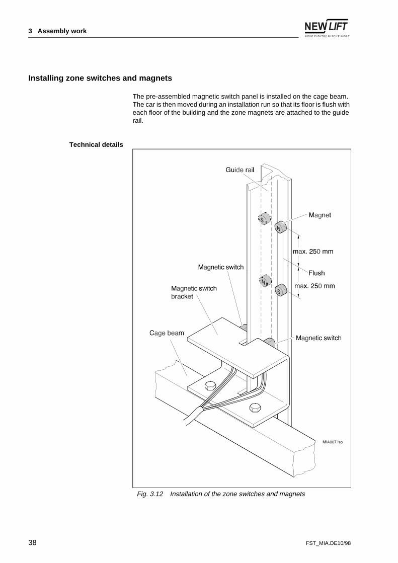
Installing zone switches and magnets
The pre-assembled magnetic switch panel is installed on the cage beam. The car is then moved during an installation run so that its floor is flush with each floor of the building and the zone magnets are attached to the guide rail.
Technical details
Fig. 3.12 Installation of the zone switches and magnets
38 FST_MIA.DE10/98

3 Assembly work
If the specified distance between magnet and magnetic switch is not observed or the play of the cage on the guide rails is too large, it may result in malfunctions in A6 Safety Monitoring Device.
Fig. 3.13 Distance between the zone switches and magnets
FST_MIA.DE10/98 39

3 Assembly work
Installing and setting the linear copying control
The following versions of the linear copying control are possible:
a) absolute value encoder on car with permanently tensioned toothed belt
b) absolute value encoder in the shaft head/pit with continuous toothed belt loop
c) cable tension sensor in the shaft head /pit.
Only option a) is described below.
Installing the absolutevalue encoder
The absolute value encoder is installed on rubber buffers on the cage beam. The rubber buffers prevent noises caused by the rotation of the toothed wheel and the tension roller being transmitted to the car. It must be ensured after the absolute value encoder is installed and that the toothed wheel and the tension roller are plumb.
Installing the toothed belt The car is moved to the top limit and the vertical distance of the ceiling plate above the toothed wheel of the absolute value encoder is determined. After the ceiling plate is installed, the toothed belt is fastened to the ceiling plate (see Page 42) and fed between the absolute value encoder toothed wheel and the tension rollers.
Make sure when moving the cage to the bottom limit that the toothed belt does not become twisted.
The loose end of the toothed belt is fixed to the floor plate (see Page 42). In order to determine the vertical distance of the floor plate, it is allowed to hang from the toothed belt just above the floor. The floor plate is then installed.
40 FST_MIA.DE10/98

3 Assembly work
Fine adjustment of thetoothed belt
The toothed belt must be centered and plumb as it runs over the absolute value encoder toothed wheel.
Wing nuts on the ceiling or floor plate are released to align the toothed belt. The central, moveable plates are displaced so that the toothed belt is centered and plumb as it runs over the toothed wheel. On completion of fine adjustment, the winged nuts are tightened.
Connecting the linear copying control
The absolute value encoder is connected to the trailing ribbon cable LIK:Xx (see Page 34).
Technical details
Fig. 3.14 Installing the absolute value encoder on the car
FST_MIA.DE10/98 41

3 Assembly work
Fig. 3.15 Installing the ceiling plate
Fig. 3.16 Installing the floor plate
42 FST_MIA.DE10/98

4 Commissioning the FST Control
4 Commissioning the FST Control
The FST Control is commissioned on completion of all the installation work. This chapter contains information relevant to the operation and commissioning of the FST Control.
4.1 Commissioning sequence
The prerequisite for commissioning the FST Control is that all NEW LIFT components are installed, connected and adjusted (see Fig. 3.1, Page 14). The FST Control is to be commissioned exactly in accordance with the steps in Fig. 4.1. The individual steps are explained from Chapter 4.3, Page 49 onward.
Fig. 4.1 Commissioning the FST Control
Commissioning linear copying control: Set direction of rotation of the absolute value encoder
Set flush position Learn drive
FST has been commissioned
Calibration drive: Check stopping precision
Check flush positions Check operability of ADM and EAZ
Commissioning of FST
Commission A6 Safety monitoring
device
Set control options: Door times
Crawl speed Password
Group mode
MIA011.abc
FST_MIA.DE10/98 43

4 Commissioning the FST Control
4.2 User interface of the FST Control
The user interface of the FST Control is depicted below. The display and operation of the FST Control is explained to the extent required for commissioning. You can obtain detailed information on operation in the “FST manual”.
Fig. 4.2 User interface of the FST Control
&/26('
,QVWDOODWLRQ�PRGH
!$;��������������������
��������������������������������������������
44 FST_MIA.DE10/98

4 Commissioning the FST Control
The display
The FST display consists of four lines each with 20 columns.
Line A displays the highest active condition of the safety monitoring device.
Line B shows the active condition and errors.
Line C displays the current status of the lift system. Two status messages can be displayed simultaneously side-by-side. When delivered, the FST Control is set to display the door status on the left and the flushness status on the right (see status messages, Page 46).
Line D shows data on the current drive mode of the FST Control.
Drive mode messages in line D
Column Display Description
1 7 Shows autotest mode.
2 ↑ Direction of movement upwards
↓ Direction of movement downwards
3-4 �� Next floor
5-8 >��@ Car and landing calls for target floor
>�� Car call for target floor
��@ Landing call for target floor
;�� Car calls blocked
��; Landing calls blocked
9 not assigned
10 * FST is linked to a group control.
11 5 Flashes during data recording onto PC card.
12 not assigned
13-20 �������� Actual time
FST_MIA.DE10/98 45

4 Commissioning the FST Control
Status messagesin line C
Status Display Description
Door �$! Door A is open.
!$� Door A is closed.
��$�! Door A is opening.
�!$�� Door A is closing.
�$ ! Photocell or reversing contact for door A is active.
�$;! Door A is locked.
��$�� Door A is blocked.
"$" Fault has occurred at door A.
��$!! Door OPEN button is active.
�!$�! Door CLOSE button is active.
Flushness = Zone message is active.
� Car is flush.
Deviation of car position from flushness (each pixel = 2.5 cm)
Position of car 3 ���� Current position of car relative to lowest floor level in mm.
3d ���� Current position of car relative to the next floor level in mm.
Car speed Y ���� Actual speed of the car in mm/s.
Operating hours %6 ���� Cumulative operating hours of drive.
Journey counter )= ������ Number of journeys completed.
Occupied memory 5HF����� Occupied memory on the PC card during ongoing recording.
46 FST_MIA.DE10/98

4 Commissioning the FST Control
The keyboard
Key functions of themain screen
Key functions in the main andtest menu
Keys Function
p Set a car call for the top floor.
q Opens the test menu.
o Set a car call for the bottom floor.
r Switches the lobby control on and off (switch function).
( Opens the main menu.
6+p Set a car call for the next floor above.
6+q Selects the next status message to the right in line C.
6+o Set a car call for the next floor below.
6+r Selects the next status message to the left in line C.
6+( Shows the FST information page.
6+r+q Switches the diagnostic function in line C on and off.
Keys Function
p Cursor moves up.
q Jumps to indicated sub-menu.
o Cursor moves down
r Jumps one menu level up.
( Opens a selected menu item.
FST_MIA.DE10/98 47

4 Commissioning the FST Control
Key functions in themenu items
The LEDs
Keys Function
p Increases a numerical value.
q Moves the cursor in the line to the right.
o Reduces a numerical value.
r Moves the cursor in the line to the left.
( Confirms the change and quits the menu item.
LED Colour
Condition
Description
RUN green on The FST Control is switched on and is functioning perfectly.
off The FST Control has no power supply.
STATUS green on The drive processor is functioning perfectly.
flashing The lobby control is switched off.
off There is a fault in the drive processor.
ERROR red on A run is not possible.
flashing One or more errors have been logged in the error list.
off No error or event has been logged.
48 FST_MIA.DE10/98

4 Commissioning the FST Control
4.3 Commissioning the linear copying control
Conditions - The installation and functional testing of all safety-engineering relevant components, both mechanical and electrical has been completed.
- The linear copying control has been fine tuned.
- The drive is completely parameterised.
If one of these set values is changed after commissioning of the linear copying control, the measured values must be checked and if necessary adapted. In all events, a new calibration drive will be necessary.
Checking the direction of rotation of the absolute value encoder.
In order to check the direction of rotation of the absolute value encoder, the car must be moved up and down a few centimetres.
Resettinglift system
➤ Turn off the entire system at the main switch.
➤ Wait for approx. 10 seconds so that all capacitors are discharged.
✔ The lift system is reset.
➤ Switch on the system.
DANGER!
Unforeseen car movements.
Severe, possibly even fatal injuries.
➤ Cordon off access to shaft.
➤ Ensure before the start of work that no-one is still in the lift shaft.
➤ Prevent unauthorised operation of the control.
FST_MIA.DE10/98 49

4 Commissioning the FST Control
Checking direction of rotation ➤ Press 6+r until “3�= ��” appears in line C.
The numerical value gives the current absolute value encoder position in mm.
➤ Move the cage up and down with the auxiliary control.
➤ Note the change in the encoder value.
✔ As the cage ascends, the encoder value increases, and as it descends, the value decreases. If the encoder value is negative, the direction of rotation of the absolute value encoder must be reversed.
Reversing the direction ofrotation
➤ Select 0$,1�0(18���326,7,21,1*���*/2%$/���',5(&7,21.
➤ Confirm selection with (.
➤ p o changes the direction of rotation.
➤ Confirm selection with (.
✔ Direction of rotation of the absolute value encoder is reversed.
➤ Check the direction of rotation again.
Checking flush position with A6 Safety Monitoring Device
The preset floor spacings must be checked and adapted to conditions on site.
The 3RVLWLRQ5(/ value of )/225�>�@ is the reference point for all floor values.
Zeroing the bottom floor ➤ Move the cage with the auxiliary control so that it is flush with Floor 0.
➤ Select 0$,1�0(18���&RQILJ���,QVWDOODWLRQ.
➤ Select 6HW�)/225��Q��with (.
➤ Set )/225���with p o.
➤ Confirm setting with (.
➤ Set <(6�with rq.
➤ Confirm selection with (.
50 FST_MIA.DE10/98

4 Commissioning the FST Control
Checking relative flushposition
➤ Select 0$,1�0(18���3RVLWLRQLQJ���)ORRU.
✔ In )/225�>�@, the 3RVLWLRQ5(/�value is ������.
➤ Select all floors with 6+p and check the 3RVLWLRQ5(/ value.
The 3RVLWLRQ5(/ corresponds to the theoretical distance of the floors from the flush position of Floor 0.
If necessary the 3RVLWLRQ5(/ values should be adapted to conditions on-site according to the system drawing.
Checking flush position with A6 Safety Monitoring Device
If the FST Control is equipped with an A6 Safety Monitoring Device, the flush positions can be automatically determined and logged by a so-called “learn drive”.
The FST Control assumes that the flush positions are at the half-way point between zone magnets A and B for a floor, in relation to Floor 0. This value is automatically entered in 0$,1�0(18���3RVLWLRQLQJ���)ORRU���3RVLWLRQ$%6.
Some of the terminals on the VSM preselection module in the control cabinet must be jumpered before a learn drive can be undertaken.
Carrying out jumpering onthe VSM preselection module
Terminals X5:5 and X5:6 are disconnected and jumpered. Terminal X8:6 is disconnected and remains free (see Fig. 4.3).
The jumpers must be long and clearly visible!
Check whether pins 2 and 3 on the VSM preselection module are plugged in.
DANGER!
Electric shocks from electrically live lines and parts.
Severe, possibly even fatal injuries.
➤ Check and ensure voltage-free condition.
➤ Carry out installation work on electrical components when they are switched off and voltage-free.
FST_MIA.DE10/98 51

4 Commissioning the FST Control
Carrying out the learn drive ➤ Select 0$,1�0(18���&RQILJ���,QVWDOODWLRQ.
➤ Select /HDUQ�GULYH�with (.
➤ Set <(6�with rq.
➤ Confirm selection with (.
✔ A learn drive is carried out and the values for the flush position is entered in 0$,1�0(18���3RVLWLRQLQJ���)ORRU���3RVLWLRQ$%6�.
Removing jumpers fromVSM preselection module
On successful completion of the learn drive, the jumpers on the VSM preselection module should be removed and the original wiring re-established.
Fig. 4.3 Jumpers and plug-in jumpers on the VSM preselection module
52 FST_MIA.DE10/98

4 Commissioning the FST Control
4.4 Carrying out a calibration drive
During a calibration drive, the retardation distances at all possible drive speeds are determined. The switch-off points for all speeds are computed with these values.
Conditions - manually checked flush positions or learn drive has been carried out
- linear copying control is operational
- The ,167$//$7,21�02'(�is switched off, if not line B displays the FST display ,167$//$7,21�02'(.
Switching offinstallation mode
➤ Select 0$,1�0(18���,QVWDOODWLRQ���,QVWDOODWLRQ�PRGH.
➤ Select 2)).
➤ Confirm selection with (.
✔ ,167$//$7,21�02'( is switched off.
Approaching the bottom floor ➤ Position the car with the auxiliary control so that its floor is flush with that of the bottom most floor.
DANGER!
Unforeseen car movements.
Severe, possibly even fatal injuries.
➤ Cordon off access to shaft.
➤ Ensure before the start of work that no-one is still in the lift shaft.
➤ Prevent unauthorised operation of the control.
FST_MIA.DE10/98 53

4 Commissioning the FST Control
Carrying out a calibrationdrive
➤ Select 0$,1�0(18���&21),*���,167$//$7,21���&$/,%5$7,21�'5,9(.
➤ Set <(6�with rq.
➤ Confirm selection with (.
✔ Four measuring runs are automatically executed for each drive speed.
- &$/,%5$7,21�67$57 flashes several times in line B of the FST display.
- During the measuring runs, &$/,%5$7,21��� is displayed several times. The figure specifies the number of measuring runs still to be executed.
- If the measuring runs have been successfully completed, the message &$/,%5$7,21�2.� flashes several times in line B.
Checking stopping precision ➤ Set “3d = �” in line C.
➤ Select 7(67�0(18���7HVW�'ULYH�21�.
➤ Approach each floor once from below and once from above.
✔ If the deviation of the Pd value per floor is smaller than or equal to ±2 mm, then the calibration drive has been successfully concluded.
With larger deviations:
- check the stopping precision of the motor
- check the load dependency of the motor
- adjust the motor regulator
- execute another calibration drive.
54 FST_MIA.DE10/98

4 Commissioning the FST Control
Checking flush positions
Each floor is approached by the cage and the stopping precision is measured and logged.
Correcting flushposition
➤ Select 0$,1�0(18���326,7,21,1*��)/225.
➤ Select 3RVLWLRQ$%6 with (.
➤ Correct 3RVLWLRQ$%6 value with po in order to correct the measured deviation from the flush position.
➤ Confirm selection with (.
➤ Select all floors with 6+po.
➤ Correct the 3RVLWLRQ$%6 value as described.
After the absolute flush positions have been corrected, the stopping precision must be checked once more at all floors.
Fig. 4.4 Measuring deviation from flush position
FST_MIA.DE10/98 55

4 Commissioning the FST Control
Checking the properfunctioning
of all ADM landing callmodules
Approach all floors and operate the lobby buttons at each floor. The lamp of the lobby button acknowledges a landing call by lighting up. The cage visits all the floors in the sequence set by the landing calls.
Checking the properfunctioning of all EAZ
floor level displays
Select all floors with the car button panel and observe how the EAZ floor display changes. The floor display must show the inputs made at the car button panel.
56 FST_MIA.DE10/98

4 Commissioning the FST Control
4.5 Commissioning the A6 Safety Monitoring Device
The A6 Safety Monitoring Device makes it possible for the car to approach to the stopping position with its doors already open. With the A6 Safety Monitoring Device, the car is also held the flush position when the doors are open (adjustment).
Approach withopen doors
➤ Select 0$,1�0(18���'2256���'2256�%$6,&.
➤ Select 35(�23(1,1*�with (.
➤ Set <(6�with rq.
➤ Confirm selection with (.
Adjustment withopen doors
➤ Select 0$,1�0(18���'5,9(.
➤ Select 5(�/(9(//,1*�with (.
➤ Set <(6�with rq.
➤ Confirm selection with (.
Checking flush positionsand approach performance
Approach all floors and check whether
- the doors open during approach.
- the car is flush.
FST_MIA.DE10/98 57

4 Commissioning the FST Control
4.6 Setting control options
Crawl drive
Setting crawl drive ➤ Select 0$,1�0(18���326,7,21,1*���*/2%$/.
➤ Select &5$:/�',67$1&( with (.
➤ Set &5$:/�',67$1&( with op.
➤ Confirm selection with (.
Password
The password protection of the FST Control prevents unauthorised modification of the set control parameters and hence any possible endangerment of persons using the lift or impairment of its operation. Three security levels for the activities of commissioning, customer service and maintenance are available.
Security levels
The password for the FST Control is four digit. The first three digits can be freely chosen while the fourth digit specifies the security level. On delivery the password is set as “����”.
Level No. Access Activity
high 1 unlimited Commissioning
medium 2 limited Customer service
low 3 non-editable menus Maintenance
58 FST_MIA.DE10/98

4 Commissioning the FST Control
Setting the password ➤ Select 0$,1�0(18���6<67(0���3$66:25'�6(77,1*.
➤ Select /(9(/���with (.
➤ Set password for /(9(/���with op.
➤ Confirm password with (.
✔ The password you selected has been set.
Proceed in the same way for Levels 2 and 3.
Blocking the main menu ➤ Select 0$,1�0(18���/2&.�0(18.
➤ Activate password settings with (.
✔ The next time that you change over from the main screen to the main menu, you will be prompted to enter your password.
Door times
Setting the opening time Opening and closing time for doors without limit switches.
➤ Select 0$,1�0(18���'2256���'2256�6(/(&7,9(.
➤ Select 23(1,1*�7,0(� with (.
➤ Set 23(1,1*�7,0( with op.
➤ Confirm selection with (.
Setting the open hold time Time for which doors remain open without waiting car or landing call.
➤ Select 0$,1�0(18���'2256���'2256�6(/(&7,9(.
➤ Select 23(1�+2/'�7,0H�with (.
➤ Set 23(1�+2/'�7,0H�with op.
➤ Confirm selection with (.
Setting reversing time After a photo-cell signal, the door is kept open for the 5(9(56(�7,0(.
➤ Select 0$,1�0(18���'2256���'2256�6(/(&7,9(.
➤ Select 5(9(56(�7,0(�with (.
➤ Set 5(9(56(�7,0( with op.
➤ Confirm selection with (.
FST_MIA.DE10/98 59

4 Commissioning the FST Control
Setting change delay Interval between a change in direction of movement of the doors.
➤ Select 0$,1�0(18���'2256���'2256�6(/(&7,9(.
➤ Select &+$1*(�'(/$<�with (.
➤ Set &+$1*(�'(/$<�with op.
➤ Confirm selection with (.
Setting minimum wait at landing
Minimum stopping time at a floor when other landing calls are waiting.
➤ Select 0$,1�0(18���'2256���'2256�6(/(&7,9(.
➤ 6HOHFW�0LQ��:DLW�/DQGLQJ�with (.
➤ 6HW�0LQ��:DLW�/DQGLQJ�with op.
➤ Confirm selection with (.
Setting minimum wait for car
Minimum stopping time at a floor when other car calls are waiting.
➤ Select 0$,1�0(18���'2256���'2256�6(/(&7,9(.
➤ 6HOHFW�0LQ��:DLW�&DU�with (.
➤ 6HW�0LQ��:DLW�&DU�with op.
➤ Confirm selection with (.
Group operation
The operation and programming of the GST Group Control is described in the “GST Manual”.
60 FST_MIA.DE10/98

5 Event and fault messages
5 Event and fault messages
5.1 LED messages on the user interface
LED Colour Condition Cause Remedy
RUN green on The power supply for the FST Control is switched on.
The hardware of the FST Control is running properly.
off The FST Control has no power supply.
Check the 24 V power supply to the FST Control.
The hardware of the FST Control is defective.
Restart the FST ControlIf the condition remains unchanged, inform the NEW LIFT hotline.
STATUS green on The drive processor is functioning perfectly.
flashing The lobby control is switched off.
r switches the lobby control on again.
off Fault in the drive processor. Restart the FST ControlIf the condition remains unchanged, inform the NEW LIFT hotline.
ERROR red on A run is not possible. Line B indicates the cause of the fault. A new run is not possible until the fault has been rectified.
flashing One or more errors have been logged in the error list.
When the error list is called up, the LED ERROR goes out.
off No error or event has been logged.
FST_MIA.DE10/98 61
5 Event and fault messages
5.2 Error list
The FST Control saves up to 100 event and error messages. If required to optimise the configuration of the control, these messages can be retrieved at any time.
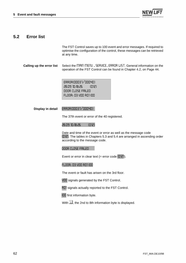
Calling up the error list Select the�0$,1�0(18���6(59,&(��(5525�/,67. General information on the operation of the FST Control can be found in Chapter 4.2, on Page 44.
Display in detail (5525�������������
The 37th event or error of the 40 registered.
���������������������������
Date and time of the event or error as well as the message code �����. The tables in Chapters 5.3 and 5.4 are arranged in ascending order according to the message code.
'RRU�&ORVH�)DLOHG
Event or error in clear text (= error code �����).
)/225�����9���5���,��
The event or fault has arisen on the 3rd floor.
9�� signals generated by the FST Control.
5�� signals actually reported to the FST Control.
,�� first information byte.
With o, the 2nd to 8th information byte is displayed.
(5525�������������
���������������������������
'RRU�&ORVH�)DLOHG
)/225�����9���5���,��
62 FST_MIA.DE10/98

5 Event and fault messages
����������������������
Second to eighth information byte.
The current conditions of the elevator system are coded in the information bytes (hexadecimal).
The individual error messages can be selected with 6+o.
(5525�������������
���������������������������
'RRU�&ORVH�)DLOHG
����������������������
FST_MIA.DE10/98 63

5 Event and fault messages
5.3 Event messages
Message Description Cause
��� &2/'67$57 The power supply to the FST has been interrupted and re-established.
- The FST Control has been turned off and on again at the fuse or at the main switch.
- There has been a power cut.
��� ,163(&7,21 Inspection work is being carried out.
The inspection switch on the cage roof is turned to INSPECTION.
��� 5(027(�5(6(7 The FST Control has been reset by the GST Group Control.
The FST Control has been reset via the serial interface.
��� &$/,%5$7,21�67$57
&$/,%5$7,21���
&$/,%5$7,21�2.�
Conditions and progress of the calibration procedure are displayed.
A calibration drive has been triggered.
��� /HDUQ�GULYH�67$57
/HDUQ�GULYH���
/HDUQ�GULYH�2.�
Conditions and progress of the learn drive are displayed.
A learn drive has been triggered.
$8;,/,$5<�02'( The auxiliary control is active. The return switch in the switch cabinet door is turned to AUXILIARY MODE.
64 FST_MIA.DE10/98

5 Event and fault messages
5.4 Error messages
Message Description Cause
� 10, Serious error in the CPU established by the ...monitoring.
Internal error
� (0(5*(1&<�6723 The “ON” and “OFF” conditions of the triggered emergency stop device are displayed.
Break in the safety monitoring device in the emergency stop circuit.
� 'ULYH�%RRW Error during start up of drive process.
Internal error
� 'ULYH�:DWFKGRJ Serious CPU error in the drive process area determined by the monitoring.
Internal error
� 'ULYHU�2[HU Error during transmission of the data relevant to the drive process.
Internal error
� 23(1�'225�/2&. Door contact open during the run.
INFO-BYTE 1:Status of the safety monitoring device.
Break in safety monitoring device in door circuit during run.
�� '225�&/26(�)$,/(' Door cannot be closed.
INFO-BYTE 1:0 = Door A1 = Door B2 = Door C
INFO-BYTE 2:1 = does not close because the opening switch is still active.2 = does not close completely, the closed switch has not yet been reached.
- The cage door is mechanically or electrically blocked.
- The door limit switched not activated.
Continued overleaf
FST_MIA.DE10/98 65
5 Event and fault messages
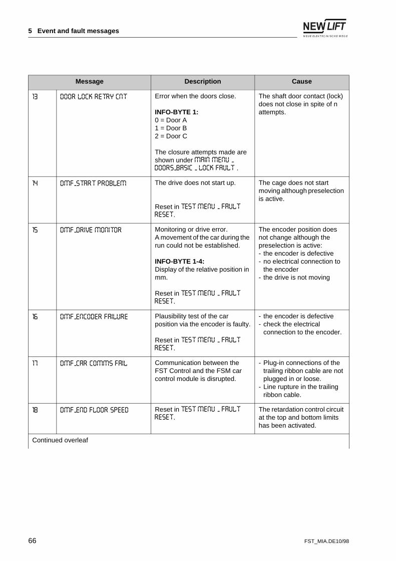
�� '225�/2&.�5(75<�&17 Error when the doors close.
INFO-BYTE 1:0 = Door A1 = Door B2 = Door C
The closure attempts made are shown under 0$,1�0(18���'2256�%$6,&���/2&.�)$8/7�.
The shaft door contact (lock) does not close in spite of n attempts.
�� '0)�67$57�352%/(0 The drive does not start up.
Reset in 7(67�0(18���)$8/7�5(6(7.
The cage does not start moving although preselection is active.
�� '0)�'5,9(�021,725 Monitoring or drive error.A movement of the car during the run could not be established.
INFO-BYTE 1-4:Display of the relative position in mm.
Reset in 7(67�0(18���)$8/7�5(6(7.
The encoder position does not change although the preselection is active:- the encoder is defective- no electrical connection to
the encoder- the drive is not moving
�� '0)�(1&2'(5�)$,/85( Plausibility test of the car position via the encoder is faulty.
Reset in 7(67�0(18���)$8/7�5(6(7.
- the encoder is defective- check the electrical
connection to the encoder.
�� '0)�&$5�&2006�)$,/ Communication between the FST Control and the FSM car control module is disrupted.
- Plug-in connections of the trailing ribbon cable are not plugged in or loose.
- Line rupture in the trailing ribbon cable.
�� '0)�(1'�)/225�63((' Reset in 7(67�0(18���)$8/7�5(6(7.
The retardation control circuit at the top and bottom limits has been activated.
Continued overleaf
Message Description Cause
66 FST_MIA.DE10/98

5 Event and fault messages
�� '0)�0,66,1*�=21( No zone.
INFO-BYTE 1-4:Display of the relative position in mm.
Reset in 7(67�0(18���)$8/7�5(6(7.
The car has reached the flush position, but has not received a zone message from A6 Safety Monitoring Device.
Check A6 Safety Monitoring Device and the zone magnetic switches.
�� '0)�%5$.(�)$,/85( The brakes do not respond or cannot be triggered.
Reset in 7(67�0(18���)$8/7�5(6(7.
- The brake does not open although preselection is active.
- The brake does not close despite stop.
Monitoring via input VSM:X4.7
�� '0)�02725�)$,/85( Motor error Overheated motorMonitoring via input VSM:X4.5
�� &217$&725�021,725 Fault in motor contacts.
Reset in 7(67�0(18���)$8/7�5(6(7.
The main contacts do not release after the flush position is reached.Monitoring via input VSM:X4.6
�� 6/,3�2876,'(�/(9(/ Unforeseen car movement out of stopping position.
INFO-BYTE 1-4:Display of the relative position in mm.
The drive does not stop in the flush position despite removal of the preselection.The retardation distance of the drive is too long.
�� 6/,3�2876,'(�=21( Unforeseen car movement out of the zone.
INFO-BYTE 1-4:Display of the relative position in mm.
The drive does not stop in the flush position despite removal of the preselection.The retardation distance of the drive is too long.
�� %86�,�)�7,0(287 Error at LON bus interface. Internal error
�� 67$57�$%257 Start up of motor is interrupted. Internal error
�� 6723�$%257 Motor stop interrupted. Internal error
Continued overleaf
Message Description Cause
FST_MIA.DE10/98 67

5 Event and fault messages
�� 5(/(9(//,1*�$%257 An error has occurred during correction and interrupted it.
The zone circuit A6 has a fault.
�� %<3$66�)$,/85( The safety bypass during approach with open doors is missing.
The zone circuit A6 has a fault.
�� '225�/2&.�7,0(287 The delay between activation of the cage door contact and lock contact is in 0DLQ�0HQX���'RRUV�%DVLF���'RRU�/RFN�7LPHRXW.
The cage door is closed, however the lock contact does not close in the specified time.
Message Description Cause
68 FST_MIA.DE10/98

6 Terminal and pin assignment
6 Terminal and pin assignment
Only the terminal and pin assignments relevant to installation and commissioning of the FST Control are specified below. A complete overview of the terminal and pins of the FST Control and its components is contained in the FST manual.
Trailing ribbon cable
For a description of the pins of the trailing ribbon cable see Fig. 3.10 on Page 34.
FST: X2 Colour code Description
1 rs Data signal “A”
2 ge Clock signal “A”
3 rt Encoder signal “A”
4 br +24 V DC
5 ws GND
6 gr Data signal “B”
7 gn Clock signal “B”
8 bl Encoder signal “B”
9 Shielding PE
FST_MIA.DE10/98 69

6 Terminal and pin assignment
FST: X4 Colour code Description
1 rs Bus signal “A”
2 ge Telephone “A”
3 rt Voice “A”
4 bn Emergency power supply (HSG)
5 ws + 8 - 24 V DC (power supply for backup power unit)
6 gr Bus signal “B”
7 gn Telephone “B”
8 bl Voice “B”
9 Shielding PE
VSM: X8 Description
1 +24 V DC
2 +24 V DC
3 GND
4 GND
5 Zone switch A
6 Zone switch B
7 Correction switch, top
8 Correction switch, bottom
70 FST_MIA.DE10/98

6 Terminal and pin assignment
The labelling and assignment of terminals X100/1, X100/2, X200/1 and X200/2 can be obtained from the system-specific circuit diagrams.
FSM: X1 Colour code Description
1 rs Bus signal “A”
2 ge Telephone “A”
3 rt Voice “A”
4 bn Emergency power supply (HSG)
5 ws + 8 - 24 V DC (power supply for HSG)
6 gr Bus signal “B”
7 gn Telephone “B”
8 bl Voice “B”
9 NC / Shielding
not connected / shielding of FST
FSM: X13 Description
1 +24 V DC
2 +24 V DC
3 GND
4 GND
5 Zone switch A
6 Zone switch B
7 Correction switch, top
8 Correction switch, bottom
FST_MIA.DE10/98 71

6 Terminal and pin assignment
LON bus
VSM preselection module
FSM car control module
PIN Colour code Description
1 sw Bus signal “A”
2 ws Bus signal “B”
3 rt + 24 V / 4 A
4 vi GND
X5 Colour code Description
1 rt +24 V DC
2 vi GND
3 rt Zone enabling
4 rt Zone signal
5 vi Zone switch A
6 vi Zone switch B
X12 Description
1 +24V DC
2 Inspection ON
3 Inspection UP
4 Inspection DOWN
5 Inspection FAST
72 FST_MIA.DE10/98

7 Index
7 Index
AA6 Safety Monitoring Device ........................................50, 57Absolute value encoder .....................................................40Accident prevention .......................................................5, 10Adjustment with open doors ...............................................57ADM landing call module .............................................37, 56Approach with open doors .................................................57Auxiliary control ..........................................................35, 53
BBus Plan ..........................................................................27
CCable tension sensor .........................................................40Cage functions .................................................................29Calibration drive ................................................................53Car button panel ...............................................................56Car call panel ...................................................................25Car calls ...........................................................................60Ceiling plate .....................................................................40Commissioning sequence ..................................................43Control cabinet .................................................................18Crawl drive .......................................................................58
DDirection of rotation of the absolute value encoder ...............49Display .............................................................................45Disposal ...........................................................................12Door times .......................................................................59
EEAZ position indicator ...........................................25, 27, 37Electronics module ................................................12, 27, 37Emergency STOP switch ...................................................29Environmental protection ...............................................5, 12Error ................................................................................62Event ...............................................................................62Explosion protection regulations ...........................................9
FFire protection regulations ...................................................9First aid ..............................................................................9Fixings .............................................................................23Floor plate ........................................................................40Flush position .......................................................50, 55, 57FPM car operating panel module ............................25, 27, 29FSM car control module ...................................25, 27, 31, 72FST circuit board ..............................................................44
FST_MIA.DE10/98 73

7 Index
GGeneral safety provisions .................................................... 9GST Group Control .............................................. 30, 32, 60
HHandling electronics modules ............................................ 12Hanging cable (see trailing ribbon cable) ................ 16, 33, 69
IInspection control ............................................................. 35Installation mode .................................................. 20, 35, 53
KKey functions ................................................................... 47Keyboard ......................................................................... 47
LLanding calls ................................................................... 60Learn drive ...................................................................... 51LEDs ......................................................................... 48, 61Linear copying control ................................................. 40, 49LON bus .................................................................... 37, 72
MMagnetic switch panel ...................................................... 38
OOutput load ...................................................................... 21
PPackaging ....................................................................... 12Password ........................................................................ 58Personal safety equipment ................................................ 12Pin assignment ................................................................ 69Plug-in jumper ..................................................... 27, 30, 51
QQualifications of the installing engineer ................................. 9Qualified electrician ............................................................ 9
RRecycling ........................................................................ 12Re-levelling (see adjustment with open doors) .................... 57Remote control unit .................................................... 27, 35Residual dangers ............................................................. 10
SSafety catch ..................................................................... 35Safety monitoring device ................................. 28, 35, 45, 49Safety provisions ................................................................ 9
74 FST_MIA.DE10/98

7 Index
Scope of delivery ..............................................................16Serial number ...................................................................17Status message ................................................................45Stopping precision ............................................................54Symbols .............................................................................6
TTension rollers ..................................................................40Terminal assignment .........................................................69Terminal resistance (terminator) ...................................27, 37Toothed belt .....................................................................40Trailing cable (see trailing ribbon cable) ..................16, 33, 69Trailing ribbon cable ..............................................16, 33, 69
UUser interface ...................................................................44
VVSM preselection module ............................................51, 72
WWarning signs .....................................................................6Weight of the control cabinet ..............................................21
ZZone circuit (see A6 Safety Monitoring Device) ..............50, 57Zone magnets ..................................................................38Zone switches ..................................................................38
FST_MIA.DE10/98 75

Your NEW LIFT Hotline: e-mail: [email protected]
Adi-Maislinger-Straße 12 Tel.: + 49 (0) 89 / 74 35 44 - 0D-81373 München Fax: + 49 (0) 89 / 7 69 34 85