Fibre-reinforced plastic composites Determination of...
26
BRITISH STANDARD BS EN ISO 14125:1998 Incorporating Technical Corrigendum No. 1 Fibre-reinforced plastic composites — Determination of flexural properties The European Standard EN ISO 14125:1998 has the status of a British Standard ICS 83.120 Licensed Copy: Institute Of Technology Tallaght, Institute of Technology, Sat Sep 22 04:52:02 GMT+00:00 2007, Uncontrolled Copy, (c) BSI
Transcript of Fibre-reinforced plastic composites Determination of...
BRITISH STANDARD BS EN ISO 14125:1998Incorporating Technical Corrigendum No. 1
Fibre-reinforced plastic composites —Determination of flexural properties
The European Standard EN ISO 14125:1998 has the status of a British Standard
ICS 83.120
���������������� ������������������������������� �������������
Lice
nsed
Cop
y: In
stitu
te O
f Tec
hnol
ogy
Tal
lagh
t, In
stitu
te o
f Tec
hnol
ogy,
Sat
Sep
22
04:5
2:02
GM
T+
00:0
0 20
07, U
ncon
trol
led
Cop
y, (
c) B
SI
BS EN ISO 14125:1998
This British Standard, having been prepared under the direction of the Sector Board for Materials and Chemicals, was published under the authority of the Standards Board and comes into effect on 15 June 1998
© BSI 24 February 2003
ISBN 0 580 30015 3
National forewordThis British Standard is the English language version of EN ISO 14125:1998, including Corrigendum July 2002. It is identical with ISO 14125:1998, including Corrigendum July 2001.
The UK participation in its preparation was entrusted to Technical Committee PRI/42, Fibre reinforced thermosetting plastics and prepregs, which has the responsibility to:
A list of organizations represented on this committee can be obtained on request to its secretary.
Cross-references
Attention is drawn to the fact that CEN and CENELEC standards normally include an annex which lists normative references to international publications with their corresponding European publications. The British Standards which implement these international or European publications may be found in the BSI Standards Catalogue under the section entitled “International Standards Correspondence Index”, or by using the “Find” facility of the BSI Standards Electronic Catalogue.
This publication does not purport to inclide all the necessary provisions of a contract. Users of British Standards are responsible for its correct application.
Compliance with a British Standard does not of itself confer immunity from legal obligations.
— aid enquirers to understand the text;— present to the responsible international/European committee any
enquiries on the interpretation, or proposals for change, and keep the UK interests informed;
— monitor related international and European developments and promulgate them in the UK.
Summary of pages
This document comprises a front cover, an inside front cover, pages i and ii, the EN ISO title page, the EN ISO foreword page, the ISO title page, pages ii to iv, pages 1 to 16, an inside back cover and a back cover.
The BSI copyright notice displayed in this document indicates when the document was last issued.
Amendments issued since publication
Amd. No. Date Comments
14168Corrigendum No. 1
24 February 2003 Revision of 1.3
Lice
nsed
Cop
y: In
stitu
te O
f Tec
hnol
ogy
Tal
lagh
t, In
stitu
te o
f Tec
hnol
ogy,
Sat
Sep
22
04:5
2:02
GM
T+
00:0
0 20
07, U
ncon
trol
led
Cop
y, (
c) B
SI

EUROPEAN STANDARD
NORME EUROPÉENNE
EUROPÄISCHE NORM
EN ISO 14125
March 1998
ICS 83.120 Supersedes EN 63:1977Incorporating Corrigendum July 2002
Descriptors: See ISO document
English version
Fibre-reinforced plastic composites — Determination of flexural properties
(ISO 14125:1998)
Composites plastiques renforcés de fibres —Détermination des propriétés de flexion(ISO 14125:1998)
This European Standard was approved by CEN on 15 February 1998.CEN members are bound to comply with the CEN/CENELEC InternalRegulations which stipulate the conditions for giving this European Standardthe status of a national standard without any alteration. Up-to-date lists andbibliographical references concerning such national standards may be obtainedon application to the Central Secretariat or to any CEN member.This European Standard exists in three official versions (English, French,German). A version in any other language made by translation under theresponsibility of a CEN member into its own language and notified to theCentral Secretariat has the same status as the official versions.CEN members are the national standards bodies of Austria, Belgium,Czech Republic, Denmark, Finland, France, Germany, Greece, Iceland, Ireland,Italy, Luxembourg, Netherlands, Norway, Portugal, Spain, Sweden,Switzerland and United Kingdom.
CENEuropean Committee for Standardization
Comité Européen de NormalisationEuropäisches Komitee für Normung
Central Secretariat: rue de Stassart 36, B-1050 Brussels
© 1998 CEN All rights of exploitation in any form and by any means reserved worldwide for CEN national Members.
Ref. No. EN ISO 14125:1998 E
Lice
nsed
Cop
y: In
stitu
te O
f Tec
hnol
ogy
Tal
lagh
t, In
stitu
te o
f Tec
hnol
ogy,
Sat
Sep
22
04:5
2:02
GM
T+
00:0
0 20
07, U
ncon
trol
led
Cop
y, (
c) B
SI
EN ISO 14125:1998
© BSI 24 February 2003
Foreword
The text of the International Standard ISO 14125:1998 has been prepared by Technical Committee ISO/TC 61 “Plastics” in collaboration with Technical Committee CEN/TC 249 “Plastics”, the Secretariat of which is held by IBN.
This European Standard supersedes EN 63:1977.
This European Standard shall be given the status of a national standard, either by publication of an identical text or by endorsement, at the latest by September 1998, and conflicting national standards shall be withdrawn at the latest by September 1998.
According to the CEN/CENELEC Internal Regulations, the national standards organizations of the following countries are bound to implement this European Standard: Austria, Belgium, Czech Republic, Denmark, Finland, France, Germany, Greece, Iceland, Ireland, Italy, Luxembourg, Netherlands, Norway, Portugal, Spain, Sweden, Switzerland and the United Kingdom.
Endorsement noticeThe text of the International Standard ISO 14125:1998 was approved by CEN as a European Standard without any modification.
Endorsement noticeThe text of ISO 14125:1998/Cor.1:2001 has been approved by CEN as a European Corrigendum without any modifications.
Lice
nsed
Cop
y: In
stitu
te O
f Tec
hnol
ogy
Tal
lagh
t, In
stitu
te o
f Tec
hnol
ogy,
Sat
Sep
22
04:5
2:02
GM
T+
00:0
0 20
07, U
ncon
trol
led
Cop
y, (
c) B
SI
Incorporating Technical Corrigendum No. 12001-07-15
Lice
nsed
Cop
y: In
stitu
te O
f Tec
hnol
ogy
Tal
lagh
t, In
stitu
te o
f Tec
hnol
ogy,
Sat
Sep
22
04:5
2:02
GM
T+
00:0
0 20
07, U
ncon
trol
led
Cop
y, (
c) B
SI

EN ISO 14125:1998
ii
Contents
Page
Foreword iii
Introduction iv
1 Scope 1
2 Normative references 1
3 Principle 2
4 Definitions 2
5 Apparatus 3
6 Test specimens 4
7 Number of test specimens 6
8 Conditioning 6
9 Procedure 6
10 Calculation and expression of results 7
11 Precision 9
12 Test report 10
Annex A (normative) Other test specimens 11
Annex B (normative) Large-deflection corrections — Calculation and expression of results 11
Descriptors: Plastics, reinforced plastics, tests, bend tests, determination, flexural strength, test specimens.
Lice
nsed
Cop
y: In
stitu
te O
f Tec
hnol
ogy
Tal
lagh
t, In
stitu
te o
f Tec
hnol
ogy,
Sat
Sep
22
04:5
2:02
GM
T+
00:0
0 20
07, U
ncon
trol
led
Cop
y, (
c) B
SI

EN ISO 14125:1998
© BSI 24 February 2003 iii
Foreword
ISO (the International Organization for Standardization) is a worldwide federation of national standards bodies (ISO member bodies). The work of preparing International Standards is normally carried out through ISO technical committees. Each member body interested in a subject for which a technical committee has been established has the right to be represented on that committee. International organizations, governmental and non-governmental, in liaison with ISO, also take part in the work. ISO collaborates closely with the International Electrotechnical Commission (IEC) on all matters of electrotechnical standardization.
Draft International Standards adopted by the technical committees are circulated to the member bodies for voting. Publication as an International Standard requires approval by at least 75 % of the member bodies casting a vote.
International Standard ISO 14125 was prepared by Technical Committee ISO/TC 61, Plastics, Subcommittee SC 13, Composites and reinforcement fibres.
Annex A and Annex B form an integral part of this International Standard.
Lice
nsed
Cop
y: In
stitu
te O
f Tec
hnol
ogy
Tal
lagh
t, In
stitu
te o
f Tec
hnol
ogy,
Sat
Sep
22
04:5
2:02
GM
T+
00:0
0 20
07, U
ncon
trol
led
Cop
y, (
c) B
SI
BS EN ISO 14125:1998
iv © BSI 24 February 2003
IntroductionThis standard is based on ISO 178 but deals with fibre-reinforced plastic composites. As such it retains the test conditions relevant for glass-fibre-reinforced systems. The test conditions are extended from ISO 178 to include both three-point (Method A) and four-point (Method B) loading geometries, and to include conditions for composites based on newer fibres such as carbon and aramid fibres.
Other source documents consulted include ASTM D 790 (four-point loading), prEN 2562 (test conditions), CRAG 200 and JIS K 7074 (use of shims for four-point loading, Figure 6). The overall specimen length for four-point loading is the same as for three-point loading.
The scope of ISO 178 will be revised and limited to unreinforced and filled plastics.
EN 63:1977, Glass-reinforced plastics — Determination of flexural properties — Three-point test, will be withdrawn.
Lice
nsed
Cop
y: In
stitu
te O
f Tec
hnol
ogy
Tal
lagh
t, In
stitu
te o
f Tec
hnol
ogy,
Sat
Sep
22
04:5
2:02
GM
T+
00:0
0 20
07, U
ncon
trol
led
Cop
y, (
c) B
SI
EN ISO 14125:1998
© BSI 24 February 2003 1
1 Scope
1.1 This International Standard specifies a method for determining the flexural properties of fibre-reinforced plastic composites under three-point (Method A) and four-point (Method B) loading. Standard test specimens are defined but parameters included for alternative specimen sizes for use where appropriate. A range of test speeds is included.
1.2 The method is not suitable for the determination of design parameters, but may be used for screening materials, or as a quality-control test.NOTE For example, the flexural modulus is only an appropriate value of the tensile Young’s modulus of elasticity as the test is not for the additional deflection due to the shear stress which leads to a lower value of the flexural modulus but uses test span/specimen thickness ratios that minimise this effect. Differences between tensile and flexural properties are also caused by the material structure/lay-up.
1.3 The method is suitable for fibre-reinforced thermoplastic and thermosetting plastic composites.
ISO 178, Plastics — Determination of flexural properties, applies to bulk compounds having fibres shorter than 7,5 mm. This is generally the case with materials intended for injection moulding.
1.4 The method is performed using specimens which may be moulded to the chosen dimensions, machined from the central portion of the standard multi-purpose test specimen (see ISO 3167) or machined from semi-finished or finished products such as mouldings or laminates.
1.5 The method specifies preferred dimensions for the specimen. Tests which are carried out on specimens of other dimensions, or on specimens which are prepared under different conditions, may produce results which are not comparable. Other factors, such as the speed of testing and the conditioning of the specimens can influence the results. For materials which are not homogeneous through the section, or above the linear-elastic response region, the result applies only to the thickness and structure tested. Consequently, when comparative data are required, these factors must be carefully controlled and recorded.
2 Normative referencesThe following standards contain provisions which, through reference in this text, constitute provisions of this International Standard. At the time of publication, the editions indicated were valid. All standards are subject to revision, and parties to agreements based on this International Standard are encouraged to investigate the possibility of applying the most recent editions of the standards indicated below. Members of IEC and ISO maintain registers of currently valid International Standards.
ISO 178:1993, Plastics — Determination of flexural properties.
ISO 291:1997, Plastics — Standard atmospheres for conditioning and testing.
ISO 293:1986, Plastics — Compression moulding test specimens of thermoplastic materials.
ISO 294-1:1996, Plastics — Injection moulding of test specimens of thermoplastic materials — Part 1: General principles, and moulding of multipurpose and bar test specimens.
ISO 295:1991, Plastics — Compression moulding of test specimens of thermosetting materials.
ISO 1268:1974, Plastics — Preparation of glass fibre reinforced, resin bonded, low-pressure laminated plates or panels for test purposes (under revision).
ISO 2602:1980, Statistical interpretation of test results — Estimation of the mean — Confidence interval.
ISO 2818:1994, Plastics — Preparation of test specimens by machining.
ISO 3167:1993, Plastics — Multipurpose test specimens.
ISO 5893:1993, Rubber and plastics test equipment — Tensile, flexural and compression types (constant rate of traverse) — Description.
Lice
nsed
Cop
y: In
stitu
te O
f Tec
hnol
ogy
Tal
lagh
t, In
stitu
te o
f Tec
hnol
ogy,
Sat
Sep
22
04:5
2:02
GM
T+
00:0
0 20
07, U
ncon
trol
led
Cop
y, (
c) B
SI
EN ISO 14125:1998
2 © BSI 24 February 2003
3 Principle
The test specimen, supported as a beam, is deflected at a constant rate until the specimen fractures or until the deformation reaches some pre-determined value. During this procedure, the force applied to the specimen and the deflection are measured.
The method is used to investigate the flexural behaviour of the test specimens and for determining the flexural strength, flexural modulus and other aspects of the flexural stress/strain relationship under the conditions defined. It applies to a freely supported beam, loaded in three- or four-point flexure. The test geometry is chosen to limit shear deformation and to avoid an interlaminar shear failure.NOTE The four-point loading geometry provides a constant bending moment between the central loading members. The compressive contact stresses due to the two central loading members are lower in comparison with the stresses induced under the single loading member of the three-point test. The four-point geometry is chosen so that the centre span equals one-third of the outer span. The distance between the outer support points is the same as in the equivalent three-point loading case, therefore the same specimen can be used.
4 DefinitionsFor the purpose of this International Standard, the following definitions apply.
4.1 speed of testing, vthe rate of relative movement between the supports and the loading member(s), expressed in millimetres per minute (mm/min)
4.2 flexural stress, �fthe nominal stress in the outer surface of the test specimen at mid-span. It is calculated according to the relationship given in Clause 10, equation (3) or (8), and is expressed in megapascals (MPa)
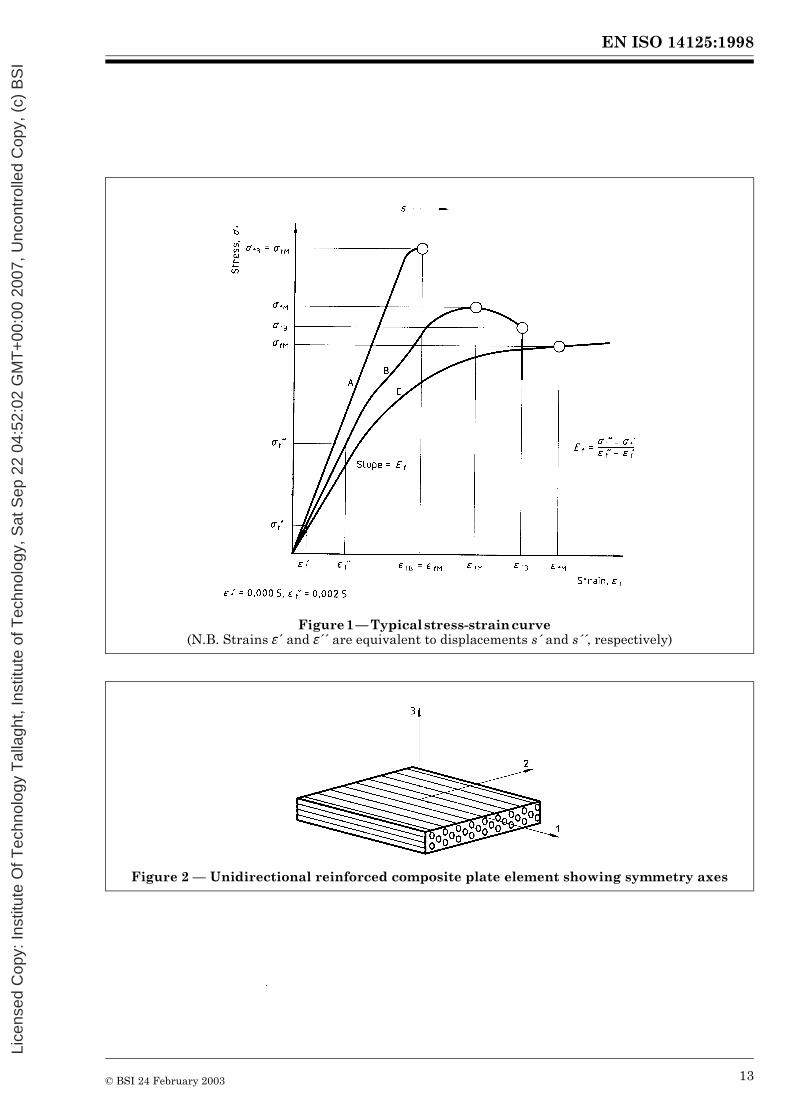
4.3 flexural stress at break (rupture), �fBthe flexural stress at break (or rupture) of the test specimen (see Figure 1, curves A and B). It is expressed in megapascals (MPa)
4.4 flexural strength, �fMthe flexural stress sustained by the test specimen at the maximum load (see Figure 1) for acceptable failure modes (see subclause 9.9 and Figure 6). It is expressed in megapascals (MPa)
4.5 deflection, sthe distance through which the top or bottom surface of the test specimen at mid-span has deflected during flexure from its original position. It is expressed in millimetres (mm)
4.6 deflection at break, sBthe deflection at break of the test specimen (see Figure 1, curves A and B). It is expressed in millimetres (mm)
4.7 deflection at flexural strength, sMthe deflection at the load equal to the flexural strength (4.4) (see Figure 1, curves A and B). It is expressed in millimetres (mm)
4.8 flexural strain, �fthe nominal fractional change in length of an element in the outer surface of the test specimen at mid-span. It is used for calculating the flexural modulus (4.9) and is expressed as a dimensionless ratio
Lice
nsed
Cop
y: In
stitu
te O
f Tec
hnol
ogy
Tal
lagh
t, In
stitu
te o
f Tec
hnol
ogy,
Sat
Sep
22
04:5
2:02
GM
T+
00:0
0 20
07, U
ncon
trol
led
Cop
y, (
c) B
SI

EN ISO 14125:1998
© BSI 24 February 2003 3
4.9 modulus of elasticity in flexure; flexural modulus; chord modulus, Erthe ratio of the stress difference (�f´´ – �f ���´) divided by the corresponding strain difference �f´´ = 0,00 25 – �f �´ = 0,000 5) (see 10.1.2 and 10.2.2). It is expressed in megaspascals (MPa)NOTE With computer-assisted equipment, the determination of the modulus using two distinct stress/strain points can be replaced by a linear regression procedure applied to the part of the curve between the two points.
4.10 interlaminar shear modulus, G13the shear modulus in the through-thickness direction for laminated materials. It is expressed in megapascals (MPa)NOTE For materials with mainly in-plane reinforcement, the shear modulus G13 is of the order of 3 000 MPa to 6 000 MPa.
4.11 specimen coordinate axes (aligned materials)the coordinate axes for an aligned material are defined in Figure 2. The direction parallel to the fibre axes is defined as the “1” direction and the direction perpendicular to it the “2” direction.
For other materials, the 1,2 and 3 directions are generally described by the x, y, z system of coordinatesNOTE 1 The “1” direction is also referred to as the 0 degree (0�) or longitudinal direction, and the “2” direction as the 90 degree (90�) or transverse direction.
NOTE 2 A similar definition can be used for material with a preferred fibre lay-up or in cases where a direction (e.g. the lengthwise direction) can be related to the production process.
For materials with anisotropy as defined above, the designations include an additional subscript “1” or “2” to indicate the direction tested
5 Apparatus
5.1 Test machine
5.1.1 General
The test machine shall comply with ISO 5893 as appropriate to the requirements given in 5.1.2, 5.1.3 and 5.1.4, as follows:
5.1.2 Speed of testing
The test machine shall be capable of maintaining the speed of testing (4.1), as specified in Table 1.
Table 1 — Recommended values for the speed of testing
The speed 0,5 mm/min is not indicated in ISO 5893. The tolerances on the speeds 1 mm/min and 2 mm/min are lower than those indicated in ISO 5893.
Speed(mm/min)
Tolerance(%)
0,5 �201 �202 �205 �20
10 �2020 �1050 �10
100 �10200 �10500 �10
Lice
nsed
Cop
y: In
stitu
te O
f Tec
hnol
ogy
Tal
lagh
t, In
stitu
te o
f Tec
hnol
ogy,
Sat
Sep
22
04:5
2:02
GM
T+
00:0
0 20
07, U
ncon
trol
led
Cop
y, (
c) B
SI
EN ISO 14125:1998
4 © BSI 24 February 2003
5.1.3 Loading member(s) and supports
Supports and central loading member(s) are arranged according to Figure 3 (3-point) or Figure 4 (4-point). The radius R1 and the radius R2 shall be as given in Table 2. The axes of the supports and the loading member(s) shall be parallel.
The span L (distance between the supports) shall be adjustable.
Table 2 — Loading and support member dimensions
5.1.4 Load and deflection indicators
The error in the indicated force shall not exceed �1 % and that in the indicated deflection shall not exceed �1 % of full scale (see ISO 5893).
Deflection obtained from movement of the test machine crosshead shall be corrected for loading train deflection and indentation at the loading points.
5.2 Micrometers and gauges
5.2.1 Micrometer, or equivalent, capable of reading to 0,01 mm or less, and suitable for measuring the width b and thickness h of the test specimen.
The micrometer shall have contact faces appropriate to the surface being measured (i.e. flat faces for flat, polished surfaces and hemispherical faces for irregular surfaces).
5.2.2 Vernier callipers, or equivalent, accurate to within 0,1 % of the span L, for determining the span (see 9.2).
6 Test specimens
6.1 Shape and dimensions
6.1.1 General
Unless otherwise agreed, the dimensions of the specimen shall comply with those given in the standard for the material under test or those given in 6.1.3.
6.1.2 Test direction
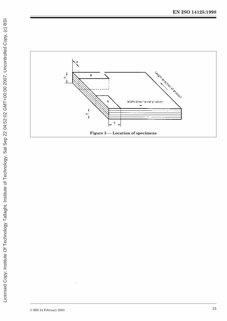
The test specimen axis shall be in one of the principal directions (see 4.11 and Figure 5).NOTE When the material under test shows a significant difference in properties between the two principal directions (i.e. “1” and “2”), it is recommended that testing be carried out in both directions.
If, because of the application, the material is subjected to stress at some specific orientation to the principal directions, the material shall be tested in that orientation. The orientation of the test specimens relative to the principal directions shall be recorded.
Dimension Value(mm)
R1 5 � 0,2R2 for h � 3 mm 2 � 0,2R2 for h > 3 mm 5 � 0,2
Lice
nsed
Cop
y: In
stitu
te O
f Tec
hnol
ogy
Tal
lagh
t, In
stitu
te o
f Tec
hnol
ogy,
Sat
Sep
22
04:5
2:02
GM
T+
00:0
0 20
07, U
ncon
trol
led
Cop
y, (
c) B
SI
EN ISO 14125:1998
© BSI 24 February 2003 5
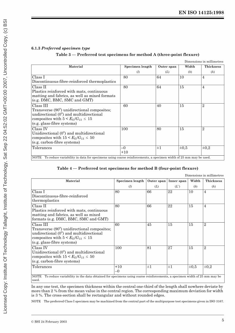
6.1.3 Preferred specimen type
Table 3 — Preferred test specimens for method A (three-point flexure)
Table 4 — Preferred test specimens for method B (four-point flexure)
In any one test, the specimen thickness within the central one-third of the length shall nowhere deviate by more than 2 % from the mean value in the central region. The corresponding maximum deviation for width is 3 %. The cross-section shall be rectangular and without rounded edges.NOTE The preferred Class I specimen may be machined from the central part of the multipurpose test specimens given in ISO 3167.
Dimensions in millimetres
Material Specimen length Outer span Width Thickness
(l) (L) (b) (h)
Class IDiscontinuous-fibre-reinforced thermoplastics
80 64 10 4
Class IIPlastics reinforced with mats, continuous matting and fabrics, as well as mixed formats (e.g. DMC, BMC, SMC and GMT)
80 64 15 4
Class IIITransverse (90�) unidirectional composites; undirectional (0�) and multidirectional composites with 5 < Ef1/G13 � 15 (e.g. glass-fibre systems)
60 40 15 2
Class IVUnidirectional (0�) and multidirectional composites with 15 < Ef1/G13 � 50 (e.g. carbon-fibre systems)
100 80 15 2
Tolerances –0+10
�1 �0,5 �0,2
NOTE To reduce variability in data for specimens using coarse reinforcements, a specimen width of 25 mm may be used.
Dimensions in millimetres
Material Specimen length Outer span Inner span Width Thickness
(l) (L) (L´) (b) (h)
Class IDiscontinuous-fibre-reinforced thermoplastics
80 66 22 10 4
Class IIPlastics reinforced with mats, continuous matting and fabrics, as well as mixed formats (e.g. DMC, BMC, SMC and GMT)
80 66 22 15 4
Class IIITransverse (90�) unidirectional composites; undirectional (0�) and multidirectional composites with 5 < Ef1/G13 � 15 (e.g. glass-fibre systems)
60 45 15 15 2
Class IVUnidirectional (0�) and multidirectional composites with 15 < Ef1/G13 � 50 (e.g. carbon-fibre systems)
100 81 27 15 2
Tolerances +10–0
�1 �1 �0,5 �0,2
NOTE To reduce variability in the data obtained for specimens using coarse reinforcements, a specimen width of 25 mm may be used.
Lice
nsed
Cop
y: In
stitu
te O
f Tec
hnol
ogy
Tal
lagh
t, In
stitu
te o
f Tec
hnol
ogy,
Sat
Sep
22
04:5
2:02
GM
T+
00:0
0 20
07, U
ncon
trol
led
Cop
y, (
c) B
SI
EN ISO 14125:1998
6 © BSI 24 February 2003
In any one test, the specimen thickness over the complete length shall nowhere deviate by more than 2 % from the mean value. The corresponding maximum deviation for width is 3 %. The cross-section shall be rectangular and without rounded edges.
6.1.4 Other test specimens
When it is not possible or desirable to use the preferred test specimen, the dimensions of L, l, h and b in Table A.1 and Table A.2 in Annex A shall apply.
6.2 Specimen preparation
6.2.1 Moulding and extrusion compounds
Specimens shall be prepared in accordance with the relevant material specification. When none exists, or when otherwise specified, specimens shall be either directly compression moulded or directly injection moulded from the material in accordance with ISO 293, ISO 294-1 or ISO 295, as appropriate.
6.2.2 Plates
Specimens shall be machined from plates in accordance with ISO 2818.
6.2.3 Long-fibre-reinforced plastic materials
Specimens shall be machined from a panel prepared in accordance with ISO 1268 or another specified or agreed-upon procedure. Guidance on machining of plastics is given in ISO 2818.
6.3 Checking the test specimens
The specimens shall be free of twist and shall have mutually perpendicular pairs of parallel surfaces. The surfaces and edges shall be free from scratches, pits, sink marks and flashes. The specimens shall be checked for conformity with these requirements by visual observation against straight-edges, squares and flat plates, and by measuring with micrometer callipers. Specimens showing measurable or observable departure from one or more of these requirements shall be rejected or machined to the required size and shape before testing.
7 Number of test specimens
7.1 At least five test specimens giving valid failures shall be tested. The number of measurements may be more than five if greater precision of the mean value is required.
It is possible to evaluate this by means of the confidence interval (95 % probability, see ISO 2602).
7.2 The results from test specimens that rupture outside the central one-third in three-point tests and outside the central portion in four-point tests shall be discarded and new specimens tested in their place.
8 Conditioning
Where applicable, condition the test specimens as specified in the standard for the material under test. In the absence of this information, select the most appropriate conditions from ISO 291, unless agreed otherwise by the interested parties (e.g. for testing at elevated or low temperatures).
9 Procedure
9.1 Where applicable conduct the test in the atmosphere specified in the standard for the material under test. In the absence of this information, select the most appropriate conditions from ISO 291, unless agreed otherwise by the interested parties (e.g. for testing at elevated or low temperatures).
9.2 Measure the width b and the thickness h to the nearest 1 % in the centre of each test specimen. Discard any specimen with a thickness exceeding the tolerance of �2 % of the mean value and replace it by another one, selected at random. Calculate the mean thickness h of the set of specimens.
Report if specimens are used that do not meet this thickness tolerance requirement.
Adjust the span L to within 1 % of the calculated value, to comply with the test span/mean specimen thickness ratio L/h given in Table 3 and Table 4 for preferred specimen sizes, and measure the resulting span to better than 0,2 % of the calculated value.
Lice
nsed
Cop
y: In
stitu
te O
f Tec
hnol
ogy
Tal
lagh
t, In
stitu
te o
f Tec
hnol
ogy,
Sat
Sep
22
04:5
2:02
GM
T+
00:0
0 20
07, U
ncon
trol
led
Cop
y, (
c) B
SI
EN ISO 14125:1998
© BSI 24 February 2003 7
Table 3 and Table 4 shall be used unless unacceptable failures modes (e.g interlaminar shear) are obtained (see Figure 6). In this case, a higher value of L/h shall be used. Acceptable ratios are, in order, 16/1, 20/1,40/1 and 60/1.
9.3 Where applicable, set the speed of testing as given in the standard for the material being tested. In the absence of this information, select the value in Table 1 that gives a strain rate as near as possible to 0,01. The speed can be calculated from the following equations:
This results in the test speed that produces a deflection closest to 0,4 times the specimen thickness in 1 min, e.g. 2 mm/min for the preferred Class I materials given in 6.1.3.
9.4 Place the test specimen symmetrically on the two supports and identify the tensile face (i.e. the lower face in Figure 3 and Figure 4).
9.5 (Optional.) A thin shim or cushion may be placed between the loading member and the specimen to discourage failure of the compressive face of the specimen, in particular for Class III and IV materials.NOTE A 0,2 mm thick shim of polypropylene has been found to be successful in reducing failures of the compressive face associated with the loading member.
9.6 Apply the force at mid-span for three-point and equally on both loading members for four-point (see Figure 3 and Figure 4).
9.7 Record the force and the corresponding deflection of the specimen during the test, using, if practicable, an automatic recording system that yields a complete flexural load/displacement or flexural stress/flexural strain curve for this operation (see Figure 1).
9.8 Determine all relevant stresses, deflections and strains compiled in Clause 4 (definitions) from a force/deflection or stress/strain curve or equivalent data.
9.9 Record the type of failure on the basis of Figure 6 (indicating tensile or compressive face).
10 Calculation and expression of resultsNOTE Alternative equations are given in Annex B to correct for large-deflection effects (i.e. at deflections greater than 0,1 � L mm).
10.1 Method A (three-point flexure)
10.1.1 The flexural stress �f is given by the following equation:
(3-point) (1)
(4-point) (2)
where�´ is a strain rate of 0,01 (i.e. 1 % per minute).
(3)
where�f is the flexural stress, in megapascals (MPa);F is the load in newtons (N);L is the span, in millimetres (mm);h is the thickness of the specimen, in millimetres (mm);b is the width of the specimen, in millimetres (mm).
V ���L2
6h--------------=
V ��L2
4,7h------------=
�f3FL
2bh2-------------=
Lice
nsed
Cop
y: In
stitu
te O
f Tec
hnol
ogy
Tal
lagh
t, In
stitu
te o
f Tec
hnol
ogy,
Sat
Sep
22
04:5
2:02
GM
T+
00:0
0 20
07, U
ncon
trol
led
Cop
y, (
c) B
SI
EN ISO 14125:1998
8 © BSI 24 February 2003
10.1.2 For the measurement of the flexural modulus, calculate the deflections s �´ and s´´, which correspond to the given values of flexural strain �f�´ = 0,000 5 and �f´´ = 0,00 25, by the following equation:
The flexural modulus is calculated from equation 5 or 6:
i) Using equation 5
ii) Using equation 6
For computer-assisted equipment, see the note to 4.9.
10.1.3 Calculate the strain in the outer surface of the specimen as follows:
10.2 Method B — Four point flexure
10.2.1 The flexural stress �f is given by the following equation:
(4)
wheres �´ and s´´ are the beam mid-point deflections, in millimetres (mm);�f �´ and �f´´ are the flexural strains, whose values are given above.
(5)
whereEf is the flexural modulus of elasticity, expressed in megapascals (MPa);�s is the difference in deflection between s´´ and s �́;�F is the difference in load F´´ and load F´ at s´´ and s´ respectively.
(6)
where�f ��´ is the stress measured at the deflection s´, expressed in megapascals (MPa);�f ��´´ is the stress measured at the deflection s´´, expressed in megapascals (MPa).
(7)
(8)
where�f is the flexural stress, in megapascals (MPa);F is the load, in newtons (N);L is the span, in millimetres (mm);h is the thickness of the specimen, in millimetres (mm);b is the width of the specimen, in millimetres (mm).
Ef 500 �f�
�f�–� �=
�6sh
L2----------=
�fFL
bh2----------=
Lice
nsed
Cop
y: In
stitu
te O
f Tec
hnol
ogy
Tal
lagh
t, In
stitu
te o
f Tec
hnol
ogy,
Sat
Sep
22
04:5
2:02
GM
T+
00:0
0 20
07, U
ncon
trol
led
Cop
y, (
c) B
SI
EN ISO 14125:1998
© BSI 24 February 2003 9
10.2.2 For the measurement of the flexural modulus, calculate the deflections s ��´ and s´´, which correspond to the given values of flexural strain �f´ � = 0,000 5 and �f´´ = 0,00 25, by the following equation:
The flexural modulus is calculated from equation 10 or 11:
i) Using equation 10
ii) Using equation 11
10.2.3 Calculate the strain in the outer surface of the specimen as follows:
For computer-assisted equipment, see the note to 4.9.
10.3 Calculate the arithmetic mean of the individual measurements and, if required, the standard deviation and the 95 % confidence interval of the mean value using the procedure given in ISO 2602.
10.4 Calculate the stresses and the modulus to three significant figures. Calculate the deflections to two significant figures.
11 PrecisionThe precision of this test method is not known. When inter-laboratory data are obtained, a precision statement will be added at the following revision.
(9)
wheres´ and s´´ are the beam mid-point deflections, in millimetres (mm);�f´ and �f´´ � are the flexural strains, whose values are given above.
(10)
whereEf is the flexural modulus of elasticity, expressed in megapascals (MPa);�s is the difference in deflection between s´´ and s´;�F is the difference in load F´´ and load F´ at s´´ and s �́ respectively.
(11)
whereEf is the flexural modulus of elasticity, expressed in megapascals (MPa);�f�´ is the stress measured at the deflection s �́, expressed in megapascals (MPa);�f´´ is the stress measured at the deflection s´´, expressed in megapascals (MPa).
(12)
Ef 500 �f�
�f�–� �=
�4,7sh
L2---------------=
Lice
nsed
Cop
y: In
stitu
te O
f Tec
hnol
ogy
Tal
lagh
t, In
stitu
te o
f Tec
hnol
ogy,
Sat
Sep
22
04:5
2:02
GM
T+
00:0
0 20
07, U
ncon
trol
led
Cop
y, (
c) B
SI

EN ISO 14125:1998
10 © BSI 24 February 2003
12 Test report
The test report shall include the following information:
a) a reference to this International Standard, indicating the test method, material class and test speed;b) complete identification of the material tested, including type, source, manufacturer’s code number, form and previous history, where these are known;c) for sheets, the thickness of the sheet and, if applicable, the direction of the major axes of the specimens in relation to some feature on the sheet;d) the date of measurement;e) the shape and dimensions of the test specimens (note if the specimens do not meet the thickness tolerance in 9.2);f) the method of preparing the specimens;g) the test conditions and conditioning procedures, if applicable;h) the number of specimens tested;i) the nominal length of the span used;j) the speed of testing;k) the accuracy grading of the test machine (see ISO 5893);l) the face of the specimen in contact with the loading member(s);m) the type, material and thickness of the cushion material, if used;n) the equation used;o) the test results;p) the individual measurements, including stress (force) – strain (displacement) diagrams, if required;q) the type of failure obtained;r) the standard deviation and the 95 % confidence intervals of the mean values, if required.
Lice
nsed
Cop
y: In
stitu
te O
f Tec
hnol
ogy
Tal
lagh
t, In
stitu
te o
f Tec
hnol
ogy,
Sat
Sep
22
04:5
2:02
GM
T+
00:0
0 20
07, U
ncon
trol
led
Cop
y, (
c) B
SI

EN ISO 14125:1998
© BSI 24 February 2003 11
Annex A (normative) Other test specimens
A.1 The length and thickness of the test specimen shall be in the same ratio as in the preferred test specimen, i.e. as given in A.1:
Table A.1 — Values for test span L and specimen length l as a function of thickness h
unless affected by the provisions of 9.2 (last paragraph).NOTE A number of specifications require that test specimens from sheets of thickness greater than a specified upper limit shall be reduced to a standard thickness by machining one face only. In such cases, it is conventional practice to place the test specimen in such a way that the original surface of the specimen is in contact with the two supports and the force is applied by the central loading member(s) to the machined surface of the specimen.
A.2 The applicable value of the width given in Table A.2 shall be used.
Table A.2 — Values for width b as a function of thickness h
For materials with coarse reinforcements, the specimen width shall enable a representative sample to be taken. The tolerances in Table 3 and Table 4 shall be applied.
Annex B (normative) Large-deflection corrections — Calculation and expression of results
B.1 Method A — Three-point flexure
In the case of large deflections, greater than 0,1L, the following equation shall be used for the flexural stress �f:
Material class Three-point Four-pointL/h l/h L/h l/h
I 16 20 16,5 20II 16 20 16,5 20III 20 30 22,5 30IV 40 50 40,5 50
Dimensions in millimetresNominal thickness
hWidth (b)
Class IWidth (b)
Classes II to IV1 < h � 3 25 153 < h � 5 10 155 < h � 10 15 15
10 < h � 20 20 3020 < h � 35 35 5035 < h � 50 50 80
(3a)
wheres is the beam mid-point deflection, in millimetres (mm);�f is the flexural stress, in megapascals (MPa);F is the load, in newtons (N);L is the span, in millimetres (mm);h is the thickness of the specimen, in millimetres (mm);b is the width of the specimen, in millimetres (mm).
Lice
nsed
Cop
y: In
stitu
te O
f Tec
hnol
ogy
Tal
lagh
t, In
stitu
te o
f Tec
hnol
ogy,
Sat
Sep
22
04:5
2:02
GM
T+
00:0
0 20
07, U
ncon
trol
led
Cop
y, (
c) B
SI
EN ISO 14125:1998
12 © BSI 24 February 2003
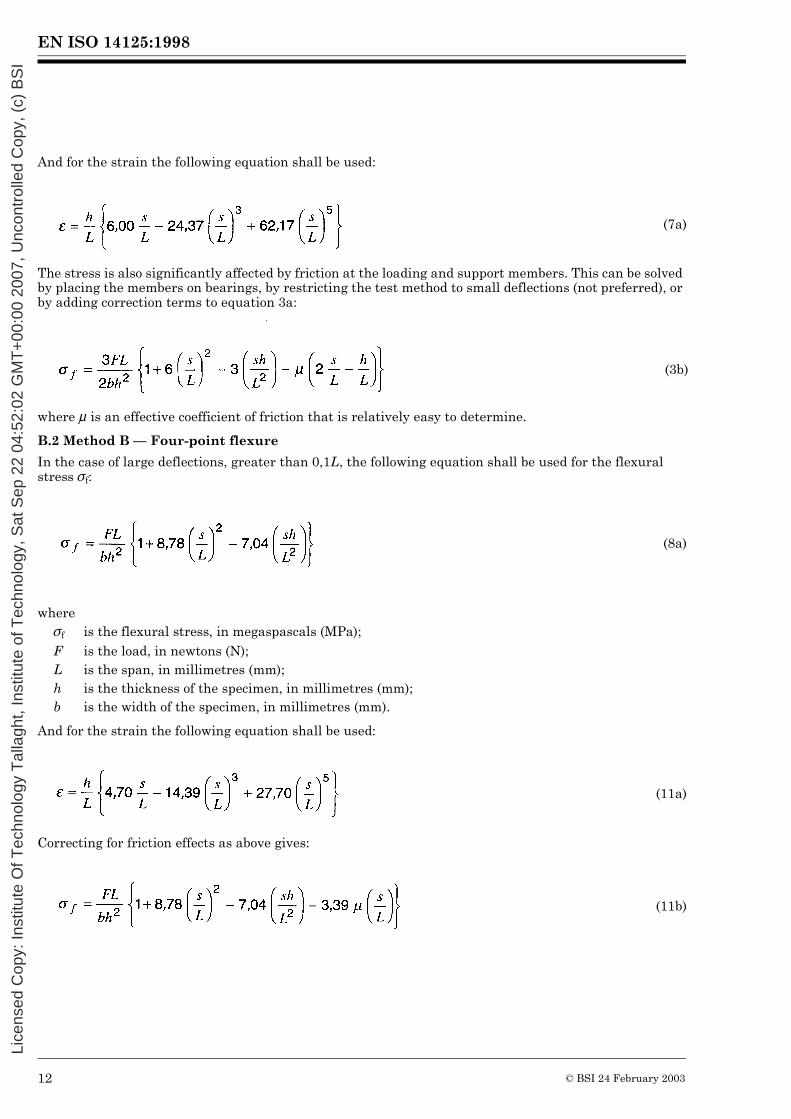
And for the strain the following equation shall be used:
The stress is also significantly affected by friction at the loading and support members. This can be solved by placing the members on bearings, by restricting the test method to small deflections (not preferred), or by adding correction terms to equation 3a:
where � is an effective coefficient of friction that is relatively easy to determine.
B.2 Method B — Four-point flexure
In the case of large deflections, greater than 0,1L, the following equation shall be used for the flexural stress �f:
And for the strain the following equation shall be used:
Correcting for friction effects as above gives:
(7a)
(3b)
(8a)
where�f is the flexural stress, in megaspascals (MPa);F is the load, in newtons (N);L is the span, in millimetres (mm);h is the thickness of the specimen, in millimetres (mm);b is the width of the specimen, in millimetres (mm).
(11a)
(11b)
Lice
nsed
Cop
y: In
stitu
te O
f Tec
hnol
ogy
Tal
lagh
t, In
stitu
te o
f Tec
hnol
ogy,
Sat
Sep
22
04:5
2:02
GM
T+
00:0
0 20
07, U
ncon
trol
led
Cop
y, (
c) B
SI
EN ISO 14125:1998
© BSI 24 February 2003 13
Figure 1 — Typical stress-strain curve (N.B. Strains �´ and �´´ are equivalent to displacements s´ � and s´´, respectively)
Figure 2 — Unidirectional reinforced composite plate element showing symmetry axes
Lice
nsed
Cop
y: In
stitu
te O
f Tec
hnol
ogy
Tal
lagh
t, In
stitu
te o
f Tec
hnol
ogy,
Sat
Sep
22
04:5
2:02
GM
T+
00:0
0 20
07, U
ncon
trol
led
Cop
y, (
c) B
SI

EN ISO 14125:1998
14 © BSI 24 February 2003
Figure 3 — Three-point loading arrangement
Figure 4 — Four-point loading arrangement (N.B. L = 3L´ �)
Lice
nsed
Cop
y: In
stitu
te O
f Tec
hnol
ogy
Tal
lagh
t, In
stitu
te o
f Tec
hnol
ogy,
Sat
Sep
22
04:5
2:02
GM
T+
00:0
0 20
07, U
ncon
trol
led
Cop
y, (
c) B
SI
EN ISO 14125:1998
© BSI 24 February 2003 15
Figure 5 — Location of specimens
Lice
nsed
Cop
y: In
stitu
te O
f Tec
hnol
ogy
Tal
lagh
t, In
stitu
te o
f Tec
hnol
ogy,
Sat
Sep
22
04:5
2:02
GM
T+
00:0
0 20
07, U
ncon
trol
led
Cop
y, (
c) B
SI

EN ISO 14125:1998
16 © BSI 24 February 2003
Figure 6 — Examples of possible failure modes (Tensile-initiated and compression-initiated, remote from the loading points, are acceptable failure
modes. Failures initiated by interlaminar shear are not acceptable.)
Lice
nsed
Cop
y: In
stitu
te O
f Tec
hnol
ogy
Tal
lagh
t, In
stitu
te o
f Tec
hnol
ogy,
Sat
Sep
22
04:5
2:02
GM
T+
00:0
0 20
07, U
ncon
trol
led
Cop
y, (
c) B
SI

blank
Lice
nsed
Cop
y: In
stitu
te O
f Tec
hnol
ogy
Tal
lagh
t, In
stitu
te o
f Tec
hnol
ogy,
Sat
Sep
22
04:5
2:02
GM
T+
00:0
0 20
07, U
ncon
trol
led
Cop
y, (
c) B
SI

BS EN ISO 14125:1998
BSI
389 Chiswick High Road
London
W4 4AL
BSI — British Standards InstitutionBSI is the independent national body responsible for preparing British Standards. It presents the UK view on standards in Europe and at the international level. It is incorporated by Royal Charter.
Revisions
British Standards are updated by amendment or revision. Users of British Standards should make sure that they possess the latest amendments or editions.
It is the constant aim of BSI to improve the quality of our products and services. We would be grateful if anyone finding an inaccuracy or ambiguity while using this British Standard would inform the Secretary of the technical committee responsible, the identity of which can be found on the inside front cover. Tel: +44 (0)20 8996 9000. Fax: +44 (0)20 8996 7400.
BSI offers members an individual updating service called PLUS which ensures that subscribers automatically receive the latest editions of standards.
Buying standards
Orders for all BSI, international and foreign standards publications should be addressed to Customer Services. Tel: +44 (0)20 8996 9001. Fax: +44 (0)20 8996 7001. Email: [email protected]. Standards are also available from the BSI website at http://www.bsi-global.com.
In response to orders for international standards, it is BSI policy to supply the BSI implementation of those that have been published as British Standards, unless otherwise requested.
Information on standards
BSI provides a wide range of information on national, European and international standards through its Library and its Technical Help to Exporters Service. Various BSI electronic information services are also available which give details on all its products and services. Contact the Information Centre. Tel: +44 (0)20 8996 7111. Fax: +44 (0)20 8996 7048. Email: [email protected].
Subscribing members of BSI are kept up to date with standards developments and receive substantial discounts on the purchase price of standards. For details of these and other benefits contact Membership Administration. Tel: +44 (0)20 8996 7002. Fax: +44 (0)20 8996 7001. Email: [email protected].
Information regarding online access to British Standards via British Standards Online can be found at http://www.bsi-global.com/bsonline.
Further information about BSI is available on the BSI website at http://www.bsi-global.com.
Copyright
Copyright subsists in all BSI publications. BSI also holds the copyright, in the UK, of the publications of the international standardization bodies. Except as permitted under the Copyright, Designs and Patents Act 1988 no extract may be reproduced, stored in a retrieval system or transmitted in any form or by any means – electronic, photocopying, recording or otherwise – without prior written permission from BSI.
This does not preclude the free use, in the course of implementing the standard, of necessary details such as symbols, and size, type or grade designations. If these details are to be used for any other purpose than implementation then the prior written permission of BSI must be obtained.
Details and advice can be obtained from the Copyright & Licensing Manager. Tel: +44 (0)20 8996 7070. Fax: +44 (0)20 8996 7553. Email: [email protected].
Lice
nsed
Cop
y: In
stitu
te O
f Tec
hnol
ogy
Tal
lagh
t, In
stitu
te o
f Tec
hnol
ogy,
Sat
Sep
22
04:5
2:02
GM
T+
00:0
0 20
07, U
ncon
trol
led
Cop
y, (
c) B
SI