Fibre Orientation and Related Headbox Optimization...
12
Fibre Orientation and Related Headbox Optimization Systems Headbox Optimization Systems Jari Hämäläinen C t fC t ti lE i i dIt tdD i (CEID) Centre of Computational Engineering and Integrated Design (CEID) Lappeenranta University of Technology (LUT) Lappeenranta, Finland
Transcript of Fibre Orientation and Related Headbox Optimization...

Fibre Orientation and Related Headbox Optimization SystemsHeadbox Optimization Systems
Jari Hämäläinen
C t f C t ti l E i i d I t t d D i (CEID)Centre of Computational Engineering and Integrated Design (CEID)Lappeenranta University of Technology (LUT)Lappeenranta, Finland

Fibre OrientationFibre Orientation
− Basic fibrous structure of the paper sheet is formed at the wet end of a paper machine -headbox and forming section
− Fibre orientation (angle and anisotropy) determines the dimensional stability of the paperdetermines the dimensional stability of the paper
− Velocity gradients align fibres whereas turbulence makes orientation more random
Nancy, 13-14 October, 2011 2www.lut.fi/ceid

Fibre Orientation, its Anisotropy d CD A l P filand CD Angle Profile
− Fibre orientation distribution in each location
− The average fibre orientation angle profile in cross direction (CD) of a paper machine
Nancy, 13-14 October, 2011 3www.lut.fi/ceid

Modelling of Fibre Orientation P b bilit Di t ib ti (FOPD)Probability Distribution (FOPD)
J/W=0.9(d )(drag)
J/W 1 1J/W=1.1(rush)
J/W=1.0(“tasaperä”)
J=Jet speedW=wire speed
Nancy, 13-14 October, 2011 www.lut.fi/ceid 4
Niskanen, Hämäläinen (2011), NPPRJ (in press)

CFD-based Optimization for Fib O i t ti A l P filFibre Orientation Angle Profiles
− Optimal shape design of the tapered header to get even flow distribution
− Optimal control of the slice opening to avoid CD velocities in the jet
− Based on depth-averaged NS equations
Nancy, 13-14 October, 2011 5www.lut.fi/ceid
− Software tools developed to industry
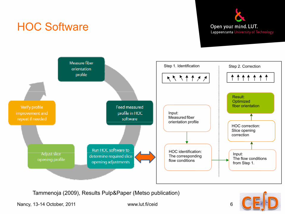
HOC SoftwareHOC Software
Step 2. CorrectionStep 1. Identification
Input:Measured fiberorientation profile
Result:Optimizedfiber orientation
orientation profile
HOC identification: I t
HOC correction:Slice openingcorrection
HOC identification:The correspondingflow conditions
Input:The flow conditionsfrom Step 1.
Nancy, 13-14 October, 2011 6www.lut.fi/ceid
Tammenoja (2009), Results Pulp&Paper (Metso publication)

HOC SoftwareE t l F t CFD M d lExtremely Fast CFD Model
Step 1: identification Step 2: correction
CFD model inside HOC software:− 2D, laminar, depth-averaged− 5 000 elements (stabilized FEM)
3D CFD (ANSYS-CFX):− 3D, turbulent, free jet− 2-3 million cells( )
− CPU time is 5 seconds2 3 million cells
− CPU time is 1 hourNancy, 13-14 October, 2011 7www.lut.fi/ceid

HOC SoftwareMill E l AMill Example A
12 0Before optimization After optimization
6.0
8.0
10.0
12.0
[°]
0.0
2.0
4.0
atio
n an
gle
8 0
-6.0
-4.0
-2.0
Orie
nta
-12.0
-10.0
-8.0
CD positionCD position• Max‐Min orientation range = 20 degrees before optimization
Nancy, 13-14 October, 2011 8www.lut.fi/ceid

HOC Software Mill l BMill example B
Before optimization After optimization
4 0
6,0
8,0
°]
Before optimization After optimization
0,0
2,0
4,0
n an
gle
[°
-4,0
-2,0
Orie
ntat
ion
-8,0
-6,0
0 0,1 0,2 0,3 0,4 0,5 0,6 0,7 0,8 0,9 1
O
Nancy, 13-14 October, 2011 9www.lut.fi/ceid
Normalized CD position

More than 50 paper machine h db ti i d fheadboxes optimized so far
Nancy, 13-14 October, 2011 10www.lut.fi/ceid
Avikainen, Hämäläinen, Tarvainen (2010), NPPRJ, 25(4)

Conclusion: Different Modelling A h f Diff t PApproaches for Different Purposes
− One-phase model (pure water)− Meter-scale phenomena in
headbox− Routine CFD analyses
− Rheological model (effective medium)del com
plexity
Flocculation g ( )− Head losses in pipes, stock
preparation processes, MC,..− No large concentration variations
Passive scalar (one way coupling)
Mod
Flocculation
− Passive scalar (one-way coupling) − Dilute suspensions− Fibre orientation probability distr.
− Two-phase flow (two-way coupling)
Fibre orientation
p ( y p g)− Carrying phase (water) and
dispersed phase (fibres or flocs) handled separately
− Concentration variations slipConcentration variations, slip velocity between the phases,...
Nancy, 13-14 October, 2011 www.lut.fi/ceid 11"Model reality"

References and Acknowledgementse e e ces a d c o edge e ts
− Fibre Orientation Probability Distribution (FOPD) modelling( ) ( )− Doctoral theses by T. Hämäläinen (2008) and H. Niskanen (2011)
− Niskanen et al., IJMF (2011)− Hämäläinen et al., J.Eng.Math. (2011)− Niskanen Hämäläinen NPPRJ (in press)Niskanen, Hämäläinen, NPPRJ (in press)− Other authors from KTH, UBC, etc.
− CFD-based Optimization− Hämäläinen et al. in “Optimization and Computational Fluid
D i ” Th i J i (2008)Dynamics”, Thevenin, Janiga (2008)− Avikainen et al., NPPRJ (2010)
− AcknowledgementsAcknowledgements− CFD-based optimization software tools have been developed since
1995 at University of Jyväskylä, VTT, Metso (Valmet) and Numerola− Thanks to Paper Physics Group at University of Eastern Finland,
Kuopio for the results of FOPD modelling in 2004 2011Kuopio for the results of FOPD modelling in 2004-2011
Nancy, 13-14 October, 2011 12www.lut.fi/ceid