Fiberglass (FRP) Sunshades & Windwalls 03 21 NE
7
Transcript of Fiberglass (FRP) Sunshades & Windwalls 03 21 NE


02
ICE engineers have designed many FRP Sunshades and Windwalls—primarily for offshore Trinidad, The trade winds are blowing constantly with wind speeds upwards of 35-40 mph (55-65 km/hour) producing a continual salt spray that quickly causes topsides corrosion of the offshore platforms structural steel and production equipment. These windwalls, initia-lly, were manufactured using steel beams with corrugated steel plate, with the corrugated steel plate attached to the steel columns and crossbeams with the use of self-tapping screws. This obviously led to immediate corrosion—at every self-tapping screw there was rust bleeding down the corrugated steel plate making the walls very unattractive.
ICE engineers convinced BP Trinidad & Tobago, Enron Trinidad and EOG Trinidad to try the all-FRP option back in the early-to-mid 1990s, and from that point on, all windwalls have been all-FRP. The columns supporting the windwalls are FRP shapes, the crossbeams supporting the corrugated sheathing are FRP, and the corrugated sheathing is FRP. To further eliminate corrosion, 316 SS fasteners are also used.
There are steel weldments that are required to affix the FRP windwall/sunshade panels to the carbon steel deck edge beams—both at the top and at the bottom, and these weldments are typically 316 SS. The mounting plate possessing holes for bolting the FRP panels should always be 316 SS. If you want corrosion offshore, put a hole in a carbon steel plate. It is ICE’s philosophy to never put a bolt hole in a carbon steel plate—we always recommend that any plate possessing a bolt hole be 316 SS bolt hole be 316 SS, and further that the bolting hardware be 316 SS.
Not all windwalls are solid. On many occasions, we have employed fixed, louvered panels that allow air flow through the walls, especially for gas platforms. For Aramco, where the ambient heat can be extraordinarily high—135-140˚F (60˚C), the FRP panels serve a diffe-rent purpose—to provide shade and protection for the production equipment and personnel from the extreme temperatures. Having air flow is very important in this situation and as such, the fixed, louvered FRP sunshade panels are more desirable
When designing an FRP sunshade, the structural engineer must know the following:• The 100-year design storm windspeed• The seismic accelerations vertically and horizontally• The transportation accelerations—pitch, roll and heave
For the Gulf of Mexico, where the FRP walls are exposed to hurricane winds, the wind loading typically controls. For most applications, in the gulf of mexico we design the FRP walls for a hurricane windspeed of 165 miles/hour (266 km/hour = 74 m/sec). For an offsho-re platform, per the ASCE’s definition, the Exposure Category is Category D—flat, unobstruc-ted areas exposed to wind flowing over open water for a distance of at least 1 mile (1.6 km)—the fetch.
03
When analyzing for the seismic and transportation cases, the engineer shall also apply an operating wind speed on top of the acceleration forces typically 50 miles/hour (23 m/s).
Taken from the American Society of Civil Engineers (ASCE) Minimum Design Loads for Buildings and other Structures, the wind pressure, p, is calculated using the Imperial formula:
p = 0.00256*Kz*Kzt*V2*I*Cs, where:
p = design wind pressure, lbs/ft2
Kz = Velocity Pressure Coefficient evaluated at height z. Typically for an offshore platform, z ranges from the 30 feet elevation (9.1 m) where Kz = 1.16 up to an elevation of 100 feet (30.5 m) where Kz =1.43. Linear interpolation can be used for elevation between these two elevations.
Kzt = Topographic Constant = 1.0 for an offshore platform
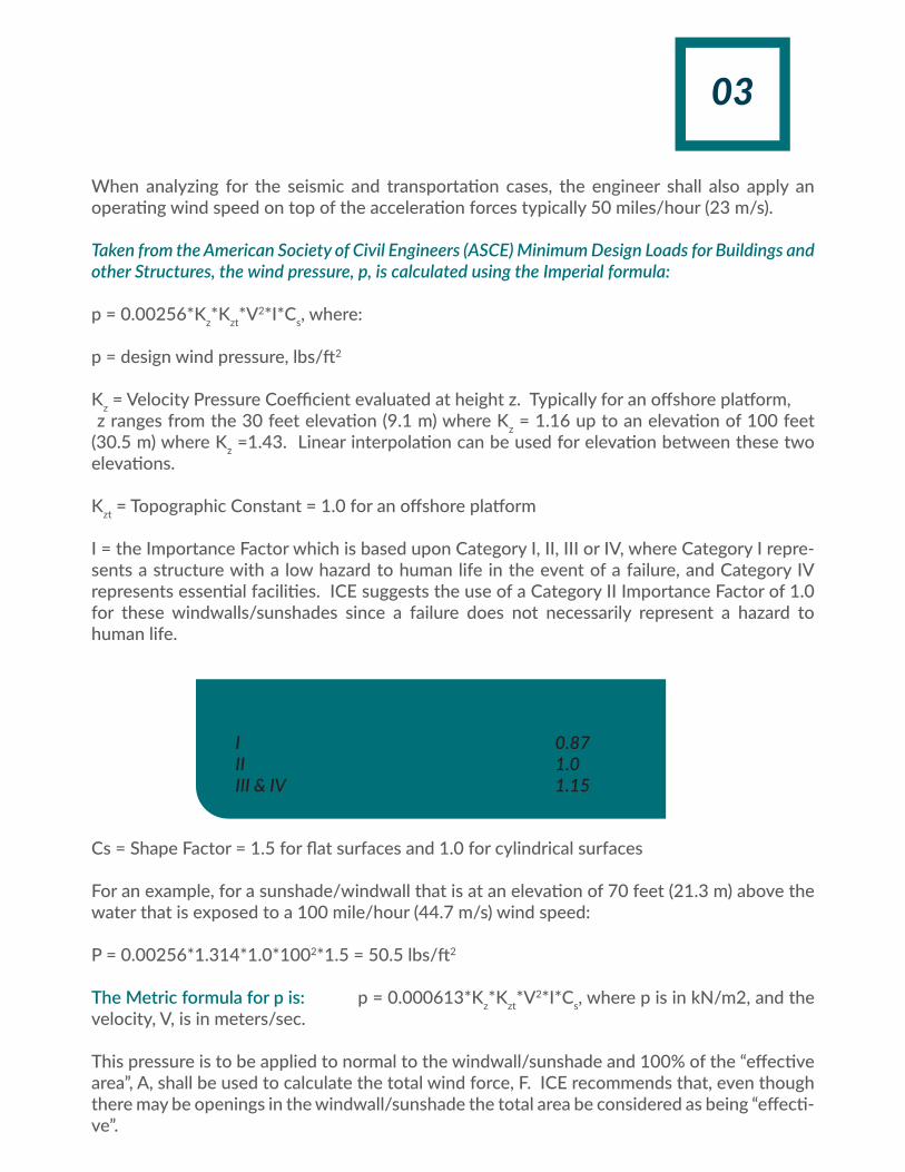
I = the Importance Factor which is based upon Category I, II, III or IV, where Category I repre-sents a structure with a low hazard to human life in the event of a failure, and Category IV represents essential facilities. ICE suggests the use of a Category II Importance Factor of 1.0 for these windwalls/sunshades since a failure does not necessarily represent a hazard to human life.
Cs = Shape Factor = 1.5 for flat surfaces and 1.0 for cylindrical surfaces
For an example, for a sunshade/windwall that is at an elevation of 70 feet (21.3 m) above the water that is exposed to a 100 mile/hour (44.7 m/s) wind speed:
P = 0.00256*1.314*1.0*1002*1.5 = 50.5 lbs/ft2
The Metric formula for p is: p = 0.000613*Kz*Kzt*V2*I*Cs, where p is in kN/m2, and the velocity, V, is in meters/sec.
This pressure is to be applied to normal to the windwall/sunshade and 100% of the “effective area”, A, shall be used to calculate the total wind force, F. ICE recommends that, even though there may be openings in the windwall/sunshade the total area be considered as being “effecti-ve”.
Category Importance Factor
I 0.87II 1.0III & IV 1.15

04WarrantyICE provides a 25-year warranty against structural defects, ultra-violet deterioration, crafts-manship and performance of its’ windwall/sunshades. To provide an extra barrier for UV protection, ICE recommends painting the windwall/sunshade with a urethane paint after fabrication and assembly. Abrade the surfaces of the windwall/sunshade to create an anchor profile by sand blasting or grinding the surfaces (100%) and then apply per manufac-turer’s recommendations the urethane coating.
Lifting EyesEach windwall/sunshade panel shall be equipped with a set of lifting lugs (or lifting eyes). Each padeye shall be designed for the entire weight of the windwall/sunshade panel, plus an impact factor of 2.0 shall also be applied. ICE recommends that the padeye material be 316 SS to prevent the possibility of corrosion for lifts that may be necessary in the future.
Structural AnalysisOnce the appropriate wind loads/forces are determined, the columns and crossbeams shall be sized in accordance with the ICE Structural Fiberglass Design Manual. Deflection of windwall/sunshade panels is typically of no concern, but the engineer must verify that the columns and crossbeams do not suffer from local buckling or Euler buckling. A 1/3rd increase in allowable stresses is not permit-ted—even for the storm wind condition. In accordance with the ICE Structural Fiberglass Design Manual, the following Safety Factors must be adhered to:
Type of Stress Safety Factor
Flexure 2.5
Compression
Tension
3.0
2.5
Beam Shear 3.0
Connections (Local Shear & Bearing) 4.0

05
As with all FRP structures, the effects of temperature should be incorporated into the analy-sis. A vinyl ester resin is more heat resistant than an isophthalic polyester. The following Reduction Factors for Modulus of Elasticity and Strength shall be incorporated:
In all instances, only isophthalic polyester or vinyl ester material possessing an ASTM E84 Flame Spread Rating (FSR) of 25 or less shall be used. The lower the FSR, the more fire retar-dant the material is.
Fire Retardant Materials
Temperature
Strength Retention Factors (Ts)
80° F (26.6° C)
100° F (37.8° C)
125° F (51.7° C)
150°F (65.6° C)
175° F (79.4° C)
200° F (93.3° C)
Isophthalic Polyester
100% (1.0)
85% (0.85)
70% (0.7)
50% (0.5)
Not Recommended
Not Recommended
Vinyl Ester
100% (1.0)
90% (.9)
80% (0.8)
80% (0.8)
75% (0.75)
50% (0.5)
Temperature
Modulus of Elasticity Retention Factors (Tm)
80° F (26.6° C)
100° F (37.8° C)
125° F (51.7° C)
150°F (65.6° C)
175° F (79.4° C)
200° F (93.3° C)
Isophthalic Polyester
100% (1.0)
100% (1.0)
90% (0.9)
85% (0.85)
Not Recommended
Not Recommended
Vinyl Ester
100% (1.0)
100% (1.0)
95% (0.95)
90% (0.9)
88% (0.88)
85% (0.85)

FSW 03 21
Ingenium Composites & Elastomers, LLC.11010 Neeshaw Dr. Bldg B
Houston, Texas 77065USA
Telephone: +1-832-674-4825E-mail: [email protected]
Cs = Shape Factor = 1.5 for flat surfaces and 1.0 for cylindrical surfaces
For an example, for a sunshade/windwall that is at an elevation of 70 feet (21.3 m) above the water that is exposed to a 100 mile/hour (44.7 m/s) wind speed:
P = 0.00256*1.314*1.0*1002*1.5 = 50.5 lbs/ft2
The Metric formula for p is: p = 0.000613*Kz*Kzt*V2*I*Cs, where p is in kN/m2, and the velocity, V, is in meters/sec.
This pressure is to be applied to normal to the windwall/sunshade and 100% of the “effective area”, A, shall be used to calculate the total wind force, F. ICE recommends that, even though there may be openings in the windwall/sunshade the total area be considered as being “effecti-ve”.