Fiber Optic Systems II Cable Design - PDHonline.com
29
An Approved Continuing Education Provider PDHonline Course E309 (3 PDH) Fiber Optic Systems II – Cable Design Instructor: Lee Layton, P.E 2013 PDH Online | PDH Center 5272 Meadow Estates Drive Fairfax, VA 22030-6658 Phone & Fax: 703-988-0088 www.PDHonline.org
Transcript of Fiber Optic Systems II Cable Design - PDHonline.com
An Approved Continuing Education Provider
PDHonline Course E309 (3 PDH)
Fiber Optic Systems II – Cable Design
Instructor: Lee Layton, P.E
2013
PDH Online | PDH Center
5272 Meadow Estates Drive
Fairfax, VA 22030-6658
Phone & Fax: 703-988-0088
www.PDHonline.org

www.PDHcenter.com PDH Course E309 www.PDHonline.org
Page 2 of 29
Fiber Optic Systems II – Cable Design
Lee Layton, P.E
Table of Contents
Section Page
Preface ……………………………….….. 3
Introduction ………………………….….. 4
Chapter 1 – Optical Fiber Designs …..….. 5
Chapter 2 – Optical Cable Design ………. 16
Summary ……………………………….. 28
This series of courses are based on the Navy Electricity and Electronics
Training Series (NEETS) section on Fiber Optic cable systems. The NEETS
material has been reformatted for readability and ease of use as a continuing
education course. The NEETS series is produced by the Naval Education and
Training Professional Development and Technology Center.

www.PDHcenter.com PDH Course E309 www.PDHonline.org
Page 3 of 29
Preface
This is the first in a series of five courses about fiber optic cable systems. The series covers fiber
optics from basic light theory transmission to cables, connectors, testing, and signal transmission.
The complete series includes these five courses:
1. Fiber Optics I – Theory
2. Fiber Optics II – Cable Design
3. Fiber Optics III – Connectors
4. Fiber Optics IV – Testing
5. Fiber Optics V – Equipment
The first course, Fiber Optics I –Theory, is an overview of the technology of fiber optic cables
including a description of the components, history, and advantages of fiber optic cables. This
course also discusses the electromagnetic theory of light and describes the properties of light
reflection, refraction, diffusion, and absorption.
The second course, Fiber Optics II – Cable Design, explains the basic construction of fiber optic
cables including the types of cables, cable properties, and performance characteristics. The
course reviews multimode, single mode step-index and graded index fibers, and fabrication
procedures.
The third course, Fiber Optics III - Connectors, describes fiber optic splices, connectors,
couplers and the types of connections they form in systems. It includes a discussion on the types
of extrinsic and intrinsic coupling losses, fiber alignment and fiber mismatch problems, and fiber
optic mechanical and fusion splices.
The fourth course, Fiber Optics IV - Testing, describes the optical fiber and optical connection
laboratory measurements used to evaluate fiber optic components and system performance,
including the near-field and far-field optical power distribution of an optical fiber. This course
also reviews optical time-domain reflectometry (OTDR).
The fifth course, Fiber Optics V - Equipment, explains the principal properties of an optical
source and fiber optic transmitters, the optical emission properties of semiconductor light-
emitting diodes (LEDs) and laser diodes (LDs), and explains the operational differences between
surface-emitting LEDs (SLEDs), edge-emitting LEDs (ELEDs), superluminescent diodes
(SLDs), and laser diodes.
It is not necessary to take the courses in sequence. However, for best comprehension it is
suggested that the courses be taken in the order presented.

www.PDHcenter.com PDH Course E309 www.PDHonline.org
Page 4 of 29
Introduction
This is Volume II of five volumes on fiber optics systems. This volume is concerned with the
basic design of fiber optic cables. Optical fibers are thin cylindrical dielectric (non-conductive)
waveguides used to send light energy for communication. Optical fibers consist of three parts:
the core, the cladding, and the coating or buffer.
This course describes multimode and single mode step-index and graded-index fibers, explains
the terms refractive index profile, relative refractive index difference, and profile parameter and
lists the performance advantages of multimode graded-index fibers.
The choice of optical fiber materials and fiber design depends on operating conditions and
intended application. Optical fibers are protected from the environment by incorporating the
fiber into some type of cable structure. Cable strength members and outer jackets protect the
fiber. Optical cable structure and material composition depend on the conditions of operation and
the intended application.
The course also describes fabrication processes including the vapor phase oxidation and direct-
melt optical fiber fabrication procedures. Basic cable components, such as buffers, strength
members, and jacket materials are explained as well as the advantages and disadvantages of
OFCC cable, stranded cable, and ribbon cable designs.

www.PDHcenter.com PDH Course E309 www.PDHonline.org
Page 5 of 29
Chapter One
Optical Fiber Designs
Optical fibers are either single mode or multimode fibers. Fibers are classified according to the
number of modes that they can propagate. Single mode fibers can propagate only the
fundamental mode. Multimode fibers can propagate hundreds of modes. However, the
classification of an optical fiber depends on more than the number of modes that a fiber can
propagate.
An optical fiber's refractive index profile and core size further distinguish single mode and
multimode fibers. The refractive index profile describes the value of refractive index as a
function of radial distance at any fiber diameter. Fiber refractive index profiles classify single
mode and multimode fibers as follows:
Multimode step-index fibers
Multimode graded-index fibers
Single mode step-index fibers
Single mode graded-index fibers
In a step-index fiber, the refractive index of the core is uniform and undergoes an abrupt change
at the core-cladding boundary. Step-index fibers obtain their name from this abrupt change called
the step change in refractive index. In graded-index fibers, the refractive index of the core varies
gradually as a function of radial distance from the fiber center.
Single mode and multimode fibers can have a step-index or graded-index refractive index
profile. The performance of multimode graded-index fibers is usually superior to multimode
step-index fibers. However, each type of multimode fiber can improve system design and
operation depending on the intended application. Performance advantages for single mode
graded-index fibers compared to single mode step-index fibers are relatively small. Therefore,
single mode fiber production is almost exclusively step-index. Figure 1 shows the refractive
index profile for a multimode step-index fiber and a multimode graded-index fiber. Figure 1 also
shows the refractive index profile for a single mode step-index fiber. Since light propagates
differently in each fiber type the figure also shows the propagation of light along each fiber.

www.PDHcenter.com PDH Course E309 www.PDHonline.org
Page 6 of 29
Figure 1. - The refractive index profiles and light propagation in multimode step-index,
multimode graded-index, and single mode step-index fibers.
Fiber core size and material composition can affect system performance. A small change in core
size and material composition affects fiber transmission properties, such as attenuation and
dispersion.
When selecting an optical fiber, the system designer decides which fiber core size and material
composition is appropriate.
Standard core sizes for multimode step-index fibers are 50 m and 100 m. Standard core sizes
for multimode graded-index fibers are 50 m, 62.5 m, 85 m, and 100 m. Standard core sizes
for single mode fibers are between 8 m and 10 m. In most cases, the material used in the preparation of optical fibers is high-quality glass (SiO2).

www.PDHcenter.com PDH Course E309 www.PDHonline.org
Page 7 of 29
This glass contains very low amounts of impurities, such as water or elements other than silica
and oxygen. Using high-quality glass produces fibers with low losses. Small amounts of some
elements other than silica and oxygen are added to the glass material to change its index of
refraction. These elements are called material dopants. Silica doped with various materials forms
the refractive index profile of the fiber core and material dopants are discussed in more detail
later. Glass is not the only material used in fabrication of optical fibers. Plastics are also used
for core and cladding materials in some applications.
A particular optical fiber design can improve fiber optic system performance.
Each single mode or multimode, step-index or graded-index, glass or plastic, or large or small
core fiber has an intended application. The system designer must choose an appropriate fiber
design that optimizes system performance in his application.
Multimode Step-Index Fibers
A multimode step-index fiber has a core of radius (a) and a constant refractive index n1. A
cladding of slightly lower refractive index n2 surrounds the core. Figure 2 shows the refractive
index profile n(r) for this type of fiber. n(r) is equal to n1 at radial distances r < a (core). The
refractive index profile, n(r), is equal to n2 at radial distances r > a (cladding). Notice the step
decrease in the value of refractive index at the core-cladding interface.
Figure 2. - The refractive index profile for multimode step-index fibers.
This step decrease occurs at a radius equal to distance (a). The difference in the core and
cladding refractive index is the parameter delta (,

www.PDHcenter.com PDH Course E309 www.PDHonline.org
Page 8 of 29
=
Where,
= The relative refractive index difference. n1 = Core refractive index.
n2 = Cladding refractive index.
The ability of the fiber to accept optical energy from a light source is related to delta (. Delta
( also relates to the numerical aperture by,
A ~
Where,
NA = Numerical aperture.
= Relative refractive index.
n1 = Core refractive index.
The number of modes that multimode step-index fibers propagate depends on delta ( and core
radius (a) of the fiber. The number of propagating modes also depends on the wavelength () of the transmitted light.
In a typical multimode step-index fiber, there are hundreds of propagating modes.
Most modes in multimode step-index fibers propagate far from cutoff.
Modes that are cut off cease to be bound to the core of the fiber. Modes that are farther away
from the cutoff wavelength concentrate most of their light energy into the fiber core. Modes that
propagate close to cutoff have a greater percentage of their light energy propagate in the
cladding. Since most modes propagate far from cutoff, the majority of light propagates in the
fiber core.
Therefore, in multimode step-index fibers, cladding properties, such as cladding diameter, have
limited affect on mode (light) propagation.
Multimode step-index fibers have relatively large core diameters and large numerical apertures.
A large core size and a large numerical aperture make it easier to couple light from a light-
emitting diode (LED) into the fiber. Multimode step-index fiber core size is typically 50 m or
100 m.
Unfortunately, multimode step-index fibers have limited bandwidth capabilities.

www.PDHcenter.com PDH Course E309 www.PDHonline.org
Page 9 of 29
Dispersion, mainly modal dispersion, limits the bandwidth or information-carrying capacity of
the fiber. System designers consider each factor when selecting an appropriate fiber for each
particular application.
Multimode step-index fiber selection depends on system application and design. Short-haul,
limited bandwidth, low-cost applications typically use multimode step-index fibers.
Multimode Graded-Index Fibers
A multimode graded-index fiber has a core of radius (a). Unlike step-index fibers, the value of
the refractive index of the core (n1) varies according to the radial distance (r). The value of n1
decreases as the distance (r) from the center of the fiber increases.
The value of n1 decreases until it approaches the value of the refractive index of the cladding
(n2). The value of n1 must be higher than the value of n2 to allow for proper mode propagation.
Like the step-index fiber, the value of n2 is constant and has a slightly lower value than the
maximum value of n1. The relative refractive index difference () is determined using the maximum value of n1 and the value of n2.
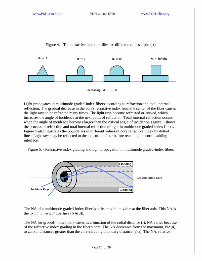
Figure 3 shows a possible refractive index profile n(r) for a multimode graded-index fiber.
Notice the parabolic refractive index profile of the core. The profile parameter alpha ()
determines the shape of the core's profile. As the value of alpha increases, the shape of the core's profile changes from a triangular shape to step as shown in Figure 4. Most multimode
graded-index fibers have a parabolic refractive index profile. Multimode fibers with near
parabolic graded-index profiles provide the best performance. Unless otherwise specified, when
discussing multimode graded-index fibers, assume that the core's refractive index profile is
parabolic (=2).
Figure 3. - The refractive index profile for multimode graded-index fibers.
www.PDHcenter.com PDH Course E309 www.PDHonline.org
Page 10 of 29
Figure 4. - The refractive index profiles for different values alpha.
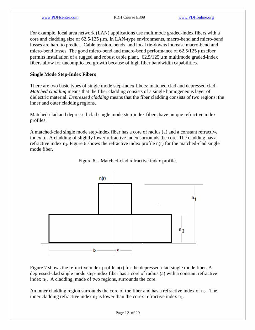
Light propagates in multimode graded-index fibers according to refraction and total internal
reflection. The gradual decrease in the core's refractive index from the center of the fiber causes
the light rays to be refracted many times. The light rays become refracted or curved, which
increases the angle of incidence at the next point of refraction. Total internal reflection occurs
when the angle of incidence becomes larger than the critical angle of incidence. Figure 5 shows
the process of refraction and total internal reflection of light in multimode graded-index fibers.
Figure 5 also illustrates the boundaries of different values of core refractive index by dotted
lines. Light rays may be reflected to the axis of the fiber before reaching the core-cladding
interface.
Figure 5. - Refractive index grading and light propagation in multimode graded-index fibers.
The NA of a multimode graded-index fiber is at its maximum value at the fiber axis. This NA is
the axial numerical aperture (NA(0)).
The NA for graded-index fibers varies as a function of the radial distance (r). NA varies because
of the refractive index grading in the fiber's core. The NA decreases from the maximum, NA(0),
to zero at distances greater than the core-cladding boundary distance (r>a). The NA, relative

www.PDHcenter.com PDH Course E309 www.PDHonline.org
Page 11 of 29
refractive index difference (), profile parameter (), and normalized frequency (V) determine
the number of propagating modes in multimode graded-index fibers. A multimode graded-index
fiber with the same normalized frequency as a multimode step-index fiber will have approximately one-half as many propagating modes. However, multimode graded-index fibers
typically have over one-hundred propagating modes.
Multimode graded-index fibers accept less light than multimode step-index fibers with the same
core delta (. However, graded-index fibers usually outperform the step-index fibers. The
core's parabolic refractive index profile causes multimode graded-index fibers to have less modal
dispersion.
Figure 5 shows possible paths that light may take when propagating in multimode graded-index
fibers. Light rays that travel farther from the fiber's axis travel a longer distance. Light rays that
travel farther from the center travel in core material with an average lower refractive index.
Light travels faster in a material with a lower refractive index. Therefore, those light rays that
travel the longer distance in the lower refractive index parts of the core travel at a greater average
velocity. This means that the rays that travel farther from the fiber's axis will arrive at each point
along the fiber at nearly the same time as the rays that travel close to the fiber's axis. The
decrease in time difference between light rays reduces modal dispersion and increases multimode
graded-index fiber bandwidth. The increased bandwidth allows the use of multimode graded-
index fibers in most applications.
Most present day applications that use multimode fiber use graded-index fibers. The basic
design parameters are the fiber's core and cladding size and delta (. Standard multimode
graded-index fiber core and cladding sizes are 50/125 m, 62.5/125 m, 85/125 m, and
100/140 m. Each fiber design has a specific that improves fiber performance. Typical values
of delta ( are around 0.01 to 0.02. Although no single multimode graded-index fiber design is
appropriate for all applications, the 62.5/125 m fiber with a delta ( of 0.02 offers the best overall performance.
A multimode graded-index fiber's source-to-fiber coupling efficiency and insensitivity to micro-
bending and macro-bending losses are its most distinguishing characteristics. The fiber core size
and delta ( affect the amount of power coupled into the core and loss caused by microbending
and macro-bending. Coupled power increases with both core diameter and delta (, while
bending losses increase directly with core diameter and inversely with delta (. However, while
these values favor high delta (’s, a smaller delta ( improves fiber bandwidth.
In most applications, a multimode graded-index fiber with a core and cladding size of 62.5/125
m offers the best combination of the following properties:
Relatively high source-to-fiber coupling efficiency
Low loss
Low sensitivity to micro-bending and macro-bending
High bandwidth
Expansion capability
www.PDHcenter.com PDH Course E309 www.PDHonline.org
Page 12 of 29
For example, local area network (LAN) applications use multimode graded-index fibers with a
core and cladding size of 62.5/125 m. In LAN-type environments, macro-bend and micro-bend
losses are hard to predict. Cable tension, bends, and local tie-downs increase macro-bend and
micro-bend losses. The good micro-bend and macro-bend performance of 62.5/125 m fiber
permits installation of a rugged and robust cable plant. 62.5/125 m multimode graded-index
fibers allow for uncomplicated growth because of high fiber bandwidth capabilities.
Single Mode Step-Index Fibers
There are two basic types of single mode step-index fibers: matched clad and depressed clad.
Matched cladding means that the fiber cladding consists of a single homogeneous layer of
dielectric material. Depressed cladding means that the fiber cladding consists of two regions: the
inner and outer cladding regions.
Matched-clad and depressed-clad single mode step-index fibers have unique refractive index
profiles.
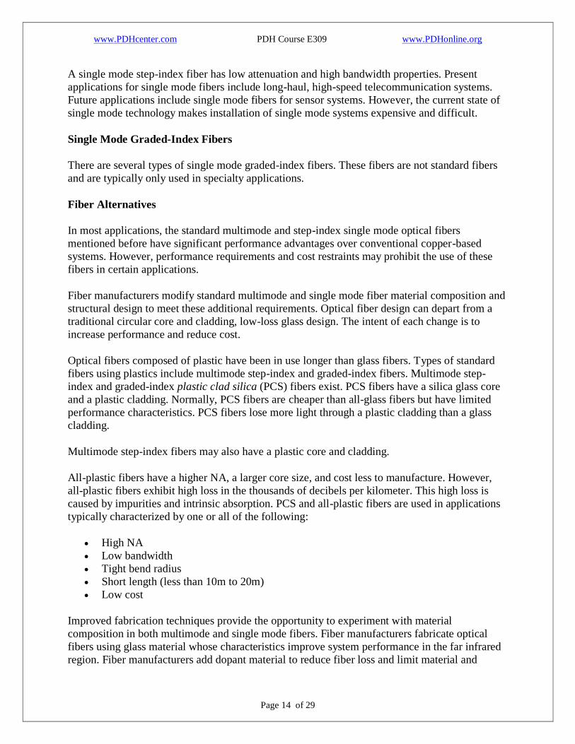
A matched-clad single mode step-index fiber has a core of radius (a) and a constant refractive
index n1. A cladding of slightly lower refractive index surrounds the core. The cladding has a
refractive index n2. Figure 6 shows the refractive index profile n(r) for the matched-clad single
mode fiber.
Figure 6. - Matched-clad refractive index profile.
Figure 7 shows the refractive index profile n(r) for the depressed-clad single mode fiber. A
depressed-clad single mode step-index fiber has a core of radius (a) with a constant refractive
index n1. A cladding, made of two regions, surrounds the core.
An inner cladding region surrounds the core of the fiber and has a refractive index of n2. The
inner cladding refractive index n2 is lower than the core's refractive index n1.

www.PDHcenter.com PDH Course E309 www.PDHonline.org
Page 13 of 29
An outer cladding region surrounds the inner cladding region and has a higher refractive index n3
than the inner cladding region. However, the outer cladding refractive index n3 is lower than the
core's refractive index n1.
Figure 7. - Depressed-clad refractive index profile.
Single mode step-index fibers propagate only one mode, called the fundamental mode. Single
mode operation occurs when the value of the fiber's normalized frequency (V) is between 0 and
2.405 (0 < V < 2.405). The value of V should remain near the 2.405 level. When the value of V
is less than one, single mode fibers carry a majority of the light power in the cladding material.
The portion of light transmitted by the cladding material easily radiates out of the fiber. For
example, light radiates out of the cladding material at fiber bends and splices.
Single mode fiber cutoff wavelength is the smallest operating wavelength when single mode
fibers propagate only the fundamental mode. At this wavelength, the second-order mode
becomes lossy and radiates out of the fiber core. As the operating wavelength becomes longer
than the cutoff wavelength, the fundamental mode becomes increasingly lossy.
The higher the operating wavelength is above the cutoff wavelength, the more power is
transmitted through the fiber cladding. As the fundamental mode extends into the cladding
material, it becomes increasingly sensitive to bending loss.
Single mode fiber designs include claddings of sufficient thickness with low absorption and
scattering properties to reduce attenuation of the fundamental mode. To increase performance
and reduce losses caused by fiber bending and splicing, fiber manufacturers adjust the value of
V. To adjust the value of V, they vary the core and cladding sizes and relative refractive index
difference ().
www.PDHcenter.com PDH Course E309 www.PDHonline.org
Page 14 of 29
A single mode step-index fiber has low attenuation and high bandwidth properties. Present
applications for single mode fibers include long-haul, high-speed telecommunication systems.
Future applications include single mode fibers for sensor systems. However, the current state of
single mode technology makes installation of single mode systems expensive and difficult.
Single Mode Graded-Index Fibers
There are several types of single mode graded-index fibers. These fibers are not standard fibers
and are typically only used in specialty applications.
Fiber Alternatives
In most applications, the standard multimode and step-index single mode optical fibers
mentioned before have significant performance advantages over conventional copper-based
systems. However, performance requirements and cost restraints may prohibit the use of these
fibers in certain applications.
Fiber manufacturers modify standard multimode and single mode fiber material composition and
structural design to meet these additional requirements. Optical fiber design can depart from a
traditional circular core and cladding, low-loss glass design. The intent of each change is to
increase performance and reduce cost.
Optical fibers composed of plastic have been in use longer than glass fibers. Types of standard
fibers using plastics include multimode step-index and graded-index fibers. Multimode step-
index and graded-index plastic clad silica (PCS) fibers exist. PCS fibers have a silica glass core
and a plastic cladding. Normally, PCS fibers are cheaper than all-glass fibers but have limited
performance characteristics. PCS fibers lose more light through a plastic cladding than a glass
cladding.
Multimode step-index fibers may also have a plastic core and cladding.
All-plastic fibers have a higher NA, a larger core size, and cost less to manufacture. However,
all-plastic fibers exhibit high loss in the thousands of decibels per kilometer. This high loss is
caused by impurities and intrinsic absorption. PCS and all-plastic fibers are used in applications
typically characterized by one or all of the following:
High NA
Low bandwidth
Tight bend radius
Short length (less than 10m to 20m)
Low cost
Improved fabrication techniques provide the opportunity to experiment with material
composition in both multimode and single mode fibers. Fiber manufacturers fabricate optical
fibers using glass material whose characteristics improve system performance in the far infrared
region. Fiber manufacturers add dopant material to reduce fiber loss and limit material and
www.PDHcenter.com PDH Course E309 www.PDHonline.org
Page 15 of 29
structural imperfections. Fiber material used in fabrication of low-loss, long wavelength optical
fibers includes the following:
Heavy-metal fluorides (such as zirconium and beryllium fluoride)
Chalcogenide glasses (such as arsenic/sulfur)
Crystalline materials (such as silver bromide and silver chloride)
In some applications stringent environmental requirements dictate the design of special optical
fibers. In some cases, manufacturers hermetically coat optical fibers to increase survivability and
reliability in high-moisture and high-strain environments. Manufacturers also design radiation-
hard fibers for nuclear power, space, and military systems. Radiation resistant fibers operate after
exposure to nuclear radiation. System performance requirements determine whether the use of
hermetic and radiation resistant fibers or less costly commercial optical fibers is necessary.

www.PDHcenter.com PDH Course E309 www.PDHonline.org
Page 16 of 29
Chapter Two
Optical Cable Design
Optical fibers have small cross sectional areas. Without protection, optical fibers are fragile and
can be broken. The optical cable structure protects optical fibers from environmental damage.
Cable structure includes buffers, strength members, and jackets. Many factors influence the
design of fiber optic cables. The cable design relates to the cable's intended application.
Properly designed optical cables perform the following functions:
Protect optical fibers from damage and breakage during installation and over the fiber's lifetime.
Provide stable fiber transmission characteristics compared with uncabled fibers. Stable
transmission includes stable operation in extreme climate conditions.
Maintain the physical integrity of the optical fiber by reducing the mechanical stresses placed on the fiber during installation and use. Static fatigue caused by tension, torsion,
compression, and bending can reduce the lifetime of an optical fiber.
Fabrication of Optical Fibers
Basically, fiber manufacturers use two methods to fabricate multimode and single mode glass
fibers. One method is vapor phase oxidation, and the other method is direct-melt process. In
vapor phase oxidation, gaseous metal halide compounds, dopant material, and oxygen are
oxidized (burned) to form a white silica powder (SiO2). Manufacturers call SiO2 the soot.
Manufacturers deposit the soot on the surface of a glass substrate (mandrel) or inside a hollow
tube by one of the following three methods:
Outside Vapor Phase Oxidation (OVPO).
Inside Vapor Phase Oxidation (IVPO).
Vapor Phase Axial Deposition (VAD).
The soot forms the core and cladding material of the preform. The refractive index of each layer
of soot is changed by varying the amount of dopant material being oxidized. Figures 8, 9, and 10
illustrate the different vapor phase oxidation preform preparation methods.
Figure 8. - OVPO preform preparation.

www.PDHcenter.com PDH Course E309 www.PDHonline.org
Page 17 of 29
Figure 9. - IVPO preform preparation.
Figure 10. - VAD preform preparation.

www.PDHcenter.com PDH Course E309 www.PDHonline.org
Page 18 of 29
During vapor phase oxidation, the mandrel or tube continuously moves from side to side and
rotates while soot particles are deposited on the surface. This process forms cylindrical layers of
soot on the surface of the mandrel or inside the hollow tube. This deposited material is
transformed into a solid glass preform by heating the porous material (without melting).
The solid preform is then drawn or pulled into an optical fiber by a process called fiber drawing.
The fiber drawing process begins by feeding the glass preform into the drawing furnace. The
drawing furnace softens the end of the preform to the melting point. Manufacturers then pull the
softened preform into a thin glass filament (glass fiber). To protect the bare fiber from

www.PDHcenter.com PDH Course E309 www.PDHonline.org
Page 19 of 29
contaminants, manufacturers add an acrylate coating in the draw process. The coating protects
the bare fiber from contaminants such as atmospheric dust and water vapor. Figure 11 illustrates
the process of drawing an optical fiber from the preform.
Figure 11. - Fiber drawing process.
In the direct-melt process, multi-component glass rods form the fiber structure. Rods of multi-
component glass combine in a molten state to form the fiber core and cladding. The double-

www.PDHcenter.com PDH Course E309 www.PDHonline.org
Page 20 of 29
crucible method is the most common direct-melt process. The double-crucible method combines
the molten rods into a single preform using two concentric crucibles.
Optical fibers are drawn from this molten glass using a similar fiber drawing process as in vapor
phase oxidation. Figure 12 illustrates the double-crucible drawing process.
Figure 12. - Double-crucible fiber drawing process.
Fiber Buffers

www.PDHcenter.com PDH Course E309 www.PDHonline.org
Page 21 of 29
Coatings and buffers protect the optical fiber from breakage and loss caused by microbends.
During the fiber drawing process, the addition of a primary coating protects the bare glass from
abrasions and other surface contaminants. For additional protection, manufacturers add a layer of
buffer material. The buffer material provides additional mechanical protection for the fiber and
helps preserve the fiber's inherent strength.
Manufacturers use a variety of techniques to buffer optical fibers.
The types of fiber buffers include tight-buffered, loose-tube, and gel-filled loose-tube. Figure 13
shows each type of fiber buffer. The choice of buffering techniques depends on the intended
application.
In large fiber count commercial applications, manufacturers use the loose-tube buffers. In
commercial building applications, manufacturers use tight buffers.
Figure 13. - Tight-buffered, loose-tube, and gel-filled loose-tube buffer techniques.
Cable Strength and Support Members

www.PDHcenter.com PDH Course E309 www.PDHonline.org
Page 22 of 29
Fiber optic cables use strength members to increase the cables' strength and protect the fiber
from strain. Fiber optic cables may use central support members in cable construction. The
central support members generally have buffered fibers or single fiber sub-cables stranded over
their surface in a structured, helical manner. The central members may support the optical fibers
as cable strength members or may only serve as fillers. Strength and support members must be
light and flexible. In commercial applications, the materials used for strength and support include
steel wire and textile fibers (such as nylon and arimid yarn). They also include carbon fibers,
glass fibers, and glass reinforced plastics.
Cable Jacket, or Sheath, Material
The jacket, or sheath, material provides extra environmental and mechanical protection. Jacket
materials for cables generally have the following properties:
Low smoke generation
Low toxicity
Low halogen content
Flame retardance
Fluid resistance
High abrasion resistance
Stable performance over temperature
It is difficult to produce a material compound that satisfies every requirement without being too
costly. Originally, the production of fire retardant cables included the use of halogenated
polymers and additives. These fire retardant cables were also highly toxic. Commercial jacket
materials currently used include polyethylene, polyvinyl chloride (PVC), polyurethane, and
polyester elastomers.
Design Criteria
Manufacturers design fiber optic cables for specific applications. Is the cable buried underground
or hung from telephone poles? Is the cable snaked through cableways, submerged in water, or
just laid on the ground? Is the cable used in industrial, telecommunication, utility, or military
applications? Each different application may require a slightly different cable design.
Agreement on standard cable designs is difficult. Cable design choices include jacket materials,
water blocking techniques, and the number of fibers to place within the cable. The cable design
chosen depends on the cable's intended application. There are presently many types of fiber optic
cables. Some fiber optic cables are used in commercial applications, while others are used in
military applications. Standard commercial cable designs will develop over time as fiber optic
technology becomes more established.
The cable must meet minimal levels of performance in safety (low smoke, low toxicity, low
halogen content, etc.), durability (able to withstand shock, vibration, fluids, etc.), and optical
performance. The cable must also be easy to install and repair. These factors greatly influence
the design of the cables.

www.PDHcenter.com PDH Course E309 www.PDHonline.org
Page 23 of 29
Optical Fiber Cable Component (OFCC) Cable
An OFCC cable consists of individual single fiber cables, called optical fiber cable components
(OFCCs). OFCCs are a tight-buffered fiber surrounded by arimid yarn and a low-halogen outer
jacket. The OFCC outer diameter is typically 2 millimeters (mm). The fiber is typically buffered
with a polyester elastomer to a total diameter of 900 m. Figure 14 illustrates the design of the OFCCs. The size of the OFCCs limits the amount of fibers contained within an OFCC cable. An
OFCC cable generally contains less than 36 fibers (OFCCs). An OFCC cable of 0.5-inch cable
outer diameter can accommodate about 12 fibers.
Figure 14. - The design of optical fiber cable components (OFCCs).
Figure 15 shows an isometric view of a four-fiber OFCC cable. In this multifiber cable design,
the OFCCs surround a flexible central member in a helical manner. The central member may add
to cable strength or only support the OFCCs. For additional protection, two layers of arimid yarn
strength members encase the OFCC units. These strength members are stranded in opposing lays
to minimize microbending of the fibers.
The arimid yarn strength members may be treated with polymers that are water absorbing,
blocking, and sealing. This treatment eliminates the need for additional water blocking
protection. Finally, a low-halogen, flame-resistant outer jacket is extruded over the strength
members.
Figure 15. - An isometric view of a four-fiber OFCC cable.

www.PDHcenter.com PDH Course E309 www.PDHonline.org
Page 24 of 29
OFCC cables are easy to handle because each cable contains its own sub-cable, the OFCC. These
OFCC sub-cables make it easy to reconfigure systems and handle individual fibers. Rugged
OFCC cable design permits cable use in harsh environments. OFCC-type cable is recommended
for use in low-density (less than 24 fibers) applications. OFCC-type cable is also being evaluated
for use in applications with fiber counts up to 36 fibers.
Stranded Cable
A stranded cable is a fiber optic cable consisting of buffered fibers stranded down the center of
the cable surrounded by strength members and a protective jacket. Figure 16 shows a cross-
sectional view of the stranded cable. The fiber is typically buffered with a polyester elastomer to
a total diameter of 900 m. The recommended use of stranded cables is in medium-density (24 to 72 fibers) applications. However, this recommendation is preliminary. Further test and
evaluation of prototype stranded cable designs is continuing. Final approval of the stranded cable
will occur only after prototype cables have passed all tests.
Figure 16. - Stranded cable design.

www.PDHcenter.com PDH Course E309 www.PDHonline.org
Page 25 of 29
Stranded cable designs increase fiber counts without greatly increasing cable size. Stranded
cables are used when fiber counts exceed the limits of OFCC-type cables. For example, the
stranded cable design can accommodate about 48 fibers in a 0.5-inch cable. The OFCC cable
design can accommodate around 12 fibers. The individual fiber is not protected as well in the
stranded design as in the OFCC design. For this reason more care is required in handling the
individual fibers in the stranded design. The primary problem of the stranded cable design is in
meeting the water blocking requirements.
Ribbon Cable
A ribbon cable consists of optical fiber ribbons stranded down the center of the cable surrounded
by a protective tube, strength members, and an outer jacket. The fiber optic ribbon consists of
multiple-coated, 250 m diameter fibers sandwiched in a plastic material. Figure 17 shows a cross-sectional view of a 12-fiber ribbon. Cable manufacturers stack these ribbons to form a
rectangular cross-sectional array of fibers. Stacked ribbons are the basic building blocks of the
ribbon cable. Figure 18 illustrates this cross-sectional array of ribbons. Manufacturers introduce
a controlled twist to the stacked ribbons to minimize fiber stress when the cable is bent. An inner
plastic tube, strength members, and an outer protective jacket surround the stacked ribbons,
providing environmental protection.

www.PDHcenter.com PDH Course E309 www.PDHonline.org
Page 26 of 29
Figure 17. - Cross section of a fiber optic ribbon.
Figure 18. - Ribbon cable cross-sectional array of fibers.
The ribbon cable design has the highest fiber capacity. Ribbon cables can hold 204 fibers in a
0.5-inch cable. However, ribbon cables have worse bend performance than OFCC and stranded
cables. Ribbon cables also have the poorest water blocking capabilities of the three cable

www.PDHcenter.com PDH Course E309 www.PDHonline.org
Page 27 of 29
designs. The bend performance is expected to worsen if manufacturers add appropriate
compounds to increase water blocking capabilities.
Ribbon cables are also hard to handle. Individual fibers are highly susceptible to damage when
separated from the ribbon. This susceptibility to fiber damage during fiber breakout makes it
necessary to perform multifiber connections. Multifiber connections can introduce single points
of failure in multiple systems. The use of multifiber terminations also introduces maintenance,
reconfiguration, and repair problems.

www.PDHcenter.com PDH Course E309 www.PDHonline.org
Page 28 of 29
Summary
The following is a review some of the terms, concepts, and ideas presented in Volume II.
Optical fiber classification depends on more than the number of modes that a fiber can
propagate. The optical fiber's refractive index profile and core size further distinguish different
types of single mode and multimode fibers.
The refractive index profile describes the value of the fiber's refractive index as a function of
axial distance at any fiber diameter.
In step-index fibers, the refractive index of the core is uniform and undergoes an abrupt change
at the core-cladding boundary.
In graded-index fibers, the refractive index of the core varies gradually as a function of radial
distance from the fiber center.
Multimode step-index fibers are defined by a core of radius and a constant refractive index. A
cladding of slightly lower refractive index surrounds the core.
The relative refractive index difference is the difference in the core and cladding refractive
index. The ability of the fiber to accept optical energy from a light source is related to relative
refractive index.
Multimode step-index fibers have relatively large core diameters and large numerical apertures.
Unfortunately, multimode step-index fibers have limited bandwidth capabilities and poor bend
performance. Short-haul, limited bandwidth, low-cost applications use multimode step-index
fibers.
Unlike step-index fibers, the value of the refractive index of the core of multimode graded-index
fiber varies according to the radial distance. The value of the refractive index decreases until it
approaches the value of the refractive index of the cladding. Like the step-index fiber, the value
of refractive index of the cladding is constant and has a slightly lower refractive index than the
core.
The profile parameter determines the shape of the core's refractive index profile. As the value of
the profile parameter increases, the shape of the core's profile changes from a triangular shape to
a step. The gradual decrease in the core's refractive index from the center of the fiber causes
propagating modes to be refracted many times.
Multimode graded-index fibers have less modal dispersion than multimode step-index fibers.
Lower modal dispersion means that multimode graded-index fibers have higher bandwidth
capabilities than multimode step-index fibers.

www.PDHcenter.com PDH Course E309 www.PDHonline.org
Page 29 of 29
Source-to-fiber coupling efficiency and insensitivity to microbending and macrobending losses
are distinguishing characteristics of multimode graded-index fibers. 62.5 m fibers offer the best
overall performance for multimode graded-index fibers.
Coupled power increases with both core diameter and delta (, while bending losses increase
directly with core diameter and inversely with delta (. However, a smaller delta ( improves
fiber bandwidth.
Matched-clad and depressed-clad are two types of single mode step-index fibers. Matched
cladding means that the fiber cladding is a single homogeneous layer of dielectric material.
Depressed cladding means that the fiber cladding consists of two regions: an inner and outer
cladding region.
Single mode fiber cutoff wavelength is the smallest operating wavelength where single mode
fibers propagate only the fundamental mode. At this wavelength, the second-order mode
becomes lossy and radiates out of the fiber core.
Single mode fibers have low attenuation and high-bandwidth properties. Present applications for
single mode fibers include long-haul, high-speed telecommunication systems.
Vapor phase oxidation and direct-melt process are two methods of fabricating multimode and
single mode optical fibers.
Cable structures include buffers, strength members, and the jacket, or sheath.
Tight-buffered, loose-tube, and gel-filled loose-tube are types of fiber optic buffering techniques.
Jacket material should have low smoke generation, low toxicity, low-halogen content, flame
retardance, fluid resistance, high abrasion resistance, and stable performance over temperature.
+++