Fiber-Optic MXI-Express x4 for PXI Express Series User ... · MXI TM Fiber-Optic MXI-Express x4 for...
38
MXI TM Fiber-Optic MXI-Express x4 for PXI Express Series User Manual MXI-Express for PXI Express: Multisystem eXtension Interface for PCI Express, CompactPCI Express, and PXI Express Bus Systems NI PCIe-8375 NI PXIe-8375 Fiber-Optic MXI-Express x4 for PXI Express User Manual November 2009 372942B-01
Transcript of Fiber-Optic MXI-Express x4 for PXI Express Series User ... · MXI TM Fiber-Optic MXI-Express x4 for...
MXITM
Fiber-Optic MXI-Express x4 for PXI Express Series User ManualMXI-Express for PXI Express: Multisystem eXtension Interface for PCI Express, CompactPCI Express, and PXI Express Bus Systems
NI PCIe-8375
NI PXIe-8375
Fiber-Optic MXI-Express x4 for PXI Express User Manual
November 2009372942B-01
Support
Worldwide Technical Support and Product Information
ni.com
National Instruments Corporate Headquarters
11500 North Mopac Expressway Austin, Texas 78759-3504 USA Tel: 512 683 0100
Worldwide Offices
Australia 1800 300 800, Austria 43 662 457990-0, Belgium 32 (0) 2 757 0020, Brazil 55 11 3262 3599, Canada 800 433 3488, China 86 21 5050 9800, Czech Republic 420 224 235 774, Denmark 45 45 76 26 00, Finland 358 (0) 9 725 72511, France 01 57 66 24 24, Germany 49 89 7413130, India 91 80 41190000, Israel 972 3 6393737, Italy 39 02 41309277, Japan 0120-527196, Korea 82 02 3451 3400, Lebanon 961 (0) 1 33 28 28, Malaysia 1800 887710, Mexico 01 800 010 0793, Netherlands 31 (0) 348 433 466, New Zealand 0800 553 322, Norway 47 (0) 66 90 76 60, Poland 48 22 328 90 10, Portugal 351 210 311 210, Russia 7 495 783 6851, Singapore 1800 226 5886, Slovenia 386 3 425 42 00, South Africa 27 0 11 805 8197, Spain 34 91 640 0085, Sweden 46 (0) 8 587 895 00, Switzerland 41 56 2005151, Taiwan 886 02 2377 2222, Thailand 662 278 6777, Turkey 90 212 279 3031, United Kingdom 44 (0) 1635 523545
For further support information, refer to the Technical Support and Professional Services appendix. To comment on National Instruments documentation, refer to the National Instruments Web site at ni.com/info and enter the info code feedback.
© 2009 National Instruments Corporation. All rights reserved.
Important Information
WarrantyThe NI PCIe-8375 and NI PXIe-8375 are warranted against defects in materials and workmanship for a period of one year from the date of shipment, as evidenced by receipts or other documentation. National Instruments will, at its option, repair or replace equipment that proves to be defective during the warranty period. This warranty includes parts and labor.
The media on which you receive National Instruments software are warranted not to fail to execute programming instructions, due to defects in materials and workmanship, for a period of 90 days from date of shipment, as evidenced by receipts or other documentation. National Instruments will, at its option, repair or replace software media that do not execute programming instructions if National Instruments receives notice of such defects during the warranty period. National Instruments does not warrant that the operation of the software shall be uninterrupted or error free.
A Return Material Authorization (RMA) number must be obtained from the factory and clearly marked on the outside of the package before any equipment will be accepted for warranty work. National Instruments will pay the shipping costs of returning to the owner parts which are covered by warranty.
National Instruments believes that the information in this document is accurate. The document has been carefully reviewed for technical accuracy. In the event that technical or typographical errors exist, National Instruments reserves the right to make changes to subsequent editions of this document without prior notice to holders of this edition. The reader should consult National Instruments if errors are suspected. In no event shall National Instruments be liable for any damages arising out of or related to this document or the information contained in it.
EXCEPT AS SPECIFIED HEREIN, NATIONAL INSTRUMENTS MAKES NO WARRANTIES, EXPRESS OR IMPLIED, AND SPECIFICALLY DISCLAIMS ANY WARRANTY OF MERCHANTABILITY OR FITNESS FOR A PARTICULAR PURPOSE. CUSTOMER’S RIGHT TO RECOVER DAMAGES CAUSED BY FAULT OR NEGLIGENCE ON THE PART OF NATIONAL INSTRUMENTS SHALL BE LIMITED TO THE AMOUNT THERETOFORE PAID BY THE CUSTOMER. NATIONAL INSTRUMENTS WILL NOT BE LIABLE FOR DAMAGES RESULTING FROM LOSS OF DATA, PROFITS, USE OF PRODUCTS, OR INCIDENTAL OR CONSEQUENTIAL DAMAGES, EVEN IF ADVISED OF THE POSSIBILITY THEREOF. This limitation of the liability of National Instruments will apply regardless of the form of action, whether in contract or tort, including negligence. Any action against National Instruments must be brought within one year after the cause of action accrues. National Instruments shall not be liable for any delay in performance due to causes beyond its reasonable control. The warranty provided herein does not cover damages, defects, malfunctions, or service failures caused by owner’s failure to follow the National Instruments installation, operation, or maintenance instructions; owner’s modification of the product; owner’s abuse, misuse, or negligent acts; and power failure or surges, fire, flood, accident, actions of third parties, or other events outside reasonable control.
CopyrightUnder the copyright laws, this publication may not be reproduced or transmitted in any form, electronic or mechanical, including photocopying, recording, storing in an information retrieval system, or translating, in whole or in part, without the prior written consent of National Instruments Corporation.
National Instruments respects the intellectual property of others, and we ask our users to do the same. NI software is protected by copyright and other intellectual property laws. Where NI software may be used to reproduce software or other materials belonging to others, you may use NI software only to reproduce materials that you may reproduce in accordance with the terms of any applicable license or other legal restriction.
TrademarksNational Instruments, NI, ni.com, and LabVIEW are trademarks of National Instruments Corporation. Refer to the Terms of Use section on ni.com/legal for more information about National Instruments trademarks.
Other product and company names mentioned herein are trademarks or trade names of their respective companies.
Members of the National Instruments Alliance Partner Program are business entities independent from National Instruments and have no agency, partnership, or joint-venture relationship with National Instruments.
PatentsFor patents covering National Instruments products/technology, refer to the appropriate location: Help»Patents in your software, the patents.txt file on your media, or the National Instruments Patent Notice at ni.com/patents.
WARNING REGARDING USE OF NATIONAL INSTRUMENTS PRODUCTS(1) NATIONAL INSTRUMENTS PRODUCTS ARE NOT DESIGNED WITH COMPONENTS AND TESTING FOR A LEVEL OF RELIABILITY SUITABLE FOR USE IN OR IN CONNECTION WITH SURGICAL IMPLANTS OR AS CRITICAL COMPONENTS IN ANY LIFE SUPPORT SYSTEMS WHOSE FAILURE TO PERFORM CAN REASONABLY BE EXPECTED TO CAUSE SIGNIFICANT INJURY TO A HUMAN.
(2) IN ANY APPLICATION, INCLUDING THE ABOVE, RELIABILITY OF OPERATION OF THE SOFTWARE PRODUCTS CAN BE IMPAIRED BY ADVERSE FACTORS, INCLUDING BUT NOT LIMITED TO FLUCTUATIONS IN ELECTRICAL POWER SUPPLY, COMPUTER HARDWARE MALFUNCTIONS, COMPUTER OPERATING SYSTEM SOFTWARE FITNESS, FITNESS OF COMPILERS AND DEVELOPMENT SOFTWARE USED TO DEVELOP AN APPLICATION, INSTALLATION ERRORS, SOFTWARE AND HARDWARE COMPATIBILITY PROBLEMS, MALFUNCTIONS OR FAILURES OF ELECTRONIC MONITORING OR CONTROL DEVICES, TRANSIENT FAILURES OF ELECTRONIC SYSTEMS (HARDWARE AND/OR SOFTWARE), UNANTICIPATED USES OR MISUSES, OR ERRORS ON THE PART OF THE USER OR APPLICATIONS DESIGNER (ADVERSE FACTORS SUCH AS THESE ARE HEREAFTER COLLECTIVELY TERMED “SYSTEM FAILURES”). ANY APPLICATION WHERE A SYSTEM FAILURE WOULD CREATE A RISK OF HARM TO PROPERTY OR PERSONS (INCLUDING THE RISK OF BODILY INJURY AND DEATH) SHOULD NOT BE RELIANT SOLELY UPON ONE FORM OF ELECTRONIC SYSTEM DUE TO THE RISK OF SYSTEM FAILURE. TO AVOID DAMAGE, INJURY, OR DEATH, THE USER OR APPLICATION DESIGNER MUST TAKE REASONABLY PRUDENT STEPS TO PROTECT AGAINST SYSTEM FAILURES, INCLUDING BUT NOT LIMITED TO BACK-UP OR SHUT DOWN MECHANISMS. BECAUSE EACH END-USER SYSTEM IS CUSTOMIZED AND DIFFERS FROM NATIONAL INSTRUMENTS' TESTING PLATFORMS AND BECAUSE A USER OR APPLICATION DESIGNER MAY USE NATIONAL INSTRUMENTS PRODUCTS IN COMBINATION WITH OTHER PRODUCTS IN A MANNER NOT EVALUATED OR CONTEMPLATED BY NATIONAL INSTRUMENTS, THE USER OR APPLICATION DESIGNER IS ULTIMATELY RESPONSIBLE FOR VERIFYING AND VALIDATING THE SUITABILITY OF NATIONAL INSTRUMENTS PRODUCTS WHENEVER NATIONAL INSTRUMENTS PRODUCTS ARE INCORPORATED IN A SYSTEM OR APPLICATION, INCLUDING, WITHOUT LIMITATION, THE APPROPRIATE DESIGN, PROCESS AND SAFETY LEVEL OF SUCH SYSTEM OR APPLICATION.
Compliance
Electromagnetic Compatibility InformationThis hardware has been tested and found to comply with the applicable regulatory requirements and limits for electromagnetic compatibility (EMC) as indicated in the hardware’s Declaration of Conformity (DoC)1. These requirements and limits are designed to provide reasonable protection against harmful interference when the hardware is operated in the intended electromagnetic environment. In special cases, for example when either highly sensitive or noisy hardware is being used in close proximity, additional mitigation measures may have to be employed to minimize the potential for electromagnetic interference.
While this hardware is compliant with the applicable regulatory EMC requirements, there is no guarantee that interference will not occur in a particular installation. To minimize the potential for the hardware to cause interference to radio and television reception or to experience unacceptable performance degradation, install and use this hardware in strict accordance with the instructions in the hardware documentation and the DoC1.
If this hardware does cause interference with licensed radio communications services or other nearby electronics, which can be determined by turning the hardware off and on, you are encouraged to try to correct the interference by one or more of the following measures:• Reorient the antenna of the receiver (the device suffering interference).• Relocate the transmitter (the device generating interference) with respect to the receiver.• Plug the transmitter into a different outlet so that the transmitter and the receiver are on different branch circuits.
Some hardware may require the use of a metal, shielded enclosure (windowless version) to meet the EMC requirements for special EMC environments such as, for marine use or in heavy industrial areas. Refer to the hardware’s user documentation and the DoC1 for product installation requirements.
When the hardware is connected to a test object or to test leads, the system may become more sensitive to disturbances or may cause interference in the local electromagnetic environment.
Operation of this hardware in a residential area is likely to cause harmful interference. Users are required to correct the interference at their own expense or cease operation of the hardware.
Changes or modifications not expressly approved by National Instruments could void the user’s right to operate the hardware under the local regulatory rules.
1 The Declaration of Conformity (DoC) contains important EMC compliance information and instructions for the user or installer. To obtain the DoC for this product, visit ni.com/certification, search by model number or product line, and click the appropriate link in the Certification column.
© National Instruments Corporation v Fiber-Optic MXI-Express x4 for PXI Express User Manual
Contents
About This ManualConventions ...................................................................................................................viiRelated Documentation..................................................................................................viii
Chapter 1Introduction
About the Fiber-Optic MXI-Express x4 Series .............................................................1-1Description and Features .................................................................................1-1Basic Fiber-Optic MXI-Express x4 System....................................................1-2Larger Fiber-Optic MXI-Express x4 Systems.................................................1-2
What You Need to Get Started ......................................................................................1-3Unpacking ......................................................................................................................1-4
Chapter 2Hardware Installation
Hardware Installation.....................................................................................................2-1Installing an NI PCIe-8375..............................................................................2-1Installing an NI PXIe-8375 .............................................................................2-3Cabling ............................................................................................................2-5Powering Up the Fiber-Optic MXI-Express x4 System..................................2-6Powering Down the Fiber-Optic MXI-Express x4 System.............................2-6
Chapter 3Hardware Overview
Functional Overview......................................................................................................3-1Functional Unit Descriptions .........................................................................................3-2
PCI Express x4 Card Edge Connector.............................................................3-2PCI Express Switch .........................................................................................3-2Cabled Fiber-Optic MXI-Express x4 Connector.............................................3-3PCI Express-to-PCI Bridge .............................................................................3-3SMBus Master .................................................................................................3-3
LED Indicators...............................................................................................................3-3Cable Options ................................................................................................................3-4
Appendix ASpecifications

Contents
Fiber-Optic MXI-Express x4 for PXI Express User Manual vi ni.com
Appendix BCommon Questions
Appendix CTechnical Support and Professional Services
Glossary
Index
© National Instruments Corporation vii Fiber-Optic MXI-Express x4 for PXI Express User Manual
About This Manual
This manual describes the features, functions, and operation of the Fiber Optic MXI-Express x4 for PXI Express series of products. The products in this series are the NI PCIe-8375 and the NI PXIe-8375.
ConventionsThe following conventions appear in this manual:
» The » symbol leads you through nested menu items and dialog box options to a final action. The sequence File»Page Setup»Options directs you to pull down the File menu, select the Page Setup item, and select Options from the last dialog box.
This icon denotes a note, which alerts you to important information.
This icon denotes a caution, which advises you of precautions to take to avoid injury, data loss, or a system crash.
bold Bold text denotes items that you must select or click in the software, such as menu items and dialog box options. Bold text also denotes parameter names.
CompactPCI Express/ The terms CompactPCI Express and CPCIe are interchangeable in thisCPCIe manual.
italic Italic text denotes variables, emphasis, a cross-reference, or an introduction to a key concept. Italic text also denotes text that is a placeholder for a word or value that you must supply.
monospace Text in this font denotes text or characters that you should enter from the keyboard, sections of code, programming examples, and syntax examples. This font is also used for the proper names of disk drives, paths, directories, programs, subprograms, subroutines, device names, functions, operations, variables, filenames and extensions, and code excerpts.
PCI Express/PCIe The terms PCI Express and PCIe are interchangeable in this manual.
PXI Express chassis In this manual, whenever a PXI Express chassis is referenced, a CompactPCI Express chassis could be used instead.
PXI Express/PXIe The terms PXI Express and PXIe are interchangeable in this manual.
About This Manual
Fiber-Optic MXI-Express x4 for PXI Express User Manual viii ni.com
Related DocumentationThe following documents contain information that you might find helpful as you read this manual:
• Set Up Your MXI-Express System
• Your computer or chassis documentation
• PXI Express Hardware Specification, Revision 1.0
• PXI-2 PXI Software Specification, Revision 2.1
• PXI-6 PXI Express Software Specification
• PCI Specification, Revision 2.3
• PCI-PCI Bridge Architecture Specification, Revision 1.2
• PICMG CompactPCI Express EXP.0 R1.0 Specification
• PCI Express Specification, Revision 1.0a
© National Instruments Corporation 1-1 Fiber-Optic MXI-Express x4 for PXI Express User Manual
1Introduction
This chapter describes the Fiber-Optic MXI-Express x4 series of products, lists what you need to get started, and explains how to unpack and set up your hardware.
The Fiber-Optic MXI-Express x4 series is an extension of the MXI-Express series of remote controllers. The two products in this series are the NI PCIe-8375 and NI PXIe-8375.
Fiber-Optic MXI-Express x4 cards must always be installed as a PCI Express card and one or more PXI Express cards.
About the Fiber-Optic MXI-Express x4 Series
Description and FeaturesFiber-Optic MXI-Express x4 uses PCI Express signals over a cable of up to 100 m. You can do the following with Fiber Optic MXI-Express x4:
• Control one or more PXI Express or CompactPCI Express chassis with a PCI Express-based PC
• Physically separate the measurement or automation system from a host PC (up to 100 m)
• Electrically isolate the measurement or automation system from a host PC

Chapter 1 Introduction
Fiber-Optic MXI-Express x4 for PXI Express User Manual 1-2 ni.com
Basic Fiber-Optic MXI-Express x4 SystemThe simplest Fiber-Optic MXI-Express x4 system consists of an NI PCIe-8375 in a PC connected to an NI PXIe-8375 in the controller slot of a PXI Express or CompactPCI Express chassis, as shown in Figure 1-1.
Figure 1-1. Basic MXI-Express x4 Configuration
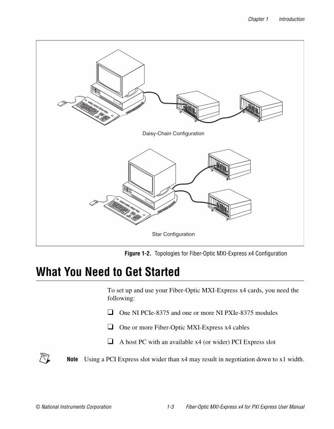
Larger Fiber-Optic MXI-Express x4 SystemsIt is possible to control more than one PXI Express chassis with a single PC. There are two possible topologies: star topology or daisy-chain topology.
The star topology requires the host PC to have a PCI Express x4 slot available for each PXI Express chassis you want to control. Each PXI Express chassis is connected directly to an NI PCIe-8375 installed in the host computer. This topology has the highest throughput; however, it requires one PCI Express x4 slot and one NI PCIe-8375 for each PXI Express chassis. Figure 1-2 shows an example of a star topology.
The NI PXIe-8375 has two Fiber-Optic ports on its front panel: an upstream port (for connecting towards the host) and a downstream port (which allows for daisy chaining). In the daisy-chain configuration, only a single PCI Express x4 slot is required in the host, but the data throughput might be lower, especially for devices further down the chain. Figure 1-2 also shows an example of a daisy chain configuration.
PC to PXI Express/CompactPCI Express
Chapter 1 Introduction
© National Instruments Corporation 1-3 Fiber-Optic MXI-Express x4 for PXI Express User Manual
Figure 1-2. Topologies for Fiber-Optic MXI-Express x4 Configuration
What You Need to Get StartedTo set up and use your Fiber-Optic MXI-Express x4 cards, you need the following:
❑ One NI PCIe-8375 and one or more NI PXIe-8375 modules
❑ One or more Fiber-Optic MXI-Express x4 cables
❑ A host PC with an available x4 (or wider) PCI Express slot
Note Using a PCI Express slot wider than x4 may result in negotiation down to x1 width.
Daisy-Chain Configuration
Star Configuration
Chapter 1 Introduction
Fiber-Optic MXI-Express x4 for PXI Express User Manual 1-4 ni.com
Note The NI PCIe-8375 requires a host computer that supplies a PCI Express clock that adheres to the PCI Express Specification. The NI PCIe-8375 may not be compatible with systems with noncompliant clocks, particularly systems with clocks whose frequency peaks over 100 MHz. Refer to the NI PCIe-8375 web page on ni.com for more information.
❑ An expansion chassis—the PXI Express or CompactPCI Express chassis that you control with Fiber-Optic MXI-Express x4
Note Your PXI Express Fiber-Optic MXI-Express x4 card will work in any standard CompactPCI Express chassis adhering to the PICMG CompactPCI Express EXP.0 R1.0 Specification, or in a PXI Express chassis compatible with the PXI Express Hardware Specification, Revision 1.0 or later. Your PCI Express Fiber-Optic MXI-Express x4 card will work in systems compliant with the PCI Express Specification, Revision 1.0a or later.
UnpackingYour Fiber-Optic MXI-Express x4 cards are shipped in antistatic packages to prevent electrostatic damage (ESD) to the devices. ESD can damage several components on the device.
Caution Never touch the exposed pins of connectors. Doing so may damage the device.
To avoid such damage in handling the device, take the following precautions:
• Ground yourself using a grounding strap or by holding a grounded object.
• Touch the antistatic package to a metal part of the computer chassis before removing the device from the package.
Remove the device from the package and inspect the device for loose components or any sign of damage. Notify NI if the device appears damaged in any way. Do not install a damaged device into the computer or into a PXI Express or CompactPCI Express chassis.
Store the device in the antistatic envelope when not in use.
© National Instruments Corporation 2-1 Fiber-Optic MXI-Express x4 for PXI Express User Manual
2Hardware Installation
This chapter explains how to install the Fiber-Optic MXI-Express x4 hardware.
Hardware InstallationThe following are general instructions for installing the Fiber-Optic MXI-Express x4 cards. Consult your computer user manual or technical reference manual for specific instructions and warnings.
Note The PXI Platform Services software on the PXI Platform Services CD or driver CD included with your PXI Express Fiber-Optic MXI-Express x4 hardware is required to provide chassis and controller identification for PXI features such as trigger routing and slot detection. The PXI Platform Services software is also included with the NI-DAQmx and NI-VISA drivers. For more information, refer to KnowledgeBase 3TJDOND8 at ni.com.
Installing an NI PCIe-8375Complete the following steps to install the NI PCIe-8375 in your computer.
1. Power down the computer and remove the top cover to have access to the PCI Express expansion slots.
2. Touch the metal part of the power supply case inside the computer to discharge any static electricity that might be on your clothes or body. Adhere to proper ESD precautions described in the Unpacking section of Chapter 1, Introduction.
3. Unplug the computer.
Caution To protect both yourself and the computer from electrical hazards, your computer should remain off until you finish installing the NI PCIe-8375.
4. Select any available PCI Express expansion slot (x4 or wider).
Note Using a PCI Express slot wider than x4 may result in negotiation down to x1 width.
Chapter 2 Hardware Installation
Fiber-Optic MXI-Express x4 for PXI Express User Manual 2-2 ni.com
Note The BIOS or motherboard may not support the NI PCIe-8375 in a slot intended for a graphics card.
Note The NI PCIe-8375 requires a host computer that supplies a PCI Express clock that adheres to the PCI Express Specification. The NI PCIe-8375 may not be compatible with systems with noncompliant clocks, particularly systems with clocks whose frequency peaks over 100 MHz. Refer to the NI PCIe-8375 web page on ni.com for more information.
5. Locate the metal bracket that covers the cut-out in the back panel of the computer for the slot you have selected. Remove and save the bracket-retaining screw and the bracket cover.
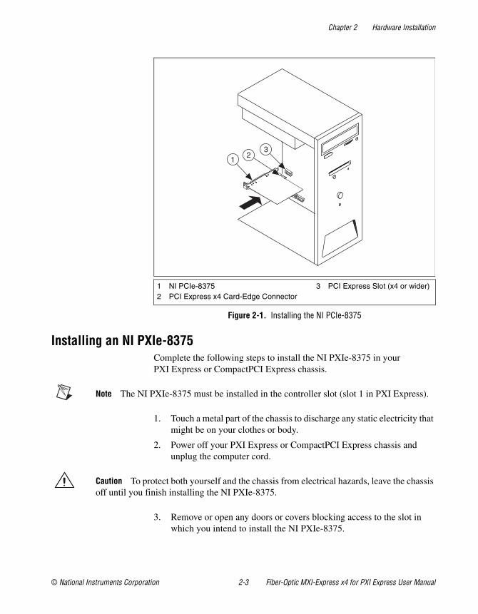
6. Line up the NI PCIe-8375 with the slot on the back panel. Slowly lower the NI PCIe-8375 until its card-edge connector is resting on the expansion slot receptacle. Using slow, evenly distributed pressure, press the NI PCIe-8375 straight down until it seats in the expansion slot, as shown in Figure 2-1.
7. Reinstall the bracket-retaining screw to secure the NI PCIe-8375 to the back panel rail.
8. Replace the computer cover.
Chapter 2 Hardware Installation
© National Instruments Corporation 2-3 Fiber-Optic MXI-Express x4 for PXI Express User Manual
Figure 2-1. Installing the NI PCIe-8375
Installing an NI PXIe-8375Complete the following steps to install the NI PXIe-8375 in your PXI Express or CompactPCI Express chassis.
Note The NI PXIe-8375 must be installed in the controller slot (slot 1 in PXI Express).
1. Touch a metal part of the chassis to discharge any static electricity that might be on your clothes or body.
2. Power off your PXI Express or CompactPCI Express chassis and unplug the computer cord.
Caution To protect both yourself and the chassis from electrical hazards, leave the chassis off until you finish installing the NI PXIe-8375.
3. Remove or open any doors or covers blocking access to the slot in which you intend to install the NI PXIe-8375.
1 NI PCIe-83752 PCI Express x4 Card-Edge Connector
3 PCI Express Slot (x4 or wider)
13
2
Chapter 2 Hardware Installation
Fiber-Optic MXI-Express x4 for PXI Express User Manual 2-4 ni.com
4. Make sure the injector/ejector handle is in its downward position. Be sure to remove all connector packaging and protective caps from retaining screws on the module. Align the NI PXIe-8375 with the card guides on the top and bottom of the system controller slot.
Caution Do not raise the injector/ejector handle as you insert the NI PXIe-8375. It will not insert properly unless the handle is in its downward position so that it does not interfere with the injector/ejector rail on the chassis, as shown in Figure 2-2.
5. Hold the handle as you slowly slide the module into the chassis until the handle catches on the injector/ejector rail.
6. Raise the injector/ejector handle until the module firmly seats into the backplane receptacle connectors. The front panel of the NI PXIe-8375 should be even with the front panel of the chassis.
Note LEDs on the back side of the NI PXIe-8375 card will light, indicating the presence of 5V auxiliary power.
7. Tighten the bracket-retaining screws on the top and bottom of the front panel to secure the NI PXIe-8375 to the chassis.
8. Replace or close any doors or covers to the chassis.
Chapter 2 Hardware Installation
© National Instruments Corporation 2-5 Fiber-Optic MXI-Express x4 for PXI Express User Manual
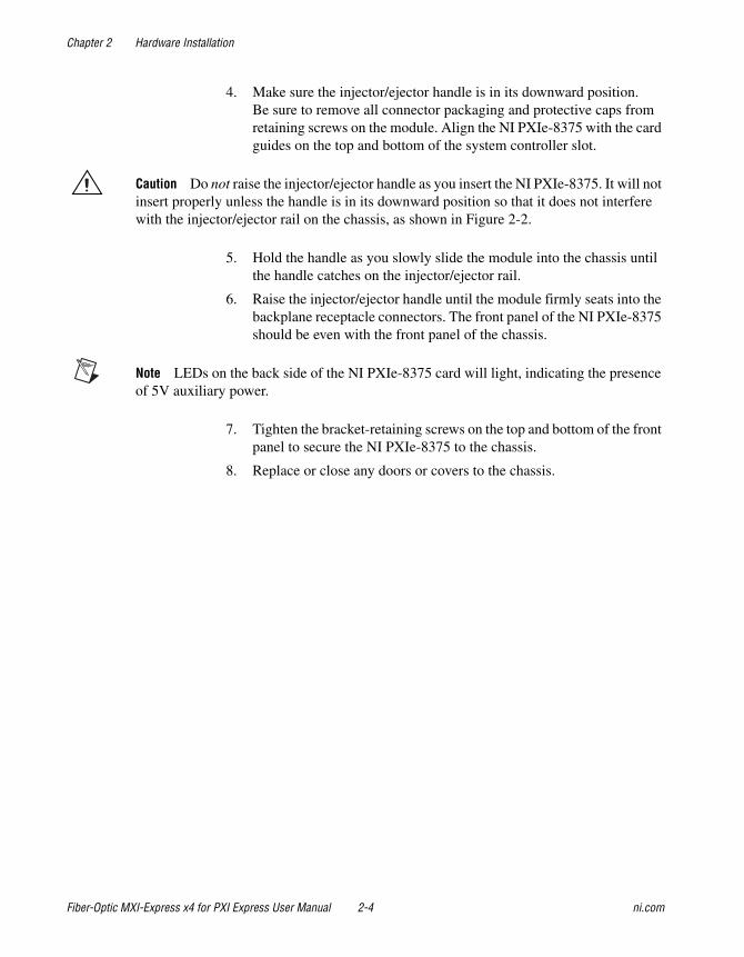
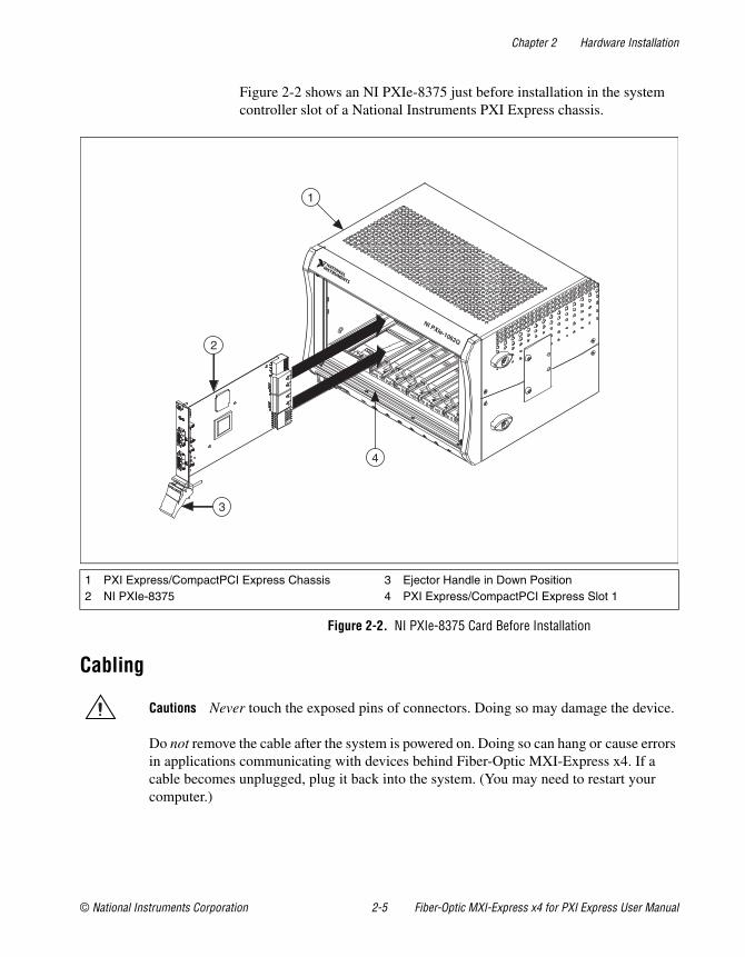
Figure 2-2 shows an NI PXIe-8375 just before installation in the system controller slot of a National Instruments PXI Express chassis.
Figure 2-2. NI PXIe-8375 Card Before Installation
Cabling
Cautions Never touch the exposed pins of connectors. Doing so may damage the device.
Do not remove the cable after the system is powered on. Doing so can hang or cause errors in applications communicating with devices behind Fiber-Optic MXI-Express x4. If a cable becomes unplugged, plug it back into the system. (You may need to restart your computer.)
1 PXI Express/CompactPCI Express Chassis2 NI PXIe-8375
3 Ejector Handle in Down Position4 PXI Express/CompactPCI Express Slot 1
2
3
1
4
NI PXIe-1062Q
Chapter 2 Hardware Installation
Fiber-Optic MXI-Express x4 for PXI Express User Manual 2-6 ni.com
Notes The cables are shipped with a protective plastic cap which must be removed before connecting the cable to the Fiber-Optic MXI-Express x4 hardware. The protective cap should be used when the cable is stored.
For more information about cables, refer to the Cable Options section of Chapter 3, Hardware Overview.
If daisy chaining additional chassis, connect PORT 2 of the NI PXIe-8375 closer to the system controller to PORT 1 of the NI PXIe-8375 of the daisy chained chassis.
Connect the Fiber-Optic MXI-Express x4 cable to the NI PCIe-8375 and to PORT 1 of the NI PXIe-8375. The cables have no polarity, so either end may be connected to either card.
Powering Up the Fiber-Optic MXI-Express x4 System1. Power-on all of the expansion chassis in any order you choose.
2. Power-on the host.
Standard PCI-PCI bridges and switches are used to add PCI devices to a PCI hierarchy in which all the bridges and devices are contained within a single chassis. Because of this, BIOSes and operating systems make the assumption that all PCI devices in the entire hierarchy will be available as soon as code execution begins at power-up. This assumption means that all of the expansion chassis must be turned on before the host PC for the BIOS and OS to correctly configure a Fiber-Optic MXI-Express x4 system.
Note There are no requirements on how Fiber-Optic MXI-Express x4 expansion chassis are powered up relative to each other, as long as they are all on before the computer is powered on.
Powering Down the Fiber-Optic MXI-Express x4 SystemBecause operating systems and drivers commonly make the assumption that PCI devices will be present in the system from power-up to power-down, it is important not to power off the expansion chassis until after the host PC is powered off. Powering off the expansion chassis while the host is still on can cause crashes or hangs.
After the host computer has powered down, the order in which expansion chassis are powered off relative to each other is not important. However, to power down a chassis that still has its upstream link active, the power button must be pressed for at least 4 seconds.
© National Instruments Corporation 3-1 Fiber-Optic MXI-Express x4 for PXI Express User Manual
3Hardware Overview
This chapter presents an overview of Fiber-Optic MXI-Express x4 hardware functionality and explains the operation of each functional unit.
Functional OverviewFiber-Optic MXI-Express x4 is based on PCI Express technology. A Fiber-Optic MXI-Express x4 kit uses PCI Express switches to enable control of a PXI Express or CompactPCI Express chassis from a PC with an available PCI Express slot. The PCI Express switch architecture is transparent to device drivers, so no additional software is needed to support using PXI Express and CompactPCI Express devices in a chassis connected using Fiber-Optic MXI-Express x4.
Note The PXI Platform Services software on the PXI Platform Services CD or driver CD included with your PXI Express Fiber-Optic MXI-Express x4 hardware is required to provide chassis and controller identification for PXI features such as trigger routing and slot detection. The PXI Platform Services software is also included with the NI-DAQmx and NI-VISA drivers. For more information, refer to KnowledgeBase 3TJDOND8 at ni.com.
The link between the PC and the chassis is a x4 PCI Express link. This link is a dual-simplex communication channel comprised of low-voltage, differentially driven signal pairs. The link can transmit at a rate of 10 Gbps in each direction simultaneously, though protocol overhead and other inefficiencies will reduce the achievable throughput.
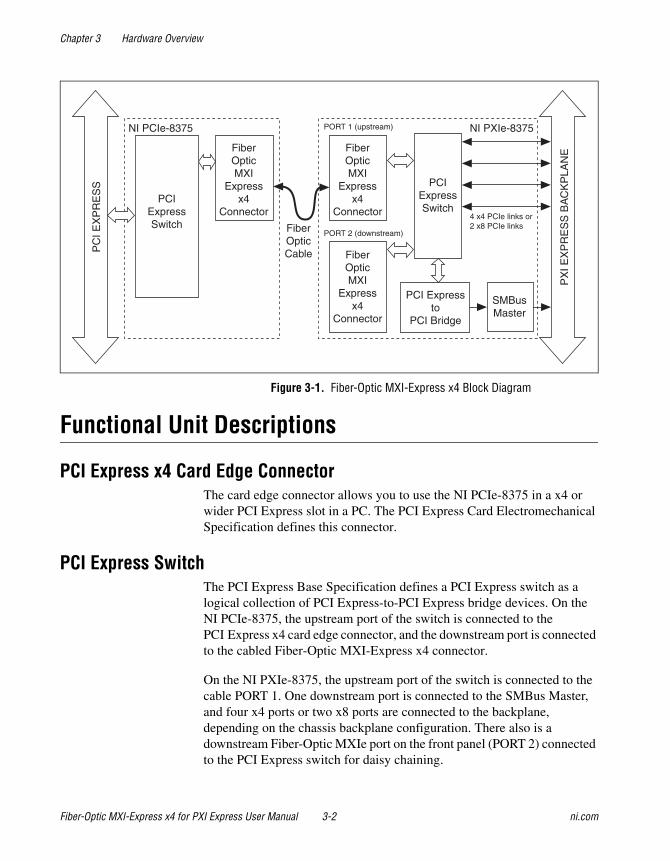
Figure 3-1 shows the basic architecture of Fiber-Optic MXI-Express x4. The NI PCIe-8375 consists of a PCI Express x4 card edge connector, a PCI Express switch, and one cabled Fiber-Optic MXI-Express x4 connector. The NI PXIe-8375 consists of two cabled Fiber-Optic MXI-Express x4 connectors, a PCI Express switch, and two PXI Express connectors.
Chapter 3 Hardware Overview
Fiber-Optic MXI-Express x4 for PXI Express User Manual 3-2 ni.com
Figure 3-1. Fiber-Optic MXI-Express x4 Block Diagram
Functional Unit Descriptions
PCI Express x4 Card Edge ConnectorThe card edge connector allows you to use the NI PCIe-8375 in a x4 or wider PCI Express slot in a PC. The PCI Express Card Electromechanical Specification defines this connector.
PCI Express SwitchThe PCI Express Base Specification defines a PCI Express switch as a logical collection of PCI Express-to-PCI Express bridge devices. On the NI PCIe-8375, the upstream port of the switch is connected to the PCI Express x4 card edge connector, and the downstream port is connected to the cabled Fiber-Optic MXI-Express x4 connector.
On the NI PXIe-8375, the upstream port of the switch is connected to the cable PORT 1. One downstream port is connected to the SMBus Master, and four x4 ports or two x8 ports are connected to the backplane, depending on the chassis backplane configuration. There also is a downstream Fiber-Optic MXIe port on the front panel (PORT 2) connected to the PCI Express switch for daisy chaining.
NI PCIe-8375
PCIExpressSwitch
NI PXIe-8375
SMBusMaster
PCI Expressto
PCI Bridge
PC
I EX
PR
ES
S
PX
I EX
PR
ES
S B
AC
KP
LAN
E
PCIExpressSwitch
4 x4 PCIe links or2 x8 PCIe links
FiberOpticMXI
Expressx4
Connector
FiberOpticMXI
Expressx4
Connector
FiberOpticCable
PORT 1 (upstream)
PORT 2 (downstream)
FiberOpticMXI
Expressx4
Connector
Chapter 3 Hardware Overview
© National Instruments Corporation 3-3 Fiber-Optic MXI-Express x4 for PXI Express User Manual
Cabled Fiber-Optic MXI-Express x4 ConnectorThe cabled Fiber-Optic MXI-Express x4 connector provides the transmit and receive signals to connect an NI PCIe-8375 and an NI PXIe-8375.
PCI Express-to-PCI BridgeThe PCI Express Base Specification defines a PCI Express-to-PCI bridge as a device that connects a PCI Express fabric and a PCI hierarchy. On the NI PXIe-8375, the PCI Express-to-PCI bridge connects the PCI Express switch and an SMBus Master on the card.
SMBus MasterThe SMBus is a low-speed bus for reading and configuring devices outside the normal PCI Express mechanism. The PXI Express specification requires controllers to supply an SMBus for reading chassis configuration information from an EPROM. It may also be used for fan control, power monitors, or other system devices. In addition, devices on plug-in boards may connect to the SMBus for purposes specific to those devices.
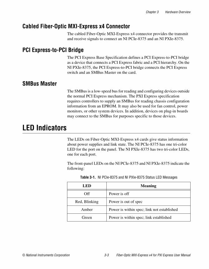
LED IndicatorsThe LEDs on Fiber-Optic MXI-Express x4 cards give status information about power supplies and link state. The NI PCIe-8375 has one tri-color LED for the port on the panel. The NI PXIe-8375 has two tri-color LEDs, one for each port.
The front-panel LEDs on the NI PCIe-8375 and NI PXIe-8375 indicate the following:
Table 3-1. NI PCIe-8375 and NI PXIe-8375 Status LED Messages
LED Meaning
Off Power is off
Red, Blinking Power is out of spec
Amber Power is within spec; link not established
Green Power is within spec; link established
Chapter 3 Hardware Overview
Fiber-Optic MXI-Express x4 for PXI Express User Manual 3-4 ni.com
The NI PXIe-8375 has some additional LEDs on the back side of the board near the front-panel connector. These LEDs give additional information about the link status of the PCI Express lanes on the module to the backplane. For more information, refer to KnowledgeBase 3U7CDCD8 at ni.com.
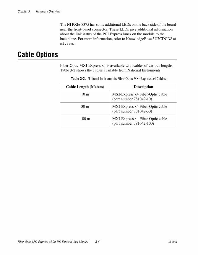
Cable OptionsFiber-Optic MXI-Express x4 is available with cables of various lengths. Table 3-2 shows the cables available from National Instruments.
Table 3-2. National Instruments Fiber-Optic MXI-Express x4 Cables
Cable Length (Meters) Description
10 m MXI-Express x4 Fiber-Optic cable (part number 781042-10)
30 m MXI-Express x4 Fiber-Optic cable (part number 781042-30)
100 m MXI-Express x4 Fiber-Optic cable (part number 781042-100)
© National Instruments Corporation A-1 Fiber-Optic MXI-Express x4 for PXI Express User Manual
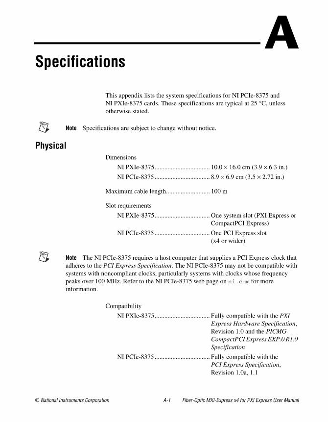
ASpecifications
This appendix lists the system specifications for NI PCIe-8375 and NI PXIe-8375 cards. These specifications are typical at 25 °C, unless otherwise stated.
Note Specifications are subject to change without notice.
PhysicalDimensions
NI PXIe-8375.................................. 10.0 × 16.0 cm (3.9 × 6.3 in.)
NI PCIe-8375.................................. 8.9 × 6.9 cm (3.5 × 2.72 in.)
Maximum cable length........................... 100 m
Slot requirements
NI PXIe-8375.................................. One system slot (PXI Express or CompactPCI Express)
NI PCIe-8375.................................. One PCI Express slot(x4 or wider)
Note The NI PCIe-8375 requires a host computer that supplies a PCI Express clock that adheres to the PCI Express Specification. The NI PCIe-8375 may not be compatible with systems with noncompliant clocks, particularly systems with clocks whose frequency peaks over 100 MHz. Refer to the NI PCIe-8375 web page on ni.com for more information.
Compatibility
NI PXIe-8375.................................. Fully compatible with the PXI Express Hardware Specification, Revision 1.0 and the PICMG CompactPCI Express EXP.0 R1.0 Specification
NI PCIe-8375.................................. Fully compatible with the PCI Express Specification, Revision 1.0a, 1.1
Appendix A Specifications
Fiber-Optic MXI-Express x4 for PXI Express User Manual A-2 ni.com
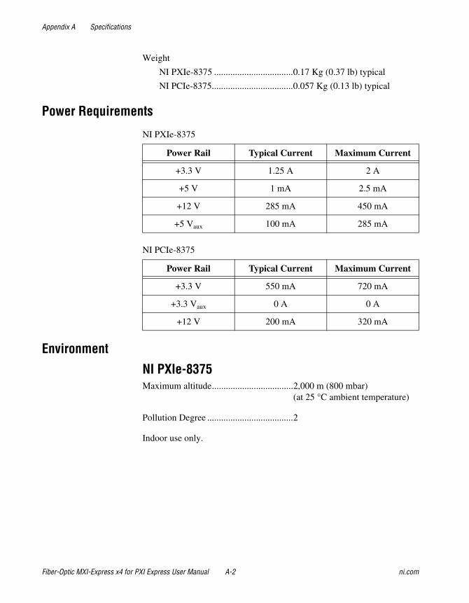
Weight
NI PXIe-8375 ..................................0.17 Kg (0.37 lb) typical
NI PCIe-8375...................................0.057 Kg (0.13 lb) typical
Power Requirements
NI PXIe-8375
NI PCIe-8375
Environment
NI PXIe-8375Maximum altitude...................................2,000 m (800 mbar)
(at 25 °C ambient temperature)
Pollution Degree .....................................2
Indoor use only.
Power Rail Typical Current Maximum Current
+3.3 V 1.25 A 2 A
+5 V 1 mA 2.5 mA
+12 V 285 mA 450 mA
+5 Vaux 100 mA 285 mA
Power Rail Typical Current Maximum Current
+3.3 V 550 mA 720 mA
+3.3 Vaux 0 A 0 A
+12 V 200 mA 320 mA
Appendix A Specifications
© National Instruments Corporation A-3 Fiber-Optic MXI-Express x4 for PXI Express User Manual
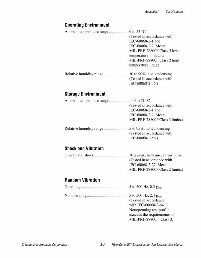
Operating EnvironmentAmbient temperature range.................... 0 to 55 °C
(Tested in accordance with IEC-60068-2-1 and IEC-60068-2-2. Meets MIL-PRF-28800F Class 3 low temperature limit and MIL-PRF-28800F Class 2 high temperature limit.)
Relative humidity range ......................... 10 to 90%, noncondensing (Tested in accordance with IEC-60068-2-56.)
Storage EnvironmentAmbient temperature range.................... –40 to 71 °C
(Tested in accordance with IEC-60068-2-1 and IEC-60068-2-2. Meets MIL-PRF-28800F Class 3 limits.)
Relative humidity range ......................... 5 to 95%, noncondensing (Tested in accordance with IEC-60068-2-56.)
Shock and VibrationOperational shock .................................. 30 g peak, half-sine, 11 ms pulse
(Tested in accordance with IEC-60068-2-27. Meets MIL-PRF-28800F Class 2 limits.)
Random VibrationOperating................................................ 5 to 500 Hz, 0.3 grms
Nonoperating.......................................... 5 to 500 Hz, 2.4 grms
(Tested in accordance with IEC-60068-2-64. Nonoperating test profile exceeds the requirements of MIL-PRF-28800F, Class 3.)
Appendix A Specifications
Fiber-Optic MXI-Express x4 for PXI Express User Manual A-4 ni.com
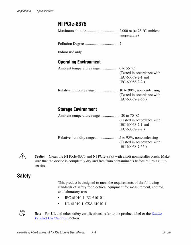
NI PCIe-8375Maximum altitude...................................2,000 m (at 25 °C ambient
temperature)
Pollution Degree .....................................2
Indoor use only
Operating EnvironmentAmbient temperature range ....................0 to 55 °C
(Tested in accordance with IEC-60068-2-1 and IEC-60068-2-2.)
Relative humidity range..........................10 to 90%, noncondensing (Tested in accordance with IEC-60068-2-56.)
Storage EnvironmentAmbient temperature range ....................–20 to 70 °C
(Tested in accordance with IEC-60068-2-1 and IEC-60068-2-2.)
Relative humidity range..........................5 to 95%, noncondensing (Tested in accordance with IEC-60068-2-56.)
Caution Clean the NI PXIe-8375 and NI PCIe-8375 with a soft nonmetallic brush. Make sure that the device is completely dry and free from contaminants before returning it to service.
SafetyThis product is designed to meet the requirements of the following standards of safety for electrical equipment for measurement, control, and laboratory use:
• IEC 61010-1, EN 61010-1
• UL 61010-1, CSA 61010-1
Note For UL and other safety certifications, refer to the product label or the Online Product Certification section.
Appendix A Specifications
© National Instruments Corporation A-5 Fiber-Optic MXI-Express x4 for PXI Express User Manual
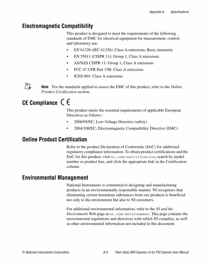
Electromagnetic CompatibilityThis product is designed to meet the requirements of the following standards of EMC for electrical equipment for measurement, control, and laboratory use:
• EN 61326 (IEC 61326): Class A emissions; Basic immunity
• EN 55011 (CISPR 11): Group 1, Class A emissions
• AS/NZS CISPR 11: Group 1, Class A emissions
• FCC 47 CFR Part 15B: Class A emissions
• ICES-001: Class A emissions
Note For the standards applied to assess the EMC of this product, refer to the Online Product Certification section.
CE ComplianceThis product meets the essential requirements of applicable European Directives as follows:
• 2006/95/EC; Low-Voltage Directive (safety)
• 2004/108/EC; Electromagnetic Compatibility Directive (EMC)
Online Product CertificationRefer to the product Declaration of Conformity (DoC) for additional regulatory compliance information. To obtain product certifications and the DoC for this product, visit ni.com/certification, search by model number or product line, and click the appropriate link in the Certification column.
Environmental ManagementNational Instruments is committed to designing and manufacturing products in an environmentally responsible manner. NI recognizes that eliminating certain hazardous substances from our products is beneficial not only to the environment but also to NI customers.
For additional environmental information, refer to the NI and the Environment Web page at ni.com/environment. This page contains the environmental regulations and directives with which NI complies, as well as other environmental information not included in this document.

Appendix A Specifications
Fiber-Optic MXI-Express x4 for PXI Express User Manual A-6 ni.com
Waste Electrical and Electronic Equipment (WEEE) EU Customers At the end of the product life cycle, all products must be sent to a WEEE recycling center. For more information about WEEE recycling centers, National Instruments WEEE initiatives, and compliance with WEEE Directive 2002/96/EC on Waste Electrical and Electronic Equipment, visit ni.com/environment/weee.
RoHSNational Instruments (RoHS)
National Instruments RoHS ni.com/environment/rohs_china(For information about China RoHS compliance, go to ni.com/environment/rohs_china.)
© National Instruments Corporation B-1 Fiber-Optic MXI-Express x4 for PXI Express User Manual
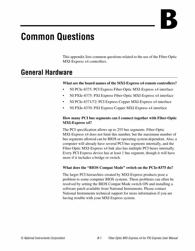
BCommon Questions
This appendix lists common questions related to the use of the Fiber-Optic MXI-Express x4 controllers.
General HardwareWhat are the board names of the MXI-Express x4 remote controllers?
• NI PCIe-8375: PCI Express Fiber-Optic MXI-Express x4 interface
• NI PXIe-8375: PXI Express Fiber-Optic MXI-Express x4 interface
• NI PCIe-8371/72: PCI Express Copper MXI-Express x4 interface
• NI PXIe-8370: PXI Express Copper MXI-Express x4 interface
How many PCI bus segments can I connect together with Fiber-Optic MXI-Express x4?
The PCI specification allows up to 255 bus segments. Fiber-Optic MXI-Express x4 does not limit this number, but the maximum number of bus segments allowed can be BIOS or operating system dependent. Also, a computer will already have several PCI bus segments internally, and the Fiber-Optic MXI-Express x4 link also has multiple PCI buses internally. Every PCI Express device has at least 1 bus segment, though it will have more if it includes a bridge or switch.
What does the “BIOS Compat Mode” switch on the PCIe-8375 do?
The larger PCI hierarchies created by MXI-Express products pose a problem to some computer BIOS systems. These problems can often be resolved by setting the BIOS Compat Mode switch ON and installing a software patch available from National Instruments. Please contact National Instruments technical support for more information if you are having trouble with your MXI Express system.
Appendix B Common Questions
Fiber-Optic MXI-Express x4 for PXI Express User Manual B-2 ni.com
General CablingWhat is the maximum length of a Fiber-Optic MXI-Express x4 Fiber-Optic cable?
The maximum length for a Fiber-Optic MXI-Express x4 Fiber-Optic cable is 100 m. National Instruments offers 10 m, 30 m, and 100 m Fiber-Optic cables.
General SoftwareUnder which operating systems will Fiber-Optic MXI-Express x4 work?
Fiber-Optic MXI-Express x4 will be recognized as a collection of PCI-to-PCI bridges to the majority of operating systems. It should automatically work with most systems like Windows, Macintosh OS X, Linux, and Solaris, but only Windows Vista/XP has been verified in the initial release of Fiber-Optic MXI-Express x4.
What software is required to use my Fiber-Optic MXI-Express x4 kit?
For Windows and LabVIEW RT, the required software is included as part of the latest version of NI PXI Platform Services included with your kit. The software for your Fiber-Optic MXI-Express x4 controller enhances the product, allowing you to view information about the organization of your PXI system and programmatically retrieve data about the chassis and modules you have installed.
If the Fiber-Optic MXI-Express x4 software does not support your operating system, you can still use Fiber-Optic MXI-Express x4 and the operating system will provide a mechanism for you to ignore the SMBus master that is built into the Fiber-Optic MXI-Express x4 hardware.
How does my Fiber-Optic MXI-Express x4 board show up in the Windows Device Manager?
Fiber-Optic MXI-Express x4 boards contain two types of PCI devices onboard and will have several listings in the Windows Device Manager (WDM). The first devices show up in the WDM listed under System devices as PCI standard PCI-to-PCI bridges. The second device type shows up in the WDM as a National Instruments SMBus Controller when the correct MXI-Express x4 driver is installed. This second device provides configuration information about the chassis. The NI PCIe-8375
Appendix B Common Questions
© National Instruments Corporation B-3 Fiber-Optic MXI-Express x4 for PXI Express User Manual
includes two PCI standard PCI-to-PCI bridges. The NI PXIe-8375 includes five to seven bridges and one NI PXIe-8375 SMBus Controller device.
If the Fiber-Optic MXI-Express x4 software is not installed, the PCI-to-PCI function will still be detected and work correctly, but the SMBus master will be detected as an unknown device.
MXI-4 to Fiber-Optic MXI-Express x4 Upgrade QuestionsWhat are some of the improvements from MXI-4 to Fiber-Optic MXI-Express x4?
Fiber-Optic MXI-Express x4 incorporates the latest technology to include:
• Support for PCI Express slots.
• Support for PXI Express and CompactPCI Express chassis.
• Improved error correction and handling for noisy or harsh environments.
• Improved mechanical connectivity.
• Improved performance (higher throughput).
Can a MXI-4 and Fiber-Optic MXI-Express x4 board be used together directly?
No. MXI-4 and Fiber-Optic MXI-Express x4 boards use different cable connectors and cannot be connected together. Additionally, the board-to-board communication protocols differ.
Can I use a MXI-4 and Fiber-Optic MXI-Express x4 kit in the same multichassis PXI system?
Yes. Different MXI kits can be intermixed to connect multiple PXI and PXI Express chassis together. As mentioned previously, an individual MXI-4 board will not cable directly to a Fiber-Optic MXI-Express x4 board.
MXI-4 systems required the use of a specific boot ordering. Is this a requirement with Fiber-Optic MXI-Express x4?
Yes. The requirements of the PCI bus still mandate that you must power-on secondary PXI/PXI Express chassis before powering on the host PC when using Fiber-Optic MXI-Express x4.
© National Instruments Corporation C-1 Fiber-Optic MXI-Express x4 for PXI Express User Manual
CTechnical Support and Professional Services
Visit the following sections of the award-winning National Instruments Web site at ni.com for technical support and professional services:
• Support—Technical support at ni.com/support includes the following resources:
– Self-Help Technical Resources—For answers and solutions, visit ni.com/support for software drivers and updates, a searchable KnowledgeBase, product manuals, step-by-step troubleshooting wizards, thousands of example programs, tutorials, application notes, instrument drivers, and so on. Registered users also receive access to the NI Discussion Forums at ni.com/forums. NI Applications Engineers make sure every question submitted online receives an answer.
– Standard Service Program Membership—This program entitles members to direct access to NI Applications Engineers via phone and email for one-to-one technical support as well as exclusive access to on demand training modules via the Services Resource Center. NI offers complementary membership for a full year after purchase, after which you may renew to continue your benefits.
For information about other technical support options in your area, visit ni.com/services, or contact your local office at ni.com/contact.
• Training and Certification—Visit ni.com/training for self-paced training, eLearning virtual classrooms, interactive CDs, and Certification program information. You also can register for instructor-led, hands-on courses at locations around the world.
• System Integration—If you have time constraints, limited in-house technical resources, or other project challenges, National Instruments Alliance Partner members can help. To learn more, call your local NI office or visit ni.com/alliance.
Appendix C Technical Support and Professional Services
© National Instruments Corporation C-2 Fiber-Optic MXI-Express x4 for PXI Express User Manual
• Declaration of Conformity (DoC)—A DoC is our claim of compliance with the Council of the European Communities using the manufacturer’s declaration of conformity. This system affords the user protection for electromagnetic compatibility (EMC) and product safety. You can obtain the DoC for your product by visiting ni.com/certification.
• Calibration Certificate—If your product supports calibration, you can obtain the calibration certificate for your product at ni.com/calibration.
If you searched ni.com and could not find the answers you need, contact your local office or NI corporate headquarters. Phone numbers for our worldwide offices are listed at the front of this manual. You also can visit the Worldwide Offices section of ni.com/niglobal to access the branch office Web sites, which provide up-to-date contact information, support phone numbers, email addresses, and current events.
© National Instruments Corporation G-1 Fiber-Optic MXI-Express x4 for PXI Express User Manual
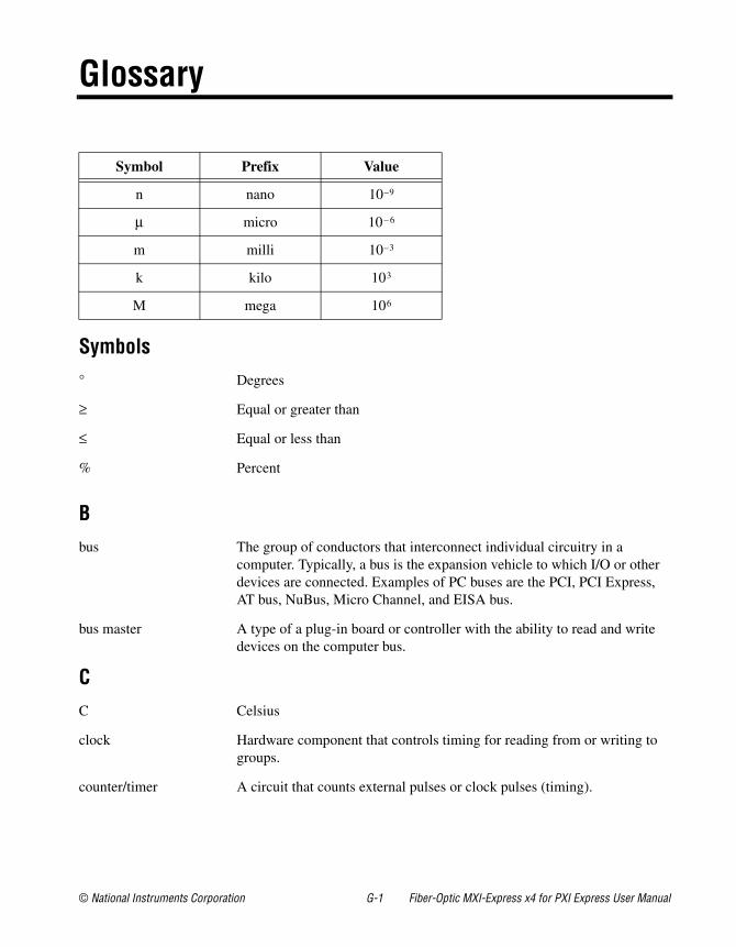
Glossary
Symbol Prefix Value
n nano 10–9
μ micro 10– 6
m milli 10–3
k kilo 103
M mega 106
Symbols° Degrees
≥ Equal or greater than
≤ Equal or less than
% Percent
Bbus The group of conductors that interconnect individual circuitry in a
computer. Typically, a bus is the expansion vehicle to which I/O or other devices are connected. Examples of PC buses are the PCI, PCI Express, AT bus, NuBus, Micro Channel, and EISA bus.
bus master A type of a plug-in board or controller with the ability to read and write devices on the computer bus.
CC Celsius
clock Hardware component that controls timing for reading from or writing to groups.
counter/timer A circuit that counts external pulses or clock pulses (timing).
Glossary
© National Instruments Corporation G-2 Fiber-Optic MXI-Express x4 for PXI Express User Manual
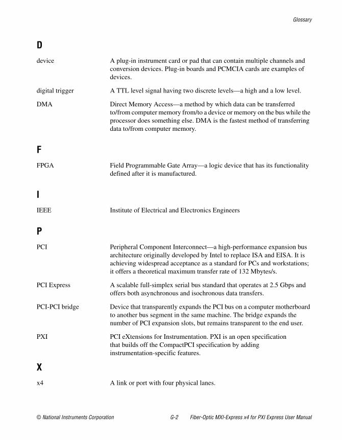
Ddevice A plug-in instrument card or pad that can contain multiple channels and
conversion devices. Plug-in boards and PCMCIA cards are examples of devices.
digital trigger A TTL level signal having two discrete levels—a high and a low level.
DMA Direct Memory Access—a method by which data can be transferred to/from computer memory from/to a device or memory on the bus while the processor does something else. DMA is the fastest method of transferring data to/from computer memory.
FFPGA Field Programmable Gate Array—a logic device that has its functionality
defined after it is manufactured.
IIEEE Institute of Electrical and Electronics Engineers
PPCI Peripheral Component Interconnect—a high-performance expansion bus
architecture originally developed by Intel to replace ISA and EISA. It is achieving widespread acceptance as a standard for PCs and workstations; it offers a theoretical maximum transfer rate of 132 Mbytes/s.
PCI Express A scalable full-simplex serial bus standard that operates at 2.5 Gbps and offers both asynchronous and isochronous data transfers.
PCI-PCI bridge Device that transparently expands the PCI bus on a computer motherboard to another bus segment in the same machine. The bridge expands the number of PCI expansion slots, but remains transparent to the end user.
PXI PCI eXtensions for Instrumentation. PXI is an open specification that builds off the CompactPCI specification by adding instrumentation-specific features.
Xx4 A link or port with four physical lanes.
© National Instruments Corporation I-1 Fiber-Optic MXI-Express x4 for PXI Express User Manual
Index
Aadditional Fiber-Optic MXI-Express x4
configuration (figure), 1-3
Bbasic Fiber-Optic MXI-Express x4
configuration (figure), 1-2system, 1-2
block diagram (figure), 3-2
Ccable options (table), 3-4cabled Fiber-Optic MXI-Express x4
connector, 3-3cabling common questions, B-2calibration certificate (NI resources), C-2card edge connector, 3-2CE compliance, specifications, A-5cleaning, A-4common questions
general cabling, B-2general hardware, B-1general software, B-2MXI-4 to Fiber-Optic MXI-Express x4, B-3
configurationadditional topologies (figure), 1-3basic (figure), 1-2
conventions used in the manual, vii
DDeclaration of Conformity (NI resources), C-2diagnostic tools (NI resources), C-1documentation
conventions used in manual, viiNI resources, C-1related documentation, viii
drivers (NI resources), C-1
Eelectromagnetic compatibility, A-5environmental management, specifications, A-5
WEEE information, A-6environmental specifications, A-2
NI PCIe-8375, A-4NI PXIe-8375, A-2
examples (NI resources), C-1
FFiber-Optic MXI-Express x4
basic system, 1-2block diagram (figure), 3-2hardware overview, 3-1larger systems, 1-2specifications, A-1system
description, 1-1getting started, 1-3
functional unit descriptions, 3-2
Index
© National Instruments Corporation I-2 Fiber-Optic MXI-Express x4 for PXI Express User Manual
Ggetting started, 1-3
Hhardware common questions, B-1help, technical support, C-1
Iinstallation
cabling, 2-5hardware, 2-1of an NI PCIe-8375, 2-1of an NI PXIe-8375, 2-3powering down the Fiber-Optic
MXI-Express x4 system, 2-6powering up the Fiber-Optic
MXI-Express x4 system, 2-6instrument drivers (NI resources), C-1
KKnowledgeBase, C-1
Llarger Fiber-Optic MXI-Express x4
systems, 1-2LED indicators, 3-3
MMXI-4 to Fiber-Optic MXI-Express x4
common questions, B-3MXI-Express x4
cable options (table), 3-4
NNational Instruments support and
services, C-1NI PCIe-8375
installation, 2-1figure, 2-3
NI PXIe-8375installation, 2-3
figure, 2-5
Ooperating environment specifications
NI PCIe-8375, A-4NI PXIe-8375, A-3
overviewfunctional, 3-1functional unit descriptions, 3-2hardware, 3-1
PPCI Express
switch, 3-2to-PCI bridge, 3-3x4 card edge connector, 3-2
physical specifications, A-1, A-2programming examples (NI resources), C-1
Rrandom vibration specifications,
NI PXIe-8375, A-3recycling hardware, A-6related documentation, viii
Index
Fiber-Optic MXI-Express x4 for PXI Express User Manual I-3 ni.com
Ssafety, specifications, A-4shock and vibration specifications
NI PXIe-8375, A-3SMBus Master, 3-3software
common questions, B-2NI resources, C-1
specifications, A-1CE compliance, A-5cleaning, A-4electromagnetic compatibility, A-5environmental, A-2
NI PCIe-8375, A-4NI PXIe-8375, A-2
environmental management, A-5WEEE information, A-6
online product certification, A-5physical, A-1, A-2safety, A-4
storage environment specificationsNI PCIe-8375, A-4NI PXIe-8375, A-3
support, technical, C-1switch, PCI Express, 3-2
Ttechnical support, C-1training and certification (NI resources), C-1troubleshooting (NI resources), C-1
Uunpacking, 1-4
WWeb resources, C-1WEEE information, A-6