Fiber Nonlinearities and Their Impact on Transmission Systems · Tuesday, March 22, 2005 3(32)...
32
Tuesday, March 22, 2005 Electronic Devices Fiber Nonlinearities and Their Fiber Nonlinearities and Their Impact on Transmission Systems Impact on Transmission Systems Stefan Andersson Stefan Andersson [email protected] [email protected] http:// http:// www.ek.isy.liu.se www.ek.isy.liu.se /~stean/ /~stean/
Transcript of Fiber Nonlinearities and Their Impact on Transmission Systems · Tuesday, March 22, 2005 3(32)...

Tuesday, March 22, 2005 Electronic Devices
Fiber Nonlinearities and Their Fiber Nonlinearities and Their Impact on Transmission SystemsImpact on Transmission Systems
Stefan AnderssonStefan [email protected]@isy.liu.se
http://http://www.ek.isy.liu.sewww.ek.isy.liu.se/~stean//~stean/

Tuesday, March 22, 2005
2(32)
OutlineOutlineIntroductionIntroductionAn Overview of Fiber NonlinearitiesAn Overview of Fiber NonlinearitiesStimulated Stimulated BrillouinBrillouin Scattering (SBS)Scattering (SBS)SelfSelf--Phase Modulation (SPM)Phase Modulation (SPM)CrossCross--Phase Modulation (CPM)Phase Modulation (CPM)FourFour--Photon Mixing (FPM)Photon Mixing (FPM)Dispersion ManagementDispersion ManagementModulation Instability (MI)Modulation Instability (MI)Stimulated Raman Scattering (SRS)Stimulated Raman Scattering (SRS)Scaling NonlinearitiesScaling NonlinearitiesSummarySummary
Tuesday, March 22, 2005
3(32)
IntroductionIntroduction
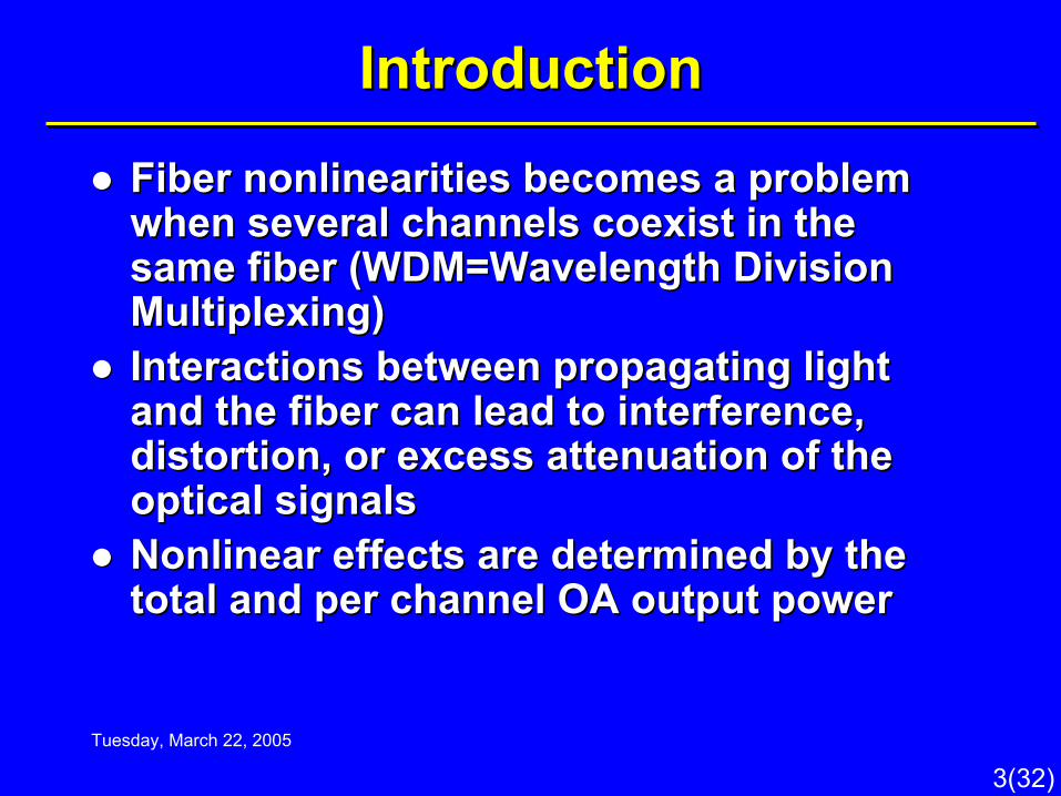
Fiber nonlinearities becomes a problem Fiber nonlinearities becomes a problem when several channels coexist in the when several channels coexist in the same fiber (WDM=Wavelength Division same fiber (WDM=Wavelength Division Multiplexing)Multiplexing)Interactions between propagating light Interactions between propagating light and the fiber can lead to interference, and the fiber can lead to interference, distortion, or excess attenuation of the distortion, or excess attenuation of the optical signalsoptical signalsNonlinear effects are determined by the Nonlinear effects are determined by the total and per channel OA output powertotal and per channel OA output power
Tuesday, March 22, 2005
4(32)
IntroductionIntroduction

Tuesday, March 22, 2005
5(32)
IntroductionIntroduction
Chromatic dispersion: Frequency Chromatic dispersion: Frequency components of modulated signal travel at components of modulated signal travel at different velocities in fiberdifferent velocities in fiber

Tuesday, March 22, 2005
6(32)
An Overview of Fiber NonlinearitiesAn Overview of Fiber Nonlinearities
The nonlinearities in silica fibers can be The nonlinearities in silica fibers can be divided into two categories:divided into two categories:1.1. Stimulated scattering (Stimulated scattering (BrillouinBrillouin and Raman), and Raman),
gives rise to intensity dependent gain or lossgives rise to intensity dependent gain or loss2.2. Effects arising from the nonlinear index of Effects arising from the nonlinear index of
refraction. Gives rise to an intensity dependent refraction. Gives rise to an intensity dependent phase of the optical field leading to distortion, phase of the optical field leading to distortion, cross modulation, etc.cross modulation, etc.

Tuesday, March 22, 2005
7(32)
An Overview of Fiber NonlinearitiesAn Overview of Fiber NonlinearitiesNonlinear interactions between two signals in a Nonlinear interactions between two signals in a fiber can be expressed by the change in the fiber can be expressed by the change in the electric field of one of the signals caused by the electric field of one of the signals caused by the other other
Where Where αα is the loss coefficient, g is the frequencyis the loss coefficient, g is the frequency--dependent gain coefficient of the nonlinear dependent gain coefficient of the nonlinear process, and process, and AAee is the effective area of the fiberis the effective area of the fiberFor more complex situations the nonlinear For more complex situations the nonlinear SchrSchröödinger equation needs to be solveddinger equation needs to be solved
]2/)()2/exp[()()( 211 eAdzzgPdzikzEdzzE ++−=+ α

Tuesday, March 22, 2005
8(32)
An Overview of Fiber NonlinearitiesAn Overview of Fiber Nonlinearities
g is real => gain or loss. Parametric g is real => gain or loss. Parametric interaction between photons and phononsinteraction between photons and phonons–– Stimulated Stimulated BrillouinBrillouin scatteringscattering–– Stimulated Raman scatteringStimulated Raman scattering
g is imaginary => phase modulation. g is imaginary => phase modulation. Modulation of refractive index by light Modulation of refractive index by light intensity fluctuationintensity fluctuation–– Self phase modulation (SPM)Self phase modulation (SPM)–– Cross phase modulation (CPM)Cross phase modulation (CPM)–– FourFour--photon mixing (FPM)photon mixing (FPM)

Tuesday, March 22, 2005
9(32)
Stimulated Stimulated BrillouinBrillouin Scattering (SBS)Scattering (SBS)
SBS is caused by interaction of light with SBS is caused by interaction of light with sound wavessound wavesSound waves in glass cause a variation in Sound waves in glass cause a variation in the index of refractionthe index of refractionA strong wave traveling in one direction A strong wave traveling in one direction provides narrow band gain for light provides narrow band gain for light traveling in the opposite directiontraveling in the opposite directionThe reflected wave experiences a Doppler The reflected wave experiences a Doppler shift of about 20MHz in glassshift of about 20MHz in glass

Tuesday, March 22, 2005
10(32)
Stimulated Stimulated BrillouinBrillouin Scattering (SBS)Scattering (SBS)SBS occurs when the incident light is of SBS occurs when the incident light is of sufficiently high intensity (a few sufficiently high intensity (a few mWmW))The SBS threshold is defined as the input power The SBS threshold is defined as the input power at which the scattered power grows as large as at which the scattered power grows as large as the input powerthe input powerSystem impact:System impact:–– When signal power is transferred in a backward direction it When signal power is transferred in a backward direction it
can deplete the forward traveling signalcan deplete the forward traveling signal–– The transmitted power grows linearly with input power for The transmitted power grows linearly with input power for
low input powers, but saturates for higher input powers (gain low input powers, but saturates for higher input powers (gain compression)compression)
–– This limiting behavior is also accompanied by a dramatic This limiting behavior is also accompanied by a dramatic increase in intensity noiseincrease in intensity noise

Tuesday, March 22, 2005
11(32)
Stimulated Stimulated BrillouinBrillouin Scattering (SBS)Scattering (SBS)
SBS threshold effectsSBS threshold effects

Tuesday, March 22, 2005
12(32)
SelfSelf--Phase Modulation (SPM)Phase Modulation (SPM)
The refraction index of silica is weakly intensity The refraction index of silica is weakly intensity dependentdependent
nn22=2.6x10=2.6x10--2020mm22/W for silica fibers/W for silica fibersThe nonlinear refraction index results in a phase The nonlinear refraction index results in a phase change for the propagating light change for the propagating light
γγ is the nonlinear coefficient. The phase change is the nonlinear coefficient. The phase change becomes significant when the power times the becomes significant when the power times the length of the system equals 1Wlength of the system equals 1W--kmkm
eAPnnn ⋅+= 21
eNL PLγ=Φ
eAn
λπγ 22
=

Tuesday, March 22, 2005
13(32)
SelfSelf--Phase Modulation (SPM)Phase Modulation (SPM)
SPM occurs when an intensitySPM occurs when an intensity--modulated modulated signal travels through a fibersignal travels through a fiberThe signal is broadened in frequency The signal is broadened in frequency domain bydomain by
SPM can be used to compensate for SPM can be used to compensate for positive chromatic dispersion (pulse positive chromatic dispersion (pulse narrowing) narrowing)
dtdPLB eγ=∆

Tuesday, March 22, 2005
14(32)
SelfSelf--Phase Modulation (SPM)Phase Modulation (SPM)
Effects of SPM on a pulseEffects of SPM on a pulse

Tuesday, March 22, 2005
15(32)
CrossCross--Phase Modulation (CPM)Phase Modulation (CPM)
CPM is very similar to SPMCPM is very similar to SPMCPM arises from intensity fluctuations CPM arises from intensity fluctuations from other channels present in a WDM from other channels present in a WDM systemsystemWhen two pulses travel down the fiber When two pulses travel down the fiber both will cause a change in refractive both will cause a change in refractive index as the optical power variesindex as the optical power variesIf these two pulses happen to overlap, If these two pulses happen to overlap, they will introduce distortion into each they will introduce distortion into each otherother
Tuesday, March 22, 2005
16(32)
CrossCross--Phase Modulation (CPM)Phase Modulation (CPM)
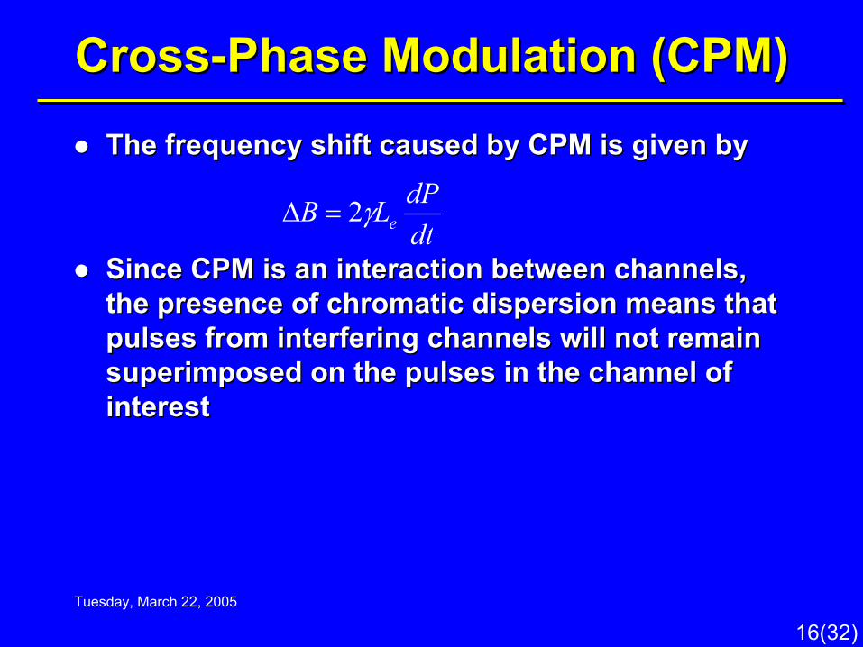
The frequency shift caused by CPM is given byThe frequency shift caused by CPM is given by
Since CPM is an interaction between channels, Since CPM is an interaction between channels, the presence of chromatic dispersion means that the presence of chromatic dispersion means that pulses from interfering channels will not remain pulses from interfering channels will not remain superimposed on the pulses in the channel of superimposed on the pulses in the channel of interestinterest
dtdPLB eγ2=∆

Tuesday, March 22, 2005
17(32)
FourFour--Photon Mixing (FPM)Photon Mixing (FPM)
FPM is a thirdFPM is a third--order nonlinearity caused order nonlinearity caused by the nonlinear refractive index of the by the nonlinear refractive index of the fiberfiberExample: If two signals with the Example: If two signals with the frequencies ffrequencies f11 and fand f22 are traveling in the are traveling in the fiber, two new cross products will appear, fiber, two new cross products will appear, 2f2f11--ff22 and 2fand 2f22--ff11. (Compare with IM3 and IP3 . (Compare with IM3 and IP3 for electrical circuits)for electrical circuits)The number of interfering products The number of interfering products increase rapidly with the number of increase rapidly with the number of signals (N) as signals (N) as ½½(N(N33--NN22))

Tuesday, March 22, 2005
18(32)
FourFour--Photon Mixing (FPM)Photon Mixing (FPM)
For signals with equal channelFor signals with equal channel--spacing the spacing the interfering signals will fall on top of the original interfering signals will fall on top of the original ones. They cannot be removed by any means.ones. They cannot be removed by any means.

Tuesday, March 22, 2005
19(32)
FourFour--Photon Mixing (FPM)Photon Mixing (FPM)Channel spacing strongly influences the Channel spacing strongly influences the magnitude of the FPM products, the further apart magnitude of the FPM products, the further apart the betterthe betterMixing efficiency is inversely proportional to the Mixing efficiency is inversely proportional to the fiber dispersion, more dispersion means less fiber dispersion, more dispersion means less FPMFPM

Tuesday, March 22, 2005
20(32)
FourFour--Photon Mixing (FPM)Photon Mixing (FPM)
a) System input a) System input power spectrum and power spectrum and eye diagrameye diagramb) System output, b) System output, equally spaced equally spaced channelschannelsc) System output, c) System output, unequally spaced unequally spaced channelschannels

Tuesday, March 22, 2005
21(32)
FourFour--Photon Mixing (FPM)Photon Mixing (FPM)
Dispersion management and unequal Dispersion management and unequal channel spacing are used for FPM channel spacing are used for FPM suppressionsuppressionBoth these techniques are perfectly Both these techniques are perfectly compatible and can preferably be used compatible and can preferably be used togethertogether

Tuesday, March 22, 2005
22(32)
Dispersion ManagementDispersion Management
Fiber chromatic dispersion plays a schizophrenic Fiber chromatic dispersion plays a schizophrenic role in WDM systemsrole in WDM systems–– On the one hand, it is the bane of short optical pulsesOn the one hand, it is the bane of short optical pulses–– On the other hand it is a useful tool to suppress FPMOn the other hand it is a useful tool to suppress FPM
Dispersion management ensures that no fiber in Dispersion management ensures that no fiber in the transmission path has a dispersionthe transmission path has a dispersion--zero zero wavelength close to the signal wavelengthwavelength close to the signal wavelengthHowever, the total accumulated dispersion However, the total accumulated dispersion between transmitter and receiver should be near between transmitter and receiver should be near zerozero

Tuesday, March 22, 2005
23(32)
Dispersion ManagementDispersion Management
Dispersion map for Dispersion map for shortest and longest shortest and longest wavelength:wavelength:–– Upper case: The spread in Upper case: The spread in
accumulated dispersion accumulated dispersion arises from the positive arises from the positive slope of dispersion in all slope of dispersion in all fibersfibers
–– Lower case: Conventional Lower case: Conventional fiber compensated by fiber compensated by dispersiondispersion--compensating compensating fiber (DCF) with negative fiber (DCF) with negative dispersiondispersion

Tuesday, March 22, 2005
24(32)
Modulation Instability (MI)Modulation Instability (MI)
MI can be described in two ways:MI can be described in two ways:–– In time domain it can be viewed as pulse breakup In time domain it can be viewed as pulse breakup
or or solitonsoliton formationformation–– In the frequency domain, MI can be described in In the frequency domain, MI can be described in
terms of parametric gain, or FPM phase matched terms of parametric gain, or FPM phase matched by SPM producing exponential gain for the mixing by SPM producing exponential gain for the mixing productsproducts

Tuesday, March 22, 2005
25(32)
Modulation Instability (MI)Modulation Instability (MI)
Modulation Modulation instability gain instability gain coefficient versus coefficient versus frequencyfrequency
Effect of Effect of parametric gain parametric gain when transmitting when transmitting a signal through a a signal through a fiberfiber

Tuesday, March 22, 2005
26(32)
Stimulated Raman Scattering (SRS)Stimulated Raman Scattering (SRS)
SRS is a nonlinear parametric interaction SRS is a nonlinear parametric interaction between light and molecular vibrationsbetween light and molecular vibrationsSRS is similar to SBS, but its threshold is SRS is similar to SBS, but its threshold is close to 1W nearly 1000 times higher than close to 1W nearly 1000 times higher than for SBSfor SBSSRS can couple different channels in a SRS can couple different channels in a WDM system and give arise to cross talkWDM system and give arise to cross talk

Tuesday, March 22, 2005
27(32)
Stimulated Raman Scattering (SRS)Stimulated Raman Scattering (SRS)The effect of SRS is usually first seen as that the The effect of SRS is usually first seen as that the shorter wavelength channels are robbed of shorter wavelength channels are robbed of power, and that power feeds the longer power, and that power feeds the longer wavelength channelswavelength channels

Tuesday, March 22, 2005
28(32)
Scaling NonlinearitiesScaling Nonlinearities
Issues of scaling of nonlinearities. Assume two Issues of scaling of nonlinearities. Assume two systems described in the table belowsystems described in the table below
DD22(l)=4D(l)=4D11(l)(l)DD11(l)(l)Dispersion mapDispersion map
0.5nm0.5nm1nm1nmChannel spacingChannel spacing
PP11/2/2PP11Power per channelPower per channel
5Gb/s5Gb/s10Gb/s10Gb/sBit rate per channelBit rate per channel
20201010Number of channelsNumber of channels
S2S220x5Gb/s20x5Gb/s
S1S110x10Gb/s10x10Gb/s

Tuesday, March 22, 2005
29(32)
Scaling NonlinearitiesScaling NonlinearitiesSince the power per channel for SSince the power per channel for S22 is lower, Sis lower, S22 is is less affected by the less affected by the ””singlesingle--channelchannel”” nonlinearities nonlinearities SBS and SRSSBS and SRSThe power of neighboring channels is less for SThe power of neighboring channels is less for S22and thereby Sand thereby S22 is less affected by CPMis less affected by CPMSS22 are less affected by FPM. Sare less affected by FPM. S11 has higher power has higher power and the mixing products generated by channels far and the mixing products generated by channels far away rapidly decreases, leading to the same away rapidly decreases, leading to the same number of number of ””relevantrelevant”” mixing products for Smixing products for S11 and Sand S22Since SSince S11 and Sand S22 have the same total power and have the same total power and bandwidth the SRS effect is the same for both bandwidth the SRS effect is the same for both systemssystems

Tuesday, March 22, 2005
30(32)
Scaling NonlinearitiesScaling Nonlinearities
The intuition that The intuition that ””multimulti--channelchannel””nonlinearities would affect Snonlinearities would affect S22 more than more than SS11 because of the larger number of because of the larger number of channels is wrongchannels is wrongFrom a fiber nonlinearity point of view, 20 From a fiber nonlinearity point of view, 20 5Gb/s channels is a better choice than 10 5Gb/s channels is a better choice than 10 10Gb/s channels to achieve a 100Gb/s 10Gb/s channels to achieve a 100Gb/s system.system.

Tuesday, March 22, 2005
31(32)
SummarySummaryTwo categories of nonlinearitiesTwo categories of nonlinearities–– Stimulated scattering (SBS, SRS)Stimulated scattering (SBS, SRS)–– Nonlinear index of refraction => distortion, cross modulation Nonlinear index of refraction => distortion, cross modulation
etc (SPM, CPM, FPM)etc (SPM, CPM, FPM)““SingleSingle--channelchannel”” nonlinearities:nonlinearities:–– SBSSBS–– SPMSPM
““MultiMulti--channelchannel”” nonlinearities:nonlinearities:–– CPMCPM–– FPMFPM–– SRSSRS

Tuesday, March 22, 2005
32(32)
SummarySummaryFrom a fiber nonlinearity point of view, 20 5Gb/s From a fiber nonlinearity point of view, 20 5Gb/s channels is a better choice than 10 10Gb/s channels is a better choice than 10 10Gb/s channels to achieve a 100Gb/s system.channels to achieve a 100Gb/s system.Fiber nonlinearities represent the fundamental Fiber nonlinearities represent the fundamental limiting on the amount of data that can be limiting on the amount of data that can be transferred on a single fibertransferred on a single fiberThere are several techniques to reduce the There are several techniques to reduce the effects from fiber nonlinearities effects from fiber nonlinearities Maximizing the effective fiber area is the most Maximizing the effective fiber area is the most common approach to reduce the fiber common approach to reduce the fiber nonlinearities nonlinearities