Fiber Design for ITS and Signalization · PDF fileFiber Design for ITS and Signalization...
47
Fiber Design for ITS and Signalization Projects W. Russell Allen, P.E. ITS Program Development Engineer FDOT State Traffic Engineering & Operations Office, TSM&O Program
Transcript of Fiber Design for ITS and Signalization · PDF fileFiber Design for ITS and Signalization...

Fiber Design for ITS and Signalization Projects
W. Russell Allen, P.E.
ITS Program Development EngineerFDOT State Traffic Engineering & Operations Office, TSM&O Program

PURPOSE
Provide insight into practices associated with fiber optic cable design including: specifications, pay-items, design standards, and industry practices.
• FDOT Standard Specifications for Road and Bridge Construction
• FDOT Design Standards
• Basis of Estimates (BOE)
• Plans Preparation Manual (PPM)

AGENDA – Fiber Optic Cable
• What it is
• How it works
• Why we use it
• Standards
• Terminology

AGENDA – Design Concepts
• High-level Design Concepts
• Layout for specific conditions
• Regulations important to our industry
Plans Specifications Estimates

AGENDA – Design Plans
• Plans layout
• Component parts (associated pay-items)
• Related details

AGENDA – Examples
• Various devices
• Connections to one another
• Associated pay-items (as applicable)
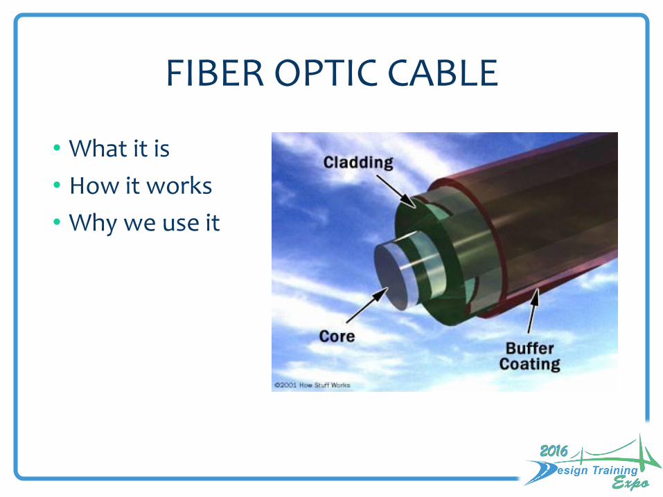
FIBER OPTIC CABLE
• What it is
• How it works
• Why we use it

FIBER OPTIC CABLE: What is it?
Multi-Mode Short-Haul Communications
Single-Mode Long-Haul Communications

FIBER OPTIC CABLE: What is it?

FIBER OPTIC CABLE: How does it work?

FIBER OPTIC CABLE: Why do we use it?
Extremely Low Loss• Transmit data over 120km without repeaters or
regeneration
Extremely High Bandwidth• 100 Gbps over a pair of fiber
• Data Security
• Resistance to EMI

FIBER OPTIC CABLE: Standards
TERMINOLOGY
COLOR CODE RULE OF SEPARATION

FIBER OPTIC CABLE: Terminology
• Backbone (or Trunk circuit)• Carries data from multiple network segments• Has the highest demand for capacity and requires the
highest level of protection
• Distribution (or Branch circuit)• Geographically branches off of the backbone and carries
data from a smaller portion of the network ~ may still have multiple segments
• Drops (or stub circuits) • Branches off of distribution and carries data at the local
equipment cabinet level
• Splices/Terminations
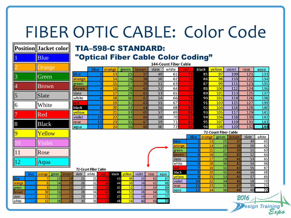
FIBER OPTIC CABLE: Color CodeTIA–598-C STANDARD:
"Optical Fiber Cable Color Coding”
Position Jacket color
1 Blue
2 Orange
3 Green
4 Brown
5 Slate
6 White
7 Red
8 Black
9 Yellow
10 Violet
11 Rose
12 Aqua

FIBER OPTIC CABLE: Color Code

Primary Fiber Design Concepts
• Minimize Exposure – Fiber Protection
• Capacity – Consider Future Growth & Scalability
• Design with Redundancy in Mind
• Link Budgets

Protection of Backbone Cable

Network Capacity
1/10/100Gb
100 Mb or 1/10 Gb
10/100 Mb
100 Mb or 1/10 Gb
10/100 Mb10/100 Mb(or 1 Gb)
(or 1 Gb)
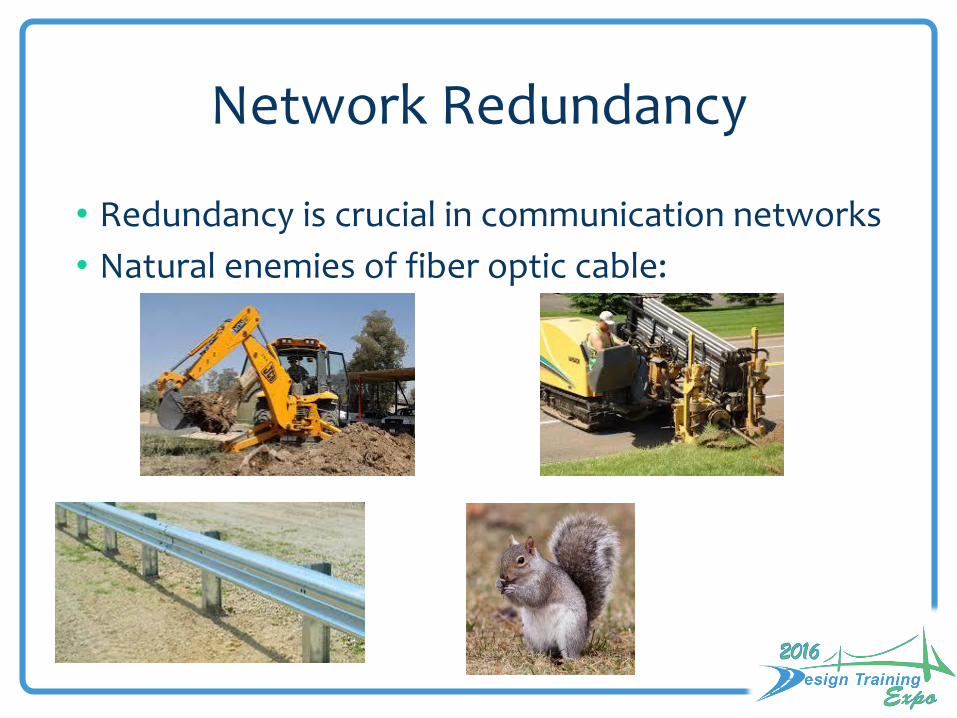
Network Redundancy
• Redundancy is crucial in communication networks
• Natural enemies of fiber optic cable:

Redundant Ring Topology
• Convergence
• Time to restore• Data lost
RTMCHUBA
HUBD
HUBC
HUBB
HUBE
Backbone
Distribution with Drops

Common Cable Disruptions

Limit Exposure
Whole cable
Piece ofthe
whole cable
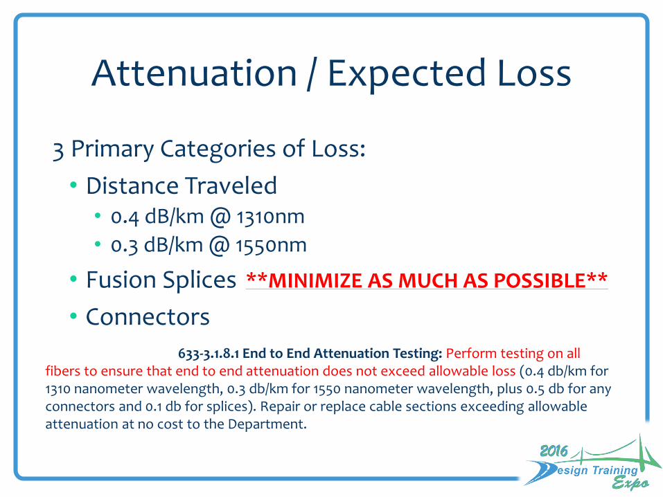
Attenuation / Expected Loss
3 Primary Categories of Loss:
• Distance Traveled• 0.4 dB/km @ 1310nm
• 0.3 dB/km @ 1550nm
• Fusion Splices
• Connectors
633-3.1.8.1 End to End Attenuation Testing: Perform testing on all fibers to ensure that end to end attenuation does not exceed allowable loss (0.4 db/km for 1310 nanometer wavelength, 0.3 db/km for 1550 nanometer wavelength, plus 0.5 db for any connectors and 0.1 db for splices). Repair or replace cable sections exceeding allowable attenuation at no cost to the Department.
**MINIMIZE AS MUCH AS POSSIBLE**

Example Link Loss Table
• Distance: 5 km
• Qty of Splices: 3
• Qty of Connectors: 2

Fiber Design Plans: Details
6 Primary Details (Best Practice):1) Plan Sheets
2) Network Block Diagrams
3) Splicing Details
4) Port Assignments
5) Link Loss Budget
6) Wiring Diagrams

Fiber Design Plans: Plan Sheets

Fiber Design Plans: Block Diagram
• Backbone• Distribution• Drops• Local Hubs• ITS/ATMS Devices• Legend

Fiber Design Plans: Splicing Detail
LOCATION

Fiber Design Plans: Port Assignments

Fiber Design Plans: Link Budget

! Consideration: Failover Loss Budget.
Fiber Design Plans: Link Budget
Tx(min) – Rx(min) --> Total Allowable Loss

Fiber Design Plans: Wiring Diagrams

Examples
• Fiber Optic Cable
• Connection Types
• Hardware for FOC
• Infrastructure for FOC

Examples: Fiber Optic Cable Specifications
SECTION 633COMMUNICATION CABLE
633-1 Description.
Furnish and install underground and aerial communication cable as shown in the
Plans and Design Standards.
633-2.1 Fiber Optic Cable and Connections.
633-2.1.1 Single Mode Fiber Optic Cable.
633-2.1.1.2 Buffer Tubes: …Ensure that each fiber optic
cable buffer tube contains 12 fibers per tube unless otherwise shown in the Plans.

Examples:Fiber Optic Cable Pay Items
StructureA= Operation 1 (Furnish & Install) 3 (Install) Furnished by FDOT or local agency; C=0 4 (Relocate) C=0 6 (Remove) C=0
B= Location 1 (Overhead) 2 (Underground)
C= Number of Fibers in Cable 1 (2 to 12) 2 (13 to 48) 3 (49 to 96) 4 (97 to 144)
633- 1 -ABC
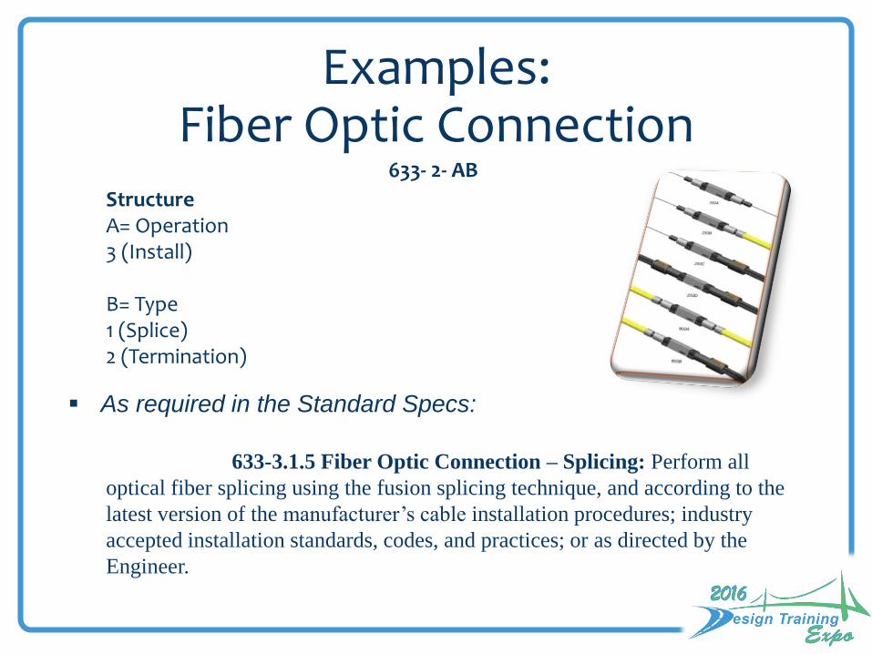
Examples: Fiber Optic Connection
As required in the Standard Specs:
StructureA= Operation 3 (Install)
B= Type 1 (Splice) 2 (Termination)
633-3.1.5 Fiber Optic Connection – Splicing: Perform all
optical fiber splicing using the fusion splicing technique, and according to the
latest version of the manufacturer’s cable installation procedures; industry
accepted installation standards, codes, and practices; or as directed by the
Engineer.
633- 2- AB

Examples: Fiber Optic Connection Hardware
633- 3- AB
StructureA= Operation 1 (Furnish & Install) 3 (Install) 4 (Relocate) 5 (Adjust /Modify)
B=Component 1 (Splice Enclosure) 2 (Splice Tray) 3 (Preterminated Connector Assembly) 4 (Buffer Tube Fan Out Kit) 5 (Patch Panel, Preterminated) 6 (Patch Panel, Field Terminated)7 (Connector Panel)
B=1 (Splice Enclosure)

Examples: Fiber Optic HardwareB=2 (Splice Tray)
B=3 (Preterminated Connector Assembly)* also known as a “Pigtail”
B=4 (Buffer Tube Fan-out Kit)
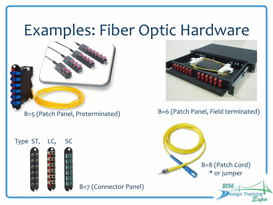
Examples: Fiber Optic Hardware
B=5 (Patch Panel, Preterminated) B=6 (Patch Panel, Field terminated)
B=7 (Connector Panel)
Type ST, LC, SC
B=8 (Patch Cord)* or jumper

Examples: Conduit
SECTION 630
CONDUIT630-1 Description.
Furnish and install conduit for traffic control signals and devices, highway
lighting, and other electrically powered or operated devices as shown in the
Contract Documents.
630-3.10 Route Markers: Install route markers for fiber optic cable
installations and ensure the following:
1. Markers are plumb and level and the notification information is clearly
visible when viewed from the side facing the roadway.
2. Markers are set within the right of way.
3. Markers are placed at a 1 foot offset from the conduit system.
4. The top of the marker post is a minimum of 5 feet and maximum of 6 feet
above the finish grade
5. Markers are spaced a maximum of 500 feet apart.
6. A clear line of sight is maintained from one marker to the next.

Structure
A = Operation
1 (Furnish & Install)
6 (Remove) B=5 only
B = Installation Method/Location
1 (Open Trench) Underground *
2 (Directional Bore) Underground or Under pavement*
3 (Jack & Bore) Typically under railroad*
4 (Aboveground)**
5 (Bridge Mount)**
*Measured as the horizontal length of the trench or bore; no
additional payment for multiple conduits in trench.
**Measured as the actual length of each conduit.
Examples: Conduit630- 2 - AB

Examples: Pull BoxesSECTION 635
PULL, SPLICE, AND JUNCTION BOXES
635-1 Description.
Furnish and install pull, splice, and junction boxes as shown in the Plans.
635-2.2.3 Dimensions: Unless otherwise shown in the Plans, provide pull and
splice boxes with the following dimensions.
For signalized intersection and lighting applications, provide pull boxes
with nominal cover dimensions of 13 inches wide by 24 inches long or larger and no
less than 12 inches deep. Ensure the inside opening area is a minimum of 240 square
inches and no inside dimension is less than 12 inches.
For fiber optic cable applications, provide pull boxes with nominal cover
dimensions of 24 inches wide by 36 inches long or larger and no less than 24 inches
deep.
Provide rectangular splice boxes with nominal cover dimensions of
30 inches wide by 60 inches long or larger and no less than 36 inches deep. Provide
round splice boxes with a nominal cover diameter of 36 inches or larger and no less
than 36 inches deep.

Examples: Pull and Splice Box635- 2- AB
Structure
A= Operation
1 (Furnish & Install)
3 (Install)
4 (Relocate) B=0
5 (Repair) maintenance use only
B= Cover Size; minimum dimensions,
per specification
1 (13 x 24)
2 (24 x 36) large size
3 (30” X 60”rectangular or 36” round) splice vault

Links / References
• FDOT Traffic Engineering and Operationshttp://www.dot.state.fl.us/trafficoperations/
• FDOT Program Management Office(Specifications and Estimates)http://www.dot.state.fl.us/programmanagement/default.shtm
• FDOT Design Standardshttp://www.dot.state.fl.us/rddesign/DesignStandards/Standards.shtm
• Approved Product Listhttps://fdotwp1.dot.state.fl.us/ApprovedProductList/Specifications
• Traffic Engineering Manual (TEM)http://www.dot.state.fl.us/trafficoperations/pdf/traffic_engineering_manual_revised_july_2011.pdf

Links / References
• Florida Intersection Design Guidehttp://www.dot.state.fl.us/rddesign/FIDG-Manual/FIDG.shtm
• Plans Preparation Manualhttp://www.dot.state.fl.us/rddesign/PPMManual/PPM.shtm
• Master Pay Item List / WebGatehttp://www.dot.state.fl.us/programmanagement/Estimates/BasisofEstimates/Default.shtm
• FHWA Manual on Uniform Traffic Control Devices (MUTCD)http://mutcd.fhwa.dot.gov/
You don’t have to know it all ….…. You just have to know where to find it

Questions?
FDOT
State Traffic Engineering and Operations Office TSM&O Program
Russell Allen, P.E.

Thank you