FHR Code Benchmarking White Paper, Integrated Research...
62
FHR Code Benchmarking White Paper, Integrated Research Project -2, Workshop 1 Fluoride-Salt-Cooled, High-Temperature Reactor Code Benchmarking White Paper Panel Members (U.S.) Edward Blandford (Univ. of New Mexico) David Carpenter (MIT) Richard Denning (Ohio State Univ.) Charles Forsberg (MIT) Max Fratoni (UCB) Hans Gougar (INL) David Holcomb (ORNL) Lin-wen Hu (MIT) Mike Laufer (UCB) Dave Moncton (MIT) Per Peterson (UCB) Brad Rearden (ORNL) Weiju Ren (ORNL) Kevin Robb (ORNL) Raluca Scarlat (UW) Kumar Sridharan (UW) Gerhard Strydom (INL) Xiaodong Sun (OSU) Richard Wright (Westinghouse) Gilles Youinou (INL) Grady Yoder (ORNL) Panel Members (International) In Cheol Bang (UNIST) Kun Chen (SINAP) Sungyeol Choi (UNIST) Zhimin Dai (SINAP) Ji-Hyun Kim (UNIST) Guimin Liu (SINAP) Wei Liu (SINAP) Naxiu Wang (SINAP) Guanyuan Wu (SINAP) Xiaohan Yu (SINAP) Hongjie Xu (SINAP) Yang Zou (SINAP) Students Nils Haneklaus (UCB, Facilitator) James Kendrick (UCB, Facilitator) Harry Andreades (UCB) Grant Buster (UCB) Zhangpeng Guo (UCB/Xian Jiaotong Univ.) Lakshana Huddar (UCB) Xin Wang (UCB) Nicolas Zweibaum (UCB) Lance Maul (ANSTO) Chris Edgar (GT) Pietro Avigni (GT) Becky Romatoski (MIT) Kaichao Sun (MIT) Chenglong Wang (MIT/Xian Jiaotong Univ.) Qiuping Lv (OSU) Joel Hughes (UNM) Floren Rubio (UNM) Guoping Cao (UW) Francesco Carotti (UW) Thomas Chrobak (UW) Kieran Dolan (UW) Michael Young (UW) Huali Wu (UW) Guiqiu (Tony) Zheng (UW) UCBTH-15-001 March 2015 Department of Nuclear Engineering University of California, Berkeley This research is being performed using funding received from the U.S. Department of Energy Office of Nuclear Energy’s Nuclear Energy University Programs.
Transcript of FHR Code Benchmarking White Paper, Integrated Research...

FHR Code Benchmarking White Paper, Integrated Research
Project -2, Workshop 1
Fluoride-Salt-Cooled, High-Temperature Reactor Code Benchmarking White
Paper Panel Members (U.S.)
Edward Blandford (Univ. of New Mexico)
David Carpenter (MIT)
Richard Denning (Ohio State Univ.)
Charles Forsberg (MIT)
Max Fratoni (UCB)
Hans Gougar (INL)
David Holcomb (ORNL)
Lin-wen Hu (MIT)
Mike Laufer (UCB)
Dave Moncton (MIT)
Per Peterson (UCB)
Brad Rearden (ORNL)
Weiju Ren (ORNL)
Kevin Robb (ORNL)
Raluca Scarlat (UW)
Kumar Sridharan (UW)
Gerhard Strydom (INL)
Xiaodong Sun (OSU)
Richard Wright (Westinghouse)
Gilles Youinou (INL)
Grady Yoder (ORNL)
Panel Members (International)
In Cheol Bang (UNIST)
Kun Chen (SINAP)
Sungyeol Choi (UNIST)
Zhimin Dai (SINAP)
Ji-Hyun Kim (UNIST)
Guimin Liu (SINAP)
Wei Liu (SINAP)
Naxiu Wang (SINAP)
Guanyuan Wu (SINAP)
Xiaohan Yu (SINAP)
Hongjie Xu (SINAP)
Yang Zou (SINAP)
Students
Nils Haneklaus (UCB, Facilitator)
James Kendrick (UCB, Facilitator)
Harry Andreades (UCB)
Grant Buster (UCB)
Zhangpeng Guo (UCB/Xian Jiaotong Univ.)
Lakshana Huddar (UCB)
Xin Wang (UCB)
Nicolas Zweibaum (UCB)
Lance Maul (ANSTO)
Chris Edgar (GT)
Pietro Avigni (GT)
Becky Romatoski (MIT)
Kaichao Sun (MIT)
Chenglong Wang (MIT/Xian Jiaotong Univ.)
Qiuping Lv (OSU)
Joel Hughes (UNM)
Floren Rubio (UNM)
Guoping Cao (UW)
Francesco Carotti (UW)
Thomas Chrobak (UW)
Kieran Dolan (UW)
Michael Young (UW)
Huali Wu (UW)
Guiqiu (Tony) Zheng (UW)
UCBTH-15-001
March 2015 Department of Nuclear Engineering
University of California, Berkeley
This research is being performed using funding received from the U.S. Department of Energy
Office of Nuclear Energy’s Nuclear Energy University Programs.
Fluoride-Salt-Cooled, High-Temperature Reactor Code Benchmarking White Paper 2 | 62
Preamble
The University of California, Berkeley; Massachusetts Institute of Technology; University of
Wisconsin, Madison; University of New Mexico; Georgia Institute of Technology; The Ohio
State University; and Texas A&M University, are collaborating to conduct a series of code-to-
code comparison and code validation exercises under two U.S. Department of Energy-sponsored
Integrated Research Projects (IRPs) to develop the technical basis to design and license fluoride-
salt-cooled, high-temperature reactors (FHRs).
The IRPs hosted a FHR Code Benchmarking expert workshop March 12-13, 2015, in
Berkeley, California, to review code benchmarking needs for FHRs and to obtain advice from
experts on best practices for code benchmarking. Experts from Oak Ridge National Laboratory,
Idaho National Laboratory, the Shanghai Institute of Applied Physics, the Ulsan Institute of
Science and Technology, and the IRP universities participated.
One of the key conclusions from the workshop was the recommendation to set up smaller
working groups to develop plans and coordinate benchmarking activities in three code
benchmarking areas: neutronics, thermal hydraulics, and materials chemistry, transport, and
activation. Relatively frequent working group meetings were recommended, via
videoconferencing or meetings co-located with technical meetings, as this is found to be the best
practice in previous benchmarking exercises. The full IRP workshops, when held on an
approximately annual basis, should include a day for breakout meetings by each of the working
groups, in addition to a day for the full IRP meeting.
This report summarizes results from the workshop, and recommends future IRP activities.
Fluoride-Salt-Cooled, High-Temperature Reactor Code Benchmarking White Paper 3 | 62
Executive Summary
Since the original concept of fluoride salt cooled, solid fueled high temperature reactors
(FHRs) was first proposed in 2002 [1], substantial progress has been made in understanding the
neutronics, thermal hydraulics, and materials issues posed by this technology. These studies
have found that FHRs are likely to have high levels of intrinsic safety, enabled by the high
volumetric heat capacity and intrinsically low pressure of fluoride salt coolants, and by the very
large thermal margins, exceeding 700°C, to fuel damage during transients and accidents.
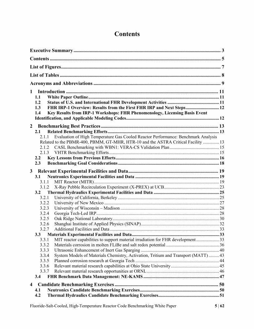
Given these attributes, in the United States significant effort has been made to develop the
scientific and technical basis to design and license FHRs, including work to develop pre-
conceptual FHR designs, as illustrated in Fig. P-1, to construct separate effect and integral effect
test facilities to validate thermal hydraulics models, and to test FHR structural materials in static
corrosion tests both in and out of reactors. In China, rapid parallel progress is underway in the
Thorium Molten Salt Reactor (TMSR) program to construct and run salt loops and to design a
10-MWt FHR test reactor, the TMSR-SF1, as well as a 2-MWt, electrically heated TMSR-
Simulator.
Fig. P-1. Four FHR preconceptual designs developed by ORNL and UC Berkeley
In 2012, the University of California, Berkeley; Massachusetts Institute of Technology; and
University of Wisconsin, Madison, conducted a series of expert technical workshops to assess
key areas important to the design and licensing of FHRs. These workshops identified major
design options and subsystems for FHRs, identified and reviewed key FHR phenomenology,
identified key licensing basis events, and recommended a range of general-purpose modeling
codes that can be adapted to use for simulation of FHR neutronics, thermal hydraulics, and
structural mechanics.
2008 900 MWt PB-AHTR
2010 125 MWt SmAHTR
2014 236 MWt Mk1 PB-FHR
2012 3600 MWt ORNL AHTR

Fluoride-Salt-Cooled, High-Temperature Reactor Code Benchmarking White Paper 4 | 62
To be used in safety analysis reports for license applications to the U.S. Nuclear Regulatory
Commission, simulation codes (referred to as “evaluation models, or EMs”) must be validated by
comparison with appropriate separate effect and integral system test data, and by benchmarks
with other codes, as described in detail in the NRC Regulatory Guide 1.203 [2]. The Guide
states,
“…an assessment should be made regarding the inherent capability of the EM to achieve the
desired results relative to the figures of merit derived from the [General Design Criteria].
Some of this assessment is best made during the early phase of code development to
minimize the need for later corrective actions. A key feature of the adequacy assessment is
the ability of the EM or its component devices to predict appropriate experimental behavior.
Once again, the focus should be on the ability to predict key phenomena, as described in the
first principle. To a large degree, the calculational devices use collections of models and
correlations that are empirical in nature. Therefore, it is important to ensure that they are used
within the range of their assessment.” (pg. 4)
This report lays out and prioritizes needs for EM assessment for FHRs, and recommends an
approach to code benchmarking efforts during the 3 years of upcoming IRP research. The
recommended approach involves forming three working groups, to establish and conduct EM
benchmarking exercises in three key areas of FHR phenomenology: neutronic; thermal
hydraulics; and materials corrosion, activation, tritium and transport (MATT).
Fluoride-Salt-Cooled, High-Temperature Reactor Code Benchmarking White Paper 5 | 62
Contents
Executive Summary ...................................................................................................................... 3
Contents ......................................................................................................................................... 5
List of Figures ................................................................................................................................ 7
List of Tables ................................................................................................................................. 8
Acronyms and Abbreviations ...................................................................................................... 9
1 Introduction .......................................................................................................................... 11 1.1 White Paper Outline .................................................................................................................. 11 1.2 Status of U.S. and International FHR Development Activities ............................................. 11 1.3 FHR IRP-1 Overview: Results from the First FHR IRP and Next Steps ............................. 12 1.4 Key Results from IRP-1 Workshops: FHR Phenomenology, Licensing Basis Event
Identification, and Applicable Modeling Codes ................................................................................. 12
2 Benchmarking Best Practices .............................................................................................. 13 2.1 Related Benchmarking Efforts ................................................................................................. 13
2.1.1 Evaluation of High Temperature Gas Cooled Reactor Performance: Benchmark Analysis
Related to the PBMR-400, PBMM, GT-MHR, HTR-10 and the ASTRA Critical Facility .............. 13 2.1.2 CASL Benchmarking with WBN1: VERA-CS Validation Plan ........................................... 15 2.1.3 VHTR Benchmarking Efforts ................................................................................................ 15
2.2 Key Lessons from Previous Efforts .......................................................................................... 16 2.3 Benchmarking Goal Considerations ........................................................................................ 18
3 Relevant Experimental Facilities and Data ........................................................................ 19 3.1 Neutronics Experimental Facilities and Data ......................................................................... 19
3.1.1 MIT Reactor (MITR) ............................................................................................................. 19 3.1.2 X-Ray Pebble Recirculation Experiment (X-PREX) at UCB................................................ 23
3.2 Thermal Hydraulics Experimental Facilities and Data ......................................................... 25 3.2.1 University of California, Berkeley ........................................................................................ 25 3.2.2 University of New Mexico .................................................................................................... 27 3.2.3 University of Wisconsin – Madison ...................................................................................... 28 3.2.4 Georgia Tech-Led IRP ........................................................................................................... 28 3.2.5 Oak Ridge National Laboratory............................................................................................. 30 3.2.6 Shanghai Institute of Applied Physics (SINAP) .................................................................... 32 3.2.7 Additional Facilities and Data ............................................................................................... 33
3.3 Materials Experimental Facilities and Data ............................................................................ 33 3.3.1 MIT reactor capabilities to support material irradiation for FHR development .................... 33 3.3.2 Materials corrosion in molten FLiBe and salt redox potential .............................................. 36 3.3.3 Ultrasonic Enhancement of Inert Gas Sparging .................................................................... 40 3.3.4 System Models of Materials Chemistry, Activation, Tritium and Transport (MATT) ......... 43 3.3.5 Planned corrosion research at Georgia Tech ......................................................................... 44 3.3.6 Relevant material research capabilities at Ohio State University .......................................... 45 3.3.7 Relevant material research opportunities at ORNL ............................................................... 46
3.4 FHR Benchmark Data Management: NE-KAMS .................................................................. 47
4 Candidate Benchmarking Exercises ................................................................................... 50 4.1 Neutronics Candidate Benchmarking Exercises ..................................................................... 50 4.2 Thermal Hydraulics Candidate Benchmarking Exercises ..................................................... 51

Fluoride-Salt-Cooled, High-Temperature Reactor Code Benchmarking White Paper 6 | 62
4.3 Materials Corrosion, Activation, Tritium, and Transport (MATT) Candidate
Benchmarking Exercises ...................................................................................................................... 54
5 Proposed Path Forward ....................................................................................................... 57 5.1 Technical Area Working Groups ............................................................................................. 57 5.2 Future Workshop Organization ............................................................................................... 58
6 References.............................................................................................................................. 57

Fluoride-Salt-Cooled, High-Temperature Reactor Code Benchmarking White Paper 7 | 62
List of Figures
Figure 2-1. VERA-CS Validation Assessment Matrix [5] ........................................................... 17 Figure 3-1. Drawing of the MITR ................................................................................................. 20
Figure 3-2: MITR Fuel Elements .................................................................................................. 20 Figure 3-3: Example of Wire Irradiation Experiment Conducted by Sun et al. in the MITR ...... 21 Figure 3-4: Comparison of the Neutron Spectrum in the MITR and typical FHR to Illustrate
Tritium Production ........................................................................................................................ 22 Figure 3-5: Planned Configuration for Tritium Measurements .................................................... 23
Figure 3-6: Overview of the XPREX Facility at UCB [14].......................................................... 24 Figure 3-7. Pebble-Bed Test Section for Heat Transfer Coefficient Measurement Experiments 25 Figure 3-8. FHR Primary Coolant Flow Paths for Forced and Natural Circulation Operation .... 25
Figure 3-9. 3-D Rendering of CIET 1.0 ........................................................................................ 26 Figure 3-10. UNM Heat Transfer Loop ........................................................................................ 28 Figure 3-11. OSU DRACS Test Facilities .................................................................................... 29 Figure 3-12: FS-1 Capsule Head................................................................................................... 35
Figure 3-13: FS-2 Entire Capsule (without head) ......................................................................... 35 Figure 3-14: Brief Overview of the Neutron Activation Analysis Tools and the Inert Glove Box
....................................................................................................................................................... 36 Figure 3-15: Atmosphere-controlled glove box, and molten salt dripping system ....................... 37 Figure 3-16: Surface and cross-sectional SEM images of Hastelloy N tested in molten FLiBe in
graphite crucible at 700°C for 1000 hours. ................................................................................... 38 Figure 3-17: UW beryllium reduction probe cutaway drawing .................................................... 39
Figure 3-18: Measured plateau region voltages shown to be repeatable through several runs .... 40 Figure 3-19: Brief Overview of Flow Cell 1 ................................................................................ 41
Figure 3-20: Brief Overview of Flow Cell 2 ................................................................................ 42 Figure 3-21: First Results of the High Speed Camera .................................................................. 42
Figure 3-22: Modulated Speed Rotator ......................................................................................... 45 Figure 4-1: TRIDENT Model of Materials, Tritium, and Corrosion Behavior in the FHR ......... 54 Figure 4-1: Material Candidate Benchmarking Exercise “Single Pebble” ................................... 55
Figure 4-2: Material Candidate Benchmarking Exercise “Pebble Bed Core” .............................. 56 Figure 4-3: Material Candidate Benchmarking Exercise “Loop” ................................................. 56
Fluoride-Salt-Cooled, High-Temperature Reactor Code Benchmarking White Paper 8 | 62
List of Tables
Table 3-1. Nominal Design Conditions of the HTDF................................................................... 29 Table 3-2. Nominal Design Conditions of the LTDF ................................................................... 30
Table 3-3. ONRL Liquid Salt Test Loop System Parameters ...................................................... 31 Table 3-4: Overview of Slots Available for Irradiation Experiments at the MITR ...................... 34 Table 3-5. Part List of UW Probe Design ..................................................................................... 39
Fluoride-Salt-Cooled, High-Temperature Reactor Code Benchmarking White Paper 9 | 62
Acronyms and Abbreviations
AHTR – Advanced High-Temperature Reactor
ANL – Argonne National Laboratory
ANS – American Nuclear Society
ARE – Aircraft Reactor Experiment
AOO – anticipated operational occurrences
ASME – American Society of Mechanical Engineers
ATWS – anticipated transient without scram
BDBE – beyond design basis event
BPV – Boiler and Pressure Vessel (Code)
CFR – U.S. Code of Federal Regulations
CFRC – carbon fiber-reinforced composite
CTF – Component Test Facility
DOE – U.S. Department of Energy
DRACS – Direct Reactor Auxiliary Cooling System
EAB – exclusion area boundary
EDMG –Extensive Damage Mitigation Guidelines
FHR – fluoride-salt-cooled, high-temperature reactor
FHTR – FHR Test Reactor
GDC – NRC General Design Criteria
GT-MHR – Gas-Turbine Modular Helium-Cooled Reactor
H2TS – hierarchical two-tier scaling (analysis)
HTGR – high-temperature gas-cooled reactor
HVAC – heating, ventilation, and air conditioning
IRP – Integrated Research Project
LBE – licensing basis events
LMFBR – Liquid Metal Fast Breeder Reactor
LMR – liquid metal reactor
LOFC – loss of forced circulation
LOHS – loss of heat sink
LS-VHTR – Liquid Salt Very High-Temperature Reactor
LWR – light-water reactor
MSBR – Molten Salt Breeder Reactor
MSR – molten salt reactor
MSRE – Molten Salt Reactor Experiment
NGNP – Next Generation Nuclear Plant
NRC – U.S. Nuclear Regulatory Commission
ORNL – Oak Ridge National Laboratory
PASSC – Plant, Areas, Systems, Subsystems, and Components
PB-AHTR – Pebble Bed Advanced High-Temperature Reactor
PBMR – Pebble Bed Modular Reactor
PCU – power conversion unit
PIRT – Phenomena Identification and Ranking Table
PRA – probabilistic risk assessment

Fluoride-Salt-Cooled, High-Temperature Reactor Code Benchmarking White Paper 10 | 62
PWR – pressurized-water reactor
SAMG – Severe Accident Management Guidelines
SAR – Safety Analysis Report
SDC – Safety Design Criteria
SFR – sodium-cooled fast reactor
Sm-AHTR – small modular Advanced High-Temperature Reactor
S-PRISM – Super-Power Reactor Innovative Small Module
SS – stainless steel
SSCs – systems, structures, and components
TEDE – total effective dose equivalent
TLRC – Top-Level Regulatory Criteria
TRISO – tristructural-isotropic
UCB – University of California, Berkeley

Fluoride-Salt-Cooled, High-Temperature Reactor Code Benchmarking White Paper 11 | 62
1 Introduction
This chapter serves as both an introduction to the structure and content of this whitepaper as
well as an introduction to the current state of international fluoride salt cooled, solid fuel high
temperature reactor (FHR) development. This white paper builds on the conclusions and results
from the first FHR Integrated Research Project (IRP-1) funded at the University of California,
Berkeley (UCB), the Massachusetts Institute of Technology (MIT), and the University of
Wisconsin, Madison (UW), by the U.S. Department of Energy.
1.1 White Paper Outline
This white paper covers a variety of topics important to the benchmarking of simulation
codes for modeling FHRs. The purpose of Chapter Two is to describe current best practices for
code benchmarking efforts. Key previous and current benchmarking efforts related to nuclear
energy and reactor technology are reviewed in Section 2.1 and key best practices are distilled in
Section 2.2. Section 2.3 defines the important problems to be addressed in the new IRP
benchmarking campaign, to enable validation of these simulation codes for licensing new reactor
technologies.
Chapter Three provides a review of key experimental facilities and data that can be used in
benchmarking efforts FHR simulation. The facilities and data are separated into the three distinct
technical areas in Sections 3.1 through 3.3. Also included in this chapter is Section 3.4, which is
a discussion of the integration of data produced in the FHR benchmarking effort into the ORNL
NE-KAMS data repository and management system.
Chapter Four provides a discussion of candidate benchmarking problems in the three
technical areas. These candidate benchmarking problems represent possible exercises to be
completed in this IRP based on the best practices and licensing goals from Chapter Two and the
relevant experimental facilities and data from Chapter Three. This is a key outcome of this
workshop.
Chapter Five is a recommendation of how to most effectively structure the new FHR IRP
(IRP-2) to complete this benchmarking effort. Workshop participants recommended that three
working groups, each focusing on one of the three technical areas, be formed and work on the
benchmarking exercises in their area throughout the three years of IRP-2. Future workshop
organization is discussed but detailed planning should be done after the three working groups are
created.
1.2 Status of U.S. and International FHR Development Activities
FHRs have the long-term potential to economically and reliably produce large quantities of
baseload and peaking power while employing full passive safety. Due to these characteristics,
FHR research in the U.S. currently benefits from multiple DOE initiatives and funding that
cover: 7Li Cost, Tritium Management, Structural Ceramics, Safety and Licensing, and Fuel Cost
and Qualification. In addition DOE as initiated an effort to consider building a new test reactor.
Three point designs are underway with one of those designs being a Fluoride-salt-cooled High-
Fluoride-Salt-Cooled, High-Temperature Reactor Code Benchmarking White Paper 12 | 62
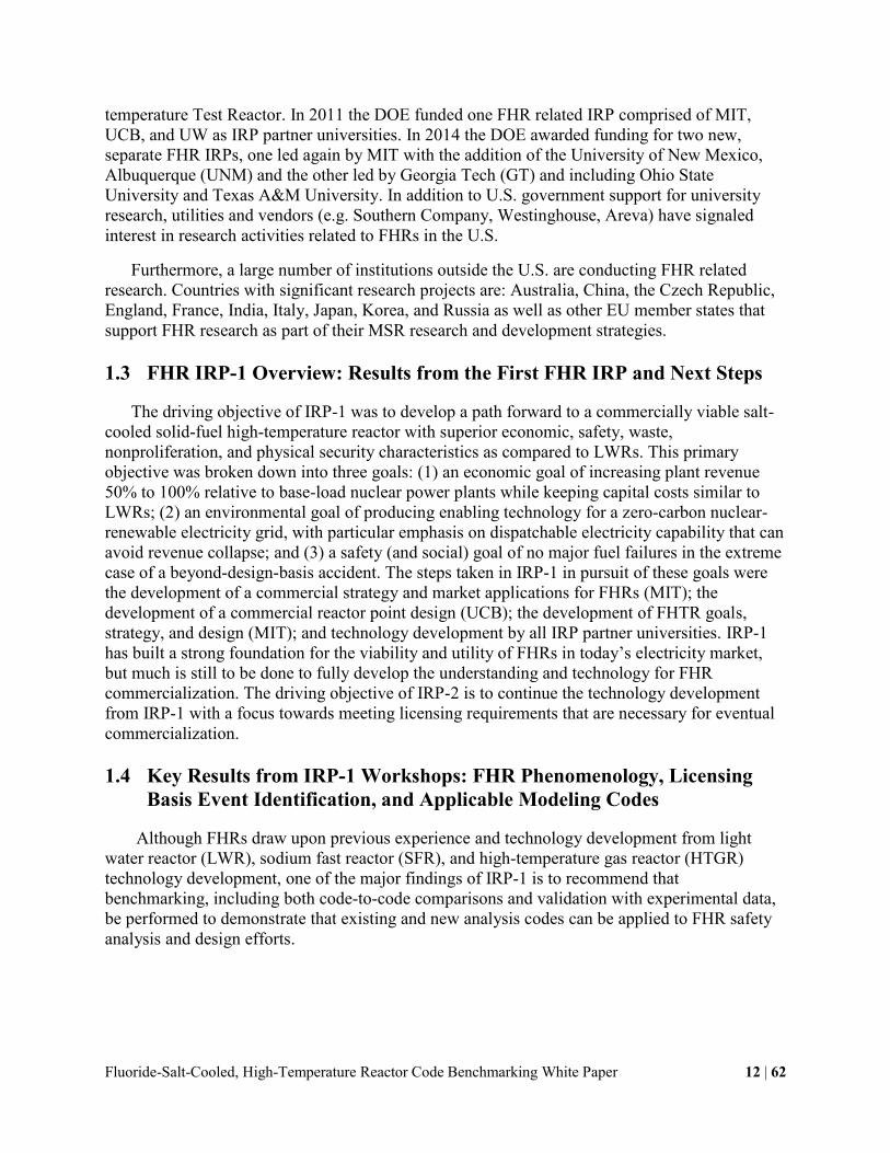
temperature Test Reactor. In 2011 the DOE funded one FHR related IRP comprised of MIT,
UCB, and UW as IRP partner universities. In 2014 the DOE awarded funding for two new,
separate FHR IRPs, one led again by MIT with the addition of the University of New Mexico,
Albuquerque (UNM) and the other led by Georgia Tech (GT) and including Ohio State
University and Texas A&M University. In addition to U.S. government support for university
research, utilities and vendors (e.g. Southern Company, Westinghouse, Areva) have signaled
interest in research activities related to FHRs in the U.S.
Furthermore, a large number of institutions outside the U.S. are conducting FHR related
research. Countries with significant research projects are: Australia, China, the Czech Republic,
England, France, India, Italy, Japan, Korea, and Russia as well as other EU member states that
support FHR research as part of their MSR research and development strategies.
1.3 FHR IRP-1 Overview: Results from the First FHR IRP and Next Steps
The driving objective of IRP-1 was to develop a path forward to a commercially viable salt-
cooled solid-fuel high-temperature reactor with superior economic, safety, waste,
nonproliferation, and physical security characteristics as compared to LWRs. This primary
objective was broken down into three goals: (1) an economic goal of increasing plant revenue
50% to 100% relative to base-load nuclear power plants while keeping capital costs similar to
LWRs; (2) an environmental goal of producing enabling technology for a zero-carbon nuclear-
renewable electricity grid, with particular emphasis on dispatchable electricity capability that can
avoid revenue collapse; and (3) a safety (and social) goal of no major fuel failures in the extreme
case of a beyond-design-basis accident. The steps taken in IRP-1 in pursuit of these goals were
the development of a commercial strategy and market applications for FHRs (MIT); the
development of a commercial reactor point design (UCB); the development of FHTR goals,
strategy, and design (MIT); and technology development by all IRP partner universities. IRP-1
has built a strong foundation for the viability and utility of FHRs in today’s electricity market,
but much is still to be done to fully develop the understanding and technology for FHR
commercialization. The driving objective of IRP-2 is to continue the technology development
from IRP-1 with a focus towards meeting licensing requirements that are necessary for eventual
commercialization.
1.4 Key Results from IRP-1 Workshops: FHR Phenomenology, Licensing
Basis Event Identification, and Applicable Modeling Codes
Although FHRs draw upon previous experience and technology development from light
water reactor (LWR), sodium fast reactor (SFR), and high-temperature gas reactor (HTGR)
technology development, one of the major findings of IRP-1 is to recommend that
benchmarking, including both code-to-code comparisons and validation with experimental data,
be performed to demonstrate that existing and new analysis codes can be applied to FHR safety
analysis and design efforts.
Fluoride-Salt-Cooled, High-Temperature Reactor Code Benchmarking White Paper 13 | 62
2 Benchmarking Best Practices
Determining the best practices and overall strategy is the first step in beginning a new
benchmarking campaign. This chapter reviews best practices for code benchmarking, obtained
from previous benchmarking efforts, which are relevant to benchmarking for FHR simulation.
2.1 Related Benchmarking Efforts
A thorough literature review of previous benchmarking activities is key to understanding the
fundamental steps of benchmarking and capturing the best practices for success. This section
provides an overview of selected previous benchmarking efforts that are related to performing
benchmarking studies for FHRs in some way and that were particularly informative of
benchmarking best practices.
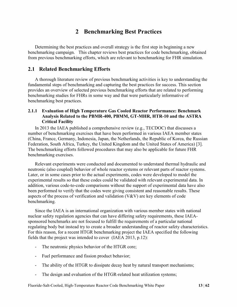
2.1.1 Evaluation of High Temperature Gas Cooled Reactor Performance: Benchmark
Analysis Related to the PBMR-400, PBMM, GT-MHR, HTR-10 and the ASTRA
Critical Facility
In 2013 the IAEA published a comprehensive review (e.g., TECDOC) that discusses a
number of benchmarking exercises that have been performed in various IAEA member states
(China, France, Germany, Indonesia, Japan, the Netherlands, the Republic of Korea, the Russian
Federation, South Africa, Turkey, the United Kingdom and the United States of America) [3].
The benchmarking efforts followed procedures that may also be applicable for future FHR
benchmarking exercises.
Relevant experiments were conducted and documented to understand thermal hydraulic and
neutronic (also coupled) behavior of whole reactor systems or relevant parts of reactor systems.
Later, or in some cases prior to the actual experiments, codes were developed to model the
experimental results so that these codes could be validated with relevant experimental data. In
addition, various code-to-code comparisons without the support of experimental data have also
been performed to verify that the codes were giving consistent and reasonable results. These
aspects of the process of verification and validation (V&V) are key elements of code
benchmarking.
Since the IAEA is an international organization with various member states with national
nuclear safety regulation agencies that can have differing safety requirements, these IAEA-
sponsored benchmarks are not focused to fulfill the requirements of a particular national
regulating body but instead try to create a broader understanding of reactor safety characteristics.
For this reason, for a recent HTGR benchmarking project the IAEA specified the following
fields that the project was intended to cover (IAEA 2013, p.12):
- The neutronic physics behavior of the HTGR core;
- Fuel performance and fission product behavior;
- The ability of the HTGR to dissipate decay heat by natural transport mechanisms;
- The design and evaluation of the HTGR-related heat utilization systems;

Fluoride-Salt-Cooled, High-Temperature Reactor Code Benchmarking White Paper 14 | 62
- Evaluation of the HTGR performance: Benchmark analysis related to initial testing of the
High Temperature Test Reactor (HTTR) and HTR-10.
These overall goals were defined in coordinated research projects related to the developments
of the PBMR from the beginning of 2000 to now conducted at IAEA over a period of several
years. Besides adding to the understanding of the safety characteristics of HTGRs, the
coordinated research projected supported code development that may be useful for future reactor
licensing efforts. The following objectives were provided by the projects’ participants:
- Validation of analytical codes and performance models to actual operating conditions of
HTGRs;
- Independent evaluation of benchmark problems for use in the Research and Development
(R&D) and safety programs for the HTR-10, PBMR, GT-MHR and the ASTRA
facilities;
- Investigation of analytical codes and models associated with the proposed GT-MHR and
PBMR400 gas turbine plants; - Investigation of code-to-experiment benchmarks
associated with the three-shaft gas turbine micro model (PBMM).
The benchmarking efforts were documented in a 690-page report, along with numerous
additional scientific reports and papers that describe the obtained results which are summarized
in the document itself as following:
- Reactor physics benchmark analysis of the ASTRA critical facility with respect to
development of the PBMR-400. These benchmarks include core height for criticality,
control rod worth and related differential reactivity and interference coefficients, and
investigation of critical parameters for differing heights of the pebble bed reactor.
- Code comparison benchmark problems of cell calculations (Kinf and isotope content vs.
burn up) and reactor physics of control rod worth and isothermal reactivity coefficients
for the GT-MHR fuelled with plutonium.
- - Code-to-experiment benchmark analysis related to the testing program of the HTR-10
plant including steady state temperature distribution with the reactor at full power, loss of
primary coolant flow without scram, and control rod withdrawal without scram.
- Neutronics and thermal hydraulic code comparison benchmarks for the PBMR-400.
- Micro model investigation of steady state and transient operating conditions for a three-
shaft gas turbine power conversion system.
As with many other IAEA reports, the TECDOC is freely available online1 and may be used
as a general guideline for similar benchmarking efforts related to a similar reactor system such as
the FHR.
1 http://www-pub.iaea.org/MTCD/Publications /PDF/TE-1694_web.pdf

Fluoride-Salt-Cooled, High-Temperature Reactor Code Benchmarking White Paper 15 | 62
2.1.2 CASL Benchmarking with WBN1: VERA-CS Validation Plan
The Consortium for Advanced Simulation of Light Water Reactors (CASL) is an Energy
Innovation Hub established in 2010 by the U.S. Department of Energy to, “provide modern
analysis tools that reliably model the effects of multiple processes occurring simultaneously
inside reactor cores, thereby predicting core behavior and helping to improve operational/safety
performance in light water reactors” [4]. Part of this overall mission is to develop a collection of
methods and software (M&S) tools called the Virtual Environment for Reactor Applications
(VERA) which also contains a core simulator component, VERA-CS. VERA-CS is meant to
provide a model of pressurized water reactor (PWR) cores with a high degree of flexibility in its
applications to parallel the capabilities of industry core simulators. Industry reactor core
simulators are typically licensed by the U.S. NRC and as such go through a rigorous process of
validation. Similar validation activities are thus considered necessary for VERA-CS to prove its
credibility, and a detailed validation plan has been developed [5].
A critical piece in formulating the validation plan for VERA-CS was the development of a
VERA-CS validation assessment matrix given in Figure 2-1. The VERA-CS validation
assessment matrix compares the required capabilities, features, and application range of VERA-
CS on the left of the matrix with proposed validation activities shown across the top of the
matrix. In this way, all capabilities are covered directly or indirectly by a least one activity.
Holes in this matrix can then be addressed in more detailed validation of individual physics
capabilities elsewhere. The matrix represents an effort to cover all possible validation
possibilities; in practice, due to budget and time limitations, the minimum set of validation
activities to provide confidence in VERA-CS reliability and accuracy will be prioritized. In
Figure 2-1, in general, the activities move from highest to lowest priority left to right for each
component.
The Watts Bar Nuclear Plant in Spring City, Tennessee, owned by TVA, is a CASL core
partner and was selected as CASL’s “Physical Reactor” for the initial benchmarking exercises.
Unit 1 was the most recent commercial nuclear power plant to come online and the completion
Unit 2 will cause Unit 2 to take Unit 1’s place in this designation. The startup of Watts Bar
Nuclear Unit 2 will provide very high quality instrument and test data for startup with a clean
core for VERA-CS validation exercises [5].
The clean startup data from Unit 2 is of course valuable for validation of VERA-CS, but is
one experimental data set among many in the scope of LWR operations, including startup. For
FHR modeling and simulation, a clean startup will necessarily be the first experimental data set
of its kind and of any reactor operations data sets in the FHR design space as no FHR has been
built to date. Understanding and adapting the validation plan for VERA-CS of Watts Bar Unit 2
is therefore very valuable for FHR validation plans, especially with the completion of the SINAP
TMSR-SF1 test reactor in the relatively near future.
2.1.3 VHTR Benchmarking Efforts
Various VHTR benchmarking studies were conducted is the US in support of the Next
Generation Nuclear Plant (NGNP) project (e.g. [6]–[8]). These documents may be of particular
interest for future FHR benchmarking as they are (1) publicly available and (2) consider the
licensing requirements of the NRC.

Fluoride-Salt-Cooled, High-Temperature Reactor Code Benchmarking White Paper 16 | 62
2.2 Key Lessons from Previous Efforts
Four key lessons were identified from previous benchmarking exercises:
1) Define purpose
2) Compose a mature benchmark
3) Secure funding
4) Motivate participation/participants.
These key lessons were identified as a result of an international benchmarking effort led by
the IAEA and may not all be applicable to the benchmarking efforts within IRP-2. Nevertheless,
it is believed that it is worthwhile to briefly discuss them here.
The purpose of the benchmarking exercise may be defined thoroughly before the actual
efforts begin to assure that the demands of all participants can be met. The purpose may be
purely scientific or more pragmatic in a way that it identifies the biggest licensing issues that
need to be addressed in order to receive the approval for construction from the associated
licensing body. Resulting from these purposes it should be investigated whether or not
challenges such as licensing issues can be addressed with currently available modeling tools or if
new modeling tools need to be developed, and if that is the case, if these new modeling tools
require additional experimental validation or if code-to-code comparisons with existing codes
would be sufficient. Needless to say the uncertainties of all these efforts should be taken into
account.
In a next step, a set of mature benchmarking exercises should be composed. Composing a
mature benchmark that provides the right amount of data but does not limit the participants’
ways of solving the exercises by assuming that certain tools will be used is an art form in itself.
In reality, designing benchmarking exercises is a continuous process in which benchmarking
participants give feedback and provide input to
- Correct errors
- Clarify
- Point out missing data
- Decode method specific data.
The benchmarking exercises should be kept as simple as possible to allow a wide range of
participants to join the benchmarking efforts.
During the whole benchmarking efforts funding needs to be secured to allow continuous
progress and provide certainty about the seriousness of the project.
Lastly the participation of benchmarking participants needs to be actively motivated. It was
found that scientific publications greatly attract and motivate participation in benchmarking
efforts.

Fluoride-Salt-Cooled, High-Temperature Reactor Code Benchmarking White Paper
17 | 6
2
Figure 2-1. VERA-CS Validation Assessment Matrix [5]
Fluoride-Salt-Cooled, High-Temperature Reactor Code Benchmarking White Paper 18 | 62
2.3 Benchmarking Goal Considerations
It is important to establish the goals of benchmarking in general, for the benchmarking of the
FHR proposed by this white paper, and how to balance these goals with the best practices
developed above to optimize the outcome using the limited time and resources available to the
IRP-2. Regulations and licensing concerns are significant challenges during the
commercialization of any reactor, and are therefore significant goals of IRP-2 efforts.
U.S. NRC Regulatory Guide 1.203 provides guidance on requirements for transient and
accident analysis models [2]. Specifically, the Evaluation Models Development and Assessment
Plan (EMDAP) is a systematic process for developing evaluation models for the analysis of
transient and accident behavior of reactors. The EMDAP suggests using existing general-purpose
codes to support development, design, and licensing of reactor technologies. Development and
application of more than one code, preferably by different research groups, is also encouraged.
The EMDAP provides good rationale for performing benchmarking studies for FHR technology,
and will be used to guide the benchmarking efforts. This should simplify licensing challenges in
the future.
The earlier FHR IRP-1 has put considerable effort into developing experimental programs in
neutronics, thermal hydraulics, and materials [9], [10]. These resources will be utilized to help
select models for benchmarking applications, as well as the forming of benchmarking exercises
that will be the most useful in pursuing licensing and fulfilling NRC regulations for the FHR. An
important tool identified in these previous efforts are Phenomena Identification and Ranking
Tables (PIRTs). PIRTs are a valuable tool that should be developed prior to benchmarking
exercises, given a mature experimental facility that is meant to provide experimental validation
data. As the facility changes and evolves to meet additional needs, an additional PIRT exercises
may need to be performed to verify that the facility is well-suited to address the phenomena of
interest. Face-to-face contact is needed for PIRT development, although video-conferencing can
be used to supplement this process. PIRTs should start with internal discussions, then outside
experts can be invited in when the initial plan has been drafted.
A second resource that may prove valuable will be the DOE/NRC Advanced Reactor Design
Criteria [11]. These criteria are still under development, but should provide a more flexible and
technology neutral framework for FHR licensing than the current, LWR-centric General Design
Criteria. Efforts on this front will be monitored and utilized as they are established.
FHR commercialization is the ultimate goal of the IRP-2; the guiding purpose of this effort is
to solve the key problems that vendors will face before they can build an FHR. Therefore, IRP-2
partner universities should focus on research and development of FHR technology, not bringing
the design to market. The path forward for the IRP is to bring FHR technology and
understanding to a point where vendors can pick up the efforts and continue with developing the
commercial technology.

Fluoride-Salt-Cooled, High-Temperature Reactor Code Benchmarking White Paper 19 | 62
X-PREX (UCB)
MITR (MIT)
HTGR/MSRE benchmarking
Code-to-code validation
3 Relevant Experimental Facilities and Data
A key component of benchmarking is the validation of codes and models against relevant
experimental data. There are several sources of experimental data in the FHR space, including
several facilities that have been or are currently operational. These experimental facilities and
data will be essential for performing validation of evaluation models for FHRs.
3.1 Neutronics Experimental Facilities and Data
Neutronics simulation will play a major role within IRP-2. Four major areas of interest for
neutronics simulations have so far been identified and may be investigated on in the IRP. The
four areas are briefly introduced below (in no particular order) and are explained in more detail
throughout this chapter:
- Flibe neutron moderation/absorption
- Fixed & Pebble/TRISO particle fuel
- Double heterogeneity
- Random pebble distribution
- Reactivity feedback
- Depletion
Because no FHR has been operated in the past to provide experimental neutronics data, IRP-
2 will use experimental results from neutronics experiments performed to study the behavior of
other types of reactors that share similarities with FHRs.
3.1.1 MIT Reactor (MITR)
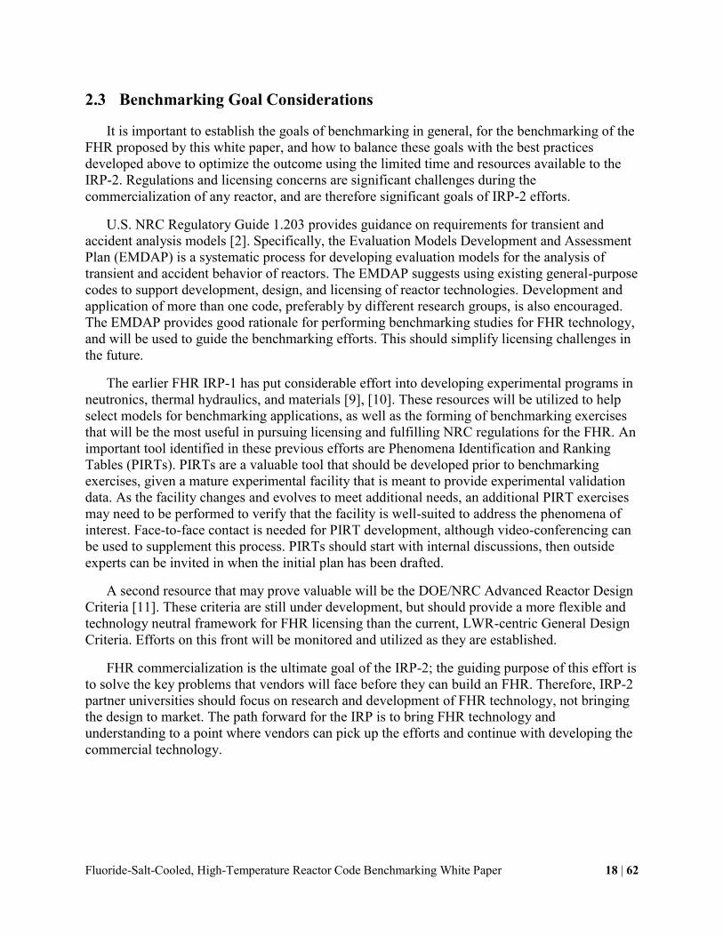
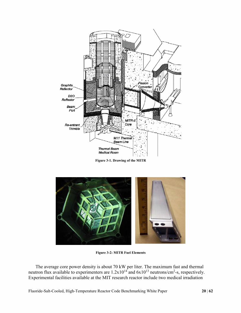
The MITR is a heavy-water reflected, light-water cooled and moderated nuclear test reactor
that utilizes flat, plate-type, finned, aluminum-clad fuel elements, as shown in Figs. 3-1 and 3-2
[12].
Fluoride-Salt-Cooled, High-Temperature Reactor Code Benchmarking White Paper 20 | 62
Figure 3-1. Drawing of the MITR
Figure 3-2: MITR Fuel Elements
The average core power density is about 70 kW per liter. The maximum fast and thermal
neutron flux available to experimenters are 1.2x10¹⁴ and 6x10¹³ neutrons/cm2-s, respectively.
Experimental facilities available at the MIT research reactor include two medical irradiation

Fluoride-Salt-Cooled, High-Temperature Reactor Code Benchmarking White Paper 21 | 62
rooms, beam ports, automatic transfer facilities (pneumatic tubes), and graphite-reflector
irradiation facilities. In addition, several in-core experimental facilities (ICSAs) are available. It
generally operates 24/7, except for planned outages for maintenance. The MITR encompasses a
number of inherent (i.e., passive) safety features, including negative reactivity temperature
coefficients of both the fuel and moderator; a negative void coefficient of reactivity; the location
of the core within two concentric tanks; the use of anti-siphon valves to isolate the core from the
effect of breaks in the coolant piping; a core-tank design that promotes natural circulation in the
event of a loss-of-flow accident; and the presence of a full containment. These features make it
an exceptionally safe facility.
Several neutronic codes are presently used by MIT students: CITATION, REBUS-
PC/DIF3D, MCNP5, and MCODE and may be available for code-to-code comparison or even
validation of small scale experiments in the reactor. These codes could for instance be used to
better understand the behavior of material important for FHRs under irradiation. Recent
experiments by Sun et al., shown in Fig. 3-3, provides an example how the MITR can provide
data to validate activation models for materials like iron-chromium-nickel wire [13].
Figure 3-3: Example of Wire Irradiation Experiment Conducted by Sun et al. in the MITR
Of particular interest for future FHR deployment are experiments related to the production,
transport, and control of tritium in the FHR flibe coolant, as tritium control is identified to be of
prime importance reactivity control in FHRs.

Fluoride-Salt-Cooled, High-Temperature Reactor Code Benchmarking White Paper 22 | 62
Figure 3-4 provides an overview of the neutron spectrum in a FHR, the MITR and the
lithium cross section.
Figure 3-4: Comparison of the Neutron Spectrum in the MITR and typical FHR to Illustrate Tritium Production
Validation of codes that predict tritium production in the MITR may be used to provide
confidence in FHR tritium source estimation. Figure 3-5 shows an experimental setup designed
for this purpose. Flibe would be inserted into the setup shown below and resulting tritium may be
monitored as shown.

Fluoride-Salt-Cooled, High-Temperature Reactor Code Benchmarking White Paper 23 | 62
Figure 3-5: Planned Configuration for Tritium Measurements
3.1.2 X-Ray Pebble Recirculation Experiment (X-PREX) at UCB
X-PREX seeks to demonstrate the viability of pebble fuel handling and reactivity control for
FHRs. The research results also improve the understanding of pebble motion in helium-cooled
reactors, as well as the general, fundamental understanding of low-velocity granular flows.
Successful use of pebble fuel in salt coolants would bring major benefits for high-temperature
reactor technology. Pebble fuels enable on-line refueling and operation with low excess
reactivity, and thus simpler reactivity control and improved fuel utilization. If fixed fuel designs
are used, the power density of salt-cooled reactors is limited to 10 MW/m3 to obtain adequate
duration between refueling, but pebble fuels allow power densities in the range of 20 to 30
MW/m3. This can be compared to the typical modular helium reactor power density of 5
MW/m3. Pebble fuels also permit radial zoning in annular cores and use of thorium or graphite
pebble blankets to reduce neutron fluences to outer radial reflectors and increase total power
production.
Combined with high power conversion efficiency, compact low-pressure primary and
containment systems, and unique safety characteristics including very large thermal margins

Fluoride-Salt-Cooled, High-Temperature Reactor Code Benchmarking White Paper 24 | 62
(>500°C) to fuel damage during transients and accidents, salt-cooled pebble fuel cores offer the
potential to meet the major goals of the Advanced Reactor Concepts Development program to
provide electricity at lower cost than light water reactors with improved safety and system
performance.
Figure 3-6 provides a brief overview of the facility and its visualization capabilities. Further
information can be obtained from Laufer and Buster [14].
Visual Image Sequence:
X-Ray Image Sequence:
Figure 3-6: Overview of the XPREX Facility at UCB [14]
Fluoride-Salt-Cooled, High-Temperature Reactor Code Benchmarking White Paper 25 | 62
3.2 Thermal Hydraulics Experimental Facilities and Data
The set of experimental facilities and data in the thermal hydraulics space for FHRs is
diverse and growing. The primary experimental facilities are within the IRPs and are located at
UCB, UNM, OSU, and UW. Other experimental data relevant to FHR benchmarking comes
principally come from ORNL and SINAP, the two major research institutions researching and
developing molten salt reactor technology associated with FHRs.
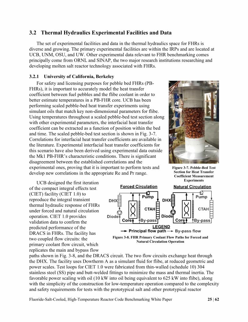
3.2.1 University of California, Berkeley
For safety and licensing purposes for pebble bed FHRs (PB-
FHRs), it is important to accurately model the heat transfer
coefficient between fuel pebbles and the flibe coolant in order to
better estimate temperatures in a PB-FHR core. UCB has been
performing scaled pebble-bed heat transfer experiments using
simulant oils that match key non-dimensional parameters for flibe.
Using temperatures throughout a scaled pebble-bed test section along
with other experimental parameters, the interfacial heat transfer
coefficient can be extracted as a function of position within the bed
and time. The scaled pebble-bed test section is shown in Fig. 3-7.
Correlations for interfacial heat transfer coefficients are available in
the literature. Experimental interfacial heat transfer coefficients for
this scenario have also been derived using experimental data outside
the Mk1 PB-FHR’s characteristic conditions. There is significant
disagreement between the established correlations and the
experimental ones, proving that it is important to perform tests and
develop new correlations in the appropriate Re and Pr range.
UCB designed the first iteration
of the compact integral effects test
(CIET) facility (CIET 1.0) to
reproduce the integral transient
thermal hydraulic response of FHRs
under forced and natural circulation
operation. CIET 1.0 provides
validation data to confirm the
predicted performance of the
DRACS in FHRs. The facility has
two coupled flow circuits: the
primary coolant flow circuit, which
replicates the main and bypass flow
paths shown in Fig. 3-8, and the DRACS circuit. The two flow circuits exchange heat through
the DHX. The facility uses Dowtherm A as a simulant fluid for flibe, at reduced geometric and
power scales. Test loops for CIET 1.0 were fabricated from thin-walled (schedule 10) 304
stainless steel (SS) pipe and butt-welded fittings to minimize the mass and thermal inertia. The
favorable power scaling with oil (10 kW into oil being equivalent to 625 kW into flibe), along
with the simplicity of the construction for low-temperature operation compared to the complexity
and safety requirements for tests with the prototypical salt and other prototypical reactor
Figure 3-7. Pebble-Bed Test
Section for Heat Transfer
Coefficient Measurement
Experiments
Figure 3-8. FHR Primary Coolant Flow Paths for Forced and
Natural Circulation Operation

Fluoride-Salt-Cooled, High-Temperature Reactor Code Benchmarking White Paper 26 | 62
coolants, were a key element in enabling the CIET 1.0 facility to be constructed at much lower
cost than previous IETs for other reactor classes.
Because the designs of FHR commercial prototype reactors will evolve, inherent distortions
will exist between the CIET 1.0 facility and future FHR commercial prototype reactors. For
transient response, such distortions may arise from non-matched relative coolant residence times
between future FHRs and CIET 1.0 sub-systems, as well as the use of reduced flow area SS
piping with non-scaled thermal inertia in CIET 1.0. However, while CIET 1.0 was scaled based
on the earlier design of a 900-MWth channel-type pebble-bed advanced high-temperature reactor
(PB-AHTR), and the pre-conceptual design of a 236-MWth Mk1 PB-FHR was completed after
scaling and design of CIET 1.0 were already finalized, elevations of the main heat sources and
sinks in CIET 1.0 and the Mk1 PB-FHR design reveal a reasonable agreement between the
scaled model and prototype. Therefore, CIET 1.0 will provide useful validation data for integral
transient behavior of a generic set of FHRs, and given the low cost of the CIET facility, final
code validation for a future commercial prototype plant would likely include construction of a
new CIET-type loop scaled to closely match the prototypical design.
For lack of detailed heat exchanger
designs when scaling was performed and
design decisions were made for CIET 1.0,
the heat exchangers in the system are not
scaled to any prototypical heat exchanger.
Instead, their designs are based on functional
requirements in terms of heat transfer
performance, and only relative elevations of
the heat sources and sinks are scaled to the
900-MWth modular PB-AHTR. However,
the ability to control fan speeds on the two
oil-to-air heat exchangers using variable
frequency drives (VFDs), as well as to
interchange the current oil-to-oil heat
exchanger that couples the primary and
DRACS flow loops with another scaled heat
exchanger design, leaves great flexibility in
heat removal options for the CIET 1.0
system. Similar to the heat exchangers, the
primary pump on CIET 1.0 is not scaled to
any prototypical pump. Instead, its design is
based on functional requirements in terms of
pump head and resulting flow rates in the
system. All instrumentation, as well as the
computer-controlled power supply and VFDs
are integrated through the LabVIEW
software and manually or automatically
controlled from a central computer station.
Figure 3-9 shows the computer-aided design Figure 3-9. 3-D Rendering of CIET 1.0

Fluoride-Salt-Cooled, High-Temperature Reactor Code Benchmarking White Paper 27 | 62
rendering of the CIET 1.0 loop with the main components labeled.
Between 2011 and 2014, CIET 1.0 was designed, fabricated, filled with Dowtherm A oil and
operated. Isothermal pressure drop tests were completed, with extensive pressure data collection
to determine friction losses in the system. CIET-specific friction loss correlations were compared
with handbook values, and empirically measured values were implemented in the system codes
that are to be validated by CIET data. The project then entered a phase of heated tests, from
parasitic heat loss tests to more complex feedback control tests and natural circulation
experiments. In parallel, UCB has been developing thermal hydraulic models to predict FHR
steady-state characteristics and transient response for a set of reference LBEs. The general
strategy is to rely on existing general-purpose thermal hydraulic codes with a significant V&V
basis for design and licensing by the U.S. Nuclear Regulatory Commission, such as RELAP5.
However, UCB has also been developing a one-dimensional FHR advanced natural circulation
analysis (FANCY) code for CIET 1.0 and FHR natural circulation modeling. FANCY results
will be compared with RELAP5 and validated by data from CIET 1.0. Validation data will
include steady-state forced and coupled natural circulation data in the primary loop and the
DRACS loop, and thermal transients data (e.g., startup, shutdown, loss of forced circulation with
scram and loss of heat sink with scram) [15].
3.2.2 University of New Mexico
Due to the high volumetric heat capacity of fluoride salts, FHR heat exchangers commonly
operate in the transition and laminar flow regimes where heat transfer coefficients can depend
strongly on Reynolds number (Re) and potentially on Grashof number (Gr). Several reduced-
scale experiments investigating heat exchanger phenomenology for FHRs are currently
underway at UNM. A multi-flow regime heat transfer loop, shown in Fig. 3-10, has been
constructed for use with Dowtherm A to collect data and validate current heat transfer
correlations (or develop new, when necessary) for several promising heat exchanger concepts. In
parallel, a simple water loop investigating hydrodynamics was constructed and has been testing
directional heat exchanger concepts for the DHX, which have the potential to help minimize
parasitic heat losses during normal operation of the plant and enhance heat extraction during
accidents.
The heat transfer loop is being used to perform a number of SETs on heat exchanger
concepts. It was initially designed to test bayonet-style heat exchangers, which are inserted into
the FHR coolant pool from the top and feature both the secondary (tube-side) feeder and outlet
tubes attached to the top of the heat exchanger. Validation data will be collected for two
conventional bayonet-style configurations: plain tubes and twisted tubes. Twisted tubes are a
particularly promising technology to the development of the FHR due to their enhanced heat
transfer as well as their self-supporting design, which eliminates the need for baffles and reduces
hot spots and tube vibration.
The loop will be able to match shell-side Re and Pr for the primary-to-DRACS heat
exchanger (DHX), as well as have the capability to test a range of Gr, and by extension, Rayleigh
(Ra) and Richardson (Ri) numbers owing to the flexibility of the temperature conditions.

Fluoride-Salt-Cooled, High-Temperature Reactor Code Benchmarking White Paper 28 | 62
The same plain and twisted tube bayonet
heat exchangers will also be tested in a novel
directionally enhanced shell concept.
Because the DRACS is passive and always
operating, heat is perpetually being removed
from the primary coolant through the DHX.
These parasitic heat losses lower the
effective reactor outlet temperature during
normal operation, reducing the efficiency of
the FHR. The hydrodynamics of a
directional DHX has been empirically
investigated using a simple water loop and
has shown promising initial results. The
design will be further optimized in
conjunction with computational fluid
dynamics and the resulting shell design will
be implemented in the heat transfer loop and
tested with the plain and twisted tube
bundles.
Finally, the loop will be configured to
test and provide data for a double-wall twisted-tube heat exchanger. Due to the relatively large
quantity of tritium generated in FHRs relative to other reactor concepts and the high operating
temperature, which encourages the transport of tritium through and out of the system, the use of
double-wall heat exchangers utilizing an intermediate fluid such as lithium to capture the tritium
is under consideration. By using a twisted outer tube, it is possible to take advantage of the
higher shell-side heat transfer coefficients and more uniform shell-side flow while also
enhancing heat transfer to the intermediate fluid flowing in the annulus. Two configurations will
be tested at UNM: a double-wall exchanger with inner plain tube/outer plain tube and a double-
wall exchanger with inner plain tube/outer twisted tube to determine the heat transfer
enhancement possible with the twisted-tube version [15].
3.2.3 University of Wisconsin – Madison
The University of Wisconsin – Madison was primarily involved in investigating materials
phenomena in the FHR class in the previous IRP. However, as part of this IRP-2, a portion of
their research and study will be developing thermal hydraulic loops for the investigation of
thermal hydraulic phenomena present in FHRs as well as continuing their investigations of the
molten salt chemistry and corrosion. Fluid loops are able to be used for SETs as well as IETs.
3.2.4 Georgia Tech-Led IRP
A high-temperature DRACS test facility (HTDF) that is being constructed at The Ohio State
University (OSU) is shown in Fig. 3-11 (in red), along with the low-temperature DRACS test
facility (LTDF) that is currently in operation (Fig. 3-11 in gray). Both the HTDF and LTDF are
scaled down from a 200-kW prototypic DRACS design for a pebble bed reactor design by
following a rigorous scaling analysis [16]. The HTDF employs FLiNaK and KF-ZrF4 as the
primary and secondary coolants, respectively. With the HTDF, the DRACS performance in
Figure 3-10. UNM Heat Transfer Loop

Fluoride-Salt-Cooled, High-Temperature Reactor Code Benchmarking White Paper 29 | 62
terms of its capability of removing decay heat under prototypic reactor conditions can be
evaluated. 1-1/2” and 1-1/4” Schedule 40 pipes are
used for the primary and secondary loops,
respectively. The HTDF core is simulated with 7
electric cartridge heaters with a total nominal power
of 10 kW. The DHX employs a shell-and-tube heat
exchanger design containing 80 5/8” BWG-18 tubes
at a length of 0.325 m. Due to the large temperature
difference between the secondary salt and ambient
air, plain tubes are used for the NDHX. A total of 36
1/2” BWG-16 tubes are adopted in a staggered array
in two rows. A vortex diode design that will exhibit
desired pressure drop characteristics for both the
forward and reverse flow directions has been
obtained via a parametric CFD study [17], [18]. The
diode design employs converging/diverging nozzles
and a disk-shape chamber with a diameter of 6.6 cm
and thickness of 1.56 cm [18]. In addition, a
cantilever sump pump for high-temperature
applications has also been employed in the HTDF.
The nominal design conditions for steady-state
operation of the HTDF are summarized in Table 3-1.
The HTDF will be fully instrumented with gauge pressure transmitters to monitor the cover
gas pressure in all the salt tanks, capacitance level sensors to monitor the tank salt levels, and
thermocouples (N-type) to measure/monitor the salt temperatures along the loop, as well as in
the tanks. High-temperature clamp-on ultrasonic flow meters from Flexim will be employed to
measure the flow rates. The same flow meters have been provided to ORNL for a similar
application with temperature up to 700°C. For the differential pressure measurement, in-house
designs utilizing commercial differential pressure transmitters have been developed, which will
require accurate control of the salt-Ar interface in the pressure sensing lines.
Table 3-1. Nominal Design Conditions of the HTDF
Primary Salt
(FLiNaK)
Secondary Salt (KF-
ZrF4) Air
hotT (°C) 722.1 665.3 110.0
coldT (°C) 677.9 589.7 40.0
T (°C) 44.2 75.6 60.0
m (kg/s) 0.120 0.127 0.142
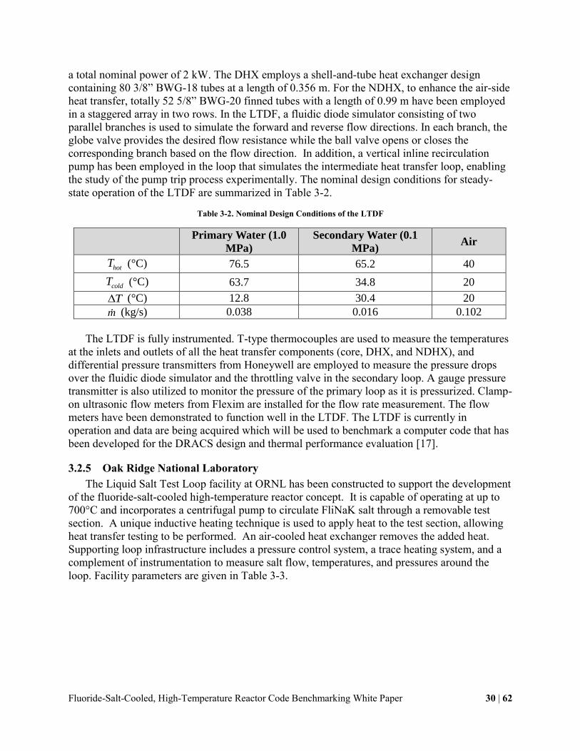
The LTDF uses water as both the primary and secondary coolants. The LTDF is intended to
examine the couplings among the natural circulation/convection loops, provide OSU experience
before building the HTDF. 1-1/4” and 3/4” Schedule 40 pipes are used for the primary and
secondary loops, respectively. The LTDF core is simulated with 3 electric cartridge heaters with
Figure 3-11. OSU DRACS Test Facilities
Fluoride-Salt-Cooled, High-Temperature Reactor Code Benchmarking White Paper 30 | 62
a total nominal power of 2 kW. The DHX employs a shell-and-tube heat exchanger design
containing 80 3/8” BWG-18 tubes at a length of 0.356 m. For the NDHX, to enhance the air-side
heat transfer, totally 52 5/8” BWG-20 finned tubes with a length of 0.99 m have been employed
in a staggered array in two rows. In the LTDF, a fluidic diode simulator consisting of two
parallel branches is used to simulate the forward and reverse flow directions. In each branch, the
globe valve provides the desired flow resistance while the ball valve opens or closes the
corresponding branch based on the flow direction. In addition, a vertical inline recirculation
pump has been employed in the loop that simulates the intermediate heat transfer loop, enabling
the study of the pump trip process experimentally. The nominal design conditions for steady-
state operation of the LTDF are summarized in Table 3-2.
Table 3-2. Nominal Design Conditions of the LTDF
Primary Water (1.0
MPa)
Secondary Water (0.1
MPa) Air
hotT (°C) 76.5 65.2 40
coldT (°C) 63.7 34.8 20
T (°C) 12.8 30.4 20
m (kg/s) 0.038 0.016 0.102
The LTDF is fully instrumented. T-type thermocouples are used to measure the temperatures
at the inlets and outlets of all the heat transfer components (core, DHX, and NDHX), and
differential pressure transmitters from Honeywell are employed to measure the pressure drops
over the fluidic diode simulator and the throttling valve in the secondary loop. A gauge pressure
transmitter is also utilized to monitor the pressure of the primary loop as it is pressurized. Clamp-
on ultrasonic flow meters from Flexim are installed for the flow rate measurement. The flow
meters have been demonstrated to function well in the LTDF. The LTDF is currently in
operation and data are being acquired which will be used to benchmark a computer code that has
been developed for the DRACS design and thermal performance evaluation [17].
3.2.5 Oak Ridge National Laboratory
The Liquid Salt Test Loop facility at ORNL has been constructed to support the development
of the fluoride-salt-cooled high-temperature reactor concept. It is capable of operating at up to
700°C and incorporates a centrifugal pump to circulate FliNaK salt through a removable test
section. A unique inductive heating technique is used to apply heat to the test section, allowing
heat transfer testing to be performed. An air-cooled heat exchanger removes the added heat.
Supporting loop infrastructure includes a pressure control system, a trace heating system, and a
complement of instrumentation to measure salt flow, temperatures, and pressures around the
loop. Facility parameters are given in Table 3-3.

Fluoride-Salt-Cooled, High-Temperature Reactor Code Benchmarking White Paper 31 | 62
Table 3-3. ONRL Liquid Salt Test Loop System Parameters
ONRL Liquid Salt Test Loop Parameter Description
Salt FLiNaK
Operating Temperature 700oC
Flow Rate ≤ 4.5 kg/s
≈ 3.5 m/s (1 in. pipe ID)
Operating Pressure Near Atmospheric
Material of Construction Inconel 600
Operating Run Time Life 2+ years
Primary Piping ID 2.667 cm (1.05 in)
Loop Volume 72 liters
Trace Heating ≈ 20 kW
Thermocouples 47 (8 in bed)
Pressure Gauges 1 in salt
2 in gas spaces
Flow Rate Measurement Ultrasonic Flow Meter
Salt Level 1 radar – sump tank
2 H-T/C – sump and surge tanks (1 each)
Fluoride-Salt-Cooled, High-Temperature Reactor Code Benchmarking White Paper 32 | 62
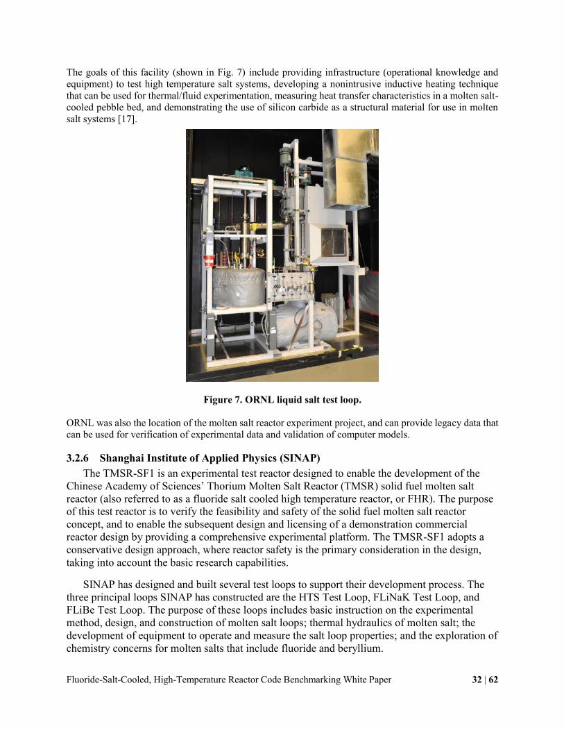
The goals of this facility (shown in Fig. 7) include providing infrastructure (operational knowledge and
equipment) to test high temperature salt systems, developing a nonintrusive inductive heating technique
that can be used for thermal/fluid experimentation, measuring heat transfer characteristics in a molten salt-
cooled pebble bed, and demonstrating the use of silicon carbide as a structural material for use in molten
salt systems [17].
Figure 7. ORNL liquid salt test loop.
ORNL was also the location of the molten salt reactor experiment project, and can provide legacy data that
can be used for verification of experimental data and validation of computer models.
3.2.6 Shanghai Institute of Applied Physics (SINAP)
The TMSR-SF1 is an experimental test reactor designed to enable the development of the
Chinese Academy of Sciences’ Thorium Molten Salt Reactor (TMSR) solid fuel molten salt
reactor (also referred to as a fluoride salt cooled high temperature reactor, or FHR). The purpose
of this test reactor is to verify the feasibility and safety of the solid fuel molten salt reactor
concept, and to enable the subsequent design and licensing of a demonstration commercial
reactor design by providing a comprehensive experimental platform. The TMSR-SF1 adopts a
conservative design approach, where reactor safety is the primary consideration in the design,
taking into account the basic research capabilities.
SINAP has designed and built several test loops to support their development process. The
three principal loops SINAP has constructed are the HTS Test Loop, FLiNaK Test Loop, and
FLiBe Test Loop. The purpose of these loops includes basic instruction on the experimental
method, design, and construction of molten salt loops; thermal hydraulics of molten salt; the
development of equipment to operate and measure the salt loop properties; and the exploration of
chemistry concerns for molten salts that include fluoride and beryllium.

Fluoride-Salt-Cooled, High-Temperature Reactor Code Benchmarking White Paper 33 | 62
The TMSR-SF0 is an electrically heated simulator for solid fuel molten salt reactors. As a
comprehensive experimental platform, its primary function is to provide data and experience to
support TMSR-SF1 licensing and provide practical experience for SF1 design, start up, operation
and maintenance, including verification of TMSR -SF1 thermal-hydraulic design and safety
programs and other key engineering and technical solutions; testing and test SF1 key equipment;
to simulate and experiment SF1 start up, operation and accident conditions; and maintenance.
TMSR-SF0 will also provide experimental evidence for verification and validation for solid fuel
molten salt reactor thermal hydraulics and safety analysis codes.
Based on the above considerations, the TMSR-SF0 is designed as a full-scale, 1:1
geometrically scaled simulator for the TMSR-SF1. The key materials, technologies and
equipment used in the SF0 have the same design with SF1, and the plant layout is also basically
the same. The main differences between the SF0 and SF1 are that SF0 graphite fuel pebbles are
not loaded with nuclear fuel, the coolant is heated by electrical heating elements with a total
power greater than 1MW. The electrical heating is currently expect to use heating rods installed
in channels in the graphite reflector. In addition, FLiNaK is used as the primary salt instead of
FLiBe to simplify the safety issues involved in using beryllium. Taking into account the needs of
thermal-hydraulic experiments and the low radiation levels, the SF0 core and loop have more
instrumentation. In addition, the loop has a flow control valve and shut-off valves to facilitate
experiments. From the long-term development considerations, SF0 will include pebble fuel
recirculation test equipment.
3.2.7 Additional Facilities and Data
Due to increasing international interest in FHRs and in MSRs in general, as well as general
interest in molten salt applications, resources for this IRP are constantly increasing in number
and variety. Additional resources identified during the workshop include several different salt
loops at the University of Geneva, Russian and Indian (BARC) salt loops, fuel salt experiments
at the Institute of Trans-Uranium Elements (ITU) in Karlsruhe, several facilities at INL including
an experimental facility to validate velocity fields for CFD and possible future salt loop(s), and
in the more distant future, solar energy storage experiments at MIT on how light/radiation is
absorbed in salts.
3.3 Materials Experimental Facilities and Data
3.3.1 MIT reactor capabilities to support material irradiation for FHR development
Besides using the MIT reactor to support neutronic experiments and analysis as described in
Chapter 3.1.1 it is a powerful facility for material irradiation experiments as slightly touched
upon in Chapter 3.1.1. The MITR has several slots that may be used for irradiation experiments.

Fluoride-Salt-Cooled, High-Temperature Reactor Code Benchmarking White Paper 34 | 62
Table 3-4: Overview of Slots Available for Irradiation Experiments at the MITR
Facility Size Neutron Flux (n/cm2-s)
In-core 3 available, Max in-core volume ~
1.8” ID x 24” long
Thermal: 3.6x10¹³
Fast: up to 1.2x10¹⁴
(E>0.1 MeV)
Beam ports Various radial: 4” to 12” ID Thermal: 1x10¹⁰ -
1x10¹³ (source)
Vertical irradiation position 2 vertical (3GV) 3” ID x 24” long Thermal: 4x10¹² -
1x10¹³
Through ports One 4” port (4TH), One 6” port
(6TH).
Avg. thermal: 2.5x10¹² to
5.5x10¹²
Pneumatic Tubes
One 1” ID tube* (1PH1) Thermal: up to 8x10¹²
One 2” ID tube* (2PH1) Thermal: up to 5x10¹³
Fission Converter Beam
Facility (FCB) Beam aperture ~ 6” ID Epithermal: ~ 5x10⁹
Thermal Beam Facility
(TNB) Beam aperture ~ 6” ID Thermal: up to 1x10¹⁰
Different capsules of which two (FS-1 and FS-2) are displayed here have been successfully
operated in the past at various high temperature conditions and may be suitable to support
material irradiation to support FHR development.

Fluoride-Salt-Cooled, High-Temperature Reactor Code Benchmarking White Paper 35 | 62
FS-1
1000 hours at 700°C
6 chambers, 5 specimen types
(SS316, Hastelloy-N, SiC,
SiC/SiCf, TRISO)
Used a single capsule in the ICSA
120g of flibe
Figure 3-12: FS-1 Capsule Head
FS-2
300 hours at 700°C
6 chambers, 6 specimen types
(SS316, compact graphite,
IG110-U, SiC/SiCf, C/C, TRISO),
2 fluoride potentials
Used a dedicated facility
327g of flibe
Figure 3-13: FS-2 Entire Capsule (without head)
A large number of online and post-irradiation tools are available that support irradiation
experiments carried out at the MITR.
Online irradiation tools include: Temperature, gas radioactivity, flow rate, pressure, residual
gas analyzer (mass spectrometer), tritium measurement and capture, double-compensated ion
chambers, redundant water/glycol bubblers for scintillation, gamma spectroscopy (portable
HPGe), self-powered neutron and gamma detectors.
Post irradiation tools include: Neutron activation analysis, hot cell facilities, sample
extraction, physical examination, mass photography, inert glove box with ventilated furnace,
optical profilometry, optical microscopy, SEM/EDS, thermal diffusivity.

Fluoride-Salt-Cooled, High-Temperature Reactor Code Benchmarking White Paper 36 | 62
Figure 3-14: Brief Overview of the Neutron Activation Analysis Tools and the Inert Glove Box
Irradiation may be of particular advantage for combined effects testing that may simulate
conditions very similar to what can be expected in certain reactor regions. More specifically the
following areas may achieve the most representative conditions:
- In-situ tritium production
- Radiolysis products in flibe
- Other activation products (e.g. 16N, 19O)
- Neutron damage (swelling, creep, conductivity, ductility)
Keeping these areas in mind the most promising and therefore potential future materials FHR
experiments conducted at the MITR may be in the following three areas:
- Corrosion/compatibility (materials in static or flowing flibe under irradiation,
combination of irradiation and thermal gradients (corrosion product transport)
- Tritium production (real-time tritium partitioning, flux, temperature, and chemistry
effects on cover gas composition)
- Core behavior (structural and compact graphite stability, TRISO performance)
3.3.2 Materials corrosion in molten FLiBe and salt redox potential
3.3.2.1 Experimental facilities and designs for corrosion tests
The first stage of structural materials corrosion in molten FLiBe focuses on the static
corrosion tests performed in purified ORNL FLiBe at 700°C. Due to the toxicity of beryllium in
FLiBe and the hygroscopicity of fluoride salts in general, molten salt corrosion tests are
inherently challenging in regards to experimental design, data gathering, and safety[20], [21]. A
series of preparatory apparatus and experimental facilities have been successfully built for safely
handling salt to conduct corrosion tests, at the University of Wisconsin-Madison:
1. An atmosphere-controlled glove box has been outfitted with oxygen and moisture monitors, a
high temperature heater control system, a gas purifier, and an exhausting system (Figure 3-15).
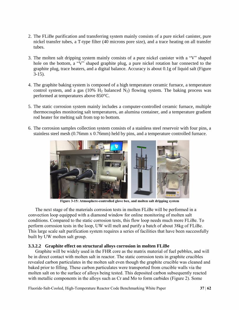
Fluoride-Salt-Cooled, High-Temperature Reactor Code Benchmarking White Paper 37 | 62
2. The FLiBe purification and transferring system mainly consists of a pure nickel canister, pure
nickel transfer tubes, a T-type filter (40 microns pore size), and a trace heating on all transfer
tubes.
3. The molten salt dripping system mainly consists of a pure nickel canister with a “V” shaped
hole on the bottom, a “V” shaped graphite plug, a pure nickel rotation bar connected to the
graphite plug, trace heaters, and a digital balance. Accuracy is about 0.1g of liquid salt (Figure
3-15).
4. The graphite baking system is composed of a high temperature ceramic furnace, a temperature
control system, and a gas (10% H2 balanced N2) flowing system. The baking process was
performed at temperatures above 850°C.
5. The static corrosion system mainly includes a computer-controlled ceramic furnace, multiple
thermocouples monitoring salt temperatures, an alumina container, and a temperature gradient
rod heater for melting salt from top to bottom.
6. The corrosion samples collection system consists of a stainless steel reservoir with four pins, a
stainless steel mesh (0.76mm x 0.76mm) held by pins, and a temperature controlled furnace.
Figure 3-15: Atmosphere-controlled glove box, and molten salt dripping system
The next stage of the materials corrosion tests in molten FLiBe will be performed in a
convection loop equipped with a diamond window for online monitoring of molten salt
conditions. Compared to the static corrosion tests, this flow loop needs much more FLiBe. To
perform corrosion tests in the loop, UW will melt and purify a batch of about 38kg of FLiBe.
This large scale salt purification system requires a series of facilities that have been successfully
built by UW molten salt group.
3.3.2.2 Graphite effect on structural alloys corrosion in molten FLiBe
Graphite will be widely used in the FHR core as the matrix material of fuel pebbles, and will
be in direct contact with molten salt in reactor. The static corrosion tests in graphite crucibles
revealed carbon particulates in the molten salt even though the graphite crucible was cleaned and
baked prior to filling. These carbon particulates were transported from crucible walls via the
molten salt on to the surface of alloys being tested. This deposited carbon subsequently reacted
with metallic components in the alloys such as Cr and Mo to form carbides (Figure 2). Some

Fluoride-Salt-Cooled, High-Temperature Reactor Code Benchmarking White Paper 38 | 62
carbon also diffused into the bulk alloy to form to form carbide phases, such as Cr3C2, Cr7C3,
Cr23C6, Mo2C, and Al4C3, in the near-surface regions of the alloy. In the 3000 hour corrosion
tests of 316 stainless steel in molten FLiBe in the graphite crucible at 700°C, the carbide-
containing layer extended deeper than 50 microns. This carbide layer seemed to stabilize Cr in
the alloys. However, the carbides might influence other properties of alloys in the molten salt.
For example, the hardness and thermal conductivity of the alloys’ surface layer changes due to
the formation of carbides on and in the alloys. During the MSRE program, carburization was
found in the Hastelloy N that was in intimate contact with graphite parts, but it was not
considered to be a concern because a sacrificial shim was placed between the graphite and
metal[22]. Is it reasonable to neglect this issue for the FHR? Or is it necessary to investigate the
carburization phenomenon?
Figure 3-16: Surface and cross-sectional SEM images of Hastelloy N tested in molten FLiBe in graphite crucible at 700°C
for 1000 hours.
3.3.2.3 Microstructural evolution during corrosion in molten FLiBe
Since the corrosion of alloys in molten salts takes place at high temperatures (700°C for the
FHR), the microstructure of the alloys can evolve. This microstructural evolution during
corrosion increases the complexity of the corrosion rate evaluation. It is therefore important to
separate the thermal effects from molten salt effects on the final corrosion results to fully
understand the corrosion behavior of alloys in molten fluoride salt. Although the microstructural
instability of alloys at high temperature has been investigated [23, 24, 25], it is a challenge to
quantify each factor on the final corrosion because both effects occur simultaneously.
3.3.2.4 Model development for predicting corrosion attack
It is desirable to develop a model for predicting corrosion attack of alloys in molten fluoride
salt. As previously mentioned, corrosion tests in high temperature molten fluorides is challenging
work. Running long-term corrosion tests not only requires durable and reliable facilities, but are
also costly. Under the assumption of thermal diffusion controlled corrosion[26], [27], UW
developed a simplified model to calculate the maximum Cr depletion distance which was
selected as a criterion to evaluate the corrosion attack depth. The calculated overall Cr depletion
profiles reasonably fit experimental results. However, to precisely model the corrosion of alloys
in high temperature molten fluoride salts, many factors must be considered. For example, in most
alloys, the grain boundary diffusion (Dgb) predominantly contributes to the overall diffusion
coefficient (Deff) [28], [29]. It is not well-known how the grain boundary precipitate changes the
Cr diffusion through the grain boundary during high temperature corrosion in molten salt.

Fluoride-Salt-Cooled, High-Temperature Reactor Code Benchmarking White Paper 39 | 62
3.3.2.5 Redox potential measurements of molten FLiBe
A compact electrochemical probe (
Figure 3-17) has been developed to measure the redox potential in flibe via an in-situ
dynamic beryllium electrode as described by Afonichkin et al[30]. The dynamic reference
electrode removes the need for the ion permeable container used in typical electrochemical cells,
creating a simpler, more robust probe, which has the potential to operate in varying depths. This
probe is capable of operating on a loop, or static system at salt temperatures exceeding 500 ̊C.
Only robust materials proven to be inert are in contact with the salt. The probe has been well-
characterized in Li2BeF4 salt over wide variety operating conditions, yielding redox
measurements with an accuracy of ±4 mV.
Figure 3-17: UW beryllium reduction probe cutaway drawing
Table 3-5. Part List of UW Probe Design
Part Description
1 Vitreous Carbon Anode
2 Molybdenum Electrodes
3 PTFE Ferrule
4 ¼” Swagelok Fittings
5 Boron Nitride Spacer
6 Viton O-Ring
A measurement begins by applying a voltage to a submerged cathode, creating a current
between the molybdenum cathode and submerged glassy carbon anode, forcing beryllium
fluoride to reduce as beryllium at the cathode. After sufficient plating, the circuit is opened,
allowing beryllium to donate electrons to the salt, reforming beryllium fluoride. As the beryllium
recombines, it creates a distinct voltage on the cathode which can be referenced and compared to
the potential on a third, submerged molybdenum indicator electrode, yielding the redox potential.
After the beryllium reference reaction diminishes, the potential between the cathode and
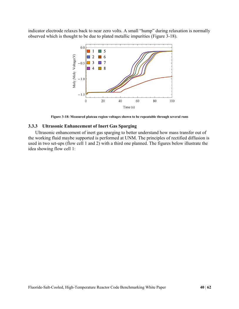
Fluoride-Salt-Cooled, High-Temperature Reactor Code Benchmarking White Paper 40 | 62
indicator electrode relaxes back to near zero volts. A small “hump” during relaxation is normally
observed which is thought to be due to plated metallic impurities (Figure 3-18).
Figure 3-18: Measured plateau region voltages shown to be repeatable through several runs
3.3.3 Ultrasonic Enhancement of Inert Gas Sparging
Ultrasonic enhancement of inert gas sparging to better understand how mass transfer out of
the working fluid maybe supported is performed at UNM. The principles of rectified diffusion is
used in two set-ups (flow cell 1 and 2) with a third one planned. The figures below illustrate the
idea showing flow cell 1:
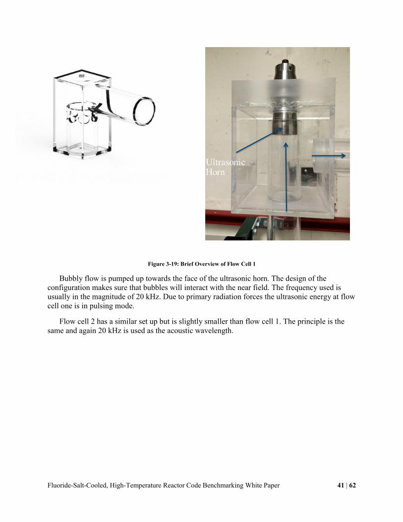
Fluoride-Salt-Cooled, High-Temperature Reactor Code Benchmarking White Paper 41 | 62
Figure 3-19: Brief Overview of Flow Cell 1
Bubbly flow is pumped up towards the face of the ultrasonic horn. The design of the
configuration makes sure that bubbles will interact with the near field. The frequency used is
usually in the magnitude of 20 kHz. Due to primary radiation forces the ultrasonic energy at flow
cell one is in pulsing mode.
Flow cell 2 has a similar set up but is slightly smaller than flow cell 1. The principle is the
same and again 20 kHz is used as the acoustic wavelength.

Fluoride-Salt-Cooled, High-Temperature Reactor Code Benchmarking White Paper 42 | 62
Figure 3-20: Brief Overview of Flow Cell 2
Preliminary results optical results using a high speed camera show potential improvement in
the sparging mass transfer. See pictures below.
Figure 3-21: First Results of the High Speed Camera

Fluoride-Salt-Cooled, High-Temperature Reactor Code Benchmarking White Paper 43 | 62
However, a need for more accurate design has been identified to account for the bubble to
bubble radiation or secondary Bjerkens forces.
3.3.4 System Models of Materials Chemistry, Activation, Tritium and Transport (MATT)
MIT (J. Stempien) as part of its first IRP has developed a model of TRITium Diffusion EvolutioN
and Transport (TRIDENT) with benchmarking using existing experimental data. TRIDENT integrates
the effects of the tritium production, chemical redox potential, tritium mass transfer, tritium diffusion
through pipe walls, and selective Cr attack by tritium fluoride. Systems for capturing tritium from the
coolant were proposed and simulated with TRIDENT. The capabilities of this system model relative
to other models is summarized below.
Comparison of TRIDENT features critical for FHR analysis with features of other codes.
TRIDENT TMAP4/7 ORNL-
4575 TPAC
ORNL-
TM-4804
SFR/FUS-
TPC THYTAN
Time-
dependence X X X X X
T
Transport X X X X X X
T
production
model in flibe
X
Other T
production
(ternary fission
etc.)
User must
define X X X
Reactor
system-level
model
X User may
build X X X X
Reactor
Coolants flibe/flinak
flibe/He/
Pb/Pb-Li flibe He Flibe
Na/Pb-
Li He
Redox
Dependence X X X
Isotope
Exchange X X X X X
Corrosion
Reactions X X
Corrosion
Product Mass
Transport
X X
Model of
T sorption on
graphite
X X
Online
pebble refueling
effects
X
T
permeator
system model
X
T removal
to purge gas X
User may
define X X
Counter-
current gas
stripping
X
Secondary
loop model X X X X

Fluoride-Salt-Cooled, High-Temperature Reactor Code Benchmarking White Paper 44 | 62
3.3.5 Planned corrosion research at Georgia Tech
Project related facilities include multiple furnaces for molten salt experiments (up to
1000°C). Tests can be carried out under inert gas atmosphere. A glove box with controlled
atmosphere will be used glove box to prepare salts and prepare samples for tests.
Other related facilities in our group include electrochemical equipment like potentiostats, and
Electrochemical Impedance equipment. Thermal balance for high temperature oxidation studies
under gaseous environments. Access to surface characterization methods including SEM, EDS,
XPS etc.
Three types of tests are planned in our group at Georgia Tech:
Corrosion under static conditions in pure FLiNaK
Exposure tests will be conducted at 700°C and 850°C in graphite crucibles with Ar
cover gas.
Commercial Ni-based alloys (including Hastelloy-N, Hastelloy-X, Hastelloy-B,
Haynes-230, Inconel-617, Inconel 625, Incoloy-800H, Inconel 625, and Ni-201) and
austenitic stainless steel grades 304L, 316L, 347, and 321. Pure metals Ni, Fe, Cr,
Mo, and Mn.
Results will be compared to those of FLiNaK exposure tests done at the UW and
other groups as well as tests done in MS loop at ORNL.
Impurity and redox condition effects on corrosion behavior of selected alloys:
Levels of impurities such as excess fluoride, oxides, HF, or excess reactive metal (Zr)
will be systematically controlled and their effects investigated using electrochemical
measurements during exposure tests.
Commercial Ni-based alloys (including Hastelloy-N, Hastelloy-X, Hastelloy-B,
Haynes-230, Inconel-617, Inconel 625, Incoloy-800H, Inconel 625, and Ni-201) and
austenitic stainless steel grades 304L, 316L, 347, and 321. Pure metals Ni, Fe, Cr,
Mo, and Mn.
Initially a pseudo reference electrode (Mo) will be used. Work will also develop and
use Ni based reference electrodes for molten salts.
Effect of Flow on Corrosion in Molten Salts
Flow rate effects will be investigated using the rotating electrode method. The
rotating sample will spin at different speeds to simulate different flow rates. These
tests will be done at different temperatures and different time periods.
Five alloys with the best corrosion behavior based on the results of other experiments
will be tested.

Fluoride-Salt-Cooled, High-Temperature Reactor Code Benchmarking White Paper 45 | 62
Results will be compared with ORNL loop test results as well as with the static tests
done at Georgia Tech.
3.3.6 Relevant material research capabilities at Ohio State University
Glove box Systems Equipped with Electrochemical Cell and Gamry Potentiostat:
To ensure accurate results, it must be ensured the experiments are conducted within an inert
environment. This is accomplished by conducting the experiment within a glove box. In using a
glove box, the environment will be in an inert Argon gas with sensors to ensure minimal H2O
and O2 contamination. Therefore, all the tests related to molten salt will be conducted in glove
box system. Recently, the PI’s molten salt Lab at OSU has designed and fabricated two glove
box systems, and the two systems will be in operation in Mar.2015.
The first glove box system is from Innovative Technologies, and is a custom glove box. This
glove box box has an internal working dimension of 96’’ x 65’’ x 31’’ (width x height x depth).
The glove box will be placed on a small stand to allow the ideal height for testing. The glove
box has eight gloves to work from that are configured in, 2 rows of four. When on the stand, the
bottom row of gloves are at standing height (48 inches above the ground) to allow for work on
the floor of the glove box, and the upper gloves (at 72 inches from the ground) are to work on the
adjustable shelves for material storage. It was determined that the lower gloves could be used
when operating the furnace by standing on the ground. The upper gloves can be used to perform
material preparation by standing on a small platform that could be set on the ground. This
extended height is ideal because it allows longer electrodes to come from the furnace, enough
space to work above the furnace, and enough room left over to store materials.
The second glove box is also from the same company, but a standard box, Innovative
Technologies PureLab 1950. This glove box has an internal working dimension of 76 x 35 x 31
(inches for Width x Height x Diameter). The glove box has four gloves to work from with
adjustable shelves for material storage. This glove box will also include a well on the glove box.
This well is added to allow a furnace to sit within for testing. By adding a well, the top of the
furnace, where most of the manipulation is done for the experiment is at glove level. This is to
allow more room above the furnace to allow more room for the removing the samples. The well
can also be closed when making preparations to materials to allow for the full range of the inside
floor spacing.
Both of glove box systems come with a gas purification
system to recirculate argon gas and a heat exchanger to moderate
temperature within the box. It contains filters with enough
absorption capacity for 30 liters of O2 and 1300 grams of H2O
and sensors to measure the content between 0 – 1000 ppm for
both impurities to ensure the correct conditions are met when
testing. These sensors are viewed and controlled via a touch
screen interface. It also has antechambers to allow materials to
be transferred into the glove box while the environment is
maintained.
Figure 3-22: Modulated Speed
Rotator

Fluoride-Salt-Cooled, High-Temperature Reactor Code Benchmarking White Paper 46 | 62
Both glove box systems are equipped with custom designed electrochemical cells for conduct
molten salt-related experiments. In the cells, the temperature can research as high as 750°C.
Modulated Speed Rotator
The lab also equipped with 3 modulated speed rotators which can be applied control the
working electrode rotating speed, then to identify the flow effects on the materials corrosion. The
rotation rate of the electrode may be read from the LCD display on the front panel, and the rate
may be adjusted using the knob located just below this display. The rotation rate is adjustable
over a range from 50 to 10,000 RPM and is accurate to within 1% of the reading on the display.
A voltage output signal that is proportional to the rotation rate is available on the front panel.
This signal may be used to monitor the rotation rate using an external voltmeter or data
acquisition system.
ThermoCalc Software
The PI’s lab has ThermoCalc software license. ThermoCalc is a software based on
CALPHAD (CALculation of PHAse Diagrams) approach to calculate the multicomponent
thermodynamics and phase diagrams. It has two main components: the internally-consistent
thermodynamic databases, and application itself, which determine the range and properties of a
multi-component system that can be calculated. Current, the software has many databases
including databases for molten salt, stainless steel, Ni-base alloys, Zr-base alloys and aqueous
solutions which will benefit our proposed research. In addition, the capabilities of ThermoCalc
may be extended by adding your own databases or retrieving the multicomponent
thermodynamic data and phase equilibrium results through the software development kits, such
as the TQ-Interface, TC-API, and TC-Toolbox for MATLAB, and combing them with your own
application programs.
Materials Characterization Tools
The Institute of Materials Research (IMR) of the university has a range of scanning and
electron microscopes for performing fracture surface analysis, chemical analysis (SEM/EDX),
X-ray diffraction, electron backscattered diffraction (EBSD), and conventional transmission
electron microscopy (TEM), and facilities for fabricating bulk and thin film characterization
samples.
3.3.7 Relevant material research opportunities at ORNL
As needed, the Corrosion Science and Technology Group has access to personnel and
facilities housed within the ORNL’s Materials Science and Technology Division (MSTD), which
is a large, diversified materials research division with over 300 employees. The division consists
of 19 research groups encompassing 6 major technical themes: theory and modeling at multiple
scales; designed synthesis of structural alloys and ceramics, specialized crystals, and condensed
matter physics systems; structural characterization via electron, ion, photon, and neutron
sciences; comprehensive physical and mechanical property characterization; interactions with
extreme environments; and applied materials physics. The division also houses 3 program
offices and 2 major user facilities: the High Temperature Material Laboratory (HTML) and the
Shared Research Equipment (SHaRE) User Facility and Program. These facilities offer world-
class capability for the manufacture, processing, characterization and evaluation of the physical,

Fluoride-Salt-Cooled, High-Temperature Reactor Code Benchmarking White Paper 47 | 62
mechanical, thermal, and environmental properties of materials and are available to the proposed
research program.
An extensive array of arc-casting and related metals processing facilities are available to
manufacture model alloys for this study including casting, hot rolling, cold rolling, heat
treatment/quenching, and machining capabilities such as electoral discharge machining. For
characterization of mechanical properties, numerous high-temperature electromechanical, servo-
hydraulic, and lever-arm dead load machines are available to conduct creep and creep fatigue
testing. Several machines were upgraded to allow testing in corrosive environments such as
steam and molten salt. For evaluating surface reaction and rate limiting reactions, MSTD houses
electrochemical test systems, high-temperature autoclaves, inert glove boxes, and an array of
welding tools including electron beam that ensure controlled environment and allow for creating
specialized test articles. MSTD also houses x-ray diffractomers and an array of optical and
electron microscopes for the evaluation of surface morphology, surface micro-chemistry, and
crystallinity of surface products. In addition, there is access to neutron diffraction, if needed.
Characterization equipment that may be employed include 6 state-of-the-art scanning and
transmission electron microscopes (STEM/TEM) with aberration-correction, EELS, EFTEM,
EDS, electron holography, HRTEM, and HAADF capabilities. Three field emission gun
scanning electron microscopes with BSE, OIM/EBSD, and EDS capabilities, electron probe
microanalysis (EPMA), and XPS and Auger electron spectroscopy including in-situ fracture
capability to study failure surfaces are available. Atom probe tomography (APT) for 3D atomic
scale resolution of precipitate chemistry is also available.
3.4 FHR Benchmark Data Management: NE-KAMS
Advanced modeling and simulation (M&S) for nuclear energy development involves
significant processing and use of digital data. To assess the reliability of M&S results,
computational and experimental data are needed for V&V. To estimate error limits of
computational and experimental outcomes, a considerable amount of data must be processed for
UQ. To ensure successful nuclear M&S development:
significant data and related information from diverse sources of computations and
experiments must be efficiently managed and correctly used with great accuracy and
consistency;
communications between modelers and experimentalists must be conducted on a
mutually understood base;
information and knowledge generated must be adequately preserved for future reference;
and
unnecessary research and development (R&D) redundancies must be readily identified
and eliminated for cost- and time-efficiency.
It is apparent that the immensity and diversity of data involved in advanced nuclear M&S
poses a great challenge to satisfying these needs and requirements.
Fluoride-Salt-Cooled, High-Temperature Reactor Code Benchmarking White Paper 48 | 62
To rise to the challenge, it was proposed that a multi-faceted knowledge management system
is needed to support V&V and UQ of M&S for nuclear energy development. Such a system must
provide a comprehensive and web-accessible knowledge base with V&V and UQ expertise and
resources for establishing confidence in the use of M&S for nuclear reactor design, analysis, and
licensing. It should offer support to development and implementation of standards, requirements
and best practice for V&V and UQ that enable scientists and engineers to assess the quality of
their M&S while facilitating access to computational and experimental data for physics
exploration. It should also serve as a platform for technical exchange and collaboration, enabling
credible computational models and simulations for nuclear energy applications. Furthermore, it
must be able to assist positioning programs of the Department of Energy (DOE) to share the
costs associated with development and application of M&S, capture and preserve the V&V, UQ
and M&S knowledge and data, and provide value-added tools and utilities while leveraging its
knowledge-sharing ability to educate young scientists and engineers in government, industry,
and academia.
The concept of such a multi-faceted knowledge management system has attracted great
interest and gained strong support from stakeholders across industry, academia, and government
for the development of NE-KAMS. Nevertheless, the cost and time required for the development
became a serious issue, as it became obvious that an advanced, sophisticated, and robust system
that could meet these high requirements would demand significant resources and years of
development time. Due to the pressing needs of several DOE M&S projects and increasingly
strained budgets, initiation of such a development seemed funds- and time- prohibitive, unless an
existing “launching pad” could be found.
An extensive search was conducted by the Nuclear Energy Advanced Modeling and
Simulation (NEAMS) Program to identify potential candidates. After thorough scrutiny and
evaluations, it was concluded that the relational database infrastructure at ORNL established
through the Gen IV Materials Handbook Project could best meet the requirements. The
Handbook has been used by DOE for data collaboration among nine signatories representing
more than ten countries involved in Generation IV Nuclear Reactor development since 2009, and
its infrastructure has provided a solid foundation for the spinoffs of the Nuclear System Materials
Handbook Database, the Nuclear Concrete Materials Database, the ASME Materials Database,
and several other smaller databases. The infrastructure that has evolved, along with the expertise
and experience accumulated through these projects, can enabled rapid development and
implementation of major features and functionalities that are highly desired for NE-KAMS,
which include 1) high traceability of complicated relations between data; 2) robust but flexible
access control applicable to every level of data hierarchy in a database to meet information
control requirements of different projects; 3) versatile reorganization of large quantities of digital
data in various desired formats; 4) efficient data transfer between data storage and computational
models; and of pragmatic importance, 5) the capability to become operational in less than six
months.
Development of NE-KAMS officially started in mid-June 2012 with a collaboration among
Idaho National Laboratory (INL), Bettis Atomic Power Laboratory (BAPL), Argonne National
Laboratory (ANL), Sandia National Laboratories (SNL), and ORNL. As the development
continues, more collaborators are expected to join in the project [31].

Fluoride-Salt-Cooled, High-Temperature Reactor Code Benchmarking White Paper 49 | 62
The FHR IRP-2 proposes to use the NE-KAMS database as the project’s data management
system. The benefits of controlling the data management through NE-KAMS is the ability to
access all experimental data from anywhere, to compare data from different experiments directly,
and to store all experimental data securely.

Fluoride-Salt-Cooled, High-Temperature Reactor Code Benchmarking White Paper 50 | 62
4 Candidate Benchmarking Exercises
The purpose of the candidate benchmarking exercises in the three subject areas serve several
purposes, including to begin defining the scope of phenomena that are possible to explore
through benchmarking, which phenomena are most desirable to explore, and how the exercises
should begin and then progress throughout the span of the project.
4.1 Neutronics Candidate Benchmarking Exercises
IAEA (IAEA-TECDOC-1694) and OECD/NEA IRPhE HTGR benchmarks provide helpful
guidelines for setting up benchmarks and experimental campaigns, but overall they are not fully
relevant for near term FHR neutronic benchmarking efforts. Three stages of code-to-code
comparison may be used for neutronics benchmarking in IRP-2. The code-to-code comparison
may consist of three phases, with the detailed down selection of problems being performed by
the neutronics working group later:
1. Code capabilities check
The purpose of this phase is to test code capabilities and quantify discrepancies on simple
test problems. Because the nearest-term neutronic test data for FHRs is expected to be provided
by the SINAP TMSR-SF1 test reactor, which will use pebble fuel, pebble geometries will also be
the primary initial focus for IRP-2 neutronics benchmarking. Two models will be used: (1) unit
cell with reflective boundary conditions comprising one pebble and corresponding coolant
volume, with low-enriched uranium and no fission products; (2) horizontal cross section (infinite
long) of the TMSR-SF1 that includes an active core region and reflector (this is similar to what
was done by IAEA for gas cooled reactors, but replace cubic model with infinite cylindrical
model).
Calculations to be performed (all conditions are fixed in the benchmark definition) for both
models will provide reactivity (infinite multiplication factor), average flux, average neutron
spectrum, radial leakage (for the cylindrical model only), and power distribution in the following
conditions:
a. Fully homogenized fuel/coolant+
b. Heterogeneous coolant/pebble, homogeneous inner pebble (mixing pebble shell,
matrix and TRISO)+
c. Fully resolved double heterogeneity+
d. Ordinate bed+
e. Random bed+
2. Criticality and reactivity worth tests
These benchmark problems will assess mostly criticality and reactivity worth for first core
using a TMSR-SF1 fuel core 3D model (this ideally would be a completion of the 2D model
used in phase 1) with uniform conditions (zero power, uniform temperature):

Fluoride-Salt-Cooled, High-Temperature Reactor Code Benchmarking White Paper 51 | 62
a. Number of pebbles required to achieve criticality for a fixed enrichment+
b. Enrichment necessary to reach criticality for a fixed bed+
c. Coolant temperature reactivity worth+
d. Fuel temperature reactivity worth+
e. Graphite (matrix and shell) reactivity worth+
f. Control system reactivity worth+
g. Single (or cluster) pebble reactivity worth (space dependent) *
Besides reactivity, these tests should also provide power distribution and flux spatial (and
energy) distribution in selected locations in the core and in the reflector to emulate actual or
potential sensor locations. All these evaluations should be repeated at full power and cold
shutdown conditions.
3. Dynamic tests
This phase will include time dependent evaluations, such as:
a. Burnup with fixed bed+
b. Burnup with once-through bed*
c. Burnup with continuous refueling*
d. Transients (RIA, LOFA, others?)*
Computationally, these evaluations (excluding a) could be quite complex; therefore better
gauge of the existing modeling capabilities during phase 1 and 2, and before making a final
decision needs to be considered.
4.2 Thermal Hydraulics Candidate Benchmarking Exercises
The key thermal hydraulic phenomena that have been identified in previous FHR work that
are important to address in benchmarking exercises include natural circulation, including passive
decay heat removal; heat transfer in high Pr coolants, including enhanced heat transfer surfaces
such as pebble beds and twisted tubes; heat/flow distributions in critical components such as
bypass flow in the reactor; heat exchanger performance; conduction in the fuel and the reactor
structures; and radiation heat transfer in molten salts. These phenomena are meant to bound the
thermal hydraulics space that this IRP can perform benchmarking exercises within. The exercises
that are actually performed over the course of the project will be down-selected from this space
based on the importance of the phenomena, the quality of the data available, current knowledge
gaps, and licensing concerns. The down-selection to a realistic set of benchmarking exercises
will be a critical process, and will be one of the initial steps taken by the thermal hydraulics
working group.
The ability to identify key phenomena for a given technology is necessary for defining the
scope of benchmarking activities. The proposed method is through the use of phenomena
identification and ranking tables (PIRTs), which are an element of the EMDAP which comes
from NRC Regulation Guide 1.203. During the development of the practical set of benchmarking
exercises, it may be necessary to supplement the PIRT process with a more limiting evaluation

Fluoride-Salt-Cooled, High-Temperature Reactor Code Benchmarking White Paper 52 | 62
method that takes into account existing validation data sets, operating experimental facilities, and
the resources of IRP-2.
The first exercise posed during the workshop discussions is meant to be an example of an
initial problem that can be chosen during the beginning of IRP-2 because of its study of
fundamental FHR thermal hydraulic phenomena and the knowledge gap it represents.
Candidate exercise one (CE1) explores steady-state natural circulation flow in a loop. The
purpose is to validate the relevant performance models against experimental data for validation.
This is a critical first step before more advanced models/scenarios can be explored. This exercise
is able to be performed on many experimental facilities, including CIET 1.0, the UNM Heat
Transfer Loop, thermal hydraulic loops developed at UW, the OSU DRACS test loops, the
Liquid Salt Test Loop at ORNL, and the thermal hydraulic loops at SINAP. The ability to
perform CE1 on several test facilities and validate several models should lead to very accurate
and flexible natural circulation models. It is important to note that this is a relatively
straightforward test to perform in isolation (without coordinated benchmarking with other
universities or partners), and there may already be work underway or work completed that can be
included in this effort.
Candidate exercise two (CE2) is meant to represent a mature benchmarking exercise that
should be performed towards the end of the project after more fundamental areas are fully
explored and essential knowledge gaps have been filled. CE2 is a transient response, time-at-
temperature study for loss-of-forced-circulation (LOFC) transients, both with and without scram
(ATWS). The purpose is to determine the time the system remains above a certain temperature
threshold during a LOFC transient in the FHR, both with or without a full scram occurring. The
significance will be the ability to address the LBE initiating event, “decrease in reactor coolant
system flow rate,” and that the data can be used to address the limiting safety cases of structural
integrity during transients. The experimental facility used in this exercise is the CIET facility
(UCB) and the figures of merit include the peak bulk coolant outlet temperature, the time at
temperature for metallic and ceramic structures, the temperature difference across the DRACS,
and the time to establishment of natural circulation.
SETs are an important part of benchmarking as they directly support the IETs by exploring
individual phenomena in isolation. This allows IETs to test how different thermal hydraulic
phenomena interact in a system. Examples of SETs would be tests to provide pressure drop
correlations and heat transfer coefficients for integral test facilities. An example of a SET would
be the exploration the bi-directional shell –side heat transfer in the DHX with buoyancy effects
using both plain and twisted tube geometries within the DHX. The purpose of this exercise is to
address the lack of data for buoyant flows in twisted tubes. The bi-directional flow component
data is necessary because of the flow reversal present in the DHX. Data can be provided for a
range of Re and Pr which will give heat transfer correlations for several different candidate salts
over a range of operating conditions. CE1 will use the DHX Heat Transfer Loop at UNM, and
the figures of merit are heat transfer enhancement due to twisted-tubes and the effect on heat
transfer due to local buoyancy forces for up- and down-flow (degrading/enhancing).
The ability to instrument SETs extensively to generate high-quality data for loss coefficients,
and component characterization and other system characteristics and state parameters, will be
important as system characteristics such as loss coefficients represent the majority of uncertainty.

Fluoride-Salt-Cooled, High-Temperature Reactor Code Benchmarking White Paper 53 | 62
Comparison of uncertainty from different sources be valuable, particularly in developing future
PIRTs for FHRs.
In general, there will be serious scrutiny on the scaling practices applied to justify using
simulant fluids in the place of molten salt. Therefore verifying the similitude between the
selected simulant fluids and the working salts will be critical in establishing the application of
scaled experiments for validation of FHR evaluation models, particularly for licensing purposes.
A good method of proving similitude will be to use diverse data from multiple experimental
facilities using both oil and salt, or data compared to multiple evaluation models. An important
aspect in data diversity is that the characterization of uncertainty will be different. If a diverse
data set can be used to validate a diverse set of evaluation models to a high degree of
acceptability by licensing bodies, this will be a significant step towards understanding and
applying molten salts in reactor systems.

Fluoride-Salt-Cooled, High-Temperature Reactor Code Benchmarking White Paper 54 | 62
4.3 Materials Corrosion, Activation, Tritium, and Transport (MATT)
Candidate Benchmarking Exercises
Materials corrosion, materials and coolant activation, tritium behavior and transport of
tritium and corrosion products in an FHR are tightly coupled as shown in Fig. 4-1 for the
TRIDENT code to model these effects that was described earlier.
Figure 4-1: TRIDENT Model of Materials, Tritium, and Corrosion Behavior in the FHR
Neutron radiation of fluoride salts containing lithium and or beryllium generate tritium
fluoride (3HF). The salt redox potential then determines how much is remains as TF and how
much is converted into T2. The TF can cause metallic corrosion in the FHR heat exchangers and
particularly the selective corrosion of chromium from the metal. The T2 can diffuse through
metals and determines tritium release rates. Carbon in the fuel absorbs both TF and T2 but its
absorption capacity is limited. As a consequence tritium generation, metal (chromium) corrosion
and deposition rates around the loop as a function of temperature, transport of tritium and
corrosion products by the salt, tritium removal in different chemical forms, tritium inventory, and
tritium releases to the environment are tightly coupled and cannot be separately modeled.
TRIDENT addresses all of these phenomena. At the current time the lack of good experimental
data, particularly integrated tests, is a major limitation. Benchmarking is to address this
challenge by finding new sources of data, refine models where required, and enable long-term
predictions of system behavior.
Of particular interest for material benchmarking is material- and more specifically tritium
mass transport in FHRs. Three a scales:
1) Fuel: Chemical interactions based upon temperature, neutron damage, graphite
properties, FLiBe saturation, reactive species ratios (ex: [T2]/[TF]), and mass transfer
characteristics.
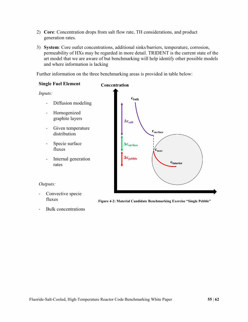
Fluoride-Salt-Cooled, High-Temperature Reactor Code Benchmarking White Paper 55 | 62
2) Core: Concentration drops from salt flow rate, TH considerations, and product
generation rates.
3) System: Core outlet concentrations, additional sinks/barriers, temperature, corrosion,
permeability of HXs may be regarded in more detail. TRIDENT is the current state of the
art model that we are aware of but benchmarking will help identify other possible models
and where information is lacking
Further information on the three benchmarking areas is provided in table below:
Single Fuel Element
Inputs:
- Diffusion modeling
- Homogenized
graphite layers
- Given temperature
distribution
- Specie surface
fluxes
- Internal generation
rates
Outputs:
- Convective specie
fluxes
- Bulk concentrations
Figure 4-2: Material Candidate Benchmarking Exercise “Single Pebble”

Fluoride-Salt-Cooled, High-Temperature Reactor Code Benchmarking White Paper 56 | 62
FHR Core
Inputs:
- Temperature and
flow distributions
- Bulk generation
rates
Outputs:
- Core outlet
concentrations
- Core concentration
drop
Figure 4-3: Material Candidate Benchmarking Exercise “Pebble Bed Core”
FHR Loop
Inputs:
- Concentration
additions/drops
through loop
- Permeation rates
- Corrosion rates
Outputs:
- Tritium release
fraction
- Product
distributions
Figure 4-4: Material Candidate Benchmarking Exercise “Loop”

Fluoride-Salt-Cooled, High-Temperature Reactor Code Benchmarking White Paper 57 | 62
5 Proposed Path Forward
Overall, the most critical outcome of the first IRP-2 workshop is to define the path forward to
continue FHR research and development efforts under the new DOE IRPs. This includes how to
divide and coordinate research between IRP partner universities and how to structure future
workshops.
5.1 Technical Area Working Groups
Three clear technical areas emerged during workshop preparation and discussions:
neutronics; thermal hydraulics; and materials corrosion, activation, tritium and transport
(MATT). These three technical areas create a clear division of FHR phenomena that encompass
the most important phenomena required for FHR licensing and commercial development. Based
on recommendations from the workshop participants on the division of FHR phenomena into
these three technical areas, the IRPs propose to form three working groups to organize future
research efforts within the broader FHR benchmarking campaign.
Each working group will consist of students and professors from FHR IRP partner
universities with related interests in the technical area of the working group as well as
universities and organizations that fall outside the formal IRP organization. Additionally, each
working group will have its own advisory committee consisting of professors, national
laboratory scientists, and other technical area experts to help guide research efforts. Beyond
providing guidance, the oversight of an expert advisory committee will help facilitate
collaboration and mentorship between established experts within the Nuclear Engineering field
and students in Nuclear Engineering, ensuring a high degree of knowledge transfer and
continuation of FHR development capability. Developing an advisory committee will be one of
the first tasks for each working group. However, identifying working group chairs to run and
hold accountable sub-groups is a necessary first-step before technical efforts can be coordinated.
Charters for the working groups can then be developed, designating responsibilities and powers
the groups have.
The flexibility of having the FHR evaluation model benchmarking efforts divided among
three technical area working groups also allows for more contact and collaboration through
video-conferencing, side meetings at conferences related to the working groups’ technical area,
and other more frequent interactions. This will be critical for maintaining communication and
progress within working groups in between the larger FHR benchmarking workshops, which are
proposed to meet approximately annually.

Fluoride-Salt-Cooled, High-Temperature Reactor Code Benchmarking White Paper 58 | 62
The IRP partner universities, including the GT-led IRP, are tentatively divided into working
groups as follows2:
Neutronics: UCB, GT, MIT
Thermal Hydraulics: UCB, OSU, UNM, UW
Materials Corrosion, Activation, Tritium, and Transport: UW, MIT, GT, OSU
Each working group will identify two lead faculty members who will co-chair the group. The
responsibilities of the lead faculty will include: developing a working group charter,
communication and coordination within the working group as well as with the other working
groups, organization of working group resources, prioritization of benchmarking efforts,
coordination and integration of the working group advisory committee, and other managerial
duties. Working group co-chairs may be faculty from either IRP.
During the beginning of the combined IRP efforts, the working groups will primarily work
separately as their technical areas are relatively disparate. However, sharing individual
experiences with benchmarking efforts with the other working groups will be critical in further
development of benchmarking best practices and creating positive communication practices.
Also, as the understanding of FHR phenomena advances during the course of the IRPs, the more
complex phenomena will require coupled development between working groups, e.g. thermal
hydraulics – neutronics coupling to understand complex FHR transient behaviors that will be
important for licensing efforts. Sub-working groups may be necessary to facilitate this cross-
working group collaboration, and will be explored further during subsequent workshops as
benchmarking efforts advance.
In practice, benchmarking activities within each working group will include participation
from organizations outside of the IRP partner universities both domestically and internationally.
Outside collaboration will serve several purposes, primarily: (1) providing additional credibility
to benchmarking campaign results as more diverse experimental data, model predictions, and
applications of FHR phenomena are contributed by additional benchmarking participants; (2)
providing high-quality experience to students through their collaboration with professionals and
experts in the Nuclear Engineering field on a reactor design and development project of
significant depth and breadth; and (3) acquiring international attention and interest in the
advancement of FHR technology development.
5.2 Future Workshop Organization
Future MIT-led IRP benchmarking workshops are proposed to have two complimentary
components: (1) a full IRP discussion component where all participants involved in FHR IRP
research efforts and contributing experts can meet to discuss topics pertinent to the IRPs at large,
and (2) separate breakout sessions consisting of working group members and their respective
2 Texas A&M University has an established and impressive expertise in instrumentation and control, and as such
does not readily fall into the proposed working group structure. TAMU’s role in this benchmarking campaign has
yet to be established, and they may contribute to FHR technology development and understanding in other, equally
important ways.

Fluoride-Salt-Cooled, High-Temperature Reactor Code Benchmarking White Paper 59 | 62
advisory committees to discuss topics pertinent to only the respective working group in more
detail. This workshop structure is a much more efficient use of participants’ time while still
encouraging collaboration and enthusiasm for FHR research within and outside the IRPs.
The proposed agenda for future MIT-IRP benchmarking workshops is a half-day of welcome
activities to allow all participants to arrive, a day dedicated to breakout sessions to discuss more
specific topics within the working groups, followed by a second day dedicated to general IRP
discussion.
The following tentative schedule for MIT-IRP benchmarking workshops is suggested:
Second FHR Benchmarking Workshop
o Date: April 13-15, 2016 (preceding the ICAPP meeting
April 17-20 in San Francisco)
o Location: UC Berkeley/San Francisco
Third FHR Benchmarking Workshop
o Date: February, 2017
o Location: TBD
Fourth FHR Benchmarking Workshop
o Date: October, 2017
o Location: TBD
The proposed dates for holding the subsequent three workshops are approximately based on
the proposed MIT-IRP milestone schedule, but ideally can be coordinated with other large events
to facilitate maximum participation. The date and location for the second FHR benchmarking
workshop is chosen to directly precede the ICAPP 2016 conference in San Francisco.
SINAP/ORNL combined meetings on the ORNL campus are also ideal for coordinating the
IRPs’ workshops as many of the key contributors will be present and ORNL has excellent
facilities to host an FHR workshop. Each workshop may also consider hosting an ANS 20.1
FHR Safety Standard Meeting the day before the workshop.
The GT-IRP is also planning to hold workshops focused on performing V&V and PIRT-like
activities for each of the three technical areas. The first neutronics workshop will be held at
Georgia Tech on December 7-10, 2015. These workshops will be complimentary to the
benchmarking focused workshops organized by the MIT-IRP, and there will be participation
from both IRPs in both sets of workshops.

Fluoride-Salt-Cooled, High-Temperature Reactor Code Benchmarking White Paper 60 | 62
6 References
[1] C. W. Forsberg, “Molten-salt-cooled advanced high-temperature reactor for production of
hydrogen and electricity,” Nucl. Technol., vol. 144, pp. 289–302, 2003.
[2] U.S. Nuclear Regulatory Commission, “Regulatory Guide 1.203: Transient and Accident
Analysis Methods,” 2005.
[3] IAEA, Evaluation of High Temperature Gas Cooled Reactor Performance - Benchmark
Analysis Related to the PBMR-400, PBMM, GT-MHR, HTR-10 and the ASTRA Critical
Facility - TECDOC-1694. VIENNA: IAEA, 2013.
[4] Oak Ridge National Laboratory, “Consortium for Advanced Simulation of Light Water
Reactors CASL Achievements and Plans CASL Strategic Goals CASL Mission
Achievements to Date Key Goals for 2 nd Five-Year Term,” Oak Ridge, 2010.
[5] A. T. Godfrey, “VERA-CS Validation Plan,” Oak Ridge National Laboratory, CASL-U-
2014-0185-000, Oak Ridge, Tennessee, 2014.
[6] K. J. Connolly, F. Rahnema, and P. V. Tsvetkov, Prismatic VHTR neutronic benchmark
problems, vol. 285. Elsevier B.V., 2015.
[7] H. Joo, T. a Taiwo, and W. S. Yang, “Vhtr Numerical Benchmark Based on the Compact
Nuclear Power Source Experiments,” Nucl. Appl., 2007.
[8] T. a. Taiwo, T. K. Kim, W. S. Yang, H. S. Khalil, W. K. Terry, J. Blair Briggs, and D. W.
Nigg, “Evaluation of High Temperature Gas-Cooled Reactor Physics Experiments as
VHTR Benchmark Problems,” 2005.
[9] R. O. Scarlat, M. R. Laufer, E. D. Blandford, N. Zweibaum, D. L. Krumwiede, A. T.
Cisneros, C. Andreades, C. W. Forsberg, E. Greenspan, L. W. Hu, and P. F. Peterson,
“Design and licensing strategies for the fluoride-salt-cooled, high-temperature reactor
(FHR) technology,” Prog. Nucl. Energy, vol. 77, pp. 406–420, 2014.
[10] N. Zweibaum, G. Cao, A. T. Cisneros, B. Kelleher, M. R. Laufer, R. O. Scarlat, J. E.
Seifried, M. H. Anderson, C. W. Forsberg, E. Greenspan, L. W. Hu, P. F. Peterson, and K.
Sridharan, “Phenomenology, methods and experimental program for fluoride-salt-cooled,
high-temperature reactors (FHRs),” Prog. Nucl. Energy, vol. 77, pp. 390–405, 2014.
[11] Idaho National Laboratory, “Guidance for Developing Principal Design Criteria for
Advanced ( Non-Light Water ) Reactors,” Idaho Falls, 2014.
[12] “MIT Nuclear Reactor Laboratory,” 2014. .

Fluoride-Salt-Cooled, High-Temperature Reactor Code Benchmarking White Paper 61 | 62
[13] K. Sun, M. Ames, T. Newton, and L. Hu, “Validation of a fuel management code
MCODE-FM against fission product poisoning and flux wire measurements of the MIT
reactor,” Prog. Nucl. Energy, vol. 75, pp. 42–48, Aug. 2014.
[14] M. Laufer and G. Buster, “X-Ray Pebble Recirculation Experiment ( X-PREX ) Design
and Initial Experimental Results,” Berkeley, California, 2015.
[15] N. Zweibaum, L. Huddar, J. T. Hughes, M. R. Laufer, E. D. Blandford, R. O. Scarlat, and
P. F. Peterson, “Role and Status of Scaled Experiments in the Development of Fluoride-
Salt-Cooled, High-Temperature Reactors,” in International Congress on Advances in
Nuclear Power Plants, 2015.
[16] Q. Lv, X. Wang, I. H. Kim, X. Sun, R. N. Christensen, T. E. Blue, G. Yoder, D. Wilson,
and P. Sabharwall, “Scaling Analysis for the Direct Reactor Auxiliary Cooling System for
FHRs,” Nucl. Eng. Des., no. 285, pp. 197–206, 2015.
[17] Q. Lv, H. C. Lin, I. H. Kim, X. Sun, R. N. Christensen, T. E. Blue, G. Yoder, D. Wilson,
and P. Sabharwall, “DRACS Thermal Performance Evaluation for FHR,” Ann. Nucl.
Energy, no. 77, pp. 115–128, 2015.
[18] Q. Lv, M. Chen, I. H. Kim, X. Sun, R. N. Christensen, T. E. Blue, G. Yoder, D. Wilson,
and P. Sabharwall, “Design of Fluidic Diode for a High-Temperature DRACS Test
Facility,” in The 21st Interntional Conference on Nuclear Engineering (ICONE21), 2013.
[19] G. Yoder, “Liquid Salt Test Loop,” Oak Ridge, Tennessee, 2015.
[20] G. Zheng, B. Kelleher, G. Cao, K. Sridharan, M. Anderson, and T. R. Allen,
“Investigation of 2LiF-BeF2 (FLiBe): Salt Transfer, Corrosion Tests and
Characterization,” in Transactions of 2013 American Nuclear Society Winter Meeting,
2013.
[21] B. Kelleher, G. Zheng, M. Anderson, K. Sridharan, and G. Cao, “Purification of Non
Uranium Bearing Fluoride Salts for Nuclear Applications,” in Transactions of the
American Nuclear Society, 2013, vol. 109, no. 1971, pp. 1079–1081.
[22] H. E. McCoy and J. R. Weir, “Materials Development for Molten-Salt Breeder Reactors,
ORNL-TM-1854,” 1967.
[23] R. E. Gehlbach and H. E. McCoy, “Phase instability in Hastelloy N,” pp. 346–366 in
International Symposium on Structural Stability in Superalloys, Seven Springs, Pa. Sept.
1968, Vol. II.
[24] S. Downey, P. N. Kalu, and K. Han, “The effect of heat treatment on the microstructure
stability of modified 316LN stainless steel,” Mater. Sci. Eng. A, vol. 480, no. 1–2, pp. 96–
100, May 2008.

Fluoride-Salt-Cooled, High-Temperature Reactor Code Benchmarking White Paper 62 | 62
[25] S. M. Schlegel, S. Hopkins, and M. Frary, “Effect of grain boundary engineering on
microstructural stability during annealing,” Scr. Mater., vol. 61, pp. 88–91, 2009.
[26] R. B. Evans, J. H. DeVan, and G. M. Watson, “Self-diffusion of chromium in nickel-base
alloys, ORNL-2982,” 1961.
[27] J. H. DeVan and R. B. Evans, “Corrosion behavior of reactor materials in fluoride salt
mixtures, ORNL-TM-0328,” 1962.
[28] Y. F. Yin and R. G. Faulkner, “Model predictions of grain boundary chromium depletion
in Inconel 690,” Corros. Sci., vol. 49, pp. 2177–2197, 2007.
[29] T.-F. Chen, G. P. Tiwari, Y. Iijima, and K. Yamauchi, “Volume and Grain Boundary
Diffusion of Chromium in Ni-Base Ni-Cr-Fe Alloys.,” Mater. Trans., vol. 44, no. 1, pp.
40–46, 2003.
[30] V. K. Afonichkin, A. L. Bovet, V. V. Ignatiev, A. V. Panov, V. G. Subbotin, A. I.
Surenkov, A. D. Toropov, and A. L. Zherebtsov, “Dynamic reference electrode for
investigation of fluoride melts containing beryllium difluoride,” J. Fluor. Chem., vol. 130,
no. 1, pp. 83–88, Jan. 2009.
[31] W. Ren, Nuclear Energy Knowledge Base for Advanced Modeling and Simulation -
Functionalities and Operation ( Beta ) – NE-KAMS Version Beta –. Oak Ridge,
Tennessee, 2012.