FGRWirelessDataTransceivers - crsllc-pa.comcrsllc-pa.com/Manuals/FGR User Manual and Reference...
115
Part Number: LUM0047AA Revision: B Last Updated: 09/25/2012 FGR Wireless Data Transceivers FGRO9-CA / FGRO9-CSU / FGRO9-TSU FGRSR-CSU / FGRSR-TSU FGR-115RC / FGR-115WC Covering Firmware 2.69 User Manual and Reference Guide
Transcript of FGRWirelessDataTransceivers - crsllc-pa.comcrsllc-pa.com/Manuals/FGR User Manual and Reference...

Part Number: LUM0047AARevision: BLast Updated: 09/25/2012
FGR Wireless Data TransceiversFGRO9-CA / FGRO9-CSU / FGRO9-TSU
FGRSR-CSU / FGRSR-TSUFGR-115RC / FGR-115WCCovering Firmware 2.69
User Manual and Reference Guide
Safety InformationThe products described in this manual can fail in a variety of modes due to misuse, age, or malfunction. Systemswith these products must be designed to prevent personal injury and property damage during product operationand in the event of product failure.
Warning! Do not remove or insert diagnostics cable while circuit is live unless the area isknown to be free of ignition concentrations of flammable gases or vapors.
WarrantyFreeWave Technologies, Inc. warrants your FreeWave® Wireless Data Transceiver against defects in materials andmanufacturing for a period of two years from the date of shipment. In the event of a Product failure due to materialsor workmanship, FreeWave will, at its option, repair or replace the Product. The Product must be returned toFreeWave upon receiving a Return Material Authorization (RMA) for evaluation of Warranty Coverage.
In no event will FreeWave Technologies, Inc., its suppliers, and its licensors be liable for any damages arising fromthe use of or inability to use this Product. This includes business interruption, loss of business information, or otherloss which may arise from the use of this Product. Please be advised that OEM customer’s warranty periods mayvary.
Warranty Policy may not apply:
1. If Product repair, adjustments or parts replacements is required due to accident, neglect, unusualphysical, electrical or electromagnetic stress.
2. If Product is used outside of FreeWave specifications.
3. If Product has been modified, repaired, or altered by Customer unless FreeWave specificallyauthorized such alterations in each instance in writing. This includes the addition of conformal coating.
Special Rate Replacement OptionA special rate replacement option is offered to non-warranty returns or upgrades. The option to purchase thereplacement unit at this special rate is only valid for that RMA. The special replacement rate option expires if notexercised within 30 days of final disposition of RMA.
Restricted RightsAny product names mentioned in this manual may be trademarks or registered trademarks of their respectivecompanies and are hereby acknowledged. Information in this manual is subject to change without notice and isproprietary and confidential to FreeWave Technologies, Inc.
This manual is for use by purchasers and other authorized users of FreeWave® transceivers.
No part of this manual may be reproduced or transmitted in any form or by any means, electronic or mechanical, orfor any purpose without the express written permission of FreeWave Technologies, Inc. FreeWave reserves theright to make changes to this manual without notice. Unless otherwise agreed to in writing, FreeWave assumes noresponsibility or liability for the use of this manual or the infringement of any copyright or other proprietaryright. FreeWave shall deem nothing contained in this manual as warranty or guarantee.
FreeWave's Wireless Data Transceivers are designed and manufactured in the United States of America.
FreeWave Technologies, Inc.1800 South Flatiron Court
Boulder, CO 80301303.381.9200
Toll Free: 1.866.923.6168Printed in the United States of America. Fax: 303.786.9948Copyright © 2012 by FreeWave Technologies, Inc. All rights reserved. www.freewave.com
LUM0047AA Rev B ii
This product is licensed by The United States. Diversion contrary to U.S. law is prohibited. Export or re-exportof this product outside of The United States may require authorization by the U.S. Bureau of Industry andSecurity. Please contact FreeWave Technologies, Inc. for assistance and further information.
UL NotificationsModels FGRO9-CSU, FGRO9-TSU, and FGRSR-CSU are suitable for use in Class 1, Division 2, Groups A, B, C,and D or non-hazardous locations only. Do not connect or disconnect any connectors while the circuit is live unlessthe area is known to be non-hazardous.
Note: Models FGRO9-CA, FGRSR-TSU, FGR-115RC, and FGR-115WC are not UL approved.
Warning! EXPLOSION HAZARD - SUBSTITUTION OF COMPONENTS MAY IMPAIRSUITABILITY FOR CLASS 1, DIVISION 2.
Warning! DO NOT REMOVE OR INSERT THE DIAGNOSTICS CABLE WHILE THECIRCUIT IS LIVE UNLESS THE AREA IS KNOWN TO BE FREE OF IGNITIONCONCENTRATIONS OR FLAMMABLE GASES AND VAPORS.
Input voltage for models FGRO-9CA, FGRO9-CSU, FGRO9-TSU, FGR-115RC, and FGR-115WC is +6.5 to +30VDC. Input voltage for models FGRSR-CSU and FGRSR-TSU is +6.0 to +20.0 VDC.
Important: Input power shall be derived from a single Class 2 power source.
LUM0047AA Rev B iii

FCC NotificationsThis device complies with part 15 of the FCC rules. Operation is subject to the following two conditions: 1) Thisdevice may not cause harmful interference and 2) this device must accept any interference received, includinginterference that may cause undesired operation.
This device must be operated as supplied by FreeWave Technologies, Inc. Any changes or modifications made tothe device without the express written approval of FreeWave Technologies, Inc. may void the user's authority tooperate the device.
Warning! The model number FGR09 has a maximum transmitted output power of 955 mW.It is recommended that the transmit antenna be kept at least 23 cm away from nearbypersons to satisfy FCC RF exposure requirements.
Whenever any FreeWave Technologies, Inc. module is placed inside an enclosure, a label must be placed on theoutside of the enclosure. The label must include the text "Contains: FCC ID" (with the module's FCC ID number).
IC NotificationsThis device complies with Industry Canada licence-exempt RSS standard(s). Operation is subject to the followingtwo conditions: (1) this device may not cause interference, and (2) this device must accept any interference,including interference that may cause undesired operation of the device.
Ce dispositif est conforme aux normes permis-exemptes du Canada RSS d'industrie. L'opération est sujette auxdeux conditions suivantes : (1) ce dispositif peut ne pas causer l'interférence, et (2) ce dispositif doit acceptern'importe quelle interférence, y compris l'interférence qui peut causer le fonctionnement peu désiré du dispositif.
LUM0047AA Rev B iv

Document Revision History
Date Rev Letter Updates Made
09/25/2012 B The reference to AES encryption in "FGRO9-CA, FGRO9-CSU, andFGRO9-TSU Transceiver Specifications" on page 84 has been removed.AES encryption is not and has not ever been an option in the FGRmodels.
04/26/2012 A This document replaces theSpread SpectrumWireless Data TransceiverUser Manual v6.3 and now covers only FGR radios. IM Series radios aredocumented in the IMWireless Data Transceivers User Manual andReferenceGuide.
The following content has been added:
l Examples of how to use subnet IDs to route communication throughyour network on page 46.
l Working with parallel repeaters on page 65.l Troubleshooting information starting on page 73.In addition, the organization of the document has been updated to addresscontent that applies to all networks, content that applies toMultiPointnetworks, and content that applies to Point-to-Point networks. Refer tothe Table of Contents.
LUM0047AA Rev B v

LUM0047AA Rev B vi
Table Of Contents
Preface xi
Chapter 1: Introduction 1
Choosing a Location for the Transceivers 1
Choosing Point-to-Point or Point-to-MultiPoint Operation 2
Data Communication Link Examples 3
Finding the Product Serial Number 5
Mounting Notes 6
Powering the Transceiver 6
Configuration Tool Options 7
Tool Suite and Terminal Emulators 8
Transceiver SetupMode 8
Using Tool Suite to Connect to and Program Transceivers 9
Accessing the SetupMenu Using a Terminal Emulator 10
Connecting and Disconnecting from HyperTerminal 15
Troubleshooting HyperTerminal 15
Upgrading Transceivers to the Latest Firmware 17
Chapter 2: Basic Transceiver Programming and Setup 19
Setting the Transceiver's Role in the Network and the Network Type 19
Establishing Communication with Instrumentation and Computers 21
Baud Rate 22
Data Parity 22
Flow Control 22
Modbus RTU 23
Serial Interface 23
Setup Port 24
Turn Off Delay 25
Turn OnDelay 25
Use Break to Access Setup 25
Establishing Communication with Other Transceivers in the Network 26
"Golden Settings" 26
Setting RF Transmission Characteristics 27
Frequency Key (Golden Setting) 27
Frequency Zones 28
High Noise 30
LUM0047AA Rev B vii
Hop Table Size 31
Hop Table Version 31
Max Packet Size andMin Packet Size (Golden Setting) 32
MCU Speed 34
Remote LED 34
Retry TimeOut 35
RF Data Rate (Golden Setting) 35
RTS to CTS 36
Slave Security 37
Transmit Power 37
Transmit Rate 38
Chapter 3: Configuring Point-to-MultiPoint Networks 39
Point-to-MultiPoint Network Characteristics 40
Golden Settings 40
Master-to-Slave Communication 40
Slave-to-Master Communication 40
Point-to-MultiPoint Network Quick Start 40
Point-to-MultiPoint Operation LEDs 43
OverlappingMultiPoint Networks 43
Establishing Communication with Other Transceivers in aMultiPoint Network 43
Using the Network ID inMultiPoint Networks 44
Using the Call Book inMultiPoint Networks 44
Programming Point-to-MultiPoint Extended Call Book 45
Routing Communication Through the Network 45
Assigning Subnet ID Values 46
Setting Other MultiPoint Parameters 48
1 PPS Enable Delay 48
Diagnostics 49
DTR Connect 50
Local Mode 50
Master Packet Repeat 50
Master Packet Repeat in MultiPoint Networks with Repeaters 51
Max Slave Retry 51
Radio ID 52
Radio Name 52
Repeater Frequency 52
LUM0047AA Rev B viii

Repeaters 53
Retry Odds 53
Slave/Repeater 54
Conserving Power 54
Low PowerMode 54
Reading Diagnostics in Tool Suite 56
Chapter 4: Configuring Point-to-Point Networks 59
Point-to-Point Network Quick Start 59
Point-to-Point Operation LEDs 62
Using the Call Book in Point-to-Point Networks 62
Programming Point-To-Point Extended Call Book to Use Three or Four Repeaters 64
Chapter 5: Advanced Programming 65
Working with Parallel Repeaters 65
Setting Transceiver Passwords 67
Low Baud Rates 68
Multi-Master Synch 68
TimeDivisible Multiple Access (TDMA) 68
Chapter 6: Viewing Radio Statistics 69
Antenna Reflected Power 69
Master-Slave Distance 70
Noise Level 70
Number of Disconnects 70
Radio Temperature 70
Rate% 70
Signal Level 71
Transmit Current 71
Chapter 7: Troubleshooting 73
Troubleshooting Flowchart 74
Troubleshooting 75
Chapter 8: Additional Transceiver Information 79
Operational RS422 and RS485 Information 79
RS422 and RS485 Full Duplex Pin-Outs 80
RS485 Half Duplex Pin-Outs 80
RS232 Pin Assignments (DB-9) 80
RF Board Level Pinout 81
FGR-115WC Waterproof Enclosure Pinout for Cable ASC0613WW 82
LUM0047AA Rev B ix
FGRO9-CA, FGRO9-CSU, and FGRO9-TSU Transceiver Specifications 84
FGRSR-CSU and FGRSR-TSU Transceiver Specifications 86
FGR-115RC and FGR-115WC Transceiver Specifications 88
Factory Default Settings 90
FGR OEM Full Size Board Level Drawing 91
OEMMini-Board Level Mechanical Drawing 92
Appendix A: Firmware Updates 93
Index 97
LUM0047AA Rev B x

LUM0047AA Rev B
Preface
This document includes the following regarding the FreeWave FGR transceivers:
l A basic introduction to the transceiver and how to determine themode you want to run it in.
l Examples of how FreeWave transceivers can exist in a network with other transceivers.
l How to access the setup parameters available on the transceiver.
l Basic transceiver programming and setup information that applies to all network types.
l Considerations and quick starts for your network design, including charts of LED displays.
l Details about defining aMultiPoint network including the use of subnet IDs to route informationthrough the network.
l Steps to view statistics about a transceiver's performance.
l Pin out andmechanical drawings.
For information about the firmware releases that apply to the transceiver, see Appendix A.
The contents of this document assumes that you have a basic understanding of Tool Suite and itscomponents. For more information about using Tool Suite, see the Tool Suite User Manual available on theUserManual and System Tools CD or by selecting File > Help in the Tool Suite software.
Notational ConventionsThis guide uses the following notational conventions:
l Bold - Indicates items that you select, parameter settings, and parameter names.
l Warning! - Indicates a situation that might cause damage to your radio, data, or network.
l - Provides time saving or informative suggestions about using the product.
xi

Preface
LUM0047AA Rev B
The term "radio" and "transceiver" are used throughout this manual to refer to the FGR radios.
Contacting FreeWave Technical SupportFor up-to-date troubleshooting information, check the Support page at www.freewave.com.
FreeWave provides technical support Monday through Friday, 7:30 AM to 5:30 PMMountain Time (GMT -7).Call toll-free at 1.866.923.6168, within Colorado call 303.381.9200, or contact us through email [email protected].
Documentation FeedbackYour feedback is important to us! FreeWave Technologies, Inc. is committed to continually improving thequality of our documentation. If you have any comments or suggestions about this document, send them to usat [email protected]. Please include the title of the document or the document's part number in youremail.
Additional InformationThis guide covers settings and configurations that apply to FreeWave spread spectrum transceivers. Sometransceiver models have specific settings and configurations that apply to only that model. For informationabout a specific model or additional information about using the radios in your network, see the addendumsand application notes listed below.
l FGR RadioModem inMirrored Bit Mode User Manual Addendum
l Application note #5412: Synchronizing CollocatedMasters (Multi-Master Sync Mode)
l Application note #5476:Mode 6
l Application note #5424: Using the FGR-115MB Radio with Schweitzer Engineering Labs MirroredBits Communications
l Application note: #5437: DTR to CTS Line Alarm Feature
l Application note #5457: Local Mode
For information about installing your transceivers, see the 900MHz Wireless Transceiver Installation Guide.
All FreeWave documentation is available on theUserManual and System Tools CD and atwww.freewave.com.
xii
LUM0047AA Rev B
Chapter 1: Introduction
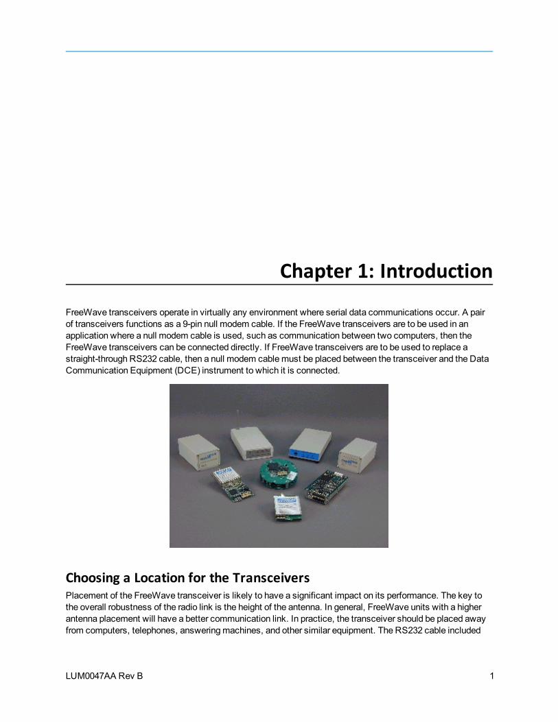
FreeWave transceivers operate in virtually any environment where serial data communications occur. A pairof transceivers functions as a 9-pin null modem cable. If the FreeWave transceivers are to be used in anapplication where a null modem cable is used, such as communication between two computers, then theFreeWave transceivers can be connected directly. If FreeWave transceivers are to be used to replace astraight-through RS232 cable, then a null modem cablemust be placed between the transceiver and the DataCommunication Equipment (DCE) instrument to which it is connected.
Choosing a Location for the TransceiversPlacement of the FreeWave transceiver is likely to have a significant impact on its performance. The key tothe overall robustness of the radio link is the height of the antenna. In general, FreeWave units with a higherantenna placement will have a better communication link. In practice, the transceiver should be placed awayfrom computers, telephones, answeringmachines, and other similar equipment. The RS232 cable included
1

Chapter 1: Introduction
LUM0047AA Rev B
with the transceiver usually provides ample distance for placement away from other equipment. FreeWaveTechnologies, Inc. offers directional andOmni directional antennas with cable lengths ranging from 3 to 200feet. When using an external antenna, placement of that antenna is critical to a solid data link. Other antennasin close proximity are a potential source of interference; use the Radio Statistics to help identify potentialproblems.
The Show Radio Statistics page is found in option 4 in themain terminal menu or in the Diagnostic informationin Tool Suite. An adjustment as little as 2 feet in antenna placement can resolve some noise problems. Inextreme cases, such as when interference is due to a Pager or Cellular Telephone tower, the band pass filtersthat FreeWave offers, may reduce this out-of-band noise.
FreeWave also offers a waterproof version of the 900MHz transceivers. This model can be placed outdoorswithout additional weather protection. The waterproof enclosure requires an external antenna and includes a 6-foot data and power pigtail cable.
Choosing Point-to-Point or Point-to-MultiPoint OperationA Point-to-Point network is best suited when your network consists of oneMaster and one Slave transceiver.You can add up to four Repeaters to extend the reach of the network.
Important: Adding a Repeater to a network cuts the network throughput by 50%.
In a Point-to-MultiPoint network (also referred to as MultiPoint network) theMaster transceiver is able tosimultaneously communicate with numerous Slaves. In its simplest form, aMultiPoint network functions withtheMaster broadcasting its messages to all Slaves. If requested by theMaster, the Slaves respond to theMaster when given data by the device connected to the data port. This response depends on your setup. Youcan extend the reach of the network with as many Repeaters as is required. As with Repeaters in a Point-to-Point network, adding Repeaters to a network cuts the throughput by half.
It is important to note the differences between Point-to-Point andMultiPoint networks. In a Point-to-Pointnetwork all packets are acknowledged, whether sent from theMaster to the Slave or from the Slave to theMaster. In aMultiPoint network, you determine the number of times outbound packets from theMaster orRepeater to Slaves or other Repeaters are sent. The receiving transceiver, Slave or Repeater, accepts thefirst packet received that passes the 32 bit CRC. However, the packet is not acknowledged. On the return tripto theMaster, all packets sent are acknowledged or retransmitted until they are acknowledged. Therefore, thereturn link in aMultiPoint network is generally very robust.
Traditionally, a MultiPoint network is used in applications where data is collected frommany instruments andreported back to one central site. The architecture of such a network is different from Point-to-Pointapplications. The following parameters influence the number of transceivers that can exist in aMultiPointnetwork:
1. Data block size. The longer the data blocks, the fewer number of deployed Slaves can exist in thenetwork.
2. Baud rate. The data rate between the transceiver and the device to which it is connected couldlimit the amount of data and the number of transceivers that can exist in a network
3. The amount of contention between Slaves. Polled Slaves vs. timed Slaves.
4. Repeater Use. Using theRepeater setting in a Point-to-Point or MultiPoint network decreasesoverall network capacity by 50%.
2
FGR Wireless Data Transceivers
LUM0047AA Rev B
For example, if the network polls Slaves once a day to retrieve sparse data, several hundred Slaves could beconfigured to a single Master. However, if each Slave transmits larger amounts of data or datamorefrequently, fewer Slaves can link to theMaster while receiving the same network performance. When largeramounts of data are sent more frequently, the overall network bandwidth is closer to capacity with fewerSlaves.
Data Communication Link ExamplesFreeWave transceivers' versatility allows data communication links to be established using a variety ofdifferent configurations.
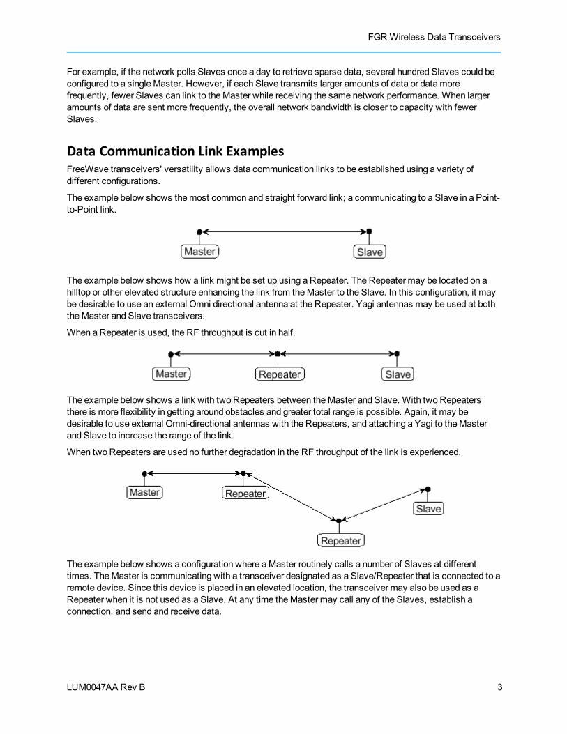
The example below shows themost common and straight forward link; a communicating to a Slave in a Point-to-Point link.
The example below shows how a link might be set up using a Repeater. The Repeater may be located on ahilltop or other elevated structure enhancing the link from theMaster to the Slave. In this configuration, it maybe desirable to use an external Omni directional antenna at the Repeater. Yagi antennas may be used at boththeMaster and Slave transceivers.
When a Repeater is used, the RF throughput is cut in half.
The example below shows a link with two Repeaters between theMaster and Slave. With two Repeatersthere is more flexibility in getting around obstacles and greater total range is possible. Again, it may bedesirable to use external Omni-directional antennas with the Repeaters, and attaching a Yagi to theMasterand Slave to increase the range of the link.
When two Repeaters are used no further degradation in the RF throughput of the link is experienced.
The example below shows a configuration where aMaster routinely calls a number of Slaves at differenttimes. TheMaster is communicating with a transceiver designated as a Slave/Repeater that is connected to aremote device. Since this device is placed in an elevated location, the transceiver may also be used as aRepeater when it is not used as a Slave. At any time theMaster may call any of the Slaves, establish aconnection, and send and receive data.
3

Chapter 1: Introduction
LUM0047AA Rev B
The next example illustrates a standard Point-to-MultiPoint network. From theMaster, any data is broadcastto all three Slaves, one of which receives it through aMultiPoint Repeater. The data is in turn sent out of theserial port of each of the three Slaves. The end device should be configured to interpret the serial messageand act on it if necessary.
The last example is a Point-to-MultiPoint network that uses one of the sites as a Slave/Repeater. Thisnetwork functions in the samemanner as a standardMultiPoint network with Repeaters. However, thenumber of radios may be reduced with the use of theMultiPoint Slave/Repeater feature.
4

FGR Wireless Data Transceivers
LUM0047AA Rev B
Finding the Product Serial NumberEach FreeWave transceiver is assigned a unique serial number. If you need to contact FreeWave TechnicalSupport, you will be asked for the serial number on the transceiver you are calling about.
The serial number is three digits, followed by a hyphen and four digits, for example 111-1111, and is printed onthe FreeWave label on the transceiver. The example below is for a GXMmodel; however, the serial numberinformation will be in the same location on different models.
On transceivers that are not in an enclosure, you can also find the serial number printed on a label on the back(the flat, smooth side) of the transceiver. This label is in larger print.
5
Chapter 1: Introduction
LUM0047AA Rev B
Mounting NotesMount the transceiver to the flat, stable surface usingmounting holes in the corners of the transceiver.FreeWave recommends aminimum stand-off height of ¼ inch. The followingmounting bracket solutions areavailable from FreeWave:
l Model number ONTWK-001
l Model number PMB-ENCL
Transceiver models sold under FCC ID KNY-6231812519 are to be installed professionally in NEMAenclosures.
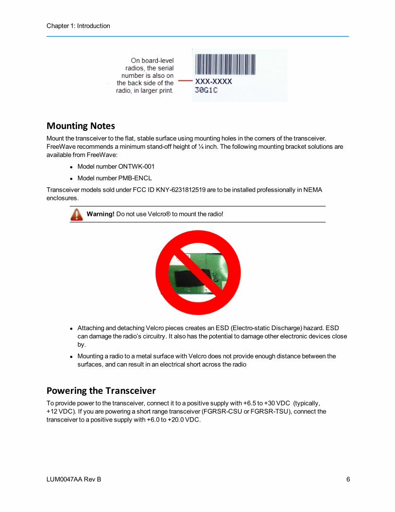
Warning! Do not use Velcro® tomount the radio!
l Attaching and detaching Velcro pieces creates an ESD (Electro-static Discharge) hazard. ESDcan damage the radio’s circuitry. It also has the potential to damage other electronic devices closeby.
l Mounting a radio to ametal surface with Velcro does not provide enough distance between thesurfaces, and can result in an electrical short across the radio
Powering the TransceiverTo provide power to the transceiver, connect it to a positive supply with +6.5 to +30 VDC (typically,+12 VDC). If you are powering a short range transceiver (FGRSR-CSU or FGRSR-TSU), connect thetransceiver to a positive supply with +6.0 to +20.0 VDC.
6
FGR Wireless Data Transceivers
LUM0047AA Rev B
Using a dedicated power supply line is preferred. The power supply you usemust providemore current thanthe amount of current drain listed in the specifications for the product and voltage you are using. For example,if you are using +12 VDC, the power supply must provide above the drain that is required for transmit as listedin the specifications.
Warning! If the power supply is above approximately +18.0 to +20.0 VDC, use a1 ohm resistor inline with B+ input to the radio. For more information about pinouts, see"RF Board Level Pinout" on page 81.
If the power supply line runs outside the radio enclosure, use electrostatic discharge (ESD) protectors toprotect the radio from electric shock, and transient voltage suppressors (TVS) to protect from an over-voltagesituation. Using both helps to ensure long-term, reliable operation. FreeWave does not supply these items;however, they can be purchased at most electronic supply stores.
Configuration Tool OptionsNote: The terms modem and transceiver are used interchangeably in this document
and in the text within the setup tools. While the words have different meanings,the two terms should be treated as one and the samewhen referring toFreeWave products.
When the transceiver is in Setupmode, you can use the following setup tools to configure the settings on thetransceiver:
l Tool Suite - Tool Suite is the newest configuration software and replaces EZConfig, and is therecommendedmethod for programming your transceivers.
It provides a group of tools for configuring the devices in your network and for monitoring yournetwork's performance. Using the Configuration application within Tool Suite, you can programchanges to your transceiver's settings. Tool Suite is available on theUserManual andSystem Tools CD and is also available for download from www.freewave.com.
For more information about using Tool Suite, see the Tool Suite User Manual available on theUserManual and System Tools CD or by selecting File > Help in the Tool Suite software.
l Terminal Emulator - A terminal emulator program, such as HyperTerminal or Tera Term, offersmany of the same configuration options that are available in the Configuration application in ToolSuite. Terminal emulators vary in cost, and several are downloadable free of charge. If you runversions of theWindows operating system prior toWindows 7, HyperTerminal is included in theoperating system installation. However, if you are runWindows 7 or newer, HyperTerminal is nolonger available.
You can use the terminal emulator program of your choice to program the transceiver. The SetupTerminal application within Tool Suite provides the same interface that is available using a terminalemulator.
You can also still use EZConfig to program your older transceiver models; however, Tool Suite is therecommended programming option. Newer transceiver models and newer firmware versions are not availablein EZConfig.
7

Chapter 1: Introduction
LUM0047AA Rev B
Tool Suite and Terminal EmulatorsIf you are using a terminal emulator, the tabs for a device in Tool Suite mirror the Setupmainmenu selections.For example, option 0 from the Setupmainmenu in the terminal menu setup is Set Operation Mode. Thecorresponding configuration tab for the device in Tool Suite is (0) Operation Mode.
You can also use the Setup Terminal application within Tool Suite to use and view theterminal menus. It displays the samemenus and provides the same programmingsettings as you see using a terminal emulator.
Throughout this document, if the setup procedure in the terminal emulator is different than the procedure inTool Suite, the terminal instructions are also included.
Transceiver Setup ModeTo read the current settings from or to program a transceiver, the transceiver must be in Setupmode. When atransceiver is in Setupmode, all three LEDs display solid green . See the sections below for detailsabout how to access the transceiver's Setupmode using Tool Suite or a terminal emulator.
Note: OEM boards may also enter Setup when Pin 2 is grounded, or using a breakcommand. For more information about the break command, see "Use Break toAccess Setup" on page 25.
TheSetup Port parameter in the Baud Rate tab determines whether themain data port or the diagnostics portis used to access the setup parameters for the transceiver. For more information, see "Setup Port" on page24.
Using theSetup Mode Timeout parameter in the OperationMode tab, you can set the transceiver to exitSetupMode automatically. When the setting is enabled, if the transceiver has not received any menuselections or programming information within 5 seconds, it exits Setup and resumes its previous mode.
8

FGR Wireless Data Transceivers
LUM0047AA Rev B
For Setupmode troubleshooting information, see "Troubleshooting " on page 73.
Using Tool Suite to Connect to and Program TransceiversTo read and program a transceiver using Tool Suite, you need to connect the transceiver to a computer thatruns the Tool Suite software. You can also use Tool Suite to set up a template version of a transceiver.Templates include settings that apply to more than one transceiver in your network. For more informationabout using templates, see the Tool Suite User Manual available from the File > Helpmenuwithin theapplication.
1. Connect a serial or diagnostic cable between the computer or laptop and the transceiver.
Using a diagnostic cable and the diagnostic port is recommended.
2. Connect the power supply to the transceiver and the power source and turn on the transceiver.
3. With the transceiver is connected to the computer in Tool Suite, click Configuration in theApplication pane to display the Configuration application.
4. Ensure the correct port is selected in theCom Port field in the Configuration ribbon.
5. Place the transceiver in Setupmode by pressing the Setup button on the back of the FreeWavetransceiver.
If you are connected to the diagnostics port, the transceiver changes to Setupmode automaticallywhen you click Read Radio in Tool Suite.
9
Chapter 1: Introduction
LUM0047AA Rev B
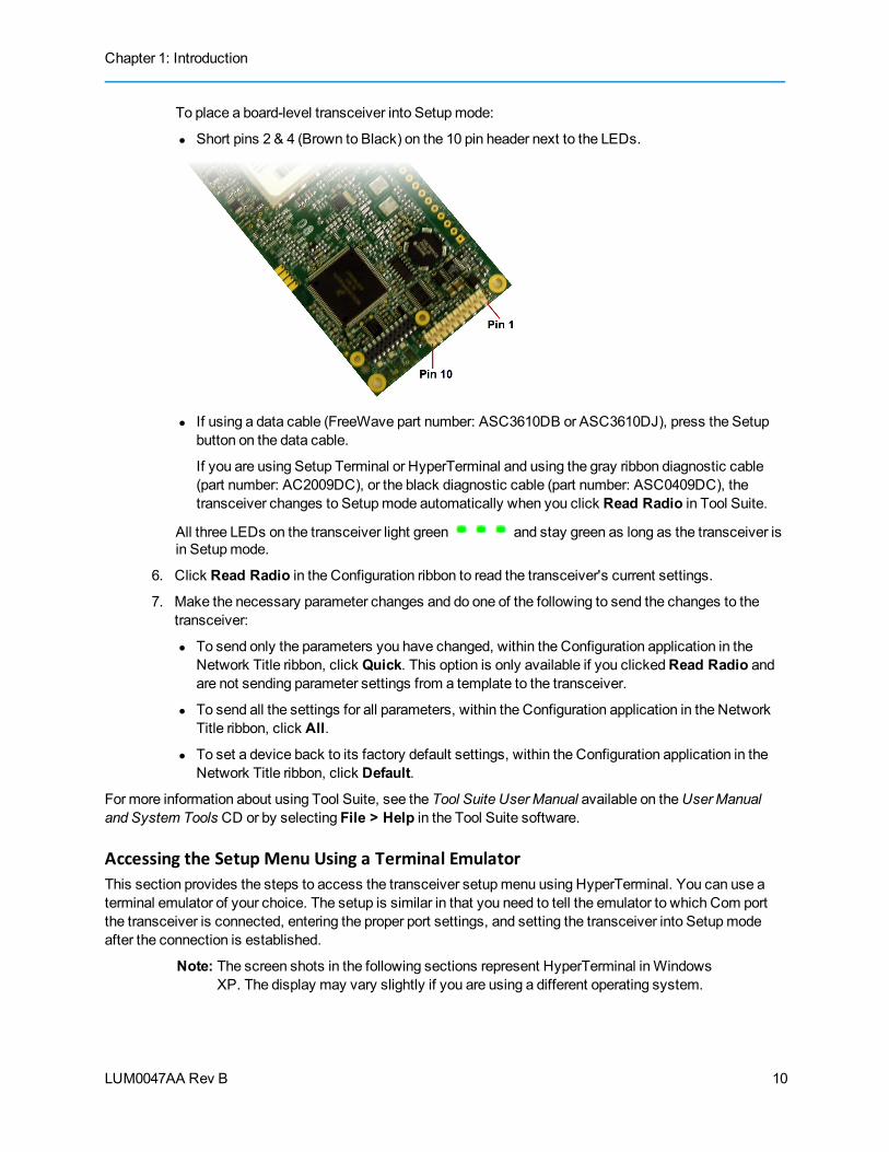
To place a board-level transceiver into Setupmode:
l Short pins 2 & 4 (Brown to Black) on the 10 pin header next to the LEDs.
l If using a data cable (FreeWave part number: ASC3610DB or ASC3610DJ), press the Setupbutton on the data cable.
If you are using Setup Terminal or HyperTerminal and using the gray ribbon diagnostic cable(part number: AC2009DC), or the black diagnostic cable (part number: ASC0409DC), thetransceiver changes to Setupmode automatically when you click Read Radio in Tool Suite.
All three LEDs on the transceiver light green and stay green as long as the transceiver isin Setupmode.
6. Click Read Radio in the Configuration ribbon to read the transceiver's current settings.
7. Make the necessary parameter changes and do one of the following to send the changes to thetransceiver:
l To send only the parameters you have changed, within the Configuration application in theNetwork Title ribbon, click Quick. This option is only available if you clickedRead Radio andare not sending parameter settings from a template to the transceiver.
l To send all the settings for all parameters, within the Configuration application in the NetworkTitle ribbon, click All.
l To set a device back to its factory default settings, within the Configuration application in theNetwork Title ribbon, click Default.
For more information about using Tool Suite, see the Tool Suite User Manual available on theUserManualand System Tools CD or by selecting File > Help in the Tool Suite software.
Accessing the Setup Menu Using a Terminal EmulatorThis section provides the steps to access the transceiver setupmenu using HyperTerminal. You can use aterminal emulator of your choice. The setup is similar in that you need to tell the emulator to which Com portthe transceiver is connected, entering the proper port settings, and setting the transceiver into Setupmodeafter the connection is established.
Note: The screen shots in the following sections represent HyperTerminal inWindowsXP. The display may vary slightly if you are using a different operating system.
10
FGR Wireless Data Transceivers
LUM0047AA Rev B
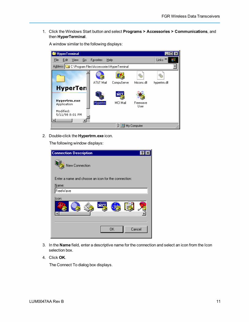
1. Click theWindows Start button and select Programs > Accessories > Communications, andthenHyperTerminal.
A window similar to the following displays:
2. Double-click theHypertrm.exe icon.
The following window displays:
3. In theName field, enter a descriptive name for the connection and select an icon from the Iconselection box.
4. Click OK.
The Connect To dialog box displays.
11
Chapter 1: Introduction
LUM0047AA Rev B
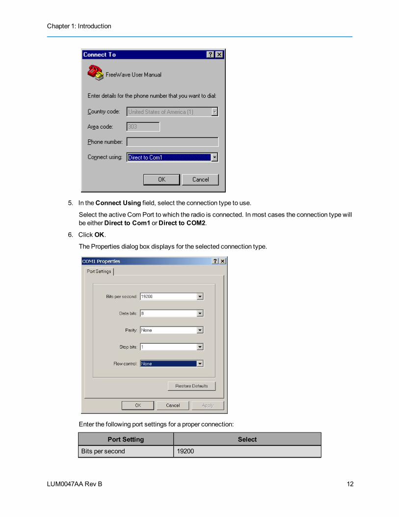
5. In theConnect Using field, select the connection type to use.
Select the active Com Port to which the radio is connected. In most cases the connection type willbe eitherDirect to Com1 orDirect to COM2.
6. Click OK.
The Properties dialog box displays for the selected connection type.
Enter the following port settings for a proper connection:
Port Setting Select
Bits per second 19200
12

FGR Wireless Data Transceivers
LUM0047AA Rev B
Port Setting Select
Data bits 8
Parity None
Stop bits 1
Flow control None
7. After selecting the option for each setting, click OK.
The following HyperTerminal dialog box displays:
8. From the Filemenu, select Save to save the HyperTerminal connection settings.
Important: Tomake changes to the connection properties, youmust first disconnectthe terminal session.
9. To connect HyperTerminal to the transceiver, press the Setup button on the back of the FreeWavetransceiver. If connected to the diagnostics port, typeU (Capital ‘U’) to invoke the Setupmenu.
13
Chapter 1: Introduction
LUM0047AA Rev B
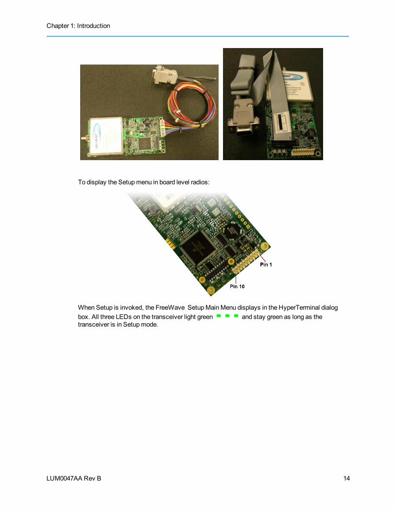
To display the Setupmenu in board level radios:
When Setup is invoked, the FreeWave SetupMainMenu displays in the HyperTerminal dialogbox. All three LEDs on the transceiver light green and stay green as long as thetransceiver is in Setupmode.
14

FGR Wireless Data Transceivers
LUM0047AA Rev B
As you navigate through the Setupmenu andmake changes to the parameters, the parameters aresent to the transceiver immediately.
Connecting and Disconnecting from HyperTerminalThe HyperTerminal dialog box displays several icons in the toolbar. To reconnect to HyperTerminal, you need
to disconnect your current session. Click theDisconnect icon, and then click theCall icon toreconnect. If the settings have not been saved they must be re-selected when HyperTerminal reconnects tothe transceiver.
Troubleshooting HyperTerminalThe following are some common issues encountered while using HyperTerminal.
Important:When a change is made to the HyperTerminal settings in an open terminalsessions, the connectionmust be disconnected then reconnected before the settingstake effect.
Nothing displays on the screen after placing the transceiver into Setup mode.
This usually indicates one of two things; either the wrong COM port is selected or a null modem cable is beingused. Follow the steps below to change the COM ports.
1. Click theDisconnect icon.
2. From the Filemenu, select Properties.
3. Click theConnect To tab and verify that the correct COM port is selected.
4. Click OK to close the Properties dialog box.
5. Click theCall icon.
6. Return the transceiver to Setupmode. The Setupmenu screen displays.
15

Chapter 1: Introduction
LUM0047AA Rev B
In addition, if the radio has been previously configured, you could be using the wrong port to access the Setupmenu. For more information, see "Setup Port" on page 24.Try connecting to the other port.
Gibberish displays on the screen after placing the transceiver into Setup mode.
This usually indicates a Baud Rate problem. Follow the steps below to change the Baud Rate. The problemmay also be that the transceiver under test is a TTL version or has been set to RS485 and not RS232. If theradio is TTL or in RS485mode, ensure that you are connected through the Diagnostic port. Gibberish beforethe Setup button is pressed indicates Diagnostics is enabled in aMaster.
1. Click theDisconnect icon.
2. From the Filemenu, select Properties.
3. Click Configure, change the following and click OK:
l Baud Rate to 19200
l Data Bits to 8
l Parity toNone
l Stop Bits to 1
l Flow Control to 1
4. Click OK to close the Properties dialog box.
5. Click theCall icon.
6. Return the transceiver to Setupmode. The Setupmenu screen displays.
The Setup menu displays on the screen, but nothing happens when keys on the keyboard arepressed.
This usually indicates flow control is turned on in a three-wire connection (Rx, Tx, andGnd). Follow the stepsbelow if the connection uses a three-wire connection.
1. Click theDisconnect icon.
2. From the Filemenu, select Properties.
3. Click Configure, change the Flow Control toNone, and click OK.
4. Click OK to close the Properties dialog box.
5. Click theCall icon.
6. Return the transceiver to Setupmode. The Setupmenu screen displays.
A connection exists, HyperTerminal is receiving data, and some data is correct, but the remainingdata is in unrecognizable characters.
This usually indicates a parity mismatch. To resolve this issue, ensure that the parity of the transceiver andthe parity of HyperTerminal are set the same. HyperTerminal’s parity settings are under Properties and theFreeWave parity is found under the Baud Rate in the Setupmenu.
1. Click theDisconnect icon.
2. From the Filemenu, select Properties.
3. Click Configure, change theParity toNone, and click OK.
16

FGR Wireless Data Transceivers
LUM0047AA Rev B
4. Click OK button to close the Properties dialog box.
5. Click theCall icon.
6. Return the transceiver to Setupmode. The Setupmenu screen displays.
Upgrading Transceivers to the Latest FirmwareIf Tool Suite is connected to a transceiver, and a new version of the firmware is available for that transceivermodel, an indication displays within the Configuration application's Device Information tab. You can use ToolSuite to upgrade firmware on a serial transceiver that is connected directly to the computer using thediagnostic cable. You cannot complete an over-the-air upgrade using Tool Suite.
Note: If you are using a USB-to-serial converter cable, a firmware upgrade can take along time to complete. FreeWave recommends using only USB-to-serial cablesthat include the FTDI Chip Set. This inclusion is listed on the cable's packaging.
For more information about using Tool Suite, see the Tool Suite User Manual available on theUserManualand System Tools CD or by selecting File > Help in the Tool Suite software.
Use the steps below to upgrade a transceiver to the latest firmware:
1. With the transceiver connected to your computer through the Com port, open Tool Suite and clickConfiguration in the Applications pane to display the Configuration application.
2. Click Upgrade Radio in the Firmware section of the Configuration ribbon.
3. Click Yes at the prompt to proceed orNo to cancel without installing the new firmware.
Tool Suite identifies and displays the firmware version that is loaded on the connected device anddisplays the latest version of firmware available for that model.
4. Click Yes to proceed with the upgrade, orNo to exit.
The system displays the progress of the firmware upgrade. After the firmware upgrade iscomplete, amessage displays that the firmware upgrade was successful.
17

LUM0047AA Rev B 18

LUM0047AA Rev B
Chapter 2: Basic TransceiverProgramming and Setup
As you set up your network, whether it be a Point-to-MultiPoint network or a Point-to-Point network, theprocess for setting up and programming a transceiver is the same. This chapter describes the followingaspects of programming and setting up a transceiver, regardless of the network type:
l Setting the transceiver's role in the network, and the network type.
l Entering parameters that establish communication with the instrument or computer to which thetransceiver is connected.
l Establishing communication with other transceivers in the network.
l Setting RF transmission characteristics.
Setting the Transceiver's Role in the Network and the Network TypeRadio networks consist of a Master and any number of other components including Repeaters, Slaves, andtransceiver's that act as both a Slave and a Repeater. The first parameter to set in a transceiver is to select itsOperationMode or ModemMode. Themode tells the transceiver what network type it is in (Point-to-Point orPoint-to-MultiPoint) and what role it plays, Master, Slave, Repeater, etc. in that network.
Note: The network typemust match for all transceivers in a network. For example, ifyou are configuring a Point-to-MultiPoint network, ensure theModem Modeselection for transceivers in the network starts with Point-to-MultiPoint (options2, 3, and 7).
In a Point-to-Point configuration, Master or Slavemodemay be used on either end of the communication linkwithout performance degradation. When setting up the transceiver, remember that theMaster's settingscontrol a number of parameters. Therefore, deploying theMaster on the communications end where it is easierto access is advised, but not necessary.
19

Chapter 2: Basic Transceiver Programming and Setup
LUM0047AA Rev B
Set theModemMode in the OperationMode tab, using theModem Mode field. These settings are available inthe OperationModemenu in the terminal interface. Select from the following options:
Operation Mode Description
Point-to-Point Master(0)
This mode designates the transceiver as theMaster in Point-to-Point mode.TheMaster may call any or all Slaves designated in its Call Book.
In Point-to-Point mode theMaster determines the setting used for most of theradio transmission characteristics, regardless of the settings in the Slaveand/or Repeaters. The settings not determined by theMaster are:
l RF Xmit Powerl Slave Securityl Retry TimeOutl Hop Table settingsA quick method of identifying aMaster is to power the transceiver. Prior toestablishing a communication link with a Slave, all three of theMaster'sLEDs are solid red.
Point-to-Point Slave (1) This mode designates the transceiver as a Slave in Point-to-Point mode. TheSlave communicates with any Master in its Call Book—either directly orthrough up to four Repeaters.
When functioning as a Slave, the Entry to Call feature in the transceiver’sCall Book is not operational. Set Slave Security to 1 to bypass the Call Bookin the Slave. For more information, see "Slave Security" on page 37.
Point–to-MultiPointMaster (2)
This mode designates the transceiver as aMaster in MultiPoint mode. Thismode allows oneMaster transceiver to communicate simultaneously withnumerous Slaves and Repeaters.
A Point-to-MultiPoint Master communicates only with other transceiversdesignated as Point-to-MultiPoint Slaves or Point-to-MultiPoint Repeaters.
Point-to-MultiPointSlave (3)
This mode designates the transceiver as a Slave inMultiPoint mode. Thismode allows the Slave to communicate with aMultiPoint Master. The Slavemay communicate with its Master through one or more Repeaters.
Point-to-PointSlave/Repeater (4)
This mode designates the transceiver to act as either a Slave or Repeater—depending on the instructions from theMaster. The transceiver cannot act asboth a Slave and a Repeater at the same time. True Slave/Repeaterfunctionality is only available in aMultiPoint mode.
Adding a Repeater to a network cuts the network throughput by 50%.
Note: Point-to-Point Slave/Repeaters have no security features. When atransceiver is designated a Point-to-Point Slave/Repeater, it allows anyMaster to use it as a Repeater.
20

FGR Wireless Data Transceivers
LUM0047AA Rev B
Operation Mode Description
Point-to-PointRepeater (5)
FreeWave allows the use of up to four Repeaters in a Point-to-Pointcommunications link, significantly extending the operating range. Whendesignated as a Repeater, a transceiver behaves as a pass-through link. Allsettings for the Call Book, baud rates, and radio transmission characteristicsare disabled. A Repeater connects with any Master that calls it. TheRepeater must be set up properly in theMaster's Call Book.
Adding a Repeater to a network cuts the network throughput by 50%.
Point-to-PointSlave/MasterSwitchable (6)
Mode 6 allows the transceiver to be controlled entirely through softwarecommands. A number of key parameters in the FreeWave user interfacemaybe changed either directly with a program such as Windows Terminal orthrough the use of script files. Additionally, when thePoint-to-PointSlave/Master Switchable option is selected and the transceiver is not callinga Slave, it functions as a Slave and accepts any appropriate calls from othertransceivers.
For more information, see application note #5476,Mode 6.
Point-to-MultiPointRepeater (7)
This option allows the transceiver to operate as a Repeater in aMultiPointnetwork. You can have as many Repeaters as necessary in aMultiPointnetwork. If the Repeater is to act as a Slave/Repeater, also set theSlaveRepeater parameter in theMultiPoint Parameters tab toEnabled.
Adding a Repeater to a network cuts the network throughput by 50%.
Mirrorbit Master (A) For information about Mirrored Bit Communication, see FreeWave applicationnote #5424, Using the FGR-115MB Radio with Schweitzer Engineering LabsMirrored Bits Communications and the FGR RadioModem inMirrored BitMode Addendum.
Mirrored Bit Communication is supported in firmware version 2.60 and laterand has all the functionality of the FGR-115MB, in addition to the standardFGR functionality.
Mirrorbit Slave (B)
Ethernet Options (F) This menu is needed for Ethernet transceivers only. Although themenu isincluded here, it is unrelated to this transceiver.
Establishing Communication with Instrumentation and ComputersThe settings in the Baud Rate tab are the communication settings between the transceiver and the instrumentor computer to which it is connected (transceiver serial port to the device). These settings are unique to eachtransceiver, and do not need tomatch across the network.
For example, a pair of transceivers may be used in an application to send data from remote processinstrumentation to an engineer's computer. In this application, the baud rate for the transceiver on theinstrumentationmight be set to 9600, and the transceiver on the polling host might be set to 57,600.
Set the following parameters in the Baud Rate tab. These settings are available in the Baud Ratemenu in theterminal interface, and apply to both Point-to-Point and Point-to-MultiPoint networks.
21
Chapter 2: Basic Transceiver Programming and Setup
LUM0047AA Rev B
Baud Rate
Default Setting: 19200
Options: 600, 1200, 2400, 4800, 9600, 19200, 38400, 57600, 76800, 115200, 230400
Setup Terminal Menu: (1) Set Baud Rate
Description: The communication rate between the transceiver's data port and theinstrument to which it is connected. This setting is independent from thebaud rate for the other transceivers in the network. Set the baud rate to thehighest level supported by the device to which it is connected. With a poorradio link, however, this may actually result in slower data communications.
With aBaud Rate setting of 38,400 or higher, FreeWave recommends thatyou use the Flow Control lines.
Note: The Setup port baud rate always defaults to 19,200 nomatter how thedata port Baud Rate is set. The only exception is Mode 6. For moreinformation, see application note #5476,Mode 6.
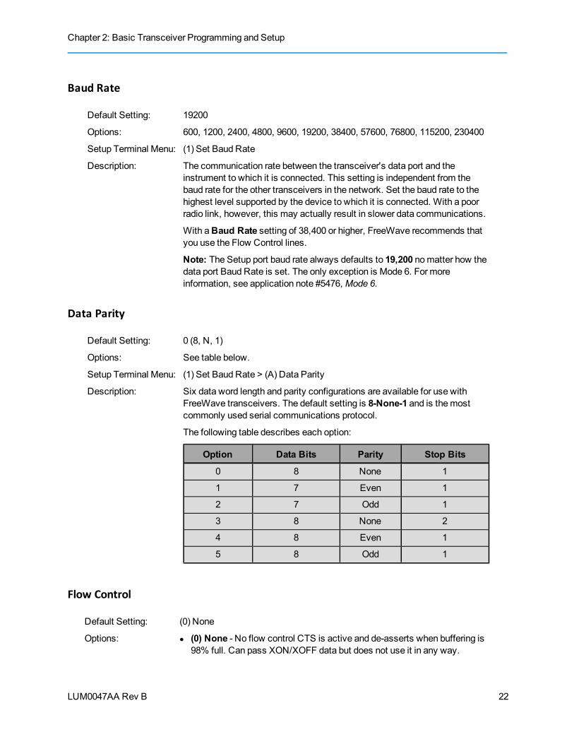
Data Parity
Default Setting: 0 (8, N, 1)
Options: See table below.
Setup Terminal Menu: (1) Set Baud Rate > (A) Data Parity
Description: Six data word length and parity configurations are available for use withFreeWave transceivers. The default setting is 8-None-1 and is themostcommonly used serial communications protocol.
The following table describes each option:
Option Data Bits Parity Stop Bits
0 8 None 1
1 7 Even 1
2 7 Odd 1
3 8 None 2
4 8 Even 1
5 8 Odd 1
Flow Control
Default Setting: (0) None
Options: l (0) None - No flow control CTS is active and de-asserts when buffering is98% full. Can pass XON/XOFF data but does not use it in any way.
22

FGR Wireless Data Transceivers
LUM0047AA Rev B
l (1) RTS - Uses standard RTS/CTS control lines.l (2) DTRl (3) DOT - Half Duplex
Setup Terminal Menu: (2) Set Baud Rate > (F) FlowControl
Description: Specifies the hardware flow control for the data port on the transceiver.FreeWave recommends using Flow Control if you are using a baud ratehigher than 19200.
Modbus RTU
Note:When using the transceiver inModbus RTU mode, theMaster Packet Repeatsetting in theMultiPoint Parameters tabmust match in every transceiver,regardless of whether the network is in Point-to-Point or MultiPoint mode. TheModbus RTU modemust be set to 1when transceivers are configured inRS485 or RS422mode.
Default Setting: 0 (Disabled)
Options: 0 to 9
Setup Terminal Menu: (1) Set Baud Rate > (B) Modbus RTU
Description: A setting other than 0 in this parameter causes the transceiver to wait for anamount of time “gathering” data before sending out the radio link.
l 0 (Disabled) - The transceiver sends data out through its radio link assoon as the data is received into the serial port. This is the defaultsetting.
l 1 - The transceiver waits for a number of slots equal to two times theMaster Packet Repeat setting before sending the received data out theradio link. For example, if theMaster Packet Repeat parameter is setto 3, the transceiver waits for 6 slots, gathering data up the whole time.At the end of the 6 slots, the transceiver sends all received data in one“burst.” This is the appropriate setting for most Modbus RTU devices.
l 2 or higher - The transceiver waits for a number of slots calculatedusing the following formula:
(Modbus RTU setting + Master Packet Repeat setting + 1) x 2
For example, in a transceiver where theModbus RTU setting is 2 andtheMaster Packet Repeat setting is 3, the transceiver waitsfor (2 + 3 + 1) x 2, or 12 slots.
Serial Interface
Default Setting: (0) RS232
Options: l (0) RS232 - Also used for TTL.l (1) RS422/Full Duplex RS485 -Modbus RTU modemust be enabled
and Turn Off Delay set to at least 4.
23

Chapter 2: Basic Transceiver Programming and Setup
LUM0047AA Rev B
l (2) Half Duplex RS485 -Modbus RTU modemust be enabled and TurnOff Delay set to at least 4.
l (3) DOT - DOT causes the CD line to indicate when data is transmittedon the serial port from the transceiver. When the transceiver is notsending data to the serial port, CD is de-asserted. When the transceiveris sending data to the serial port, CD is asserted. The CD line no longerhas any radio link state functionality. Turn Off Delayworks as describedin all radios. Turn On Delayworks as described on any Slave orSlave/Repeater - it has no functionality on theMaster.
If set to anything other than 0, theSetup Port parameter in the Baud Ratetabmust be set toDiagnostics Only.
Setup Terminal Menu: (1) Set Baud Rate > (C) RS232/485
Description: Use this option to set the protocol of the data port. This settingmust be 0 inTTL RF board products (FGR09Tx).
Setup Port
Important: Do not change this setting unless the correct programming cable isavailable for the new setting.
Default Setting: (3) Both
The factory setting is based on the transceiver type. A setting of 2 is usedwith Ethernet products andMirrored Bit products, a setting of 3 is usedotherwise.
Options: l (1) Main Only - Programming and reading a transceiver's setupinformation is done through the data port.
l (2) Diagnostics Only - Programming and reading a transceiver's setupinformation is done through the diagnostic port. If theSerial interface isset to anything other than RS232, then theSetup Portmust be set toDiagnostics Only.
l (3) Both - Programming and reading a transceiver's setup information isdone through either the data port or the diagnostic port .
Setup Terminal Menu: (1) Set Baud Rate > (D) Setup Port
Description: Determines which port on the transceiver, Main or Diagnostics, is used toaccess the parameter settings in Tool Suite or enter the Setupmainmenu inthe terminal interface.
Themain data port is the RS232 port. The diagnostics port is a 3-pinconnector on the rear panel of the OEM “Mini” series transceivers. Thediagnostic cable for this port (ASC0409DC) is available from FreeWave.TheOEMmodules use a 2-row, 2mm female connector. The diagnosticcable for this port (ASC2009DC) is available from FreeWave.
24
FGR Wireless Data Transceivers
LUM0047AA Rev B
Turn Off Delay
Default Setting: 0
Options: Any number between 0 and 9ms.
Setup Terminal Menu: (1) Edit Baud Rate > Turn Off Delay
Description: Specifies the time after the end of transmission of a character to the RS485bus that the transceiver stops driving the bus and releases the bus to otherdevices. The units are¼ of a character with a range of 0-9. An entry of 4means a delay equivalent to the duration of a full character. The default iszero delay.
For data rates of 1200 bits/S or slower, avoid setting the Turn Off Delayparameter higher than 4. At those rates the functionality of themicroprocessor changes so that a Turn Off Delay of 5 has the same effectas if set to 1, and a setting of 6 has the same effect as 2, and so on.
Note: Turn Off Delaymust be set to a value of at least 4 for RS422 andRS485 operation.
Turn On Delay
Default Setting: 0mS
Options: Any number between 1 and 9mS
Setup Terminal Menu: (1) Set Baud Rate > (E) Turn OnDelay
Description: Sets the delay between when the line drivers are turned on and when thedata leaves the data port.
Use Break to Access SetupNote: This setting is typically only used in OEM scenarios.
Default Setting: Disabled
Options: l (0) - Disabled - The break command is disabled in the radio.l (1) - Enabled - The Setupmenu is sent at 19200 bps.l (2) - Enabled - The Setupmenu is sent at the radio's current baud
rate. This setting is only available through the terminal interface
Setup Terminal Menu: (2) Set Baud Rate > (G) Use break to access setup
Description: Enables a break command to put the transceiver into Setupmode over thedata port. To send a break character the end devicemust hold the Tx dataline in the space voltage level for longer than 1 character time. If a characteris defined as having 1 start bit, 8 data bits, and 1 stop bit, the character timeis 10 bits, thus the Tx data linemust be held in the space voltage level for aperiod of time longer than 10 bits.
25
Chapter 2: Basic Transceiver Programming and Setup
LUM0047AA Rev B
Establishing Communication with Other Transceivers in the NetworkFor the transceivers in your network to communicate successfully, you need to tell the transceivers whatother devices are available for them to communicate with. Use one of the following options:
l Network ID - Used inMultiPoint Networks, theNetwork ID parameter is available in theMultiPoint Parameters tab. Each transceiver in a single network should be assigned the samenetwork ID. A Slave links with the first Master or Repeater that it hears that has amatchingNetwork ID.
Because theNetwork ID does not use serial numbers, MultiPoint Masters and Repeaters may bereplaced without reprogramming all of the Slaves in the network. TheNetwork ID function shouldbe used in conjunction with theSubnet ID feature (if necessary) to route data through thetransceiver network.
Without having the serial numbers in the Call Book, Slaves may establish communications withdifferent Masters that match the transceiver's golden settings described below, though not at thesame time. This is very useful in mobile MultiPoint applications.
For information about setting theNetwork ID parameter in aMultiPoint Network, see "Using theNetwork ID inMultiPoint Networks" on page 44.
l Call Book - The Call Book is required in Point-to-Point networks. The Call Book stores serialnumbers of transceivers in the network that are allowed to talk to a transceiver. Using the CallBook offers both security and flexibility in determining how FreeWave transceivers communicatewith each other.
Important:While the Call Book is an option in Point-to-MultiPoint networks,FreeWave strongly recommends using theNetwork ID feature in most applications. Ifa largeMultiPoint network is implemented using the Call Book and you want to add atransceiver to the network, or need to replace a transceiver, youmust physicallyreprogram each radio in the network and enter the new serial number in thetransceiver's Call Book. This can be a time consuming process and can cause a delayin getting your network back up and running.
For more information about defining the Call Book in a Point-to-Point network, see "Using the CallBook in Point-to-Point Networks" on page 62. For more information about defining the Call Book ina Point-to-MultiPoint network, see "Using the Call Book inMultiPoint Networks" on page 44.
"Golden Settings"A standard network requires that the following parameters are set the same on all transceivers in the network.FreeWave refers to these as the "golden" settings.
l Frequency Key
l Min Packet Size
l Max Packet Size
l Network ID
l RF Data Rate
26

FGR Wireless Data Transceivers
LUM0047AA Rev B
Transceivers that contain the same settings in all these parameters can communicate with each other. If youchoose to use the Call Book instead of theNetwork ID, or are running a Point-to-Point network, theappropriate serial numbers must be listed in the Call Book for each transceiver. If you are working with parallelRepeaters, the Frequency Key settingmay differ.
Setting RF Transmission CharacteristicsThe Transmission Characteristics parameters allow you tomodify settings that determine how data is sentbetween transceivers in your network. Many of these parameters must bemaintained throughout the networkfor proper functionality.
Important: The parameters in the Transmission Characteristics tab are only for theadvanced user who has a good understanding of the principles of RF transmission.
Several settings on a Slave or Repeater transceiver come from theMaster, and are therefore set only at theMaster. Settings that youmust set on eachSlave or Repeater include the following:
l Transmit Power
l Slave Security
l Retry TimeOut
l Hop Table Size
l Hop Table Version
l Hop Table Offset
You can leavemost parameters in the Transmission Characteristics tab set to their default settings whencompleting basic setup. However, youmust set the following parameters, and theymust be the same for alltransceivers in your network:
l Frequency Key
l Hop Table properties (Size, Version, andOffset)
l Max Packet Size
l Min Packet Size
l RF Data Rate
Set the following parameters in the Transmission Characteristics tab. These settings are available in the EditRadio Transmission Characteristics menu in the terminal interface, and apply to both Point-to-Point and Point-to-MultiPoint networks, unless indicated otherwise in their description.
Frequency Key (Golden Setting)Note: In MultiPoint networks, the Frequency Keymust be set identically in all
transceivers. Any transceiver with a Frequency Key different from theMasterwill not establish a link. In Point-to-Point networks theMaster’s settings takeprecedence over the Slave.
Default Setting: 5
Options: 0 to 9 and A to E
Note: Do not use Frequency Key E with the 915-928MHz, 916-920MHz,
27
Chapter 2: Basic Transceiver Programming and Setup
LUM0047AA Rev B
and 921-928MHz hop tables.
Setup Terminal Menu: (3) Edit Radio Transmission Characteristics > (0) FreqKey
Description: Fifteen choices are available for the Frequency Key setting, representing15 different pseudo-random hop patterns. Hopping patterns minimize theinterference with other FreeWave transceivers operating in the area.
For example, if 10 pairs of FreeWave transceivers are operating on differentnetworks in close proximity, setting a different Frequency Key valuereduces the chance that transceivers hop to the same frequency at thesame time. If two networks were to hop to the same frequency, the next hopwould be to a different frequency for both networks.
You can gain additional network separation by adjusting theMax PacketSize andMinimum Packet Size.
Use theHop Table Version, Hop Table Size, and Frequency Zone fieldsto definemore network differentiation by way of limiting the number andlocation of frequencies the transceivers may hop on in the 902-928MHzband.
Note: 900MHz transceivers do not use theHop Frequency Offset setting.
Frequency ZonesNote: In MultiPoint networks, this setting only needs to be set on theMaster. In a
Point-to-Point network, theMaster and the Slavemust havematchingFrequency Zone settings.
Default Setting: All zones selected
Options: See below.
Setup Terminal Menu: (3) Edit Radio Transmission Characteristics > (0) FreqKey > F >(3) Frequency Zone
Description: Divides the available band (902MHz to 928MHz) into smaller bands, in thiscase 16 smaller bands each consisting of 5, 7, and 8 frequency channelsdepending on the frequency zone. These 16 zones are stored in aWord,which is made up of 16 bits numbered 0 to 15. When displayed in LSB toMSB, these bits directly represent the zones that the transceiver operateson from lowest frequency to highest.
A value of 1 in the bit sequence instructs the transceiver to operate withinthe represented band. A value of 0 instructs the transceiver to bypass therepresented band. This feature should only be used with the standard hoptable.
Note: Youmust set theHop Table Version to 902-928 MHz when usingfrequency zones. If you select anotherHop Table Version, the limitationsof that selection would be applied to the hopping pattern as well. Forexample, if you select 916-920 as theHop Table Version, only themiddleof the band would be available in the pattern. Then, if frequency zones 5, 6,7, 8, and 9were set to 0, no allowable frequencies would be available for thetransceiver to use.
28

FGR Wireless Data Transceivers
LUM0047AA Rev B
Warning! FCC regulations require aminimum of 50 separate channels be used withina hop pattern. Use the table below to determine the number of frequency zonesrequired for legal communication.
EXAMPLE:1. Using zones 1-7 is equal to 49 channels; this is not legal according tothe FCC.
2. Using Zones 0-6 is equal to 50 channels; this is legal according to the FCC.
Binary Zone Number(LSB First) Beginning Freq. (MHz) Ending Freq. (MHz) Number Of Channels
1 902.2464 903.8592 8
2 904.0896 905.4720 7
3 905.7024 907.0848 7
4 907.3152 908.6976 7
5 908.9280 910.3104 7
6 910.5408 911.9232 7
7 912.1536 913.5360 7
8 913.7664 915.1488 7
9 915.3792 916.7616 7
10 916.9920 918.6048 8
11 918.8352 920.2176 7
12 920.4480 921.8304 7
13 922.0608 923.4432 7
14 923.6736 925.0560 7
15 925.2864 926.6688 7
16 926.8992 927.8208 5
To enable Frequency Zones in Tool Suite:
1. In the Tool Suite Configuration application, select the device to program and click the (3)Transmission Characteristics tab.
2. Click Frequency Zones in the Transmission Characteristics tab to display the frequency zonesavailable.
3. Select the check boxes next to the Frequency Zones to enable.
To enable Frequency Zones in the terminal interface:
1. From themain Setupmenu, select 3 Edit Radio Transmission Characteristics.
2. Select option 0 FreqKey.
29
Chapter 2: Basic Transceiver Programming and Setup
LUM0047AA Rev B
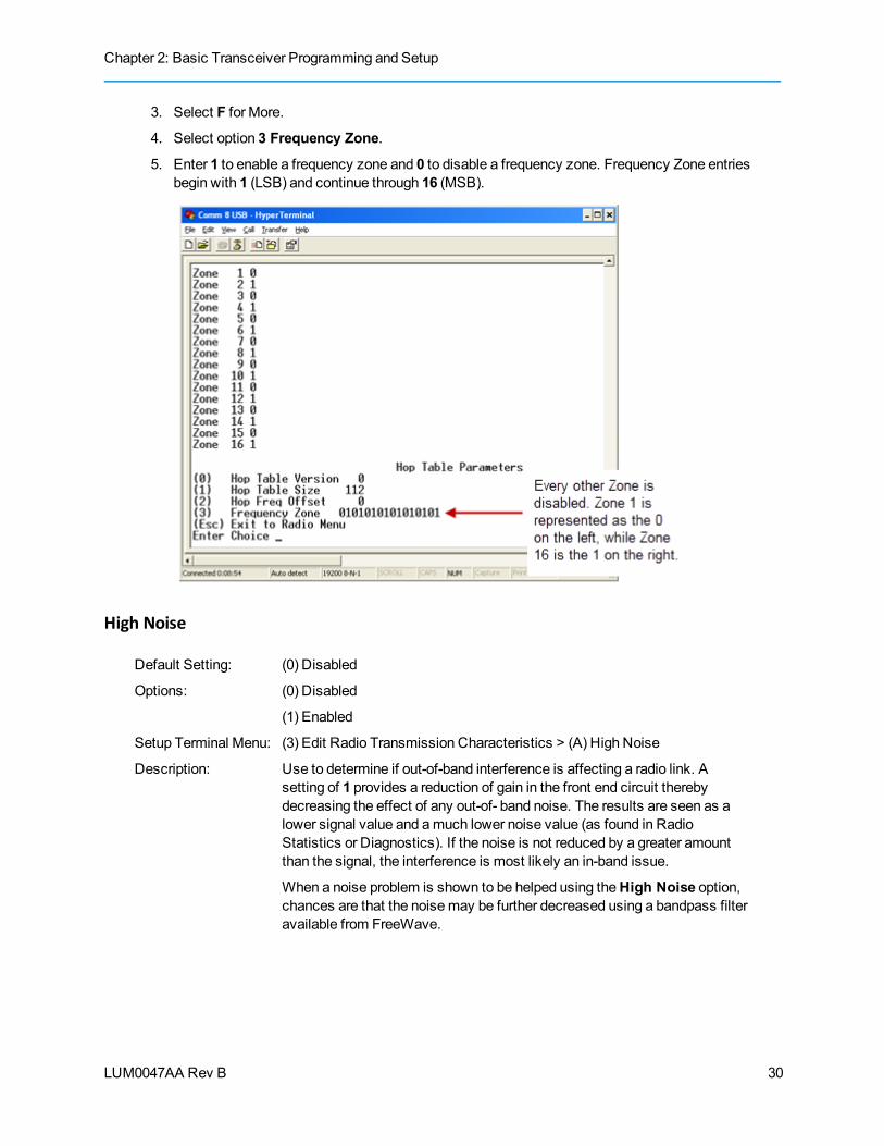
3. Select F for More.
4. Select option 3 Frequency Zone.
5. Enter 1 to enable a frequency zone and 0 to disable a frequency zone. Frequency Zone entriesbegin with 1 (LSB) and continue through 16 (MSB).
High Noise
Default Setting: (0) Disabled
Options: (0) Disabled
(1) Enabled
Setup Terminal Menu: (3) Edit Radio Transmission Characteristics > (A) High Noise
Description: Use to determine if out-of-band interference is affecting a radio link. Asetting of 1 provides a reduction of gain in the front end circuit therebydecreasing the effect of any out-of- band noise. The results are seen as alower signal value and amuch lower noise value (as found in RadioStatistics or Diagnostics). If the noise is not reduced by a greater amountthan the signal, the interference is most likely an in-band issue.
When a noise problem is shown to be helped using theHigh Noise option,chances are that the noisemay be further decreased using a bandpass filteravailable from FreeWave.
30

FGR Wireless Data Transceivers
LUM0047AA Rev B
Hop Table SizeNote: All transceivers in a network must have identical Hop Table settings to function
properly.
Default Setting: 112
Options: 50 to 112
Setup Terminal Menu: (3) Edit Radio Transmission Characteristics > (0) FreqKey > F >(1) Hop Table Size
Description: Defines how many separate channels a given network uses.
FreeWave recommends using Frequency Zones instead of theHop TableSize setting.
Warning! FCC regulations require aminimum of 50 separate frequency channels beused within a hop pattern. Using the Standard hop table, aminimum of 5 frequencyzones are required for legal communication.
Hop Table VersionNote: All transceivers in a network must have identical Hop Table settings to function
properly.
Default Setting: 902-928MHz
Options: l 902-928MHz, full band l 921-928MHz
l 915-928MHz l 902-911 - 919-928MHz, uses 902-928MHz with center frequencies of 911-919MHz notched out
l 903.744-926.3232MHz l 902-915MHz
l 916-920MHz
Do not use Frequency Key E (916-920MHz) with the 915-928MHz, 916-920MHz, and 921-928MHz hop tables.
Setup Terminal Menu: (3) Edit Radio Transmission Characteristics > (0) FreqKey > F >(0) Hop Table Version
Description: Determines the section of the 900MHz band the transceiver uses.
In the terminal interface, enter the number that corresponds to the frequencyband:
Number to Enter inTerminal Menu Frequency Band
0 902-928MHz, uses the full band
1 915-928MHz
2 903.744-926.3232MHz
31

Chapter 2: Basic Transceiver Programming and Setup
LUM0047AA Rev B
Number to Enter inTerminal Menu Frequency Band
3 916-920MHz
4 921-928MHz
5 902-911_919-928MHz, uses 902-928MHzwith center frequencies of 911-919MHznotched out
6 902-915MHz
Max Packet Size and Min Packet Size (Golden Setting)Note: In MultiPoint networks, theMax Packet Size andMin Packet Sizemust be set
identically in all transceivers. In Point-to-Point networks theMaster’s settingstake precedence over the Slave.
Default Setting: Max Packet Size = 8
Min Packet Size = 9
Options: Any number between 0 and 9.
Setup Terminal Menu: (3) Edit Transmission Characteristics > (1) Max Packet Size and (2) MinPacket Size
Description: TheMax andMin Packet Size settings and theRF Data Rate determinethe number of bytes in the packets. Throughput can be enhanced whenpacket sizes are optimized. In Point-to-Point mode, theMax andMinPacket Size settings do not havematerial impact on throughput unless115.2 KBaud is desired. However, this may have an impact on latency. Forexample, if small amounts of data are sent and large packet sizes areselected, a certain amount of time “wasted” between each packet would beseen.
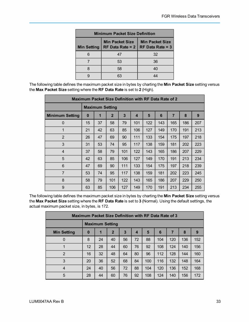
The following table defines theminimum packet size in bytes by charting theMin Packet Size setting versustheRF Data Rate setting. Using the default settings, the actual minimum packet size, in bytes,is 44.
Minimum Packet Size Definition
Min SettingMin Packet SizeRF Data Rate = 2
Min Packet SizeRF Data Rate = 3
0 15 8
1 21 12
2 26 16
3 31 20
4 37 24
5 42 28
32
FGR Wireless Data Transceivers
LUM0047AA Rev B
Minimum Packet Size Definition
Min SettingMin Packet SizeRF Data Rate = 2
Min Packet SizeRF Data Rate = 3
6 47 32
7 53 36
8 58 40
9 63 44
The following table defines themaximum packet size in bytes by charting theMin Packet Size setting versustheMax Packet Size setting where theRF Data Rate is set to 2 (High).
Maximum Packet Size Definition with RF Data Rate of 2
Maximum Setting
Minimum Setting 0 1 2 3 4 5 6 7 8 9
0 15 37 58 79 101 122 143 165 186 207
1 21 42 63 85 106 127 149 170 191 213
2 26 47 69 90 111 133 154 175 197 218
3 31 53 74 95 117 138 159 181 202 223
4 37 58 79 101 122 143 165 186 207 229
5 42 63 85 106 127 149 170 191 213 234
6 47 69 90 111 133 154 175 197 218 239
7 53 74 95 117 138 159 181 202 223 245
8 58 79 101 122 143 165 186 207 229 250
9 63 85 106 127 149 170 191 213 234 255
The following table defines themaximum packet size in bytes by charting theMin Packet Size setting versustheMax Packet Size setting where theRF Data Rate is set to 3 (Normal). Using the default settings, theactual maximum packet size, in bytes, is 172.
Maximum Packet Size Definition with RF Data Rate of 3
Maximum Setting
Min Setting 0 1 2 3 4 5 6 7 8 9
0 8 24 40 56 72 88 104 120 136 152
1 12 28 44 60 76 92 108 124 140 156
2 16 32 48 64 80 96 112 128 144 160
3 20 36 52 68 84 100 116 132 148 164
4 24 40 56 72 88 104 120 136 152 168
5 28 44 60 76 92 108 124 140 156 172
33

Chapter 2: Basic Transceiver Programming and Setup
LUM0047AA Rev B
Maximum Packet Size Definition with RF Data Rate of 3
Maximum Setting
Min Setting 0 1 2 3 4 5 6 7 8 9
6 32 48 64 80 96 112 128 144 160 176
7 36 52 68 84 100 116 132 148 164 180
8 40 56 72 88 104 120 136 152 168 184
9 44 60 76 92 108 124 140 156 172 188
Referencing the default settings, theMaster transmits up to 172 bytes on every hop. If fewer than 172 bytesare transmitted, the balance is allocated to the Slave's transmission, plus the quantity in theMin Packet Sizesetting.
For example, if a Master transmits 100 bytes, the Slave then has a total of 116 bytes available:
(72 (“leftover bytes”) + 44 (Min packet size) )
MCU Speed
Default Setting: (0) Normal
Options: l (0) Normal (low speed) - Reduces current consumption.l (1) Fast (high speed) - Required for 230 KBaud and greater data port
rate.
Setup Terminal Menu: (3) Edit Radio Transmission Characteristics > (B) MCU Speed
Description: Controls the speed of theMicro Controller Unit (MCU) in the transceiver.
Remote LEDNote: This feature is available in firmware versions 2.64 and higher.
Default Setting: (0) Local Only
Options: l (0) Local Only - Only the LEDs on the radio board are enabled.l (1) Remote and Local - LEDs on the radio board and remote LEDs
through the diagnostic port are enabled.l (2) Remote Only - LEDs on the radio board are disabled. Remote LEDs
through the diagnostic port are enabled.
Setup Terminal Menu: (3) Edit Radio Transmission Characteristics > (C) Remote LED
Description: If you are using a transceiver with the optional 20-pin connector, you canuse this option to connect remote LEDs through the diagnostics port.
This featuremay be used to save power in MultiPoint Repeaters. By turningoff the on-board LEDs (setting = 2) the current consumption is reduced. Toreduce current consumption in Slaves, use Low Power (setting = 1). LowPower does not work with MultiPoint Repeaters because Repeaters areconstantly transmitting. Remote LED drives the Diagnostic port, which has
34
FGR Wireless Data Transceivers
LUM0047AA Rev B
a small amount of current draw.
When using remote LEDs, the center (TX) LED does not output a signal fora green LED when in Setupmode. TheGreen TX LED has no remote pinout.
Retry Time Out
Default Setting: 255
Options: Any number between 0 and 255 inMultiPoint networks.
Any number between 151 and 255 in Point-to-Point networks.
Setup Terminal Menu: (3) Edit Transmission Characteristics > (8) Retry TimeOut
Description: TheRetry Time Out parameter in a Slave or Repeater sets the delay theunit waits before dropping the connection to aMaster or Repeater. Thefactory default is set at themaximum of 255. Themaximum settingmeansthat if 1 packet in 255 is sent successfully from theMaster to the Slave orRepeater, the link is maintained. Theminimum setting is 8. This allows aSlave or Repeater to drop a connection if less than 1 in 8 consecutivepackets is successfully received from theMaster. The function in theMaster is effectively the same. With a setting of 255, theMaster allows aSlave or Repeater to stay connected as long as 1 packet in 255 issuccessfully received at theMaster.
TheRetry Time Out parameter is useful when aMultiPoint network has arovingMaster or Slave(s). As the link gets weaker, a lower setting allows apoor link to break in search of a stronger one.
Note: SettingRetry Time Out to 20 in theMultiPoint Master isrecommended in areas where several FreeWave networks exist. Thisrecommended setting allows Slaves and Repeaters to drop the connectionif the link becomes too weak, while at the same time prevent errantdisconnects due to interference from neighboring networks.
While intended primarily for MultiPoint networks, theRetry Time Outparameter may also bemodified in Point-to-Point networks. However, thevalue in Point-to-Point mode should not be set to less than 151.
RF Data Rate (Golden Setting)Note: In MultiPoint networks, theRF Data Ratemust be set identically in all
transceivers. Any transceiver with anRF Data Rate different from theMasterwill not establish a link. In Point-to-Point networks theMaster’s settings takeprecedence over the Slave.
Default Setting: (3) Normal
Options: l (2) High - 154 kbpsl (3) Normal - 115.2 kbps
Setup Terminal Menu: (3) Edit Transmission Characteristics > (4) RF Data Rate
35
Chapter 2: Basic Transceiver Programming and Setup
LUM0047AA Rev B
Description: FreeWave transceivers have twoRF Data Rate settings; 2 (High) and 3(Normal). RF Data Rate should not be confused with the serial port BaudRate. Use setting 2 (RF Speed of 153.6 kbps) when the transceivers areclose together and you need to optimize data throughput. Use setting 3 (RFSpeed of 115.2 kbps) when the transceivers are farther away and a soliddata link is preferred over data throughput.
RTS to CTS
Note: TheRTS to CTS option is only available in RS232mode. It is notrecommended to enable this feature when operating at baud rates above38.4 kB.
Default Setting: (0) Disabled
Options: l (0) Disabledl (1) Enabledl (2) Line AlarmSetting 2 is described in detail in the application note #5437, DTR to CTSLine Alarm Feature.
Setup Terminal Menu: (3) Edit Transmission Characteristics > (7) RTS to CTS
Description: Use this option to set the RTS line on theMaster transceiver to control theCTS line of the Slave. In MultiPoint networks, theMaster RTS line controlsall Slaves’ CTS lines. When enabled, the CTS line ceases to function asflow control.
WithRTS to CTS enabled, theMaster senses the RTS line prior to allscheduled packet transmissions. If the state has changed, theMaster thentransmits amessage to the Slave with the new status. This transmissionoccurs regardless of data being sent. If data is ready to be sent, the RTSstatus message is sent in addition to the data. In Point-to-Point mode, theMaster continues sending the new status message until it receives anacknowledgment from the Slave. In MultiPoint mode, theMaster repeatsthemessage the number of times equal to theMaster Packet Repeat valuein theMultiPoint Parameters tab.
Master transmit times are completely asynchronous to the occurrence ofany change of the RTS line; the latency time from RTS to CTS is variable.TheMax andMin Packet Size parameters determine this duration. Settingboth parameters to their maximum value of 9 produces amaximum latencytime of approximately 21ms, given no Repeaters in the network. At theminimum settings forMax andMin Packet Size (0), the time isapproximately 5.9ms. This latency can increase significantly if packets arelost between theMaster and Slave. In Point-to-MultiPoint mode, noabsolute guarantee is made that the state change is communicated to allSlaves. In MultiPoint networks with Repeaters present, the latency iscumulative for each serial Repeater.
36
FGR Wireless Data Transceivers
LUM0047AA Rev B
For example, if the latency between theMaster and the first Repeater is 15ms, and two serial Repeaters are present, the total latency is 45ms. (M—R1 (15ms) + R1—R2 (15ms) + R2—S (15ms) = 45ms)
Note: TheRTS to CTS feature does not function in Point-to-Point networksthat contain a Repeater. If this feature is needed in such network, themodeshould be changed to Point-to-MultiPoint.
If DTR Connect in theMultiPoint Parameters tab is enabled and set to 2,the RTS to CTS feature does not work. If DTR Connect is enabled and setto 1, RTS to CTS mode takes precedence over the functionality of the CTSline on the Slave relating to theDTR Connect feature.
Slave SecurityNote: Slave Security has no effect in Point-to-MultiPoint networks where the
Network ID is used.
Default Setting: (0) On
Options: (0) On
(1) Off
Setup Terminal Menu: (3) Edit Transmission Characteristics > (6) Slave Security
Description: Slave Security allows Slave transceivers to accept transmissions from aMaster not included in the Call Book. The default setting of 0 (On) meansonly Masters in the Slaves’ Call Book may link to that Slave.
Slave Securitymay be disabled (setting of 1) allowing any Master to callthe Slave.
Slave Securitymust be set to 1when the unit is operating in Mode 6,Slave/Master Switchable or a Point-to-Point network where the Slavemayneed to accept calls frommore than 10 different Masters. WhenSlaveSecurity is set to 1, the transceiver accepts calls from any other FreeWavetransceiver. Additional network security measures may be taken to preventunauthorized access, such as changing default settings for FrequencyKey, Hop Table, or Frequency Zones.
Transmit Power
Default Setting: 10
Options: Any number between 0 and 10
Setup Terminal Menu: (3) Edit Transmission Characteristics > (5) RF Xmit Power
Description: Sets the output power of the transceiver.
Note:When testing transceivers at your facility and they are in closeproximity to one another, set the Transmit Power to a low number. Whenyou deploy transceivers to the field, raise the Transmit Power numberaccordingly.
37

Chapter 2: Basic Transceiver Programming and Setup
LUM0047AA Rev B
Transmit Rate
Default Setting: (1) Normal
Options: (0) Diagnostics
(1) Normal
Setup Terminal Menu: (3) Edit Transmission Characteristics > (3) Xmit Rate
Description: FreeWave transceivers have two available Transmit Rate settings. Thesetting for normal operation of the transceiver is 1. When set to 0, thetransceivers transmit back and forth continuously regardless if they haveany actual data. 0 should be used only as a diagnostic tool and not fornormal operation. The strength of the signal may be gauged by the Clear toSend (CTS) LED. A solid red CTS LED indicates a strong signal; a blinkingCTS LED indicates a weaker signal.
0 is useful to qualitatively gauge signal strength in Point-to-Point mode.
38
LUM0047AA Rev B
Chapter 3: ConfiguringPoint-to-MultiPoint Networks
When installingMultiPoint networks it is important to do some up front planning around the devices you aregoing to implement and the route your data is going to take back to theMaster. A MultiPoint network cancontain the following devices:
l Only oneMaster. All communications are from and to theMaster.
l An unlimited number of Slaves (remote sites).
l An unlimited number of Repeaters between any Slave and theMaster.
l Serial Repeaters can be Slaves and Repeaters at the same time.
This chapter builds on the settings described in the previous chapters and provides details about the followingsetup that applies specifically to aMultiPoint network:
l Point-to-MultiPoint network characteristics.
l Using the Network ID or the Call Book to establish which transceivers in the network cancommunicate with each other.
l Using subnet IDs to route communication through the network, back to theMaster.
l Settings and recommendations for additional parameters that apply to aMultiPoint network.
l Conserving power in devices within the network.
l Running network diagnostics.
39
Chapter 3: Configuring Point-to-MultiPoint Networks
LUM0047AA Rev B
Point-to-MultiPoint Network CharacteristicsA Point-to-MultiPoint network has the following unique characteristics.
Golden SettingsA Point-to-MultiPoint network requires that the golden settings, as described on page 26, are set the same onall transceivers in the network.
If several independent MultiPoint networks are to be located in close proximity the planning becomes morecritical. In such cases, it becomes very important to include as much frequency and time diversity as possiblethrough use of differentMin and Max Packet Size. In some instances the use of theMultiMaster Syncoptionmay be required. For more information, about theMultiMaster Sync setting, see application note#5412, Synchronizing CollocatedMasters, or contact FreeWave Technical Support.
In almost all MultiPoint networks, the Frequency Key is the same for all transceivers. In other networks,where parallel Repeaters are introduced, the Frequency Key value needs to change.
Master-to-Slave CommunicationMaster-to-Slave communication within aMultiPoint network has the following characteristics:
l Data packets sent from theMaster include a 32-bit CRC.
l TheMaster repeats its data broadcast between 0 to 9 times, depending on the setting in theMaster Packet Repeat setting. For more information, see "Master Packet Repeat" on page 50.
l Slaves and Repeaters do not send acknowledgements to theMaster when they receive data.When any Slave in the network receives the data packet from theMaster with the 32-bit CRC, thatSlave ignores any additional repeats of the data, and passes the data to its RS232 port.
l Repeaters in the network send data to Slaves and other Repeaters.
Slave-to-Master CommunicationSlave-to-Master communication within aMultiPoint network has the following characteristics:
l Data packets sent from the Slave to theMaster include a 32-bit CRC.
l When theMaster successfully receives data, it sends an acknowledgement to the Slave andpasses the data to its RS232 port.
Point-to-MultiPoint Network Quick StartThe following is a quick start guide for setting up two transceivers in Point-to-MultiPoint mode. This modeallows for aMaster to communicate with several Repeaters and Slaves simultaneously.
Point-to-MultiPoint Network Quick Start (Tool Suite):
1. Connect the transceiver to the serial port of a computer either through a serial cable or via thediagnostics cable. Make sure to connect the radio to a power source.
Power supply ranges and recommendations vary depending onmodel. Verify the specifications forthemodel you are using prior to connecting power.
40
FGR Wireless Data Transceivers
LUM0047AA Rev B
2. Open a Tool Suite session, select theConfiguration application, and ensure the correct port isselected in the Com Port field in the upper left of the Configuration ribbon.
3. From the Networks section of the Configuration ribbon, select the network in which the radioresides or click Add Network to create a new network in Tool Suite.
4. Click Read Radio in the Configuration ribbon to read the radio's current settings.
l If you are using a diagnostics cable to connect to the radio, the radio automatically goes intoSetupmode.
l If you are using a data cable to connect to the radio, you are prompted to press the radio'sSetup button to put the radio in Setupmode.
l When in Setupmode, all three LEDs on the radio display solid green.
5. Select the OperationMode tab.
In theModem Mode field, select 2 to set the radio as a Point-to-MultiPoint Master or select 3 toset the radio as a Point-to-MultiPoint Slave.
Note: A network can have only oneMaster.
6. Select the Baud Rate tab.
Change the Baud Rate, Data Parity, andModbus RTU to match the device that the radio is to beattached to.
7. Select the Transmission Characteristics tab.
Set the following parameters so they are identical on all radios in the network:
l Frequency Key
l Max Packet Size
l Min Packet Size
l RF Data Rate
If several independent MultiPoint networks are located in close proximity, it becomes veryimportant to include as much frequency and time diversity as possible through use of differentFrequency Key, Min and Max Packet Size, andHop Table settings.
Changing these settings from the factory defaults may help to eliminate interference from otherFreeWave networks.
8. Select theMultiPoint Parameters tab.
In theNetwork ID field, set the value to any value between 1 and 4095, except 255. FreeWaverecommends setting theNetwork ID to the last three or four digits of theMaster radio's serialnumber, as this is a number you can look up if necessary. This valuemust be the same in allradios in the network.
Point-to-MultiPoint Network Quick Start (Terminal Interface):
1. Connect the transceiver to the serial port of a computer either through a serial cable or via thediagnostics cable. Make sure to connect the radio to a power source.
Power supply ranges and recommendations vary depending onmodel. Verify the specifications forthemodel you are using prior to connecting power.
41
Chapter 3: Configuring Point-to-MultiPoint Networks
LUM0047AA Rev B
2. Open a terminal emulator session and use the following settings when connecting the radio. Youcan also use Setup Terminal within Tool Suite if a terminal emulator is unavailable:
l Connect to COMx (where 'x' is the number of the Com port being connected).
l Set the following:
l Data Rate - 19,200
l Data Bits - 8
l Parity - none
l Stop bits – 1
l Flow control – none
3. Press theSetup button on the radio. If using the diagnostics cable, press Shift-U (capital U).
l The three LEDs on the radio should all turn green, indicating Setupmode.
l TheMainmenu displays on the screen.
4. Press 0 to access the OperationModemenu.
l Press 2 to set the radio as a Point-to-MultiPoint Master or press 3 to set the radio as a Point-to-MultiPoint Slave.
l Press Esc to return to theMainmenu.
Note: A network can have only oneMaster.
5. Press 1 in theMainmenu.
l Change theBaud Rate, Data Parity, andModbus RTU to match the device that the radio isto be attached to.
l Press Esc to return to theMainmenu.
6. Press 3 in theMainmenu.
l Set the following parameters so they are the same on all radios in the network:
l FreqKey
l Max Packet Size
l Min Packet Size
l RF Data Rate
The Frequency Key options is located in the F submenu after you press 0 to access the FrequencyKey menu inMainmenu 3.
Changing these values may help to eliminate interference from other FreeWave networks.
l Press Esc to return to theMainmenu.
7. Press 5 in theMainmenu.
l Set theNetwork ID value to any value between 1 and 4095, except 255. FreeWaverecommends setting theNetwork ID to the last three or 4 digits of the radio's serial number.
l Ensure this value is the same on every radio in the network.
8. Press Esc to exit the Setupmenu and resume normal radio operation.
42

FGR Wireless Data Transceivers
LUM0047AA Rev B
Point-to-MultiPoint Operation LEDsMaster Slave Repeater
Condition
CarrierDetect(CD)
Transmit(Tx)
Clear toSend(CTS)
CarrierDetect(CD)
Transmit(Tx)
Clear toSend(CTS)
CarrierDetect(CD)
Transmit(Tx)
Clear toSend(CTS)
Powered, not linked Solid redbright
Solid reddim
Off Solid redbright
Off Blinkingred
Solid redbright
Off Blinkingred
Repeater and Slavelinked toMaster, no data
Solid redbright
Solid reddim
Off Solidgreen
Off Solid redbright
Solidgreen
Solid reddim
Solid redbright
Repeater and Slavelinked toMaster, Mastersending data to Slave
Solid redbright
Solid reddim
Off Solidgreen
Off Solid redbright
Solidgreen
Solid reddim
Solid redbright
Repeater and Slavelinked toMaster, Slavesending data toMaster
Solid greenRCV data
or Solid redbright
Solid reddim
Intermittentflash red
Solidgreen
Intermittentflash red
Solid redbright
Solidgreen
Solid redbright
Solid redbright
Master with diagnosticsprogram running
Solid redbright
Solid reddim
Intermittentflash red
Solidgreen
Intermittentflash red
Solid redbright
Solidgreen
Solid redbright
Solid redbright
* in an idle condition, the CTS LED is solid red with a solid link, as the link weakens the CTSLED on the Repeater and Slave begins to blink
Overlapping MultiPoint NetworksOverlappingMultiPoint networks may be set up effectively with FreeWave transceivers when several keyparameters are set correctly. OverlappingMultiPoint networks are defined as networks using differentMasters, which share or overlap in a specific geographic area. It may also include co-located transceiversconfigured into different networks. For more information, see application note #5412, SynchronizingCollocatedMasters (Multi-Master Sync Mode).
Co-locatedMultiPoint networks require the following parameters be unique for each network:
l Network ID, unless using the Call Book
l Frequency Key (in conjunction with Repeater Frequency)
l Max Packet Size
l Min Packet Size
Formore information about the installation of Point-to-MultiPoint networks, contact FreeWave TechnicalSupport.
Establishing Communication with Other Transceivers in a MultiPointNetworkFor the transceivers in your network to communicate successfully, you need to tell the transceiver what otherdevices are available for them to communicate with. You can use theNetwork ID or the Call Book. FreeWave
43

Chapter 3: Configuring Point-to-MultiPoint Networks
LUM0047AA Rev B
recommends using theNetwork ID option instead of the Call Book inMultiPoint networks. Because theNetwork ID does not use serial numbers, MultiPoint Masters and Repeaters may be added or replacedwithout reprogramming all of the Slaves in the network.
Using the Network ID in MultiPoint NetworksTheNetwork ID parameter is located in theMultiPoint Parameters tab. A transceiver from the factory has aNetwork ID setting of 255, which enables the Call Book. Assign each transceiver in a single network thesameNetwork ID. A Slave links with the first Master or Repeater it hears that has amatchingNetwork ID.
Keep the following inmind when setting theNetwork ID:
l The value can be any value between 0 and 4095, except 255.
l To help ensure your ID is unique to your network, avoid using numbers that coincide with nearbylandmarks or highways.
l FreeWave recommends aNetwork ID of four characters. For example, the last four digits of theMaster's serial number, which is ensured to be unique and does not overlap with other nearbyFreeWave networks.
l Use theNetwork ID function in conjunction with theSubnet ID feature (if necessary) to route datathrough the transceiver network.
Using the Call Book in MultiPoint NetworksAlthough not recommended, the Call Book is an option in MultiPoint networks. If theNetwork ID feature isused in aMultiPoint network, no entries are needed in the Call Book of any of the transceivers.
Important: FreeWave recommends using theNetwork ID feature in aMultiPointnetwork. Using the Call Book in aMultiPoint network can cause delay in resumingcommunication if a Master is damaged.
For information about setting the Call Book, see "Using the Call Book in Point-to-Point Networks" on page 62.
In aMultiPoint network, the Slaves and Repeaters are not listed in theMaster's Call Book. A Slavemust havetheMaster and any Repeater it is going to use in its Call Book.
The following examples show the Call Books of aMultiPoint network comprised of aMaster, Repeater, andSlave in which the Slave can communicate either through the Repeater or directly to theMaster:
MultiPoint Master Call Book (Unit Serial Number 900-0001)
Entry Number Repeater 1 Repeater 2(0) 000-0000(1) 000-0000
No serial number entries are necessary in theMaster’s Call Book.
MultiPoint Repeater Call Book (Unit Serial Number 900-0002)
Entry Number Repeater 1 Repeater 2(0) 900-0001(1) 000-0000
MultiPoint Slave Call Book (Unit Serial Number 900-0003)
44
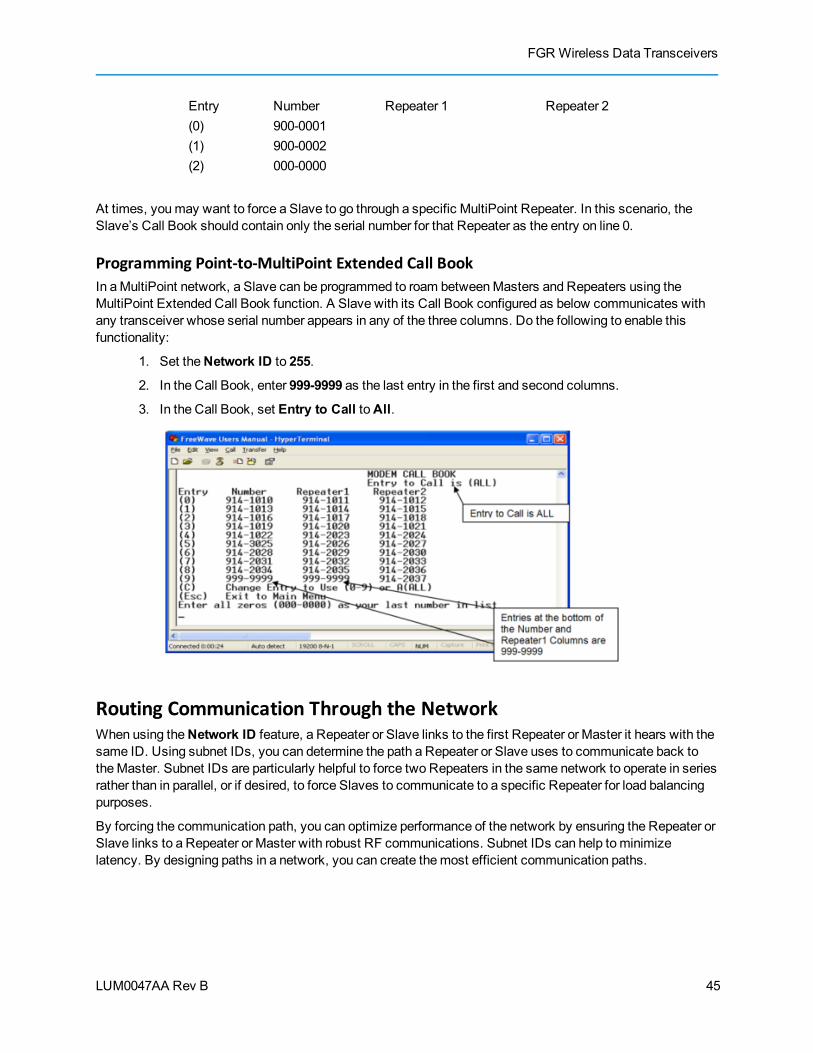
FGR Wireless Data Transceivers
LUM0047AA Rev B
Entry Number Repeater 1 Repeater 2(0) 900-0001(1) 900-0002(2) 000-0000
At times, youmay want to force a Slave to go through a specific MultiPoint Repeater. In this scenario, theSlave’s Call Book should contain only the serial number for that Repeater as the entry on line 0.
Programming Point-to-MultiPoint Extended Call BookIn aMultiPoint network, a Slave can be programmed to roam betweenMasters and Repeaters using theMultiPoint Extended Call Book function. A Slave with its Call Book configured as below communicates withany transceiver whose serial number appears in any of the three columns. Do the following to enable thisfunctionality:
1. Set theNetwork ID to 255.
2. In the Call Book, enter 999-9999 as the last entry in the first and second columns.
3. In the Call Book, set Entry to Call toAll.
Routing Communication Through the NetworkWhen using theNetwork ID feature, a Repeater or Slave links to the first Repeater or Master it hears with thesame ID. Using subnet IDs, you can determine the path a Repeater or Slave uses to communicate back totheMaster. Subnet IDs are particularly helpful to force two Repeaters in the same network to operate in seriesrather than in parallel, or if desired, to force Slaves to communicate to a specific Repeater for load balancingpurposes.
By forcing the communication path, you can optimize performance of the network by ensuring the Repeater orSlave links to a Repeater or Master with robust RF communications. Subnet IDs can help tominimizelatency. By designing paths in a network, you can create themost efficient communication paths.
45

Chapter 3: Configuring Point-to-MultiPoint Networks
LUM0047AA Rev B
Assigning Subnet ID ValuesSubnet IDs consist of two parts, both available in theMultiPoint Parameters tab:
l Rx - This setting identifies which transceiver a Repeater or Slave listens to. In the terminalinterface, this is theRcv Subnet ID.
l Tx - This setting identifies the ID on which this device transmits, and in turn which devices listen toit. The Tx Subnet ID parameter is relevant for MultiPoint Masters and Repeaters only. In theterminal interface, this is theXmt Subnet ID.
The default (disable) setting for bothRx and Tx is F, which is a visual way to indicate that the device is thefinal in the line of communication and does not use a subnet ID. A MultiPoint Slave with aSubnet ID of F,Fdoes not roam from one Repeater or network to the next, it only links to aMaster or Repeater that has either aTx setting of 0 or an F,F Subnet ID.
Setting bothRx and Tx Subnet ID to 0 allows amobile Slave to roam from subnet to subnet, and possiblyfrom network to network, provided theNetwork ID,Max and Min Packet Size, andRF Data Rates are thesame between networks.
Note: A Master with firmware before 2.40 always transmits and receives on 0. Withfirmware 2.40 and greater theMaster may be set to use alternateSubnet IDvalues. Changing these settings on theMaster is not recommended undernormal circumstances.
With firmware 2.40 and above, theSubnet ID default is F,F. A MultiPointMaster with an F,F Subnet ID behaves the same as if theSubnet ID was setto 0,0. A MultiPoint Slave with aSubnet ID of F,F does not roam from oneRepeater or network to the next, it only links to aMaster or Repeater that haseither a Transmit Subnet of 0 or an F,F Subnet ID.
The following illustration depicts a network in which subnet IDs are used to force communication. The subnetsettings follow.
Subnet ID Settings for This Example
Transceiver Rx Tx Additional Information
Master 0 0 The default settings (F, F) actually use 0, 0. TheRx Subnet on theMaster has no effect on the network.
Repeater1 0 1 A 0 forces the transceiver to link only to theMaster.
Repeater2 1 2 Rx Subnet = 1 forces communication through Repeater 1. Repeater1 transmits on subnet 2.
46
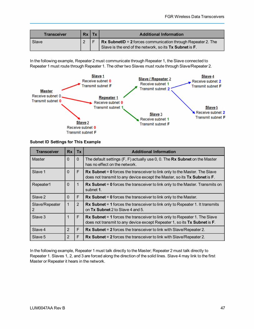
FGR Wireless Data Transceivers
LUM0047AA Rev B
Transceiver Rx Tx Additional Information
Slave 2 F Rx SubnetID = 2 forces communication through Repeater 2. TheSlave is the end of the network, so its Tx Subnet is F.
In the following example, Repeater 2must communicate through Repeater 1, the Slave connected toRepeater 1must route through Repeater 1. The other two Slaves must route through Slave/Repeater 2.
Subnet ID Settings for This Example
Transceiver Rx Tx Additional Information
Master 0 0 The default settings (F, F) actually use 0, 0. TheRx Subnet on theMasterhas no effect on the network.
Slave 1 0 F Rx Subnet = 0 forces the transceiver to link only to theMaster. The Slavedoes not transmit to any device except theMaster, so its Tx Subnet is F.
Repeater1 0 1 Rx Subnet = 0 forces the transceiver to link only to theMaster. Transmits onsubnet 1.
Slave 2 0 F Rx Subnet = 0 forces the transceiver to link only to theMaster.
Slave/Repeater2
1 2 Rx Subnet = 1 forces the transceiver to link only to Repeater 1. It transmitson Tx Subnet 2 to Slave 4 and 5.
Slave 3 1 F Rx Subnet = 1 forces the transceiver to link only to Repeater 1. The Slavedoes not transmit to any device except Repeater 1, so its Tx Subnet is F.
Slave 4 2 F Rx Subnet = 2 forces the transceiver to link with Slave/Repeater 2.
Slave 5 2 F Rx Subnet = 2 forces the transceiver to link with Slave/Repeater 2.
In the following example, Repeater 1must talk directly to theMaster; Repeater 2must talk directly toRepeater 1. Slaves 1, 2, and 3 are forced along the direction of the solid lines. Slave 4may link to the firstMaster or Repeater it hears in the network.
47

Chapter 3: Configuring Point-to-MultiPoint Networks
LUM0047AA Rev B
Subnet ID Settings for this Example
Transceiver Rx Tx Other Information
Master 0-F 0-F The default settings (F, F) actually use 0, 0. TheRx Subnet on theMaster has no effect on the network.
Repeater1 0 1 A 0 forces the transceiver to link only to theMaster.
Repeater2 1 2 Rx Subnet = 1 forces communication through Repeater1.Repeater1 transmits on SubnetID 1.
Slave 1 0 0 or F Rx Subnet = 0 forces communication throughMaster.
Slave 2 1 0 or F Rx Subnet = 1 forces communication through Repeater1.
Slave 3 2 0 or F Rx SubnetID = 2 forces communication through Repeater2.
Slave 4 0 0 The 0,0 setting allows the Slave to link with the first Master orRepeater it hears with the sameNetwork ID.
Setting Other MultiPoint ParametersThe other MultiPoint Parameters options allow you tomodify several different parameters in the transceiverthat determine the characteristics of aMultiPoint network.
Set the following parameters in theMultiPoint Parameters tab. These settings are available in theMultiPointParameters menu in the terminal interface.
1 PPS Enable Delay
Default Setting: 255
Options: 255 to disable 1 PPS
0 to 254 to enter the delay
Setup Terminal Menu: (5) Edit MultiPoint Parameters > (9) 1 PPS Enable/Delay
48

FGR Wireless Data Transceivers
LUM0047AA Rev B
Description: The 1 PPS Enable/Delay setting allows the a 1PPS signal to propagatefrom theMaster to all Slaves in aMultiPoint network. When this parameteris enabled a properly generated pulse applied on the DTR line of theMasterprovides a 1 PPS pulse on the CD line of any Slave in the network.
Follow the steps below to use the 1 PPS Enable/Delay feature.
To setup 1PPS Enable/Delay:
1. Set the 1 PPS Enable/Delay parameter to 0 in theMaster.
TheMaster must have a 1 PPS pulse on the DTR pin.
2. Enable the 1 PPS Enable/Delay parameter on the Slaves. Slaves are calibrated at the factory.
To calibrate a Slave in 1PPS Enable/Delay mode:
1. Trigger an oscilloscope on the 1 PPS pulse on the DTR line of theMaster.
2. Monitor the CD line of the Slave.
3. If the timing on the Slave differs from theMaster it may be adjusted via the value in the Slave's 1PPS Enable/Delay parameter. The difference in time between each incremental integer value is542.534 nS. Changing the parameter to higher values decreases the Slave time delay andchanging the parameter to lower values increases the time delay.
When properly calibrated, the CD line Slave transceiver outputs a pulse that goes high for about 2ms in synchwith the 1 PPS pulse on theMaster. The output on the Slave occurs within 20microseconds of the input to theMaster.
Important:When 1 PPS is enabled, theMaster must have a 1 PPS pulse on its DTRpin, otherwise the RF network does not function.
Diagnostics
Default Setting: 0 (Disabled)
Options: Any number between 0 and 128
Setup Terminal Menu: (5) Edit MultiPoint Parameters > (B) Diagnostics
Description: Allows diagnostics data in the Network Diagnostics application withinTool Suite to be viewed at theMaster in parallel with application data. Thesetting in this parameter determines how many slots out of 128 arededicated to diagnostics. For example, if set to 10, 1 out of every 10 dataslots is for diagnostics data; if set to 100, 1 out of every 100 data slots is fordiagnostics data.
Diagnostics is always secondary to actual transmitted data.
For more information, see "Reading Diagnostics in Tool Suite" on page 56.
49
Chapter 3: Configuring Point-to-MultiPoint Networks
LUM0047AA Rev B
DTR Connect
Default Setting: (0) Off
Options: l (0) Off - When set to off in the Slave, the transceiver transmits when thedata is received.
l (1) DTR Sensing - Forms a Point-to-Point link with theMaster when theDTR line is high to send data.
l (2) Burst Mode - The transceiver transmits data in bursts.
Setup Terminal Menu: (5) MultiPoint parameters > (4) DTR Connect
Description: Determines how the transceiver sends its data. This mode is valuable whena network has many low data rate devices and you want to increase overallnetwork capacity.
If DTR Connect is set to 1 and theRTS to CTS function is enabled on theradio, thenRTS to CTS takes precedence overDTR Connect.
If DTR Connect is set to 2 andRTS to CTS is enabled, thenRTS to CTSis ignored. The transceiver has two separate transmit and receive user databuffers. These buffers are 2 Kbytes each. In case of a buffer overflow, thetransceiver outputs unpredictable data.
Local Mode
Default Setting: (0) Disabled
Options: (0) Disabled, (1) Enabled
Setup Terminal Menu: (5) Edit MultiPoint Parameters > (E) Local Access
Description: Enable Local Mode to access a Slave with a local Master. This Master isnot the network Master. For more information, see application note #5457,Local Mode.
Note: This feature is only available with firmware versions 2.64 or newerfirmware.
Master Packet RepeatNote:When using the transceiver inModbus RTU mode, theMaster Packet Repeat
settingmust match in every transceiver, regardless of whether the network is inPoint-to-Point or MultiPoint mode.
Default Setting: 3
Options: Any number between 0 and 9.
Setup Terminal Menu: (5) Edit MultiPoint Parameters > (1) Master Packet Repeat
Description: In a Point-to-MultiPoint network, Slaves do not acknowledge transmissions
50

FGR Wireless Data Transceivers
LUM0047AA Rev B
from theMaster. If Slaves did acknowledge all data transmissions, in alarge network, theMaster would soon become overwhelmed withacknowledgments from the Slaves. Without acknowledgements, 100%confidence every Slave has received every packet cannot bemet.
To address this issue, you canmodify theMaster Packet Repeatparameter, assigning a value between 0 (the packet is transmitted once) to9 (the packet is transmitted 10 times).
For networks with solid RF links, this parameter should be set to a low valuesuch as 1 or 2. If a network has someweak or marginal links it should be setwith higher values. If a Slave receives a good packet from aMaster morethan once it discards the repeated packets. Similarly, after aMultiPointRepeater receives a good packet from theMaster, it discards any furtherrepeated packets. In turn, the Repeater sends the packet out to the nextRepeater or Slaves the number of times corresponding to its ownMasterPacket Repeat setting.
Increasing theMaster Packet Repeat setting increases the probability of apacket getting through, but also increases latency in the network becauseeach packet from theMaster or Repeater is being sent multiple times.Therefore, it is important to find the optimal mix between networkrobustness, throughput, and latency. In general, a setting of 2 to 3workswell for most well designed networks.
Note: TheMaster Packet Repeatmay be set to 0 if the user software iscapable of, or requires acknowledgment. In this case, if theMaster sends apacket that the Slave does not receive, the user software controls theretries as needed.
Master Packet Repeat in MultiPoint Networks with RepeatersTheMaster Packet Repeat parameter must also be set in MultiPoint Repeaters because a Repeater appearsas aMaster to a Slave. Therefore, the Repeater sends the packet out the number of times corresponding to itsownMaster Packet Repeat parameter. If this parameter is set improperly the reliability of the overall networkmay be diminished.
For example, if a Master's Master Packet Repeat setting is 3, the link between theMaster and Repeatershould be robust. If the Repeater's Master Packet Repeat is set to 0, this could causemarginalcommunications between the Repeater and the Slaves. The Slaves communicating through this Repeateronly receive the initial packet from theMaster with no repeats. Therefore, if the packet is not received on thefirst try, the Slave does not respond as expected.
Note: TheMaster Packet Repeat setting in any MultiPoint Repeater must be lessthan or equal to theMaster's setting.
Max Slave Retry
Default Setting: 9
Options: Any number between 0 and 9.
Setup Terminal Menu: (5) Edit MultiPoint Parameters > (2) Max Slave Retry
51
Chapter 3: Configuring Point-to-MultiPoint Networks
LUM0047AA Rev B
Description: Defines how many times the Slave attempts to retransmit a packet to theMaster before beginning to use a back-off algorithm (defined by theRetryOdds parameter). Slave retries stop when the Slave receives anacknowledgement from theMaster.
Radio ID
Default Setting: Blank
Options: Any 4 digit, user-defined number.
Setup Terminal Menu: (5) Edit MultiPoint Parameters > (D) Radio ID
Description: Use this option to designate a transceiver with an arbitrary, user-defined, 4-digit number that identifies the transceiver in Diagnostics mode.
Radio Name
Default Setting: Blank
Options: Any combination of letters or numbers up to 20 characters
Setup Terminal Menu: (5) Edit MultiPoint Parameters > (G) Radio Name
Description: Use this parameter to give a transceiver a name, such as its location.Naming transceivers can be helpful to identify a transceiver when inDiagnostics mode.
Repeater Frequency
Default Setting: (0) Disabled
Options: (0) Disabled
(1) Enabled
Setup Terminal Menu: (5) Edit MultiPoint Parameters > (5) Repeater Frequency
Description: Enable this parameter when you need a Frequency Key other than that oftheMaster. This condition occurs when parallel Repeaters in a network mayhave overlapping areas of responsibility. The default setting of 0 (Disabled)causes the Repeater to use the key set in the Frequency Key field in theTransmission Characteristics tab.
Note:WhenRepeater Frequency is disabled andSubnets are notconfigured, the Frequency Key setting in each Slavemust match theMaster or Repeater acting as theMaster for the transceiver.
52

FGR Wireless Data Transceivers
LUM0047AA Rev B
RepeatersNote: This parameter needs to be set in theMultiPoint Master only. The setting has no
effect if set on aMultiPoint Slave.
Default Setting: (1) Enabled
Options: (0) Disabled
(1) Enabled
Setup Terminal Menu: (5) Edit MultiPoint Parameters > (0) Number Repeaters
Description: Indicates if any number of Repeaters exist in the network.
Retry Odds
Default Setting: 0
Options: Any number between 0 and 9.
Setup Terminal Menu: (5) Edit MultiPoint Parameters > (3) Retry Odds
Description: While packets transmitted from theMaster to the Slaves in aMultiPointnetwork are not acknowledged, packets transmitted from Slaves to theMaster are acknowledged. It is possible that more than one Slave attemptsto transmit to theMaster at the same time. Therefore, it is important that aprotocol exists to resolve contention for theMaster between Slaves. This isaddressed through theMax Slave Retry andRetry Odds parameters. Afterthe Slave has unsuccessfully attempted to transmit the packet the numberof times specified in theMax Slave Retry parameter, it attempts to transmitto theMaster on a random basis. TheRetry Odds parameter determinesthe probability that the Slave attempts to retransmit the packet to theMaster; a low setting assigns low odds to the Slave attempting to transmit.Conversely, a high setting assigns higher odds.
An example of how this parameter might be used would be whenconsidering two different Slaves in aMultiPoint network, one with a strongRF link and the other with a weak RF link to theMaster. If a Slave has aweek or poor link, set Retry Odds to 0 as it may become a "chatty" Slaveand lockup your network, causing a loss of communication.
WhenRetry Odds is set to 0, after the Slave has exhausted the number ofretries set in theMax Slave Retry parameter and still not gained theMaster’s attention, the Slave’s data buffer is purged. A Retry Odds set to 0is recommended for most networks.
53

Chapter 3: Configuring Point-to-MultiPoint Networks
LUM0047AA Rev B
Slave/Repeater
Default Setting: (0) Disabled
Options: (0) Disabled
(1) Enabled
Setup Terminal Menu: (5) MultiPoint Parameters > (A) Slave/Repeater
Description: TheSlave/Repeatermode allows a transceiver in aMultiPoint network toswitch between Slave and Repeater functions. When in this mode, atransceiver repeats any packets sent across the network as well as usesthe data port. Thus, where one Repeater and one Slavemay be required inanother vendor’s network, FreeWave networks require only one transceiver.
To operate a transceiver as aMultiPoint Slave/Repeater, the followingmustbe set:
l TheModem Mode parameter in the OperationMode tabmust be set toMultiPoint Repeater.
l TheSlave/Repeater parameter in theMultiPoint Parameters tabmust beenabled.
Conserving PowerPower consumption can be essential, especially for remote sites that are difficult to access.
You can conserve power using the following options available in the Transmission Characteristics tab. Thesesettings are available in the Radio Transmission Characteristics menu in the terminal interface.
l Low Power Mode - Available in MultiPoint Slaves using RS232. Conserves power primarily bydimming the transceiver's LEDs. For more information, see "Low PowerMode" on page 54.
l Remote LEDs - If the transceiver has the optional 20-in connector, you can use this option toconnect remote LEDs through the diagnostics port. This featuremay be used to save power inMultiPoint Repeaters where the other options are not available. For more information, see "RemoteLED" on page 34.
Low Power ModeNote: This setting applies only to MultiPoint Slaves using a RS232 protocol. Low
Power does not work with MultiPoint Repeaters because they are constantlytransmitting.
Default Setting: 0
Options: Any number between 0 and 31. The higher the number, the greater the powerconsumption decrease.
Warning! For firmware version 2.68 and later, a Low PowerMode setting other than 0 for RS485/422 causes the Slave todisassociate from the network.
54
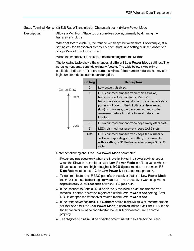
FGR Wireless Data Transceivers
LUM0047AA Rev B
Setup Terminal Menu: (3) Edit Radio Transmission Characteristics > (9) Low PowerMode
Description: Allows aMultiPoint Slave to consume less power, primarily by dimming thetransceiver's LEDs.
When set to 2 through 31, the transceiver sleeps between slots. For example, at asetting of 2 the transceiver sleeps 1 out of 2 slots; at a setting of 3 the transceiversleeps 2 out of 3 slots, and so on.
When the transceiver is asleep, it hears nothing from theMaster.
The following table shows the changes at different Low Power Mode settings. Theactual current draw depends onmany factors. The table below gives only aqualitative indication of supply current savings. A low number reduces latency and ahigh number reduces current consumption.
Setting Description0 Low power, disabled.
1 LEDs dimmed, transceiver remains awake,transceiver is listening to theMaster’stransmissions on every slot, and transceiver’s dataport is shut down if the RTS line is de-asserted(low). In this case, the transceiver needs to beawakened before it is able to send data to theMaster.
2 LEDs dimmed, transceiver sleeps every other slot.
3 LEDs dimmed, transceiver sleeps 2 of 3 slots.
4-31 LEDs dimmed, transceiver sleeps the number ofslots corresponding to the setting. For example,with a setting of 31 the transceiver sleeps 30 of 31slots.
Note the following about the Low Power Mode parameter:
l Power savings occur only when the Slave is linked. No power savings occurwhen the Slave is transmitting data. Low Power Mode is of little value when aSlave has a constant, high throughput.MCU Speedmust be set to 0 andRFData Ratemust be set to 3 for Low Power Mode to operate properly.
l To communicate to an RS232 port of a transceiver that is in Low Power Mode,the RTS linemust be held high to wake it up. The transceiver wakes up withinapproximately 20milliseconds of when RTS goes high.
l If the Request to Send (RTS) line on the Slave is held high, the transceiverremains in normal operation regardless of the Low Power Mode setting. AfterRTS is dropped the transceiver reverts to the Low Power Mode.
l If the transceiver has theDTR Connect option In theMultiPoint Parameters tabset to 1 or 2 and if the Low Power Mode is enabled (set to 1-31), the RTS line onthe transceiver must be asserted for theDTR Connect feature to operateproperly.
l The diagnostic pins must be disabled or terminated to a cable for the Sleep
55

Chapter 3: Configuring Point-to-MultiPoint Networks
LUM0047AA Rev B
current in Lower PowerMode tomatch the specifications. To disable thediagnostic pins, ensure the following are set:
l In the Baud Rate tab, theSetup Port parameter is set to 1 (MainOnly).
l In theMultiPoint Parameters tab, theDiagnostics parameter is set to0 (Off).
l To realize full power savings in Low Power Mode, the serial port must bedeactivated between operation. To do that the RTS linemust be asserted.However, because RS485/422 operation uses the RTS line as part of the databus, it cannot be asserted to wake-up the radio. Therefore, FreeWaverecommends that all radios set to RS485 or RS422, use a Low Power Modeof 0.
Reading Diagnostics in Tool SuiteThe Network Diagnostics application provides a place to view diagnostic data for all the devices connected totheMaster in your network in real time. This application is not meant to replicate the functionality of an NMSsystem, but rather it is a tool that can be used for diagnostics and troubleshooting in the field.
Important: The Network Diagnostics application is intended for occasional networkmonitoring or troubleshooting, not for continuous, long-term collection of diagnosticdata.
This section provides basic steps for reading diagnostics using Tool Suite. Tool Suite stores the diagnosticdata in the database and you can import or export a diagnostic file. For information regarding the dataavailable, recommended best practices, and importing and exporting files using the Network Diagnosticsapplication, see the Tool Suite User Manual available on theUserManual and System Tools CD or byselecting File > Help in the Tool Suite software.
Note: To help identify the transceivers in your network when running NetworkDiagnostics, set theRadio Name andRadio ID fields in theMultiPointParameters tab.
The diagnostic programmust be run from theMaster transceiver. Diagnostics requires the following:
l A setting of this parameter on theMaster between 1 and 128.
l A second computer or serial connection to run the diagnostics software.
l A diagnostics cable. (Available from FreeWave.)
l Diagnostics software. (Available on theUserManual and System Tools CD and onwww.freewave.com.)
For more information about Diagnostics, contact FreeWave Technical Support.
To run diagnostics using Tool Suite:
1. Connect theMaster to the computer running Tool Suite.
2. Open Tool Suite and click Network Diagnostics in the Applications pane.
56

FGR Wireless Data Transceivers
LUM0047AA Rev B
3. From the drop-downmenu in the Networks section of the ribbon, select the serial network forwhich you want to run diagnostics.
If you do not have a network defined, click Add and follow the instructions in the wizard. For moreinformation, see the Tool Suite User's Manual.
4. From the ribbon, click Start.
5. To stop running diagnostics, click Stop.
If youmove away from the Network Diagnostics application without selectingStop, the programcontinues to poll for diagnostic data.
Important: Tool Suite is not optimized for the collection andmanagement of largeamounts of diagnostic data from continuous polling. Collection of excessive amountsof data results in overall performance degradation in Tool Suite and network throughputdegradation.
57

LUM0047AA Rev B 58
LUM0047AA Rev B
Chapter 4: ConfiguringPoint-to-Point Networks
Point-to-Point networks are themost basic type of network, and do not require muchmore than setting up thebasic network, as described in the basic programming and setup chapter.
This chapter provides:
l A brief quick start to setup a Point-to-Point network.
l An LED chart for LED function within a Point-to-Point network.
l Information about programming the Call Book.
Point-to-Point Network Quick StartTo establish communications between a pair of FreeWave transceivers just received from the factory,complete the steps described below for each transceiver.
Point-to-Point Network Quick Start (Tool Suite):
1. Connect the transceiver to the serial port of a computer either through a serial cable or via thediagnostics cable. Make sure to connect the radio to a power source.
Power supply ranges and recommendations vary depending onmodel. Verify the specifications forthemodel you are using prior to connecting power.
2. Open a Tool Suite session, select theConfiguration application, and ensure the correct port isselected in theCom Port field in the Configuration ribbon.
3. From the Networks section of the Configuration ribbon, select the network in which the radioresides or click Add Network to create a new network in Tool Suite.
4. Click Read Radio in the Configuration ribbon to read the radio's current settings.
59

Chapter 4: Configuring Point-to-Point Networks
LUM0047AA Rev B
l If you are using a diagnostics cable to connect to the radio, the radio automatically goes intoSetupmode.
l If you are using a data cable to connect to the radio, you are prompted to press the radio'sSetup button to put the radio in Setupmode.
l When in Setupmode, all three LEDs on the radio display solid green.
5. Select the OperationMode tab.
In theModem Mode field, select to set the radio in Point-to-Point mode. For example, set oneradio as a Point-to-Point Master (Mode 0) and the other as a Point-to-Point Slave (Mode 1). Formore information about modemmodes, see "Setting the Transceiver's Role in the Network and theNetwork Type" on page 19.
Note: A network can have only oneMaster.
6. Select the Baud Rate tab.
Change theBaud Rate, Data Parity, andModbus RTU to match the device that the radio is to beattached to.
7. Select the Transmission Characteristics tab.
Set the following parameters so they are identical on all radios in the network:
l Frequency Key
l Max Packet Size
l Min Packet Size
l RF Data Rate
If several independent MultiPoint networks are located in close proximity, it becomes veryimportant to include as much frequency and time diversity as possible through use of differentFrequency Key,Min and Max Packet Size, andHop Table settings.
Changing these settings from the factory defaults may help to eliminate interference from otherFreeWave networks.
8. Select the Call Book tab.
Enter the Slave serial number in theMaster’s Call Book. Enter theMaster’s Serial number in theSlave’s Call Book, or disable Slave Security (in the Slave). For more information about setting upthe Call Book see "Using the Call Book in Point-to-Point Networks" on page 62.
Shortly after both transceivers are plugged in, they should establish a communications link witheach other and the connection is complete. Using the table below, verify that the radios areoperating as expected.
Point-to-Point Network Quick Start (Terminal Interface):
1. Connect antennas to the transceivers.
2. Connect the transceiver to the serial port of a computer either through a serial cable or via thediagnostics cable. Make sure to connect the radio to a power source.
Power supply ranges and recommendations vary depending onmodel. Verify the specifications forthemodel you are using prior to connecting power.
60

FGR Wireless Data Transceivers
LUM0047AA Rev B
3. Open a terminal emulator session and use the following settings in connecting the radio. You canalso use Setup Terminal within Tool Suite if a terminal emulator is unavailable.
l Connect to COMx (where 'x' is the number of the port being connected).
l Set the following:
l Data Rate - 19,200
l Data Bits - 8
l Parity - none
l Stop bits - 1
l Flow control - none
4. Press theSetup button on the radio. If using the diagnostics cable, press Shift-U (capital U).
l The three LEDs on the radio should all turn green, indicating Setupmode.
l TheMainmenu displays on the screen.
5. Press 0 to access the OperationModemenu.
l Press0 to set the radio as a Point-to-Point Master or press 1 to set the radio as Point-to-Pointslave. For more information about modemmodes, see "Setting the Transceiver's Role in theNetwork and the Network Type" on page 19.
l Press Esc to return to theMainmenu.
6. Press 1 in theMainmenu.
l Change theBaud Rate, Data Parity, andModbus RTU to match the device that the radio isto be attached to.
l Press Esc to return to theMainmenu.
7. Press 2 in theMainmenu to update the Call Book.
Enter the Slave serial number in theMaster’s Call Book. Enter theMaster’s Serial number in theSlave’s Call Book, or disable Slave Security (in the Slave). For more information about setting upthe Call Book, see "Using the Call Book in Point-to-Point Networks" on page 62.
8. Press 3 in theMainmenu.
l Set the following parameters so they are the same on all radios in the network:
l FreqKey
l Max Packet Size
l Min Packet Size
l RF Data Rate
The Frequency Key options is located in the F submenu after you press 0 to access the FrequencyKey menu inMainmenu 3.
Changing these values may help to eliminate interference from other FreeWave networks.
l Press Esc to return to theMainmenu.
61
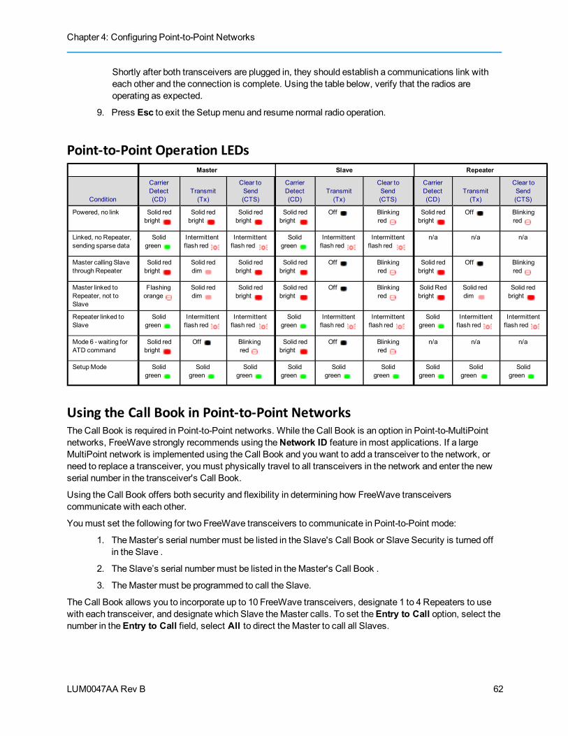
Chapter 4: Configuring Point-to-Point Networks
LUM0047AA Rev B
Shortly after both transceivers are plugged in, they should establish a communications link witheach other and the connection is complete. Using the table below, verify that the radios areoperating as expected.
9. Press Esc to exit the Setupmenu and resume normal radio operation.
Point-to-Point Operation LEDsMaster Slave Repeater
Condition
CarrierDetect(CD)
Transmit(Tx)
Clear toSend(CTS)
CarrierDetect(CD)
Transmit(Tx)
Clear toSend(CTS)
CarrierDetect(CD)
Transmit(Tx)
Clear toSend(CTS)
Powered, no link Solid redbright
Solid redbright
Solid redbright
Solid redbright
Off Blinkingred
Solid redbright
Off Blinkingred
Linked, no Repeater,sending sparse data
Solidgreen
Intermittentflash red
Intermittentflash red
Solidgreen
Intermittentflash red
Intermittentflash red
n/a n/a n/a
Master calling Slavethrough Repeater
Solid redbright
Solid reddim
Solid redbright
Solid redbright
Off Blinkingred
Solid redbright
Off Blinkingred
Master linked toRepeater, not toSlave
Flashingorange
Solid reddim
Solid redbright
Solid redbright
Off Blinkingred
Solid Redbright
Solid reddim
Solid redbright
Repeater linked toSlave
Solidgreen
Intermittentflash red
Intermittentflash red
Solidgreen
Intermittentflash red
Intermittentflash red
Solidgreen
Intermittentflash red
Intermittentflash red
Mode 6 - waiting forATD command
Solid redbright
Off Blinkingred
Solid redbright
Off Blinkingred
n/a n/a n/a
SetupMode Solidgreen
Solidgreen
Solidgreen
Solidgreen
Solidgreen
Solidgreen
Solidgreen
Solidgreen
Solidgreen
Using the Call Book in Point-to-Point NetworksThe Call Book is required in Point-to-Point networks. While the Call Book is an option in Point-to-MultiPointnetworks, FreeWave strongly recommends using theNetwork ID feature in most applications. If a largeMultiPoint network is implemented using the Call Book and you want to add a transceiver to the network, orneed to replace a transceiver, youmust physically travel to all transceivers in the network and enter the newserial number in the transceiver's Call Book.
Using the Call Book offers both security and flexibility in determining how FreeWave transceiverscommunicate with each other.
Youmust set the following for two FreeWave transceivers to communicate in Point-to-Point mode:
1. TheMaster’s serial numbermust be listed in the Slave's Call Book or Slave Security is turned offin the Slave .
2. The Slave’s serial numbermust be listed in theMaster's Call Book .
3. TheMaster must be programmed to call the Slave.
The Call Book allows you to incorporate up to 10 FreeWave transceivers, designate 1 to 4 Repeaters to usewith each transceiver, and designate which Slave theMaster calls. To set theEntry to Call option, select thenumber in theEntry to Call field, select All to direct theMaster to call all Slaves.
62
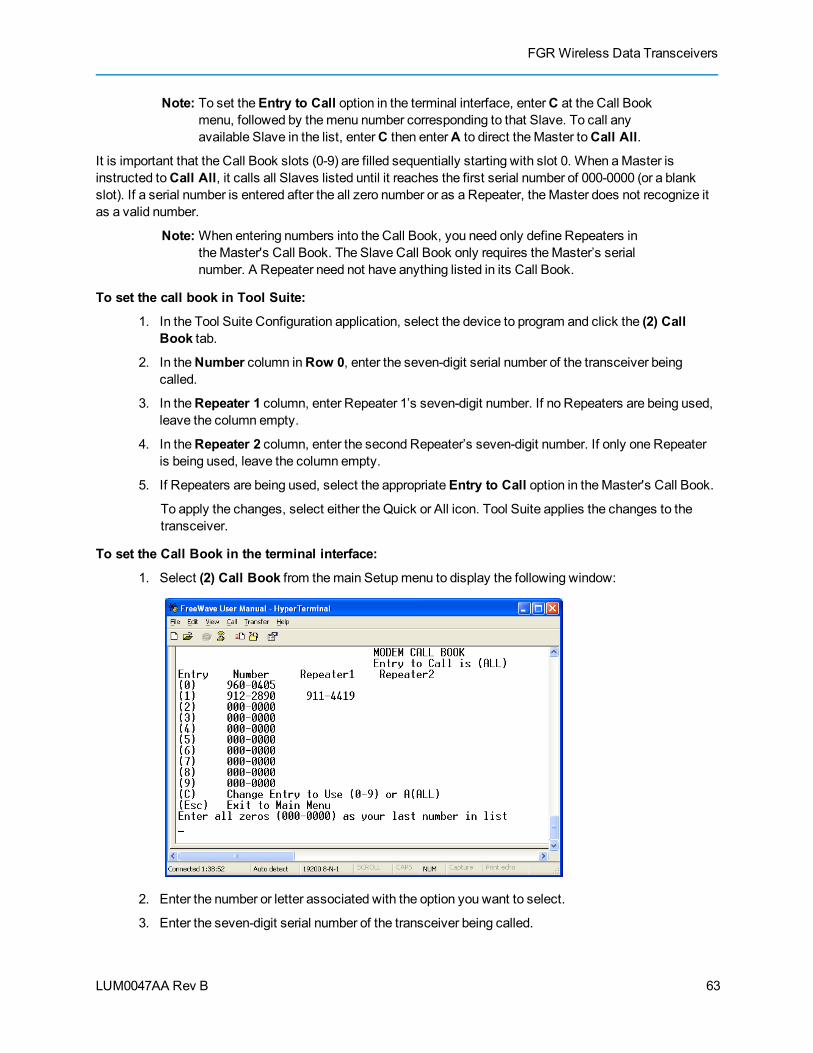
FGR Wireless Data Transceivers
LUM0047AA Rev B
Note: To set theEntry to Call option in the terminal interface, enterC at the Call Bookmenu, followed by themenu number corresponding to that Slave. To call anyavailable Slave in the list, enterC then enterA to direct theMaster toCall All.
It is important that the Call Book slots (0-9) are filled sequentially starting with slot 0. When aMaster isinstructed toCall All, it calls all Slaves listed until it reaches the first serial number of 000-0000 (or a blankslot). If a serial number is entered after the all zero number or as a Repeater, theMaster does not recognize itas a valid number.
Note:When entering numbers into the Call Book, you need only define Repeaters intheMaster's Call Book. The Slave Call Book only requires theMaster’s serialnumber. A Repeater need not have anything listed in its Call Book.
To set the call book in Tool Suite:
1. In the Tool Suite Configuration application, select the device to program and click the (2) CallBook tab.
2. In theNumber column inRow 0, enter the seven-digit serial number of the transceiver beingcalled.
3. In theRepeater 1 column, enter Repeater 1’s seven-digit number. If no Repeaters are being used,leave the column empty.
4. In theRepeater 2 column, enter the second Repeater’s seven-digit number. If only one Repeateris being used, leave the column empty.
5. If Repeaters are being used, select the appropriateEntry to Call option in theMaster's Call Book.
To apply the changes, select either the Quick or All icon. Tool Suite applies the changes to thetransceiver.
To set the Call Book in the terminal interface:
1. Select (2) Call Book from themain Setupmenu to display the following window:
2. Enter the number or letter associated with the option you want to select.
3. Enter the seven-digit serial number of the transceiver being called.
63
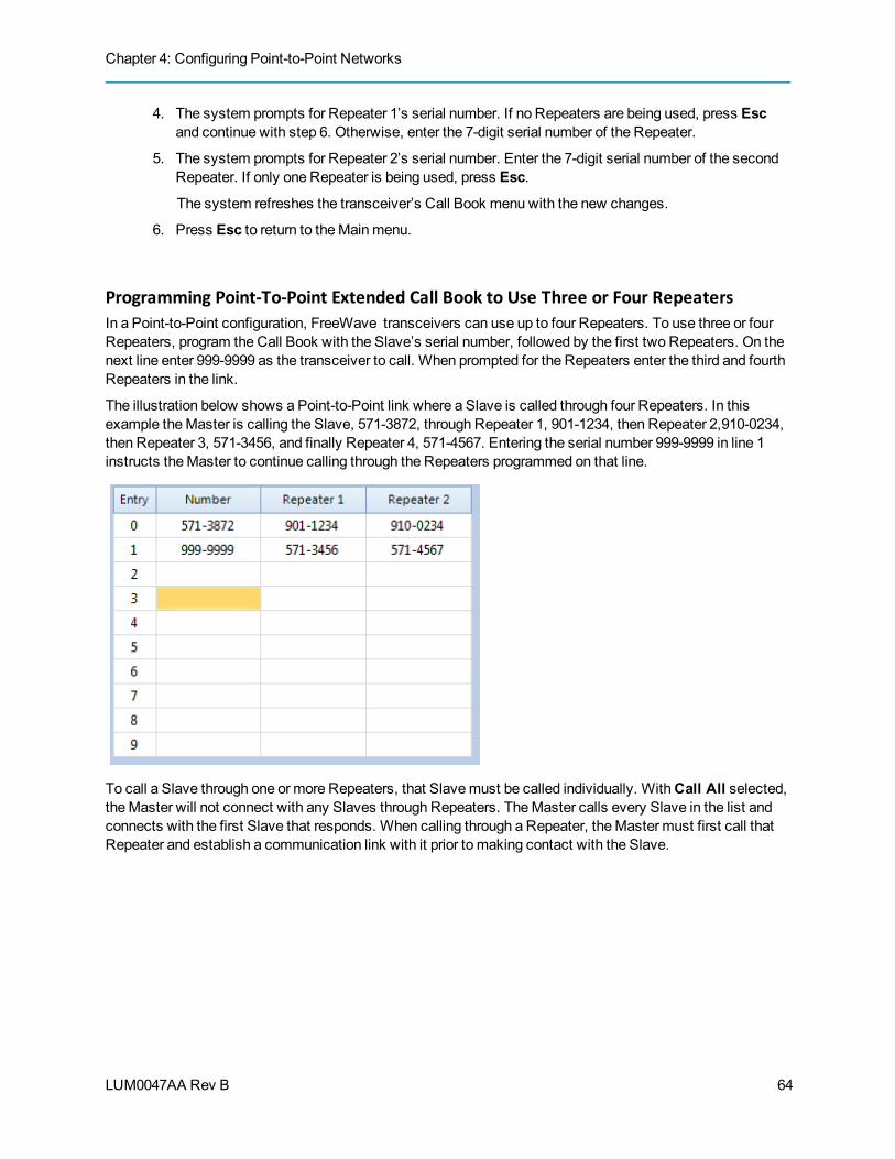
Chapter 4: Configuring Point-to-Point Networks
LUM0047AA Rev B
4. The system prompts for Repeater 1’s serial number. If no Repeaters are being used, press Escand continue with step 6. Otherwise, enter the 7-digit serial number of the Repeater.
5. The system prompts for Repeater 2’s serial number. Enter the 7-digit serial number of the secondRepeater. If only one Repeater is being used, press Esc.
The system refreshes the transceiver’s Call Book menu with the new changes.
6. Press Esc to return to theMainmenu.
Programming Point-To-Point Extended Call Book to Use Three or Four RepeatersIn a Point-to-Point configuration, FreeWave transceivers can use up to four Repeaters. To use three or fourRepeaters, program the Call Book with the Slave’s serial number, followed by the first two Repeaters. On thenext line enter 999-9999 as the transceiver to call. When prompted for the Repeaters enter the third and fourthRepeaters in the link.
The illustration below shows a Point-to-Point link where a Slave is called through four Repeaters. In thisexample theMaster is calling the Slave, 571-3872, through Repeater 1, 901-1234, then Repeater 2,910-0234,then Repeater 3, 571-3456, and finally Repeater 4, 571-4567. Entering the serial number 999-9999 in line 1instructs theMaster to continue calling through the Repeaters programmed on that line.
To call a Slave through one or more Repeaters, that Slavemust be called individually. WithCall All selected,theMaster will not connect with any Slaves through Repeaters. TheMaster calls every Slave in the list andconnects with the first Slave that responds. When calling through a Repeater, theMaster must first call thatRepeater and establish a communication link with it prior to making contact with the Slave.
64

LUM0047AA Rev B
Chapter 5: Advanced Programming
The settings and scenarios covered in this chapter are considered advanced programming, and are settingsand scenarios that you are not as likely to use in your network.
Working with Parallel RepeatersAs you add Repeaters to your network, plan accordingly do avoid creating a parallel Repeater scenario. Aparallel Repeater is defined as two or more Repeaters linked to the same point in the network.
65

Chapter 5: Advanced Programming
LUM0047AA Rev B
The Slave in themiddle has overlapping coverage from both the Repeaters (parallel Repeaters). Data from theRepeaters is transmitted on the same Frequency Key in the same time slot, which creates messagecollisions.
To resolve this scenario, change the following settings on one or more of the Repeaters in conflict:
l Repeater Frequency - Set theRepeater Frequency parameter in theMultiPoint Parameters tabto any number other than 0. If set to a number other than 0, the transceiver uses the frequency keyset in the Frequency Key parameter in the Transmission Characteristics tab, instead of the keyassigned to theMaster.
l Frequency Key - Set the Frequency Key parameter in the Transmission Characteristics tab to akey other than that of the conflicting Repeater.
If you need to add a Repeater to your network, use the following steps to help ensure that you resolve anyparallel Repeater issues up front, before deploying the Repeater in the network.
1. From within Tool Suite, run a network diagnostics file. You can also gather the settings from all theRepeaters that are currently in your network.
2. Review the network diagnostics file, paying special attention to the following settings on eachRepeater and theMaster
l Frequency Key
l Repeater Frequency
l Rx and Tx Subnet IDs
66

FGR Wireless Data Transceivers
LUM0047AA Rev B
3. On a piece of paper, draw your network, noting the above settings for each Repeater, ensuringthere are no duplicates.
If there are duplicates, change the Repeater Frequency and the Frequency Key parameters asdescribed above.
If the Repeater you are adding is the only Repeater in the network, set the Frequency Key tomatch theMaster, theRx Subnet ID to match theMaster's Tx Subnet ID setting, and the TxSubnet ID to 1. In theMaster, set theRepeaters parameter toEnabled.
Setting Transceiver PasswordsUse passwords to prevent access to or changing of any of the transceiver’s parameters. This option is usefulif you want to prevent unauthorized personnel from gaining access to the transceiver settings.
If theSetup Port option in the Baud Rate tab is set to (1) Main Only or (3) Both, the password is onlyaccepted if the option is accessed from themain data port. To use the Password function using thediagnostics port, theSetup Port optionmust be set to (2) Diagnostics Only.
Warning! If the password feature is enabled and the password is forgotten, you needto return the transceiver to FreeWave to have the password disabled.
To set a password:
1. From the Setupmainmenu in the terminal interface, select (8) Chg Password to display thefollowing prompt:
New PW? (<esc> to exit)
2. To back out of the process and not enable the password press Esc. To set a password, typeexactly four characters. Passwords are case sensitive.
Press Esc to cancel the process at any point.
3. After you enter the four characters the following prompt displays:
<Enter> to accept,<esc> to quit.
4. To accept the password as entered and enable the feature, press Enter. To quit the process andnot enable the password, press Esc.
If you press Enter, the password displays on the line above. The password is case sensitive andevery keystroke is a character.
To change a password:
After the password feature has been enabled, it is possible to change to a new password.
1. From the Setupmainmenu in the terminal interface, select (8) Chg Password.
2. At the Enter Security Code prompt enter the current four character, case sensitive password.
After entering the password correctly, the prompt to enter the new password displays. Enter thenew four character, case sensitive password.
Press Esc to cancel this process at any point.
3. To accept the password as entered and enable the feature, press Enter. To quit the process andnot enable the password, press Esc.
67
Chapter 5: Advanced Programming
LUM0047AA Rev B
If you press Enter, the password displays on the line above. The password is case sensitive andevery keystroke is a character.
To disable a password:
After the password features has been enabled, it is possible to disable the password if you know the currentpassword.
Important: You can only disable a password using the prompt when you read the radioin Tool Suite, or through a terminal emulator. You cannot disable the password usingSetup Terminal within Tool Suite.
1. From the Setupmainmenu in the terminal interface, select (8) Chg Password.
2. Hold down theAlt key and type 0255 using the number pad on your keyboard and release theAltkey.
3. Repeat this step threemore times (holdAlt and type 0255 a total of 4 times).
Important: Youmust type the 0255 using the NUM Pad on your computer, not the toprow of numerals.
After the fourth entry, the password is disabled.
Low Baud RatesThe transceiver's baud ratemay be set to 300, 600, or 900 baud. For more information about using a low baudrate, contact FreeWave technical support.
Multi-Master SynchTheMulti-Master Synch setting is reserved for applications, in both Point-to-Point andMultiPoint modes,with concentrations of Master units where it is necessary to reduce interference between theMasters. Formore information, see application note #5412, Synchronizing CollocatedMasters, or contact FreeWaveTechnical Support.
Time Divisible Multiple Access (TDMA)Available in some transceiver models, the FreeWave TimeDivisionMultiple Access (TDMA) protocol is anenhanced and sophisticated version of Point-to-MultiPoint communications. The TDMA protocol providestiming and other parameters, which in turn allow large transceiver networks to work in a non-polledenvironment.
This option is only used for peer-to-peer communications or when applications are very time specific. Foradditional information about TDMA, contact FreeWave Technical Support.
68
LUM0047AA Rev B
Chapter 6: Viewing Radio Statistics
When you read a radio the system displays data transmission statistics the transceiver has gathered duringthemost recent session. This information is valuable when you need to know the signal strength and noiselevels of the link. Statistics are gathered during each data link and are reset when the next link begins.
In addition, you can view more data transmission characteristics in the Network Diagnostics application. Forinformation about running network diagnostics using Tool Suite, see the Tool Suite User Manual.
To display the radio statistics in Tool Suite:
1. In the Tool Suite Configuration application, click Read Radio, and then click the DeviceInformation tab.
2. Review the radio characteristics. Each characteristic is described in detail in the sections below.
You can also view the same statistics using the Setup Terminal option in Tool Suite.
To display the Radio Transmission Characteristics in the terminal interface:
1. Select (4) Show Radio Statistics from the Setupmainmenu to display the following window:
Review the radio characteristics. Each characteristic is described in detail in the sections below.
Antenna Reflected PowerThis is ameasurement of the transmitted power that is reflected back into the transceiver frommismatchedantennas or cables, or loose connections between the transceiver and antenna. A reading of 0 to 5 is good; 5to 20 is marginal; 20 or higher indicates that the connections should be inspected for loose connections andcable quality. A reading of 30 or higher indicates a definite problem in the system.
Themost likely reason for a higherAntenna Reflected Power reading is a cable issue between the radio andthe antenna: loose connections, cable kinks, breaks in cable shielding, moisture in the fittings or connections,
69
Chapter 6: Viewing Radio Statistics
LUM0047AA Rev B
etc. Less commonly, a highAntenna Reflected Power reading can indicate a hardware problem with theradio itself, such as a damaged RF connector. Lastly, a high readingmay indicate a problem with the antennaitself, although antenna problems are the least likely indicator.
Master-Slave DistanceThe physical distance between the slave radio and themaster radio in your network.This distance is mostaccurate at a distance greater than 2.5miles.
Noise LevelTheNoise Level indicates the level of background noise and interference at this transceiver and at each ofthe Repeaters in the link. The number is an average of the noise levels measured at each frequency in thetransceiver’s frequency hop table.
The individual measurement values at each frequency hop channel are shown in thefrequency table. If you are viewing statistics in the terminal interface, press Enterwhen the Radio Statistics menu displays to view the frequency table.
Ideally, the difference between the average signal level and average noise level should be 26or more. Noiselevels significantly higher than this are an indication of a high level of interference that may degrade theperformance of the link. High noise levels can often bemitigated with band pass filters, antenna placement orantenna polarization.
Number of DisconnectsAnytime the link between theMaster and the Slave is broken and the radios lose Carrier Detect.
The value indicates the total number of disconnects that have occurred from the time the transceiver ispowered on until the radio is put into Setupmode. Under ideal operating conditions, the number of disconnectsshould be 0. One or more disconnects may indicate a weak link, the presence of severe interference problemsor loss of power to any of the radios in the link.
Note: In Tool Suite, the disconnect information is available in the Summary View inthe Network Diagnostics application.
Radio TemperatureTheRadio Temperature value is the current operating temperature of the transceiver in degrees Celsius. Forproper operation, a FreeWave transceiver must be in the temperature range of -40° to +75° C. Some of thetransceivers are only tested to 0° C. See the transceiver specifications later in this document for details.
Rate %TheRate %measures the percentage of data packets that were successfully transmitted from theMaster tothe Slave on the first attempt. A number of 75 or higher indicates a robust link that provides very goodperformance even at high data transmission rates. A number of 15 or lower indicates a weak or marginal link
70

FGR Wireless Data Transceivers
LUM0047AA Rev B
that provides lower data throughput. A Rate % of 100% provides approximately 100 KBaud of bandwidth withanRF Data Rate setting of 3 and approximately 150 KBaud of bandwidth with anRF Data Rate of 2. Thesenumbers are reduced approximately 50% if one or more Repeaters are in the network.
Signal LevelTheSignal Level indicates the level of received signal at this transceiver and at each of the Repeaters in thelink. For each of these, the signal source is the transceiver that transmits to it. The number is an average ofthe received signal levels measured at each frequency in the transceiver's frequency hop table.
The individual measurement values at each frequency hop channel are shown in thefrequency table. If you are viewing statistics in the terminal interface, press Enterwhen the Radio Statistics menu displays to view the frequency table.
For a reliable link, themargin should be at least 26 dB. Low average signal levels can often be corrected withhigher gain antennas, better antenna placement and/or additional Repeaters.
Note: See the installationmanual for antenna and FCC requirements.
Transmit CurrentThe Transmit Currentmeasures the current draw of the transmitter in milliamps (mA). See the transceiverspecifications for typical values.
71

LUM0047AA Rev B 72

LUM0047AA Rev B
Chapter 7: Troubleshooting
If you are experiencing trouble with your network, use the following to initially troubleshoot and help identifythe problem with the network or a radio within it:
l LEDs on the radio. See "Point-to-MultiPoint Operation LEDs" on page 43 and "Point-to-PointOperation LEDs" on page 62.
l Radio Settings
l RFQuality
Use the following flow chart and the troubleshooting list in this chapter to walk through basic checks to helpdiagnose the issue. If you need assistance, contact FreeWave Technical Support.
73
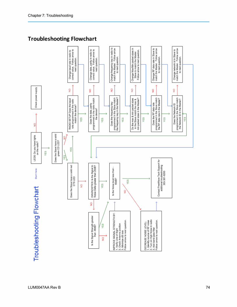
Chapter 7: Troubleshooting
LUM0047AA Rev B
Troubleshooting Flowchart
74
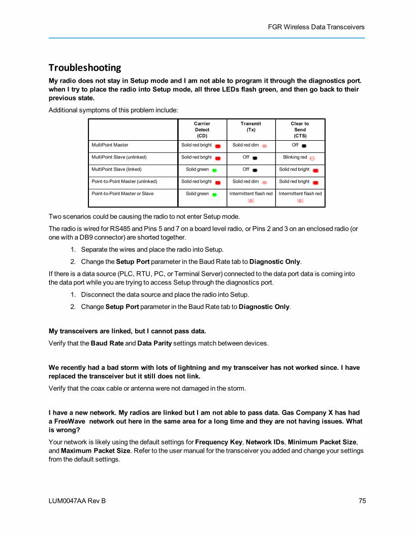
FGR Wireless Data Transceivers
LUM0047AA Rev B
TroubleshootingMy radio does not stay in Setup mode and I am not able to program it through the diagnostics port.when I try to place the radio into Setup mode, all three LEDs flash green, and then go back to theirprevious state.
Additional symptoms of this problem include:
CarrierDetect(CD)
Transmit(Tx)
Clear toSend(CTS)
MultiPoint Master Solid red bright Solid red dim Off
MultiPoint Slave (unlinked) Solid red bright Off Blinking red
MultiPoint Slave (linked) Solid green Off Solid red bright
Point-to-Point Master (unlinked) Solid red bright Solid red dim Solid red bright
Point-to-Point Master or Slave Solid green Intermittent flash red Intermittent flash red
Two scenarios could be causing the radio to not enter Setupmode.
The radio is wired for RS485 and Pins 5 and 7 on a board level radio, or Pins 2 and 3 on an enclosed radio (orone with a DB9 connector) are shorted together.
1. Separate the wires and place the radio into Setup.
2. Change theSetup Port parameter in the Baud Rate tab toDiagnostic Only.
If there is a data source (PLC, RTU, PC, or Terminal Server) connected to the data port data is coming intothe data port while you are trying to access Setup through the diagnostics port.
1. Disconnect the data source and place the radio into Setup.
2. ChangeSetup Port parameter in the Baud Rate tab toDiagnostic Only.
My transceivers are linked, but I cannot pass data.
Verify that theBaud Rate andData Parity settings match between devices.
We recently had a bad storm with lots of lightning and my transceiver has not worked since. I havereplaced the transceiver but it still does not link.
Verify that the coax cable or antenna were not damaged in the storm.
I have a new network. My radios are linked but I am not able to pass data. Gas Company X has hada FreeWave network out here in the same area for a long time and they are not having issues. Whatis wrong?
Your network is likely using the default settings for Frequency Key, Network IDs,Minimum Packet Size,andMaximum Packet Size. Refer to the user manual for the transceiver you added and change your settingsfrom the default settings.
75
Chapter 7: Troubleshooting
LUM0047AA Rev B
Most of my sites report in and I can poll, but I cannot poll any of the Slaves that talk back toRepeater 2.
Repeater 2 is experiencing high noise.
My network has been running flawlessly for the last 2 years. Now, all of a sudden, I have a group ofSlaves that I cannot poll.
A Parallel Repeater has been added/changed in the network and has the same frequency settings and is nowinterfering with the other Repeater. Program the new Repeater with a different set of parameters.
My network keeps locking up. If I cycle power on the Master, the network is restored and I can pollagain until the next time the network locks up.
There is a "chatty" Slave in the network. The Slave is not getting acknowledgement of data it sends to theMaster and it keeps trying to resend data to theMaster locking out all other communications to theMaster.This is typically caused by a bad signal from the Slave to theMaster. Verify line of sight, antenna direction,and noise levels at the Slave.
I installed a new Slave in my network, but I cannot get it to link. The CD light is solid red and theCTS light is blinking red.
LOS (Line of Sight) issue or settings issue.
I have a site that used to perform flawlessly. Now I cannot reliably get data from the RTU at this site.
Antenna reflected power causing problem. Reflected powermay be caused by defects or damage in theantenna, cabling, connections, etc. Verify that the cabling, connectors, and the antenna are connectedcorrectly and have not sustained any damage.
When I connect directly to my RTU I am able to poll data successfully. When I add in thetransceivers, I cannot get any data from my poll.
Baud rate above 38,400may need flow control line connected.
My Master is receiving odd or incorrect data after a poll request.
There is a serial interfacemismatch between the site, the device, or the radio.
1. From within Tool Suite, save a network diagnostic file for your network.
2. Scan the file for serial radios whoseSerial Interface parameter is set toRS232.
3. For the RS232 radios, look at the Data TX information in the summary view for any radio that hasan excessively high Data TX.
You are looking for one or more sites that increase the data count by the number of bytescontained in the poll request. For example, if a poll is 64 bytes, the data poll increases by 64 bytesafter the poll.
76
FGR Wireless Data Transceivers
LUM0047AA Rev B
4. The sites you identify may be configured as RS232, but wired as RS485. Send a technician to thesite to verify the wiring.
5. If the site is wired for RS485 and the device connected to the radio is an RS485 device, correct thefollowing parameter settings in the Baud Rate tab and send the new settings to the radio:
l Serial Interface - Set toRS485 .
l Setup Port - Set toDiagnostics Only.
l Modbus RTU - Set to 1.
l Turn Off Delay - Set to 4.
If the site is wired for RS485 and device connected requires RS232, correct the wiring from theradio to the device.
l Pin 5 on the FreeWave radio to device RX.
l Pin 7 on the FreeWave radio to device TX.
l Pin 6 on the FreeWave radio to device signal ground.
77

LUM0047AA Rev B 78

LUM0047AA Rev B
Chapter 8: Additional Transceiver Information
This section contains additional important information about the FreeWave transceivers described in thismanual.
l Operational RS422 and RS485 information
l Connector pin assignments
l FGROOEM board pin assignments
l FGR-115WC Waterproof Enclosure pin assignments for 11-pinWaterproof cable, partASC0612WW.
l Factory default settings
l Specifications
l Mechanical drawings
Operational RS422 and RS485 InformationFor RS422 and RS485, the FreeWave transceiver can drive 32 standard unit loads and loads the bus with only1/8 unit load. This means you can tie up to 256 devices on the bus if all of the line receivers have 1/8 unit load.
RS422 is used for 4-wire or full duplex communication with oneMaster andmultiple Slaves. The FreeWaveMaster transceiver keeps the line driver asserted at all times. Themaximum line length is 4,000 feet using 2,120 ohm twisted pair cables with a 5th wire for data common.
RS485 full duplex using 4 wire plus common is the same as RS422, except the system can havemultipleMasters on the bus.
79
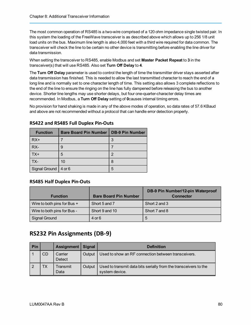
Chapter 8: Additional Transceiver Information
LUM0047AA Rev B
Themost common operation of RS485 is a two-wire comprised of a 120 ohm impedance single twisted pair. Inthis system the loading of the FreeWave transceiver is as described above which allows up to 256 1/8 unitload units on the bus. Maximum line length is also 4,000 feet with a third wire required for data common. Thetransceiver will check the line to be certain no other device is transmitting before enabling the line driver fordata transmission.
When setting the transceiver to RS485, enableModbus and setMaster Packet Repeat to 3 in thetransceiver(s) that will use RS485. Also set Turn Off Delay to 4.
The Turn Off Delay parameter is used to control the length of time the transmitter driver stays asserted afterdata transmission has finished. This is needed to allow the last transmitted character to reach the end of along line and is normally set to one character length of time. This setting also allows 3 complete reflections tothe end of the line to ensure the ringing on the line has fully dampened before releasing the bus to anotherdevice. Shorter line lengths may use shorter delays, but four one-quarter-character delay times arerecommended. In Modbus, a Turn Off Delay setting of 0causes internal timing errors.
No provision for hand shaking is made in any of the abovemodes of operation, so data rates of 57.6 KBaudand above are not recommended without a protocol that can handle error detection properly.
RS422 and RS485 Full Duplex Pin-Outs
Function Bare Board Pin Number DB-9 Pin Number
RX+ 7 3
RX- 9 7
TX+ 5 2
TX- 10 8
Signal Ground 4 or 6 5
RS485 Half Duplex Pin-Outs
Function Bare Board Pin NumberDB-9 Pin Number/12-pin Waterproof
Connector
Wire to both pins for Bus + Short 5 and 7 Short 2 and 3
Wire to both pins for Bus - Short 9 and 10 Short 7 and 8
Signal Ground 4 or 6 5
RS232 Pin Assignments (DB-9)
Pin Assignment Signal Definition
1 CD CarrierDetect
Output Used to show anRF connection between transceivers.
2 TX TransmitData
Output Used to transmit data bits serially from the transceivers to thesystem device.
80
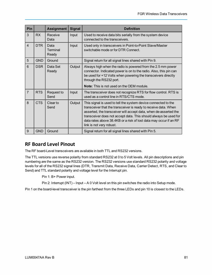
FGR Wireless Data Transceivers
LUM0047AA Rev B
Pin Assignment Signal Definition
3 RX ReceiveData
Input Used to receive data bits serially from the system deviceconnected to the transceivers.
4 DTR DataTerminalReady
Input Used only in transceivers in Point-to-Point Slave/Masterswitchable mode or for DTR Connect.
5 GND Ground Signal return for all signal lines shared with Pin 9.
6 DSR Data SetReady
Output Always high when the radio is powered from the 2.5mm powerconnector. Indicated power is on to the radio. Also, this pin canbe used for +12 Volts when powering the transceivers directlythrough the RS232 port.
Note: This is not used on theOEMmodule.
7 RTS Request toSend
Input The transceiver does not recognize RTS for flow control. RTS isused as a control line in RTS/CTS mode.
8 CTS Clear toSend
Output This signal is used to tell the system device connected to thetransceiver that the transceiver is ready to receive data. Whenasserted, the transceiver will accept data, when de-asserted thetransceiver does not accept data. This should always be used fordata rates above 38.4KB or a risk of lost datamay occur if an RFlink is not very robust.
9 GND Ground Signal return for all signal lines shared with Pin 5.
RF Board Level PinoutThe RF board-Level transceivers are available in both TTL and RS232 versions.
The TTL versions use reverse polarity from standard RS232 at 0 to 5 Volt levels. All pin descriptions and pinnumbering are the same as the RS232 version. The RS232 versions use standard RS232 polarity and voltagelevels for all of the RS232 signal lines (DTR, Transmit Data, Receive Data, Carrier Detect, RTS, and Clear toSend) and TTL standard polarity and voltage level for the Interrupt pin.
Pin 1: B+ Power input.
Pin 2: Interrupt (INT) – Input – A 0 Volt level on this pin switches the radio into Setupmode.
Pin 1 on the board-level transceiver is the pin farthest from the three LEDs and pin 10 is closest to the LEDs.
81
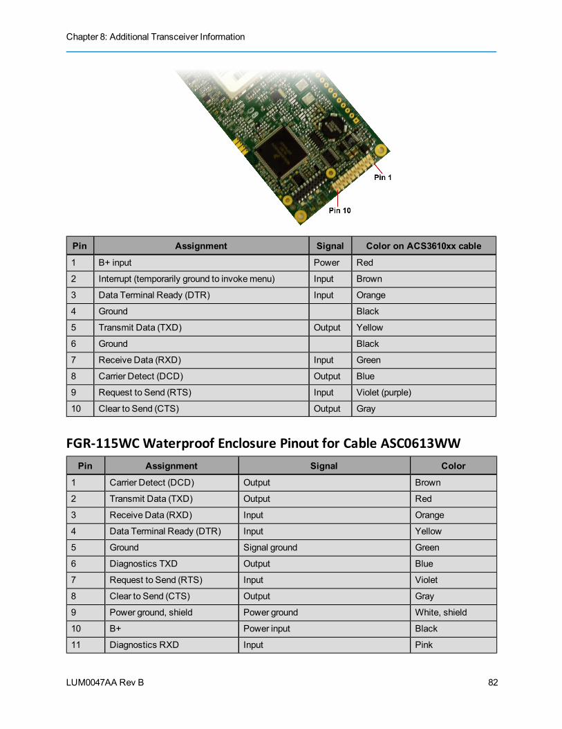
Chapter 8: Additional Transceiver Information
LUM0047AA Rev B
Pin Assignment Signal Color on ACS3610xx cable
1 B+ input Power Red
2 Interrupt (temporarily ground to invokemenu) Input Brown
3 Data Terminal Ready (DTR) Input Orange
4 Ground Black
5 Transmit Data (TXD) Output Yellow
6 Ground Black
7 Receive Data (RXD) Input Green
8 Carrier Detect (DCD) Output Blue
9 Request to Send (RTS) Input Violet (purple)
10 Clear to Send (CTS) Output Gray
FGR-115WCWaterproof Enclosure Pinout for Cable ASC0613WWPin Assignment Signal Color
1 Carrier Detect (DCD) Output Brown
2 Transmit Data (TXD) Output Red
3 Receive Data (RXD) Input Orange
4 Data Terminal Ready (DTR) Input Yellow
5 Ground Signal ground Green
6 Diagnostics TXD Output Blue
7 Request to Send (RTS) Input Violet
8 Clear to Send (CTS) Output Gray
9 Power ground, shield Power ground White, shield
10 B+ Power input Black
11 Diagnostics RXD Input Pink
82

FGR Wireless Data Transceivers
LUM0047AA Rev B
The following diagram illustrates the pin orientation for the waterproof connector:
83

Chapter 8: Additional Transceiver Information
LUM0047AA Rev B
FGRO9-CA, FGRO9-CSU, and FGRO9-TSU Transceiver SpecificationsSpecifications may change at any time without notice. For themost up-to-date specifications information, seethe product's data sheet available at www.freewave.com.
Specification
Frequency 902 to 928MHz
Transmitter
Output Power 5mW to 1W (+30 dBm) See RF transmit power settings, p. 1.
Range 60miles Line Of Sight, 0 dB antenna gain
Modulation 2 levelGFSK, 115.2 Kbpsor 153.6 Kbps
Occupied Bandwidth 230 kHz
Hopping Patterns 15 per Band, 105 total, user selectable
Hopping Channels 50 to 112, user selectable
Hopping Bands 7, user selectable
FrequencyZones 16 Zones, 7 Channels per zone
RF Connector Type SMA, TNC-Enclosed version only (Female connectors), no RF
Receiver
Sensitivity -110 dBm at 10-4 bit error rate; -108 dBm at 10-6 bit error rate
IFSelectivity 20 dB at fc ± 230 kHz
RF Selectivity 50 dB at 896MHz, 935MHz
Dynamic range +10 DBm 3rdOrder Intercept Point at Input Connector
Data Transmission
Error Detection 32 bit CRC, retransmit on error
Data Encryption Proprietary spread spectrum technology
LinkThroughput 115.2 KbpsStandard Speed; 80 HbpsLow Speed
*Uncompressed, measured assuming 75%frequencyavailability.
Data Interface Serial
Protocol RS232/RS485/422, 1200 Baud to 115.2 Baud
Data Connector Board Level: 10-pin header with locking ramp, 0.1 spacing, power/data connector
Encolsed (ruggedized): DB9
Power Requirements
Operating Voltage +6.5 to +30 VDC
84

FGR Wireless Data Transceivers
LUM0047AA Rev B
Specification
Current Mode +6.5 VDC +12 VDC +30 VDCTransmit 1 A 500mA 200mAReceive 152mA 86mA 43mA
Idle 40mA 21mA 12mASleep 8mA 6mA 3mA
Transmit is at 1Wpower at 100%duty cycle
General Information
Operating Temperature Range -40° C- +75° C (-40° F to +167°F)
Dimensions Board Level: 136mm L x62mmWx14mmH
Enclosed: 173mm L x107mmWx35mmH
Weight Board Level: 60 g
Enclosed: 390 g
Humidity 0 to 95%humidity non-condensing
85
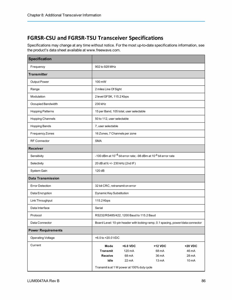
Chapter 8: Additional Transceiver Information
LUM0047AA Rev B
FGRSR-CSU and FGRSR-TSU Transceiver SpecificationsSpecifications may change at any time without notice. For themost up-to-date specifications information, seethe product's data sheet available at www.freewave.com.
Specification
Frequency 902 to 928MHz
Transmitter
Output Power 100mW
Range 2miles Line Of Sight
Modulation 2 levelGFSK, 115.2 Kbps
Occupied Bandwidth 230 kHz
Hopping Patterns 15 per Band, 105 total, user selectable
Hopping Channels 50 to 112, user selectable
Hopping Bands 7, user selectable
FrequencyZones 16 Zones, 7 Channels per zone
RF Connector SMA
Receiver
Sensitivity -100 dBm at 10-4 bit error rate; -98 dBm at 10-6 bit error rate
Selectivity 20 dB at fc +/- 230 kHz (2nd IF)
SystemGain 120 dB
Data Transmission
Error Detection 32 bit CRC, retransmit on error
Data Encryption DynamicKeySubstitution
LinkThroughput 115.2 Kbps
Data Interface Serial
Protocol RS232/RS485/422, 1200 Baud to 115.2 Baud
Data Connector Board Level: 10-pin header with locking ramp, 0.1 spacing, power/data connector
Power Requirements
Operating Voltage +6.0 to +20.0 VDC
Current Mode +6.0 VDC +12 VDC +20 VDCTransmit 120mA 68mA 46mAReceive 68mA 36mA 28mA
Idle 22mA 13mA 10mA
Transmit is at 1Wpower at 100%duty cycle
86

FGR Wireless Data Transceivers
LUM0047AA Rev B
Specification
General Information
Operating Temperature Range -40° C- +75° C (-40° F to +167°F)
Dimensions 127mmL x61mmWx16mmH
Weight 50 g
Humidity 0 to 95%humidity non-condensing
87

Chapter 8: Additional Transceiver Information
LUM0047AA Rev B
FGR-115RC and FGR-115WC Transceiver SpecificationsSpecifications may change at any time without notice. For themost up-to-date specifications information, seethe product's data sheet available at www.freewave.com.
Specification
Frequency 902 to 928MHz
Transmitter
Output Power 5mW to 1W
Range 60miles Line Of Sight
Modulation 2 levelGFSK, 115.2 Kbpsor 153.6
Occupied Bandwidth 230 kHz
Hopping Patterns 15 per Band, 105 total, user selectable
Hopping Channels 50 to 112, user selectable
Hopping Bands 7, user selectable
FrequencyZones 16 Zones, 7 Channels per zone
RF Connector N Type
Receiver
Sensitivity -110 dBm at 10-4 bit error rate; -108 dBm at 10-6 bit error rate
Selectivity 20 dB at fc +/- 230 kHz (2nd IF)
SystemGain 140 dB
Data Transmission
Error Detection 32 bit CRC, retransmit on error
Data Encryption ProprietarySpread Spectrum Technology
LinkThroughput** 115.2 Kbps standard speed; 80 Kbps low speed
Data Interface Serial
Protocol RS232/RS485/422, 1200 Baud to 115.2 Baud, DCE
Data Connector DB9
Power Requirements
Operating Voltage +6.5 to +30 VDC
88
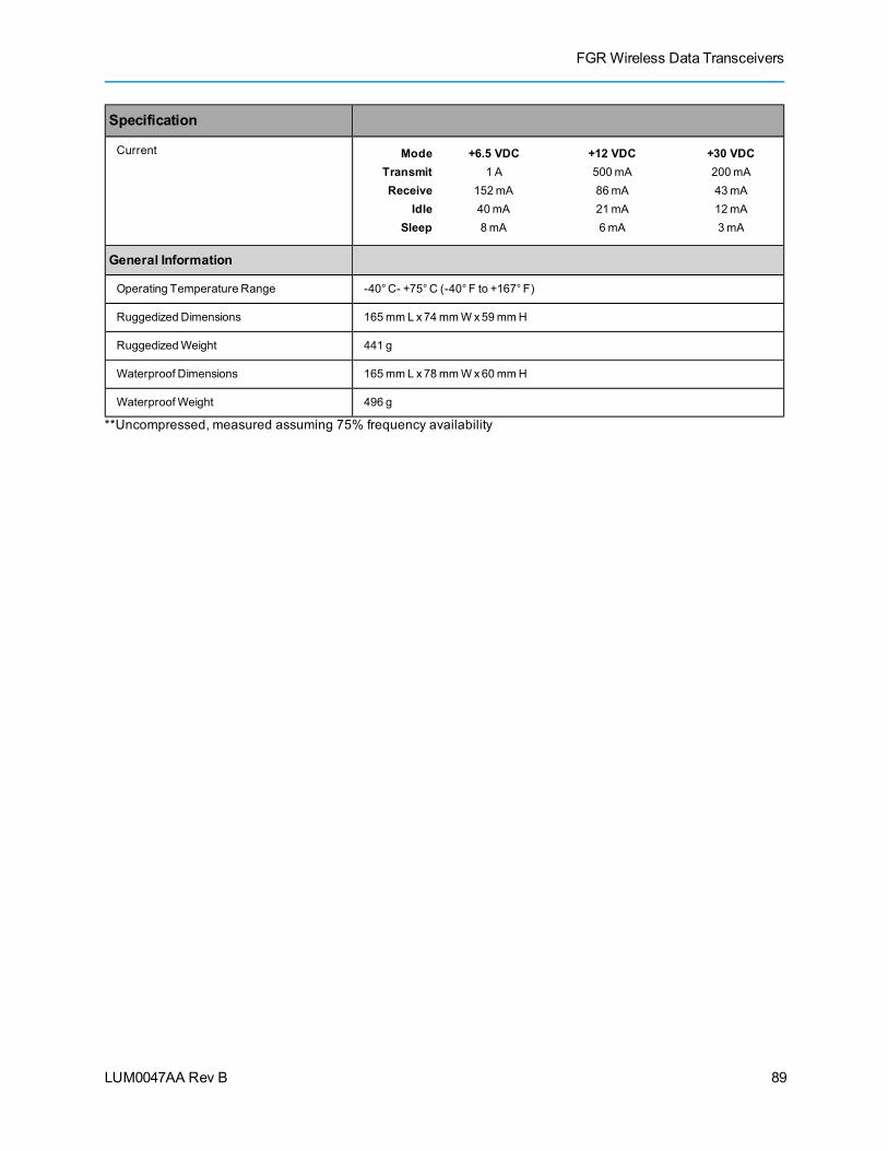
FGR Wireless Data Transceivers
LUM0047AA Rev B
Specification
Current Mode +6.5 VDC +12 VDC +30 VDCTransmit 1 A 500mA 200mAReceive 152mA 86mA 43mA
Idle 40mA 21mA 12mASleep 8mA 6mA 3mA
General Information
Operating Temperature Range -40° C- +75° C (-40° F to +167°F)
Ruggedized Dimensions 165mmL x74mmWx59mmH
RuggedizedWeight 441 g
Waterproof Dimensions 165mmL x78mmWx60mmH
WaterproofWeight 496 g
**Uncompressed, measured assuming 75% frequency availability
89

Chapter 8: Additional Transceiver Information
LUM0047AA Rev B
Factory Default SettingsFreeWave serial transceivers are shipped from the factory with the following default settings:
Operation Mode Default MultiPoint Parameters DefaultPoint-to-Point Slave 1 (0) NUMBEROF REPEATERS 1
Set Baud Rate Default (1) MASTER PACKET REPEAT 2
Baud Rate 19200 (2) MAXSLAVERETRY 9
(A) Data Parity 0 (3) RETRYODDS 9
(B) ModbusRTU 0 (4) DTR CONNECT 0
(C) RS232/485 0 (5) REPEATER FREQUENCY 0
(D) Setup Port 3 (6) NETWORK ID 255
(E) TurnOffDelay/OnDelay 0/0 (7) RESERVED -
(F) Flow Control 0 (8) MULTIMASTER SYNC 0
Radio Parameters Default (9) 1 PPSENABLEDELAY 255
(0) FREQKEY 5 (A) SLAVE/REPEATER 0
(0) HOPTABLEVERSION 0 (B) DIAGNOSTICS 0
(1) HOPTABLESIZE 112 (C) SUBNET ID “Disabled”
(2) HOPFREQOFFSET 0 Rx ID F
(3) FrequencyZone All 1s (Enabled) Tx ID F
(4) Government Rules 0 (D) RADIO ID Not Set
(1) MAXPACKET SIZE 8 (E) LocalAccess 0
(2) MIN PACKET SIZE 9 (G) Radio Name "blank"
(3) XMT RATE 1
(4) RF DATARATE 3(5) RF XMT POWER 10
(6) SLAVESECURITY 0
(7) RTSTOCTS 0
(8) RETRYTIMEOUT 255
(9) LOWPOWERMODE 0
(A) High Noise 0
(B) MCU Speed 0
(C) Remote LED 0
90
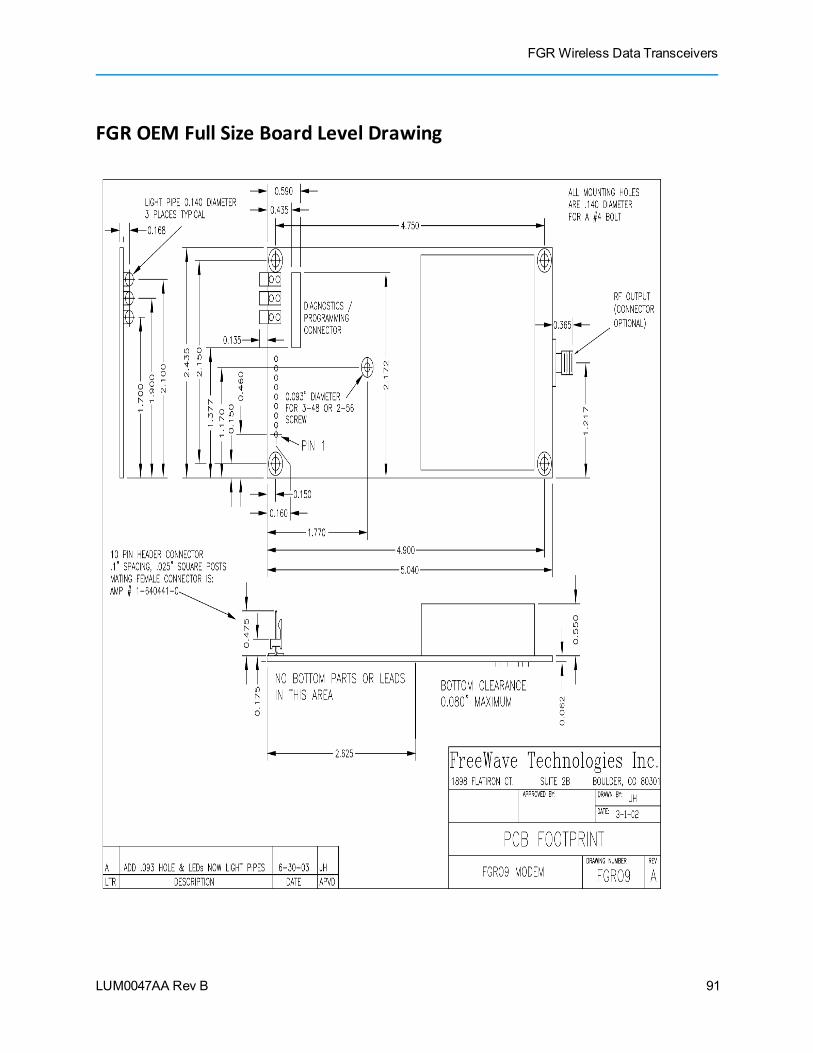
FGR Wireless Data Transceivers
LUM0047AA Rev B
FGR OEM Full Size Board Level Drawing
91

Chapter 8: Additional Transceiver Information
LUM0047AA Rev B
OEM Mini-Board Level Mechanical Drawing
92

LUM0047AA Rev B
Appendix A: Firmware Updates
As of this document's release, the following firmware has been released for themodel numbers to which thisdocument applies. The latest firmware versions are available on the FreeWaveWeb site atwww.freewave.com. You can also view the latest firmware available for most models in Tool Suite.
The sections below describe the updates and any known limitations in each firmware revision. Themostrecent version is listed first.
Version 2.69Release Date: September 2011
Additions/Updates: l Miscellaneous updatesl PPT RF sync fixesl Wire replacement bug fix
Known Limitations: None.
Version 2.68Release Date: March 2011
Additions/Updates: Wire replacement disconnect options and relink improvement.
Known Limitations: None.
93
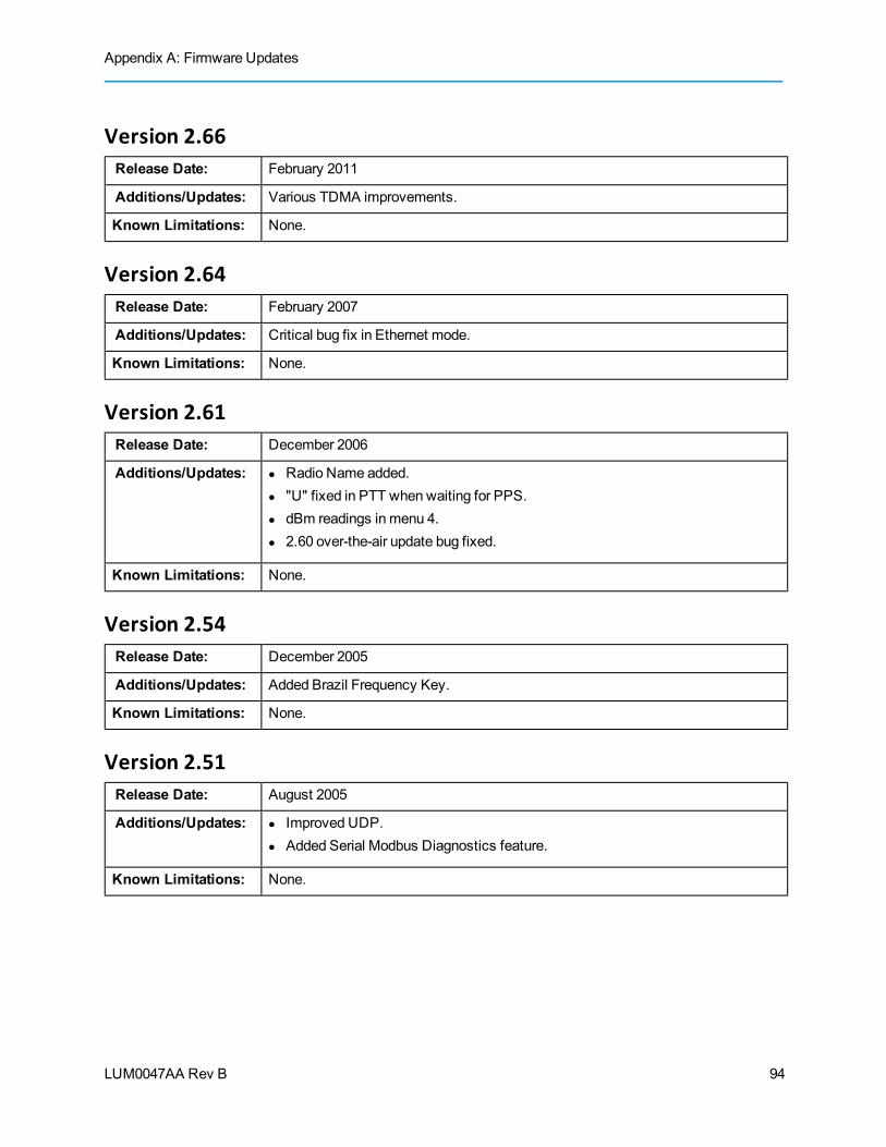
Appendix A: Firmware Updates
LUM0047AA Rev B
Version 2.66Release Date: February 2011
Additions/Updates: Various TDMA improvements.
Known Limitations: None.
Version 2.64Release Date: February 2007
Additions/Updates: Critical bug fix in Ethernet mode.
Known Limitations: None.
Version 2.61Release Date: December 2006
Additions/Updates: l Radio Name added.l "U" fixed in PTT when waiting for PPS.l dBm readings in menu 4.l 2.60 over-the-air update bug fixed.
Known Limitations: None.
Version 2.54Release Date: December 2005
Additions/Updates: Added Brazil Frequency Key.
Known Limitations: None.
Version 2.51Release Date: August 2005
Additions/Updates: l Improved UDP.l Added Serial Modbus Diagnostics feature.
Known Limitations: None.
94

FGR Wireless Data Transceivers
LUM0047AA Rev B
Version 2.47Release Date: May 2005
Additions/Updates: Added Vendor ID option.
Known Limitations: None.
Version 2.44Release Date: October 2004
Additions/Updates: Fixed a Repeater issue.
Known Limitations: None.
Version 2.40Release Date: August 2004
Additions/Updates: Several new features added. Details not provided.
Known Limitations: None.
Version 2.34Release Date: December 2003
Additions/Updates: Retry Odds issue fixed.
Known Limitations: None.
Version 2.33Release Date: November 2003
Additions/Updates: AddedModbus for Slave/Repeater.
Known Limitations: None.
95

LUM0047AA Rev B 96
Index
1
1 PPS Enable Delay, defined 48
A
Antenna Reflected Power, defined 69
B
Baud Ratedefined 22low rates 68
Baud Rate parametersBaud Rate 22Data Parity 22Flow Control 22Modbus RTU 23RS232/RS485 23Serial Interface 23Setup Port 24Turn Off Delay 25Turn OnDelay 25Use Break to Access Setup 25
C
Call Bookabout 62defined 26Point-to-MultiPoint networks 44-45Point-to-Point, 3 or 4 repeaters 64terminal interface setup 63Tool Suite setup 63
communication settings 21, 26configuration tools 7
D
data communication link examples 3Data Parity, defined 22default settings 10diagnostics, running 56
identifying transceivers 52parameter setting 49requirements 56
DTR Connect, defined 50
F
factory default settings 10, 90FCC notifications ivfirmware, upgrading serial transceivers 17Flow Control, defined 22FreeWave Technical Support, contating xiiFrequency Key, defined 27Frequency Zones, defined 28
G
golden settingsabout 26Frequency Key 27Max Packet Size 32Min Packet Size 32Network ID 26RF Data Rate 35
H
High Noise, defined 30Hop Table Size, defined 31Hop Table Version, defined 31HyperTerminal
and Tool Suite 8connecting 15described 7disconnecting 15
FGR Wireless Data Transceivers
LUM0047AA Rev B 97

Setupmenu, accessing 10troubleshooting 15
I
IC notifications ivinstallation
location, choosing 1mounting notes 6
L
LEDsdisplaying remotely 34Point-to-Point 62Point-toMultiPoint 43
legal notificationsFCC ivIC ivUL iii
Local Mode, defined 50locating transceivers 1low baud rates 68Low PowerMode, defined 54
M
Master-Slave Distance, defined 70Master Packet Repeat, defined
defined 50inMultiPoint networks with Repeaters 51
Max Packet Size, defined 32Max Slave Retry, defined 51MCU Speed, defined 34mechanical drawings 91-92Min Packet size, defined 32Modbus RTU, defined 23ModemMode, defined 19mounting 6Multi-Master Synch, defined 68
MultiPoint networksCall Book setup 44-45characteristics 40Network ID 44overlapping 43routing communication 45
MultiPoint parameters1 PPS Enable Delay 48Diagnostics 49DTR Connect 50Local Mode 50Master Packet Repeat 50Max Slave Retry 51Multi-Master Synch 68Radio ID 52Radio Name 52Repeater Frequency 52Repeaters 53Retry Odds 53Slave/Repeater 54
N
network diagnostics 56Network ID
defined 26MultiPoint networks 44setting 44
network type, setting 19Noise Level, defined 70notational conventions xiNumber of Disconnects, defined 70
O
OperationMode parametersModemMode 19SetupMode Timeout 8
OperationMode, defined 19
LUM0047AA Rev B 98
Index
P
packetsmaximum size 32minimum size 32
parallel Repeaters 65setting unique frequency 52
parameter reference1 PPS Enable Delay 48Baud Rate 22Data Parity 22Diagnostics 49DTR Connect 50factory default settings 90Flow Control 22Frequency Key 27Frequency Zones 28High Noise 30Hop Table Size (in 900MHz tranceivers) 31Hop Table Version 31Local Mode 50Low PowerMode 54Master Packet Repeat 50Max Packet Size 32Max Slave Retry 51MCU Speed 34Min Packet Size 32Modbus RTU 23Multi-Master Synch 68packet size 32Radio ID 52Radio Name 52Remote LED 34Repeater Frequency 52Repeaters 53Retry Odds 53Retry TimeOut 35RF Data Rate 35RS232/RS485 23RTS to CTS 36
Serial Interface 23SetupMode Timeout 8Setup Port 24Slave Security 37Slave/Repeater 54TDMA 68TimeDivisible Multiple Access (TDMA) 68Transmit Power 37Transmit Rate 38Turn Off Delay 25Turn OnDelay 25Use Break to Access Setup 25Xmit Power 37Xmit Rate 38
passwordsabout 67changing 67disabling 68setting 67
pinoutsFGR-115WC Waterproof Enclosure 82RF board-level 81RS232 (DB-9) 80RS422 and RS485 full duplex 80RS485 half duplex 80
Point-to-MultiPointabout 2Call Book setup 45getting started 40quick start 40
Point-to-MultiPoint networksCall Book setup 44characteristics 40LEDs 43Network ID 44operation LEDs 43, 62overlapping networks 43routing communication 45
Point-to-Pointabout 2
FGR Wireless Data Transceivers
LUM0047AA Rev B 99
Call Book with Repeaters 64getting started 59illustrated 3quick start 59
Point-to-Point networksCall Book 62
powerconserving 54Low PowerMode 54supplying 6
product serial numbers, locating 5programming tools 8
R
Radio ID, defined 52Radio Name, defined 52Radio Temperature, defined 70Rate%, defined 70Reflected Power, defined 69Remote LED, defined 34Repeater Frequency, defined 52Repeater, adding 66Repeaters, defined 53Repeaters, parallel 65Retry Odds, defined 53Retry TimeOut, defined 35RF Data Rate, defined 35routing communication 45RS232/RS485, defined 23RS232/RS485/RS422
operational information 79RTS to CTS, defined 36
S
Serial Interface, defined 23serial number, locating 5Setupmode
about 8accessing using Break command 25
HyperTerminal 10port assignment 24terminal interface 10Tool Suite 9troubleshooting 75
SetupMode Timeout, defined 8Setup Port, defined 24setup tools 7Signal Level, defined 71Slave Security, defined 37Slave/Repeater, defined 54specifications
FGR-115models 88FGRO9models 84FGRSR models 86
statisticsviewing 69
Status parametersAntenna Reflected Power 69Master-Slave Distance 70Noise Level 70Number of Disconnects 70Radio Temperature 70Rate% 70Signal Level 71Transmit Current 71viewing 69
Subnet IDassigning 46examples 46
T
TDMA, defined 68Technical Support, contacting xiitemperature reading 70terminal emulator
described 7TimeDivisible Multiple Access (TDMA), defined 68Tool Suite
and HyperTerminal 8
LUM0047AA Rev B 100
Index

connect to transceivers 9described 7
transceiver type, setting 19Transmission Characteristics parameters
Frequency Key 27Frequency Zones 28High Noise 30Hop Table Size 31Hop Table Size (in 900MHz transceivers) 31Low PowerMode 54Max Packet Size 32MCU Speed 34Min Packet Size 32packet size 32Remote LED 34Retry TimeOut 35RF Data Rate 35RTS to CTS 36Slave Security 37Transmit Power 37Transmit Rate 38Xmit Power 37Xmit Rate 38
Transmit Current, defined 71Transmit Power, defined 37Transmit Rate, defined 38troubleshooting
flow chart 74HyperTerminal 15network 75
Turn Off Delay, defined 25Turn OnDelay, defined 25
U
UL notifications iiiUse Break to Access Setup, defined 25
W
warranty ii
X
Xmit Power, defined 37Xmit Rate, defined 38
FGR Wireless Data Transceivers
LUM0047AA Rev B 101