
F/G 6/5 CENTRAL DENTAL EVACUATION SYSTEMS.(U) … · ad-ai16 653 school of aerospace medicine...
56
AD-AI16 653 SCHOOL OF AEROSPACE MEDICINE BROOKS AFR TX F/G 6/5 CENTRAL DENTAL EVACUATION SYSTEMS.(U) MAY 52 J M POWELL, J M YOUNG UNCLASSIFIED SAM-TR-82-12 NL END li
Transcript of F/G 6/5 CENTRAL DENTAL EVACUATION SYSTEMS.(U) … · ad-ai16 653 school of aerospace medicine...
AD-AI16 653 SCHOOL OF AEROSPACE MEDICINE BROOKS AFR TX F/G 6/5CENTRAL DENTAL EVACUATION SYSTEMS.(U)MAY 52 J M POWELL, J M YOUNG
UNCLASSIFIED SAM-TR-82-12 NL
ENDli
0) Review 3-82
AEROMEDICAL REVIEW
CENTRAL DENTAL EVACUATION SYSTEMS
Joseph M. Powell, Colonel, USAF, DCJohn M. Young, Colonel, USAF, DC
May 1982
DTICt ELECTE
~JUL 8 19Kj
a....Approved for public release; distribution 'unlimited.C:)
USAF SCHOOL OF AEROSPACE MEDICINEU- Aerospace Medical Division (AFSC)
Brooks Air Force Base, Texas 7823S
82 07 07008
NOTICES
This review was submitted by personnel of the Dental Investigation ServiceBranch, Clinical Sciences Division, USAF School of Aerospace Medicine, Aero-space Medical Division, AFSC, Brooks Air Force Base, Texas, under job orderDSB38900.
When U.S. Government drawings, specifications, or other data are used forany purpose other than a definitely related Government procurement operation,the Government thereby incurs no responsibility nor any obligation whatsoever;and the fact that the Government may have formulated, furnished, or in any waysupplied the said drawings, specifications, or other data is not to be regardedby implication or otherwise, as in any manner licensing the holder or any otherperson or corporation, or conveying any rights or permission to manufacture,use, or sell any patented invention that may in any way be related thereto.
This report has been reviewed by the Office of Public Affairs (PA) and isreleasable to the National Technical Information Service (NTIS). At NTIS, itwill be available to the general public, including foreign nations.
This technical report has been reviewed and is approved for publication.
) OPH M. POWELL, Colonel, USAF, DC J .YUG ooeUSAF, DCProject Scientist Supervi sor
ROY L. DEHARTColonel, USAF, MCCommander
UNCLASS IF IEDSECURITY CLASSIFICATION OF THIS PAGE 'When Date Entered)
REPORT DOCUMENTATION PAGE BEFORE COMPLETING FORM
I. REPORT NUMBER 2. GOVT ACCESSION NO. 3. RECIPIENT'S CATALOG NUMBER
Aeromedical Review 3-824. TITLE (and Subtitle) 5. TYPE OF REPORT & PERIOD COVERED
Final ReportCENTRAL DENTAL EVACUATION SYSTEMS August 1980 - July 1981
6. PERFORMING ORG. REPORT NUMBER
SAM-TR-82- 127. AUTHOR(*) 8. CONTRACT OR GRANT NUMBER(*)
Joseph M. Powell, Colonel, USAF, DCJohn M. Young, Colonel, USAF, DC
9. PERFORMING ORGANIZATION NAME AND ADDRESS 10. PROGRAM ELEMENT. PROJECT, TASK
USAF School of Aerospace Medicine (NGD) AREA A WORK UNIT NUMBERS
Aerospace Medical Division (AFSC) 87714FBrooks Air Force Base, Texas 78235 DSB38900
I I. CONTROLLING OFFICE NAME AND ADQRESS 12. REPORT DATEUSAF School of Aerospace Medicine (NGD) May 1982Aerospace Medical Division (AFSC) UMBER OF PAGES
Brooks Air Force Base, Texas 78235 5314 MONITORING AGENCY NAME & ADDRESS(If different from Controlling Office) 15. SECURITY CLASS. (of this report)
Unclassified
IS&. DECLASSIFICATION, DOWNGRADINGSCHEDULE
16. DISTRIBUTION STATEMENT (of this Report)
Approved for public release; distribution unlimited.
t7. DISTRIBUTION STATEMENT (of the abstract entered in Block 20, if diflerent from Report)
IS. SUPPLEMENTARY NOTES
19 KEY WORDS (Continue on reverse side it necessary and identify by block number)
Central evacuation systems, dentalOral evacuation systems, central, dentalSurgical suction, dental, centralDust-collection systems, central, dental
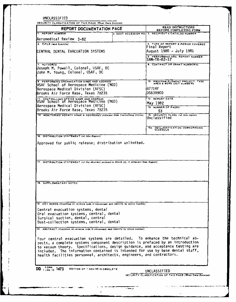
20. ABSTRACT (Continue on reverse side If necessary and Identify by block number)
Four central evacuation systems are detailed. To enhance the technical as-pects, a complete systems component description is prefaced by an introductionto vacuum theory. Specifications, design guidance, and acceptance testing areincluded. The information contained is intended for use by base dental staff,health facilities personnel, architects, engineers, and contractors.
DD 1jAN RM73 1473 EDITION OF I NOV 6S IS OBSOLETE UNCLASSIFIEDSECURITY CLASSIFICATION OF THIS PAGE (Rften Date Entered)
- . . i .... . . . . . . ..-.. ... . --... - . - -. .. . . . . . .

PREFACE
The information provided in this report is applicable both to exigent andspecified-loca on minor construction projects and to major military construc-tion projects. The purpose of this report is to
-a-. provide dental staff personnel with a more comprehensive knowledge ofthe design and function of central dental evacuation systems;
. -establish working details for the most efficient and cost-effectivelental evacuation systems consistent with present and projected military den-tal practice requirements;
' .-'provide clear, concise equipment configuration and performance re-quirements as guidance to health facilities offices so that they may closelysupervise planning for central dental evacuation systems; and
. provide procurement, installation, and performance criteria to con-tractors to assure delivery of equipment couisistent with quality design, lon-gevity, and clinical performance.,
" Four central dental evacuation systems (identified by AFM 88-50, Criteriafor Design and Construction of Air Force Health Facilities) are discussed.Part I of this report includes the theory of vacuum operation, the details ofthe systems, their component parts, and their function. Part I presentsspecifications, design guidance, acceptance testing, and utilities require-inents. Sufficient detail is provided to permit identification of well-designed systems and components as well as of those that do not meet U.S. AirForce requirements. A glossary of definitions and abbreviations is includedat the end of the report to enhance comprehension of the systems' descrip-tions, specifications, and design guidance.
-Accession For
NTIS GRA&IDTIC TABUnennounced ED
Justificatio
II
ByBy
- 1Distribution/ DT
Availability CodesIAvail and/or 2
D i t S p c a

CONTENTS
Page
PART I
INTRODUCTION.......................................................... 9
Vacuum Theory .................................................... 9Vacuum Generators................................................ 10
CENTRAL EVACUATION SYSTEMS ............................................ 13
High-Volume Oral Evacuation System (HVE) for Dental TreatmentRooms ......................................................... 13
Operational Parameters....................................... 13HVE System Components ....................................... 15
Clinical End Items...................................... 16Central Piping System................................... 16Central Separator ...................................... 16Drain Facility ......................................... 18Turboexhausters ........................................ 18Electrical Controls..................................... 20
Small-Facility HVE Systems................................... 20
High-Vacuum Oral Evacuation System (HIVAC) for Oral Surgery,Periodontics, and Endodontics Treatment Rooms..................... 20
Operational Parameters ...................................... 20HIVAC System Components...................................... 21
Clinical End Items...................................... 21Central Piping System.................................. 2Vacuum Pumps ........................................... 23Vacuum Reservoir ....................................... 23Electrical Controls..................................... 23
High-Volume Evacuation System for Base Dental Laboratories (HVEL) ... 24
Operational Parameters ...................................... 24HVEL System Components ...................................... 24
Inlet Fixtures ......................................... 24Central Piping Layout................................... 25Filter-Separator ... . . . . . . .. . . . . . . . . . .. . 25Vacuum Generator .................. ........... 27
Electrical Controls ... ... .. ..... .. .. ... ... 27
3iauw 1 l

Pa ge
Environmental-Janitorial Vacuum System (EJVS)....................... 27
Operational Parameters ...................................... 28EJVS System Components ...................................... 28
Wall Inlets ............................................ 28Central Piping System................................... 28Central Separator ....................................... 28Vacuum Generator ....................................... 28Accessories ............................................ 28Electrical Controls..................................... 29
Equipment Acceptance and Related Documentation...................... 29
PART 11
SPECIFICATIONS ....................................................... 30
High-Volume Oral Evacuation System (HVE) ........................... 30
Standard Products ........................................... 30Turboexhausters ............................................. 30Motor ...................................................... 31Isolation Pads.............................................. 31Pipe Isolators.............................................. 31Ingestion Valve ............................................. 31Directional Flow Valve ...................................... 31Antisurge Valve ............................................. 31Exhaust Silencer ............................................ 31Repair Items................................................ 32Controls.................................................... 32Central Wet Separators . ..................................... 32Piping ..................................................... 32Vacuum Relief Valve ......................................... 33Out-of-CONUS Installations .................. o................. 33
High-Vacuum Oral Evacuation System (HIVAC) ......................... 33
Standard Products................ ........................... 33System Configuration ........................................ 33High-Vacuum Pumps .......... ................... o.............. 34Motors ..................................................... 34Vacuum Reservoir (Tank)...................................... 34Controls ....... o............................................ 34Piping ..................................... o..... o.......... 34
High-Volume Evacuation System for Base Dental Laboratories (HVEL) ... 35
Standard Products ........................................... 35Turboexhausters .. o........................................... 35Motor ............................................ .o........ 36Isolation Pads.............................................. 36
4

Page
Pipe Isolators.............................................. 36Ingestion Gate.............................................. 36Exhaust Silencer ............................................ 36Repair Items................................................ 36Controls.................................................... 36Central Separator ........................................... 36Primary Separator ........................................... 37Piping ..................................................... 37Air Volume Relief Valve...................................... 37Vacuum Inlets............................................... 38Out-of-CONUS Installations................................... 38
Environmental-Janitorial Vacuum System (EJVS)....................... 38
Vacuum Source............................................... 38Central Dry Separator ....................................... 38Piping ..................................................... 38Vacuum Inlets............................................... 39Mobile Wet-Pickup Caddy...................................... 39Accessories................................................. 39
DESIGN GUIDANCE ...................................................... 39
Nigh-Volume Oral Evacuation System (HVE) ........................... 39
General Information ......................................... 39Composition of the System.................................... 40Design Criteria ............................................. 40
High-Vacuum Oral Evacuation System (HIVAC) ......................... 41
General Information ......................................... 41Composition of the System.................................... 41Design Criteria ............................................. 42
High-Volume Evacuation System for Base Dental Laboratories (HVEL) ... 42
General Information ......................................... 42Composition of the System.................................... 42Design Criteria ............................................. 43
Environmental-Janitorial Vacuum System (EJVS)....................... 44
General Information ......................................... 44Composition of the System.................................... 44Design Criteria............................................. 44
5

Pa ge
ACCEPTANCE TESTING.................................................... 45
Testing the High-Volume Oral Evacuation System (HVE) ................ 45
General..................................................... 45Pipe Leakage Tests .......................................... 45Air Volume and Vacuum Tests.................................. 45Recorded Test Data .......................................... 46
General Operating Test....................................... 46
Testing the High-Vacuum Oral Evacuation System (HIVAC) .............. 46
General..................................................... 46Pipe Leakage Tests .......................................... 46Vacuum Tests................................................ 46Recorded Test Data .......................................... 47General Operating Test ...................................... 47
Testing the High-Volume Evacuation System for Base DentalLaboratories (HVEL) ............................................ 47
General..................................................... 47Pipe Leakage Tests .......................................... 47Air Volume and Vacuum Tests.................................. 47Recorded Test Data .......................................... 48General Operating Test....................................... 48
Testing the Environmental-Janitorial Vacuum System (EJVS) ........... 48
General..................................................... 48Pipe Leakage Tests .......................................... 48Air Volume and Vacuum Tests.................................. 48
Operating and Maintenance Instructions Required for All Systems ...... 48
Bound Instructions .......................................... 48Diagrams and Operating Instructions ........................... 49Field Instructions .......................................... 49
UTILITY REQUIREMENTS.................................................. 49
H4igh-Volume Oral Evacuation System (HVE) ................ o.......... 49
Electrical Requirements...................................... 49
Turboexhausters ........................................ 49Turboexhausters' Remote Control Panel.....................5SOAutoflush.............................................. 50
Water Requirements...................................... .... 50
Liquid Separator ....................................... 50
Autoflush and Liquid Separator ........................... SO
6
Page
High-Vacuum Oral Evacuation System (HIVAC) .......................... 51
Electrical Requirements ........................................ 51Water Requirements ............................................. 51
Drain Requirements ............................................. 51Vent Requirements .............................................. 51
High-Volume Evacuation System for Base Dental Laboratories (HVEL)... 51
Electrical Requirement: Turboexhauster (Belt Drive) ........... 51Electrical Requirement: Turboexhauster Remote Control Panel... 52Electrical Requirement: Filter-Bag Shaker ..................... 52
Environmental-Janitorial Vacuum System (EJVS) ....................... 52
Electrical Requirements ........................................ 52Waste Requirements ............................................. 52Water Requirements ............................................. 52
GLOSSARY ................................................................. 53
7
- .-.- p - - - A-.

CENTRAL DENTAL EVACUATION SYSTEMS
PART I
INTRODUCT ION
Vacuum Theory
The performance of any vacuum generating system is based on two essentialfactors: (1) volume of airflow (CFM) and (2) vacuum pressure (inHg) main-tained in the system. In a functioning vacuum system, air is the transportingmedium for effluent and debris (rate of airflow determines volume trans-ported), while vacuum pressure provides the energy for transportation. Thesetwo essential factors operate in inverse proportion as demonstrated in Fig-ure 1:
E.-
Air Flow(CFM)
Figure 1. Vacuum system performance.
When vacuum pressure is at a peak, airflow is minimal, and vice versa.With few exceptions, a high level of either one of these factors does not pro-vide a practical vacuum system. A system with very high vacuum pressure butlittle or no airflow has energy to slowly move liquids and solids but lackssufficient volume to efficiently collect airborne debris. In addition, lowairflow cannot provide sufficient capture velocity to seize particulatesthrown from high-speed cutting operations. At the other extreme, a systemwith a high airflow but little vacuum pressure can move very lightweight air-suspended material but lacks the energy required to collect liquids and solidparticles with moderate mass.
r

Some vacuum systems are designed to operate in a performance range be-tween the extreme ends of the graph lines of Figure 1. The performancerequirements of this type of system are usually not critical and are generallythe result of a compromise between optimal performance and factors such ascost, weight, and portability. An example is the household vacuum cleaner.Hose attachments used on these units have varied intake sizes which affectboth airflow and vacuum pressure. Consequently these devices seldom operateat their potential optimum level of performance. Additional engineeringnecessary to fix the levels of airflow and vacuum pressure are not practicalin these portaule systems.
Conversely, the performance requirements of a dental evacuation systemare far more restrictive on design. These systems must be designed aroundspecific vacuum pressure and airflow levels determined to be most effective inscavenging liquids, solids, and aerosols. The system design must be such thatthe preset levels of these essential factors are maintained regardless of thenumber of using dental treatment rooms (DTR), from one to full clinic capac-ity. To maintain these levels, the vacuum generator requires specializedaccessories.
Vacuum Generators
In most commonly observed applications, a turbine is driven by the air,gas, or liquid medium passing through it and is coupled to some other deviceto perform work. A turbine can, when driven by an external mechanical force,be used as an exhaust or vacuum pump. In this type of application, the tur-bine is more appropriately termed a turboexhauster. This is perhaps the mostefficient and reliable means available for moving large volumes of air undervacuum pressure. In addition, the internal design of the turboexhauster givesit the unique ability to build and sustain predetermined levels of vacuumpressure. These two features qualify this exhauster as the ideal vacuum gen-erator for vacuum systems required to handle large volumes of air at low tomedium vacuum pressure.
A turboexhauster is basically a multistage centrifugal pump with rotors,or impellers, mounted one behind the other on a common shaft. These are il-lustrated by the diagonally striated parts in Figure 2. The path of airthrough the turboexhauster is indicated by the heavy arrow lines. Air entersthe front chamber (first stage) of the turboexhauster near the shaft center.From here air is picked up and given centrifugal (outward) acceleration by thefirst impeller. After leaving the axial tips of the impeller, the air under-goes a 180' change in direction and increases in acceleration. Fixed vaneslocated behind the impeller redirect the air back toward the shaft, to thebase of the next impeller. During this inward return, air velocity is reducedas its kinetic energy (energy of motion) is converted to pressure energy. Theincrease in pressure energy causes a corresponding positive pressure increaseat the pump outlet and a vacuum pressure increase at the inlet. The directionchange and pressure increase are repeated through each stage of the turboex-hauster. Consequently the vacuum pressure requirement for a specific systemdirectly influences the number of stages needed in the turboexhauster. Impel-ler dimensions also influence performance. Generally, increasing impellerwidth provides greater capacity, or airflow, and increasing impeller diameterimproves vacuum pressure.
10

The inherent characteristics of the turboexhauster make it ideal for thehigh airflow requirements of most dental evacuation systems. It is not, how-ever, suitable for use in a system where high pressure is essential, such as asurgical vacuum. The number of stages and the impeller diameter for such aturboexhauster would be prohibitive.
Figure 2 Turboexhauster (cross section).
{ 11
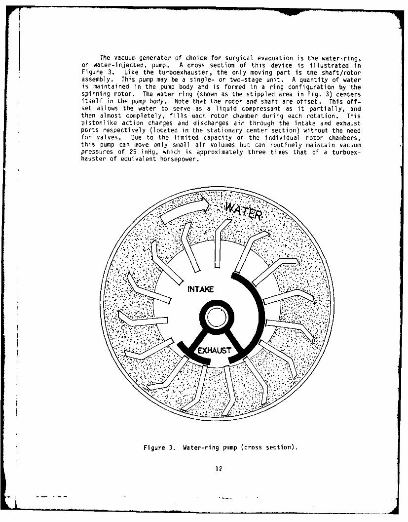
The vacuum generator of choice for surgical evacuation is the water-ring,or water-injected, pump. A cross section of this device is illustrated inFigure 3. Like the turboexhauster, the only moving part is the shaft/rotorassembly. This pump may be a single- or two-stage unit. A quantity of wateris maintained in the pump body and is formed in a ring configuration by thespinning rotor. The water ring (shown as the stippled area in Fig. 3) centersitself in the pump body. Note that the rotor and shaft are offset. This off-set allows the water to serve as a liquid compressant as it partially, andthen almost completely, fills each rotor chamber during each rotation. Thispistonlike action charges and discharges air through the intake and exhaustports respectively (located in the stationary center section) without the needfor valves. Due to the limited capacity of the individual rotor chambers,this pump can move only small air volumes but can routinely maintain vacuumpressures of 25 inHg, which is approximately three times that of a turboex-hauster of equivalent horsepower.
40. -V;,
Figure 3. Water-ring pump (cross section).
12

CENTRAL EVACUATION SYSTEMS
Four types of central evacuation systems are used in modern dental facil-ities. Two are for oral use: the high-volume evacuation system (HVE), usedthroughout the dental clinic in all patient-treatment areas; and the high-vac-uum evacuation system (HIVAC), used in specific disciplines of practice. Thethird central system is the high-volume evacuation system for dental labora-tories (HVEL), or the central dust-collection system as it is perhaps moregenerally described in lay terms. The fourth system is the environmental-janitorial vacuum system (EJVS), with inlets throughout the facility for envi-ronmental-protection housekeeping and cleanup procedures.
Due to their role as essential ancillary equipment for direct missionsupport, the two oral evacuation systems are dual in nature to provide a 100%capacity backup system in the event of vacuum-generator failure. The HVEL,being less highly stressed and of less priority in mission support, is pro-vided as a single vacuum-generator system. Each of the four systems is de-signed for a specific purpose and is therefore different in component makeupand perforinance. These systems must be discussed separately for a fullerunderstanding of their design and purpose.
High-Volume Oral Evacuation System (HVE) forDental Treatment Rooms
This central system, as its name implies, is designed to provide high-capacity air movement and does so at moderate vacuum pressure. It is specif-ically designed to collect and remove aerosols of water, saliva, and grindingor cutting debris from the mouth of the patient, especially during use ofthe high-speed handpiece. Inlets to this system are required throughout thedental facility for all disciplines of patient treatment where coolant andirrigation liquids are introduced into the operating field. These inlets areall connected to a central collection point and function as a wet-type system,with both air and liquid carried through the central piping. Vacuum is pro-vided by turboexhausters.
Operational Parameters
Essential factors of 15-CFM volume and 8-inHg vacuum pressure for thissystem were established through long-term clinical trial. The flow character-istics of blown air and exhausted air have a basic difference. The principleis illustrated in Figure 4. Air blown from an outlet of a given diameterretains its directional effect for some distance beyond the outlet or orificeface. The raw quantity of air being exhausted into a same-sized orifice isalmost completely nondirectional; therefore, its range of influence is greatlyreduced. In Figure 4, the air velocity at the face of each orifice is 3000FPM. Blowing air retains 10% of its initial velocity for a distance equal to30 times the orifice diameter. Exhausting air, on the other hand, retains 10%of its face velocity only I diameter from the orifice face. Actual values canbe applied to find an approximate spray velocity for a hypothetical handpiece,using the following airflow equation:
- - - ---

V =Q
A
where: V = Velocity (FPM)Q = Air volume delivered (CFM)A = Orifice area (ft
2)
BLOWING AIR i -500FPM
30 ORIFICE DIAMETERS
t-ORIFICE DIAMETERS ARE EQUALFAN I-FACE VELOCITY AT BOTH
ORIFICES = '00 FPM
7300 FPM
-EXHAUSTING AIR
I ORIFICE DIAMETER
Figure 4. Flow characteristics of blowing and exhausting air,
14

Assuming a volume delivery rate of 0.03 CFM through a handpiece sprayorifice 0.027 inch in diameter, a face velocity of approximately 7500 FPM iscalculated. At a distance of 30 orifice diameters (0.8 inch) from the sprayorifice face, the velocity should be approximately 750 FPM. To effectivelycapture this debris-containing aerosol at a nominal working distance of 0.5inch from the orifice of the evacuator tip, the evacuator-tip exhaust velocityshould at least equal, and preferably exceed, the spray velocity. By applyingthe specification values to the following exhaust-flow equation:
QV=
IOX2 + A
where: V = Air velocity (FPM) at X distance from the face of the evacuator-tip orifice
X = Distance (feet) from the evacuator-tip orifice faceQ = Air volume delivered (CFM)A = Evacuator-tip orifice area (ft2)
the following velocities are found for the distances shown:
0.25-inch distance from evacuator tip--3204 FPM0.375-inch distance from evacuator tip--1424 FPM0.5-inch distance from evacuator tip--800 FPM
From these values, the velocity of exhausting air can be seen to varyalmost inversely with the square of the distance from the face of the oral-evacuator-tip orifice. These figures also mathematically verify the principleshown in Figure 4.
A velocity of 800 FPM at a nominal working distance of 0.5 inch, withincreasing velocities at shorter working distances, has clinically been suf-ficient to control the debris-bearing coolant aerosol produced by the high-speed handpiece.
The vacuum pressure specified for the HVE system is 8-inHg draw. Thispressure and thp 15-CFM volume are the two P sential factors of a working HVEsystem. Clinical experience has dictated t-e 8-inHg value to supply suffici-ent vacuum pressure to scavenge pooled liquids and solid debris from the oper-ating site. This level of draw is also necessary to lift effluent through thepiping to the centralized separating device. In some installations, especial-ly retrofit situations, pipes for a central HVE system must be installed over-head in the attic space. In such cases, the vacuum pressure must be suffici-ent to raise the effluent to the central trunk lines. Since 8-inHg draw isthe equivalent of 109 inH20, the vacuum can lift effluent over 9 feet at eachDTR input. Properly trapped, this installation method is very successful buthas the disadvantage of higher cost for installation.
HVE System Components
The system begins with the clinical end items in the DTR for hands-on useby the treatment team. These include the suction tips, hand valve, hose, andsolids collector. The remainder of the system serves the central function for
15
- - - -.

all DTRs. These components include a custom-engineered plumbing network, acentral collector/separator, two turboexhausters, and an air exhaust directedto the atmosphere external to the facility. In new construction of dentalfacilities, each DTR will have several inlets to the central piping network.These will usually be stubbed into the wall-mounted utility centers located oneach DTR sidewall. Retrofit and remodeling projects may require only one in-let, depending upon casework layout and access to the DTR for pipe installa-tion. These cases often require stubbing into a floor-mounted utility center.
Clinical End Items--HVE tips, valves, hoses, and solids collectors, whileconsidered the clinical end of the system, are not generally provided by thecentral system manufacturer. To be physically compatible with the dentaldelivery system used, these items are produced by the delivery-system manufac-turer. They are usually found as part of the assistant's fixed-instrumenta-tion-package option and should be installed on an assistant's mobile cart whenDTR size and configuration permit. These clinical end items should be pro-cured from the central-system manufacturer only when such items will be free-standing and independent from the delivery unit or mobile-cart system.
The clinical end of the HVE system should be provided with two hoses andvalves. One hose and valve provides scavenging for nitrous oxide equipmentduring procedures requiring analgesic gas. The second hose and valve with tipserves the normal HVE function. Solids collectors from all unit and cart pro-ducers are available with dual hose connections.
Central Piping System--The central piping network and associated equip-ment are shown diagrammatically in Figure 5. The clinical end of the HVE sys-tem is connected to a specifically designed and sized central piping networkby individual 0.75-inch pipes known as risers, one for each solids collectorin the DTR. Risers begin in the DTR utility center and connect to either abranch or trunk line whose diameter is increased at intervals along its lengthto equate, in a cross-sectional area, the sum of the cross sections of therisers connected to it. This sizing is essential for continual movement ofcontained effluent. To further ensure effluent movement and to prevent linestagnation, the end of each branch or trunk line, slightly beyond the lastriser connection, must be equipped with a vacuum relief valve. This devicelets air bleed into the line to cause effluent movement when clinical inletsare turned off or are operating in minimal number.
Central Separator--All main trunk lines are routed to a central point atthe location of the turboexhausters and connect to a manifold at the separatortank inlet. More than one tank may be used, depending on the size of thefacility. Sizing criteria are found in DESIGN GUIDANCE in Part II of thisreport.
Separating tanks are cyclonic type and constructed of noncorrosive, inertmaterials, preferably glass-reinforced plastic (GRP) because of traces ofelemental mercury. Mercury will perforate metal tanks, especially theqalvanized variety. Inevitable corrosion will also shorten the life of metalseparator tanks. Effluent enters the tank tangentially near the top, under
vacuum pressure, and undergoes a swirling action. The liquid portion of thepffluent separates centrifugally and settles to the bottom of the tank. Ai'"
16
,,-

TURBOEX HAUSTER CL<
DIRECTIONAL VALVEVAE
L8i)
SEPARATOR YTAN K- *<DIRECTIONAL VALVE U
4 MANIFOLD0D
TRUNK LINEII
(2.5"1 (4
-REMOTE CONTROL PANEL 2
NOTE:-Z:SQUARE INCH1.
1. 2b" 4.9
VACUUM RELIEF VALVE
Figure 5. HVE functional diagram.
17

is drawn from the top of the tank and enters the turboexhauster. The separa-tor tank must have several protective devices to prevent accidental entry ofliquid into the turboexhausters. First, the tank is equipped with an elec-trically operated liquid-level sensor with detectors at the full and emptypositions. In a single-tank installation, when the full condition is detec-ted, the turboexhauster automatically shuts down for a few minutes, until thetank drains, and then restarts. In a multitank installation, the detectorcloses a solenoid valve at the top of the tank until the tank automaticallydrains and returns to service; meanwhile, the system continues to operateusing the other tank. Single-tank installations are sized so that HVE serviceis not interrupted for draining during a normal duty day.
A second, or backup, safety device is required--a float cutoff at the topof the tank which stops effluent entry into a full tank until it is emptied.If the shutoff float fails, the turboexhauster must be manually switched offfor the tank to drain.
All tanks are equipped with a gate or swing-type check valve at the bot-tom drain. While vacuum pressure is in the tank (system operating), the checkvalve remains closed to maintain vacuum. When vacuum ceases, as when theturboexhauster is shut down or the air-outlet solenoid closes, the drain checkvalve falls open and the tank drains.
Each tank is equipped with an automatic clock-controlled internal wash-down system (autoflush). The controller clock is set to activate an adjust-able-time washdown cycle during off-duty hours to flush and remove sludge toprevent stagnation and buildup of precipitates inside the tank. Criteria fortank capacity needed for various facility sizes are found in DESIGN GUIDANCEin Part II of this report.
Drain Facility--Although not a true component of the HVE system, drainageto sewer is an important aspect of system installation and must be thoroughlyconsidered in the planning stage. In planning for new facility construction,a 12xl2x6-inch floor sink with a 3-inch drain must be placed at or very nearthe location of the separator tanks. This size floor sink can handle thegravity drain discharge. In any construction or remodeling where a floor sinkcannot be used and effluent must be moved overhead, a high-pressure pump mustbe included as part of the system. A sump pump should not be substituted forthe high-pressure in-line pump. Sump pumps are not reliable enough nor arethey capable of sufficient performance to handle tank drainage. The in-linehigh-pressure pump is controlled by the liquid-level sensors in the separatingtank(s) and can empty a tank without interruption of HVL service. When over-head pumping of drainage is required, include the high-pressure pump as partof the system equipment.
Turboexhausters--Fxcept for very small clinics, each dental facility willbe equipped with at least two turboexhausters. Each will be sized to handle100% of the calculated HVE requirement for the whole clinic. The very heavydependence of modern dental techniques and associated equipment on 3 reliableHVE system dictates a 100% backup system in case of turboexhauster breakdown.The two turboexhausters will be used alternately; for example, one used on oddand the other on even days of the month. Alternated use of paired turboexhausters has been reported to provide tip to four times the service life of asingle unit used daily.
- -ilE l-- ag i - -.. .. . l-l . .. . . . "- . .-. . .. . I1 . .
Large turbines required to supply 100% use rate to large facilities arenot consistently heavy consumers of energy. When operating with less thanthe full clinical load, these units do very little work to move air; there-fore, their energy consumption is small. Demand is placed on the turboex-hausters only when a large number of users are on line. During these briefperiods the turboexhauster drive motor is operating at or near its designedcurrent draw, which for systems of this type is a lesser draw than for multi-ples of small turboexhausters operating simultaneously to produce the samework.
The turboexhausters are installed from the separator tank(s) and parallelto each other. Each exhauster must have in its input line a swing-type checkvalve to prevent backflow during maintenance or operation of the oppositeunit. Each unit nust also have in its input line an ingestion gate to reg-ulate the maximum air input to the turboexhauster. This gate is an adjustablebutterfly-type valve which provides a finite setting for the 15 CFM at eachDTR input and keeps the exhauster from ingesting more air than it was desiynedfor (which would burn out its drive motor due to overload). Located at thefirst stage of each turboexhauster is an antisurge valve. This is an adjust-able mechanical device that bleeds air into the exhauster to maintain a con-stant level of vacuum pressure in the system regardless of how many using DTRsare on-line. Continual monitoring and compensation for surging by this valvereduces temperature buildup in the turboexhauster, thus enhancing its servicelife and efficiency.
To provide the 8-inHg draw required by the specification, the turboex-hauster must incorporate at least six stages. It must also be of the out-board-bearing design, which means that the exhauster and its drive motor musthave independent bases: the turboexhauster must not be supported in any wayby the motor. This design provides far greater shaft and bearing life andsimplifies realignment of motor and exhauster shaft when bearings must bereplaced. Turboexhausters require special noise and vibration control. Theexhauster and its drive motor are rigidly mounted on a frame of box-sectionsteel rails. Rubber isolator pads between this frame and the structure floorabsorb vibration and prevent its magnification. The inlet pipe and exhauststack are mounted to the exhauster through resilient piping isolators to pre-vent vibration and noise transmission into the central system. Each turboex-hauster requires a muffler or silencer mounted in-line in the exhaust stackfor noise control. These silencers should be the straight-through absorptiontype to prevent backpressure on the exhauster. Stacks for the exhaustersshould exit straight through the roof of the housing structure, preferablywith no bends or turns, again to minimize backpressure.
The general rule in sizing vacuum generators for the HVE system is tomultiply the total number of DTRs in the facility by 15 CFM and then compen-sate for line losses caused by inherent restrictions in the plumbing and asso-ciated equipment. For clinics with up to 20 DTRs, a 10% increase is used.For clinics with more than 20 but less than 40 DTRs, a 15% increase should beused. For larger facilities, a 20% increase may be required to compensate forline losses in very complex central piping systems with many directional turnsin the pipe runs. The corrected total CFM value is applied to the sizingchart in DESIGN GUIDANCE in Part I of this review. From this chart the prop-er horsepower/CFM combination is selected.
19
Electrical Controls--The turboexhausters are controlled via a remote con-trol panel located in a convenient, easily accessible area of the facility.The most popular installation site for this panel has been near the recordsand reception area, where staff personnel are always present during normalduty hours. This location is also convenient for the person in charge ofquarters and the duty officer handling emergencies during other than normalduty hours. The panel contains a system vacuum gauge and on-off indicatorlights and power switches for each turboexhauster.
The remote control system is powered by a low-voltage transformer (24VAC) and requires only small-gauge (#14) wiring between the panel and theequipment site. The equipment manufacturer must provide an electrical controlpanel with magnetic starters to provide high-voltage switching of the turboex-hauster motor by the low-voltage signals from the remote control panel. Theelectrical control panel is located at the same place as the turboexhausters.
Small-Facility HVE Systems
For very small clinics (2-4 DTRs), a pair of high-quality water-ring (orwater-injected) pumps may be used to provide HVE service. When the pumps areselected, the capability of each pump to provide 15 CFM, with 8-inHg draw(vacuum pressure), at each DTR must be ensured. The plumbing and remote-con-trol criteria that apply to the turboexhauster system also apply to the water-ring pump substitute system. Water-ring pump systems are available with thecentral separator incorporated in the pump-cabinet enclosure. Since the sepa-rator does not have an automatic drain feature, clinic personnel must organizea schedule for manual emptying and changing.
High-Vacuum Oral Evacuation System (HIVAC) for Oral Surgery,Periodontics, and Endodontics Treatment Rooms
The HIVAC system is designed to build and sustain high vacuum pressuresat very low airflow. Specifically, this system provides for safe removal ofviscous fluids, suture material, and hard- and soft-tissue debris from surgi-cal wound sites, without damage to normal tissue or dislodgement of freshlyformed blood clots. Inlets to this central system are located in oral sur-gery, periodontics, and endodontics 0TRs: all disciplines that create opensurgical wounds in their treatment procedures. All inlets are connected to acentral piping network that operates as a dry-type system, with individualseparators and related hardware located in each using DTR. The vacuum genera-tors for this system are water-injected (or water-ring) pumps.
Operational Parameters
The 1-2 CFM and 15-20-inHg vacuum power are classic values establishedthrough many years of operating room experience. The very high vacuum pres-sure is required to scavenge viscous fluids (such as blood and saliva) andgrasp tissue debris for removal from the surgical site. The very low airflowis necessary to prevent grab and injury of delicate soft tissues and acciden-tal removal of clots that are forming. This combination of air supply andvacuum pressure provides a much slower acting system--ideal for the delicatefunction it serves--than the fast-acting HVE system previously described.
20 r

HIVAC System Components
For this system only one inlet is provided for each using DTR. In newconstruction, the inlet is equipped with a faceplate and quick-disconnectvalve and is located with the medical gas outlets on the entry wall of theDTR. Retrofit and remodeling projects may call for a different location de-pending upon installation access, casework, and equipment layout. All inletsare connected to a specially sized and engineered central piping network lead-ing to a vacuum reservoir and pumps. The type and location of the clinicalend items (used by the treatment team in patient care) within the DTR are verydifferent from those of the HVE system previously described.
Clinical End Items--The clinical end items for the HIVAC system are free-standing; that is, they are not normally attached to other pieces of dentalequipment (as are components of the HVE system). As a result, these items canbe supplied by the manufacturer of the HIVAC central system or from othersources. All components of the clinical end items should be procured from thesame source to assure compatibility within the assembly. All parts, incudingthe quick-disconnect fittings for the regulator and wall inlet valve, must behospital grade to assure good performance and service life. The clinical enditems include the surgical tips; hose; a shatter- res istant suction bottleassembly with wall bracket, cap, and float; an overflow safety trap; and asuction regulator and gauge assembly. The suction bottle hangs from the wallby its own bracket, and to the bottle is attached the suction-tip hose and ahose connection to the safety trap. The safety trap is attached directly tothe bottom of the regulator, and the regulator is attached by a mating quick-disconnect fitting to the wall-mounted vacuum service inlet. When not in use,the clinical end items are disconnected as a unit and stored.
The regulator must have an exterior knob to allow hand adjustment of vac-uum from 0 to full capacity. The regulator also must contain an easily read-able gauge for monitoring the vacuum (its agreement with the set adjustment).
In the vacuum scavenging of blood, much foaming can occur in the suctionbottle. If the suction bottle float is not activated by foam, the contaminantspills over into the central piping. To prevent this, an overflow safety trapmust be included in the system.
Central Piping System--The central plumbing network and associated equip-ment are shown diagrammatically in Figure 6. The vacuum inlet valve (stationinlet) located on the wall of using OTRs has a quick-disconnect fitting thatreceives and holds a mating fitting on the rear of the regulator. When theclinical end items are removed from their wall mounting and the regulator isunplugged from the inlet valve, the valve must automatically close to seal thecentral system against leakage. Unlike the HVE, the HIVAC is a sealed sys-tem. That is, air enters the central piping only through the regulators inthe using DTR during patient treatment procedures. The system i s a dry oneand therefore needs no bleed air to carry pipeborne effluent. The wallI-mounted inlet valves are connected to the central network by 0.5-inch riserpipes. All branch and trunk lines to which the risers are connected are a
21
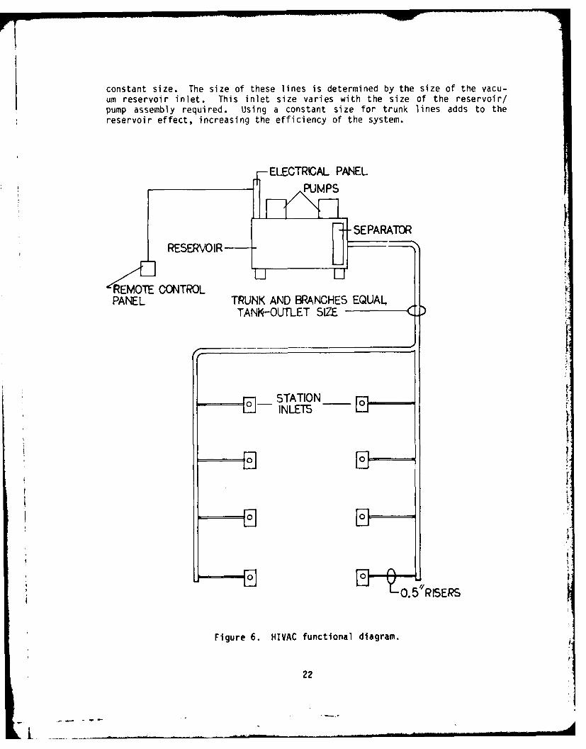
constant size. The size of these lines is determined by the size of the vacu-um reservoir inlet. This inlet size varies with the size of the reservoir/pump assembly required. Using a constant size for trunk lines adds to thereservoir effect, increasing the efficiency of the system.
ELECTRICAL PANEL
RESERO IR - SEPARATOR
REMOTE CONTROLPANEL TRUNK AND BRANCHES EQUALTANK -OUTLET SIZE
STATION [
INLETS
0. 5"RISERS
Figure 6. HIVAC functional diagram.
22

Vacuum Pumps--All HIVAC systems will have two water-ring (or water-injec-ted) pumps, ehter capable of the full design load of the system. The elec-trical panel to control the pumps must have the capability to automaticallyalternate the pumps for each start. The pumps- are connected in parallel, andeach has a swing-type soft-seat check valve in its input to prevent backflowfrom the unit not in operation. Dual vacuum switches, mounted on the vacuumreservoir tank, monitor the vacuum. One pump pulls the system down to thespecified vacuum pressure and then shuts down until using DIRs bleed offenough vacuum to cause the other pump to operate, thus maintaining the presetvacuum pressure.
Like the sizing criteria for the HVE system, the HIVAC system size isbased on total volume capacity required. The number of using DTRs (oral sur-gery, periodontics, and endodontics) is multiplied by 2 CFM to obtain thetotal load requirement, and the product is corrected by adding 10% to compen-sate for line loss (internal friction of the plumbing). The corrected volumeis then multiplied by a use factor of 0.8, and the result is used to selectthe proper pump capacity. Pump size is selected so that each pump is capableof the above calculated load. These systems are available ready to tie in topiping and electrical supplies. The sizing chart for these units is given inDESIGN GUIDANCE in Part II of this report.
Pumps continually ingest water to maintain the vacuum-generating capabil-ity. Immediately after leaving the pump, the water is discharged as an air/water mixture into a separator. The separated air and water are exhausted toa piping vent and sanitary sewer drain respectively. Pumps must be hospitalgrade, of heavy-duty cast-iron construction with corrosion-resistant rotors toenhance longevity. Pumps are mounted directly on the vacuum receiver orreservoir.
Vacuum Reservoir--The vacuum reservoir (or tank or receiver, as it isoften called) must be constructed of corrosion-resistant material. Althoughthe system is the dry type, the high-humidity air it ingests will allow somecondensation in the reservoir. For this reason, the reservoir must beequipped with a manual valve at its lowest point for occasional draining.
The only purpose of the reservoir is to serve as a vacuum ballast, muchas does the tank in a compressed-air system. The reservoir allows the build-up and containment of a reserve of vacuum to prevent rapid cycling of thepumps and surging of the vacuum service. It must be constructed to withstandthe specified vacuum plus the safety margin required for such devices and mustinclude necessary control devices (vacuum sensors and switches for automaticpump operation), threaded inlets and outlets for associated pipes, drilledfeet for site anchoring, and all other parts and devices included in the com-plete system.
Electrical Controls -- Mai n-power on-off switching for the HIVAC pumps isprovided by a remote control panel like that for the HVE system. Unlike theHVE system, the HIVAC system does not run continuously. These pumps are in-termittently switched on and off by the pressure-sensitive devices on the vac-uum reservoir that respond to the clinical demand. The devices act throughthe magnetic starters in the electrical control panel supplied with the equip-ment package. The panel for the HIVAC pumps must also provide an alternating
23

I -feature. That is, each time the vacuum-pressure sensors call for a pump tostart, the control panel must automatically alternate the pump in service.Both the remote-control panel and the tank-mounted electrical control panelshould be supplied as part of the system package to assure compatibility.
High-Volume Evacuation System forBase Dental Laboratories (HVEL)
This central system is specifically designed to collect, separate, andfilter dry dust and cutting, grinding, and polishing particulates from thedental laboratory work space. Inlets to this system are located at the tech-nicians' sitdown benches and at pieces of stationary abrasive, grinding, andfinishing equipment. All inlets are connected to a centrally plumbed networkrouted to a central separator and filtering device. Vacuum for the system isproduced by a high-speed belt-driven turboexhauster.
Operational Parameters
Long experience in particulate scavenging in industrial processes pro-vides an excellent background for determination of essential factors for theHVEL system. These factors have been established at airflow volumes of 60 and150 CFM at 3-inHg draw. The 60 CFM applies to the inlets located at the tech-nicians' sitdown task areas, and the 150 CFM is used for scavenging the hoodsof stationary equipment such as air abrasive units and polishing/finishinglathes. These very high airflow volumes are required so that the exhaustingair will have the velocity needed to collect and remove airborne particu-lates. Air velocities at these airflow volumes do generate noise; however,measured on a time-weighted basis, they pose no danger of hearing impairment.The system requires only a relatively low level of vacuum pressure to move dryaspired debris through the central piping to the separator/filter.
HVEL System Components
The HVEL system begins with the individual inlets in the front face ofthe service ledge located at the rear of all dental laboratory casework (cabi-nets and benches). These inlets are connected to a central piping networkspecifically sized for each installation. This network connects to a centralfilter/separator unit evacuated by a belt-driven high-speed turboexhauster.
Inlet Fixtures--The HVEL system uses two inlet sizes. A 1.5-inch inletis used to exhaust the hoods and interiors of fixed equipment such as sand/shell blast cabinets, microabrasive cabinets, polishing and finishing lathes,and high-speed grinders. These inlets are designated to provide 150 CFM ofexhausting air. The technicians' sitdown task benches are equipped with1.25-inch inlets designated to provide 60 CFM of exhausting air to handle par-ticulate scavenging from slower speed hand grinding and cutting. These inletsprovide vacuum for the small fishmouth-type hoods located on the bench top.All inlet fixtures include a top-hinged, vertically swinging cover lined withneoprene or rubber. When not in use, the cover swings down to seal the inletorifice against leakage and unnecessary high-velocity-air noise.
24

The cross-sectional area of the inlets to the central system governs theCFM of air passing through that particular inlet size. The capacity of theturboexhauster limits the total usable capacity of the system.
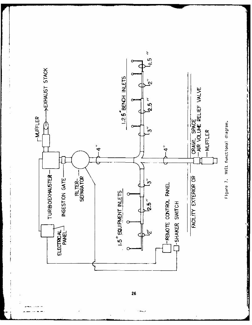
Central Piping Layout--Central piping and associated equipment are showndiagrammatically in Figure 7. Like that for the HVE, branch lines of the HVELsystem are progressively increased in cross-sectional areas by standard pipesize to equate the sum of the cross-sectional areas of the inlets attached.For calculation purposes, the 1.25-inch inlets have a cross section of 1.23square inches. A correction factor of 1.1 to compensate for line frictionloss is applied, bringing the design cross section to 1.35 which is used tocalculate the progressive cross section. The 1.5-inch inlets measure 1.77square inches in cross section and are compensated to 1.95 square inches fordesign use. The sum of the cross-sectional areas of all branch lines is usedto select the final and largest pipe, the trunk line, that connects to thefilter-separator. To balance the system, the trunk line must be extended pastthe intersections of all branches to a point in a crawl space or to the exte-rior of the facility. At the end of this trunk run, an air volume reliefvalve is installed. This valve is sensitive to vacuum pressure (inHg draw)which operates a large-capacity air gate within the body of the valve. Whenfew using inlets are on line, the air gate senses a tendency toward increasedvacuum pressure and bleeds air into the system to prevent excessive volume in-take at the operating inlets. By its ability to respond to fluctuating ten-dencies in vacuum pressure as inlets come on and go off line, the air volumecontrol valve helps to maintain designed airflow through the inlets, reduceshigh-velocity-air noise, and in the large trunk line provides air velocitynecessary to move ingested particulates downstream to the filter-separatorunit. The remote location of the air volume valve and its attached muffler isrequired because of the potential for high-velocity-air noise.
Filter-Separator--The main trunk line of the HVEL system is plumbeddirectly to the central filter-separator located close to the turboexhaustersupplying its vacuum. The filter-separator is a cyclonic type that swirls theincoming debris-laden air to cause separation. Debris is dropped into awheeled, removable container at the bottom of the unit. The air is takenthrough a system of filter bags before leaving the top of the unit on its wayto the turboexhauster. The filter-bag system is equipped with an electrically:operated shaker that drops accumulated dust from the exterior of the bags intothe debris container. The control for the shaker should be located with theturboexhauster remote control panel at a convenient site within the labora-tory. A daily shakedown of the bag system maintains the efficiency of theseparator. The debris container is attached to the bottom of the separator bya cam lock that seals against vacuum loss and facilitates removal for empty-ing.
Criteria for selecting filter-separator size are in DESIGN GUIDANCE inPart II of this report. Nominal physical dimensions for these units rangefrom 72 to 120 inches in height and from 24 to 28 inches in diameter. Weightrange is 250-720 pounds. Filter-bag area range is 40-300 square feet.
In laboratories equipped with sand-blasting units without a built-in fil-ter system, an in-line primary filter must be installed between the sand-blaster exhaust outlet and the HVEL input. Primary filters, when required,are considered part of the HVEL system and should be supplied with it.
25
-A
liC)l
I-iVI) z
WL LOw LL'o w-i
w ~w C-1 0E
U- <UlU
-- J
Hr c
0 I -0
z mI-<2
mw
ww
W- M26
Vacuum Generator--The vacuum generator for the HVEL system is a singlebelt-driven turboexhauster. Because this system has a low level of opera-tional stress imposed on it and is a nonclinical item (with reduced signifi-
cance in normal use as well as in a contingency situation), a second or backupvacuum generator is not justified.
The turboexhauster has fewer stages than its counterpart in the HVE sys-tem because of the comparatively low vacuum pressure specified (3 inHg) forthe HVEL. The air volume requirement, however, is much higher than for any ofthe other dental evacuation systems. To provide this increased airflow, abelt-driven system allows more rpm by the turboexhauster. An added advantageis that the belt drive provides a convenient and economical method for adjust-ing the rpm (therefore, the airflow) to fine tune the system.
The air volume relief valve described under Central Piping Layout servesas the antisurge valve for the HVEL. Since the system does not ingest liq-uids, vacuum relief valves are not required at the ends of branch lines.
As with the HVE, the HVEL system is equipped with an ingestion gatebefore the first turboexhauster stage. This gate prevents ingestion of airvolume above that for which the system was designed. Larger airflow producesincreased load on the turboexhauster drive motor, causing it to overdraw elec-trical current beyond its rating and thus burn out.
The HVEL unit requires pipe and base-frame vibration isolators and air-outlet mufflers as described for the HVE turboexhausters.
Electrical Controls--The HVEL turboexhauster is switched on and off via aremote control panel installed in a convenient location within the labora-tory. As with the HVE, this low-voltage remote panel switches the turboex-hauster's magnetic starter, located in the electric control panel at the ex-hauster. The remote panel contains stop and start buttons, a visual on-offindicator light, and a vacuum pressure gauge (inH2 0). The comparatively lowvacuum pressure of the HVEL system is more easily displayed by the inches-of-water gauge (1 inHg = 13.6 inH20) than with an inches-of-mercury gauge as usedin higher vacuum pressure systems.
A conventional 115-VAC switch is required, separate from but near theremote panel, to control the filter-bag shaker motor installed on the cen-tral filter-separator.
Environmental-Janitorial Vacuum System (EJVS)
The EJVS is an add-on system designed to provide a safe and efficientcentral vacuum for recovering toxic or hazardous materials such as elementalmercury. It is also a safe and efficient adjunct for general housekeeping inareas where mercury might be a background contaminant, as well as in all otherareas of the facility. Utilizing vacuum produced by the HVE system turboex-hausters, the EJVS is economical to install and operate and replaces a re-quirement for other commercial and vaporproof cleaning equipment. In facil-ities where housekeeping is contracted, costs should be less than if the con-tractor were required to provide vacuum cleaning equipment, especially the
27

vaporproof type needed for cleaning areas where mercury is used. The EJVS isequipped with wheeled, portable wet-separator tanks to provide a wet-dry vac-uum cleaning capability and uses commercially available cleaning hoses andimplements.
Operational Parameters
Using the turboexhausters of the HVE, the EJVS system operates at 8-inHgvacuum pressure. The other essential factor, volume of airflow, is governedby the number of hoses operating at one time. The usual flow is between 100and 150 CFM. Both of these factors exceed those of a commercial portable vac-uum cleaner.
EJVS System Components
Except for its vacuum source, the EJVS is similar to other central vacuumsystems used in residential and commercial structures. Strategically placedinlets lead to a properly sized piping network, terminating at a filter-sepa-rator. The unique feature of the EJVS is its use of the HVE turboexhausterfor vacuum to drive the system.
Wall Inlets--Inlets to the EJVS are commercially available wall valvesconstructed of stainless steel. Nominal dimensions of the frame and door areapproximately 4.6x4.6 inches. The assembly has beveled edges for safety andprotrudes approximately 0.5 inch from the wall. The door is vertically swungand lined with neoprene to effectively seal the 1.5-inch orifice when not inuse. Wall inlets are the nonautomatic type (no vacuum generator switch) sincethe turboexhausters powering the system are switched from a remote panel.
Central Piping System--The individual wall inlets are generally connectedby 1.5-inch pipe to a 2-inch branch line. The 2-inch branch line can handletwo users without appreciable drop in air volume through the hoses and clean-ing implements and is sufficient for a suite or module of DTRs. Branches fromsuites and modules should connect to a 3-inch trunk line leading and connec-ting to the filter-separator.
Central Separator--Main trunk line(s) connect to a cyclonic-type dryfilter-separator identical to that used for the HVEL system. A remote switchto control the filter-bag shakedown motor should be located near the remotepanel controlling the HVE turboexhauster. The filter-separator is located ator very near the turboexhauster, not in an area of frequent traffic. There-fore, to ensure against decreased efficiency and ultimate damage from neglect,a definite schedule must be set up for emptying its collection container.
Vacuum Generator--Vacuum for the EJVS is provided by either of the HVEsystem turboexhausters. Since these vacuum generators exhaust to the atmo-sphere exterior to the facility, the EJVS is ideal for handling toxic materialspills such as elemental mercury. Any vapor generated in pickup is safelydisseminated outside the facility.
Accessories--Each facility should be provided with at least one mobilewet-pickup caddy. This portable device is a two-wheeled 12-gallon tank withhandle. It is equipped with a short jumper hose for connection to a wall in-let and is used with 30-foot-long 1.5-inch vacuum hoses to pick up liquid
28
spil Is, washes, or other wet duty. The caddy tank has a built-in float toprevent overflow and an expansion-plug drain for emptying. The caddy shouldhave implement tips that include a master shoeholder with shoes for smoothfloors and carpets, a squeegie shoe for wet pickup, a crevice tool, a dustingbrush, an upholstery tool, and a 5-foot-long aluminum S wand. The number ofhoses and implements is determined by facility size. DESIGN GUIDANCE in Part11 of this report offers further information on quantity.
Electrical Controls--The only electrical control required for the EJVS isa switch for the filter-separator filter-bag shaker motor. This switch can beinstalled at any convenient location, preferably near the remote-control panelfor the HVE system turboexhausters. This switch is usually a 115-VAC typesimilar to that used for room-ceiling light fixture control and may be wireddirectly to the shaker motor without relays or magnetic starters.
Equipment Acceptance and Related Documentation
After any of the four systems discussed have been installed, performancetests must be made. These test results determine whether or not the systemsare acceptable to the responsible authority. Equipment or assembled systemsthat do not conform to the design guidance given in Part 11 of this reportshould not be accepted for use. The contractor is responsible for making anycorrections necessary for the systems to function properly. Performance testsare a very important quality-control step and must be followed closely. Test-ing details are outlined in ACCEPTANCE TESTING in Part II of this report.
Another very important part of equipment and system installation is docu-mentation containing clear and concise operating and maintenance instruc-tions. These documents are the key to continuous proper use and care of thesystems as personnel turnover occurs. Copies of these documents should bemade permanent records in both the dental facility and the medical equipmentorganization responsible for maintenance and repair of the systems. Detailsof documentation for which the contractor or installer is responsible are foundin ACCEPTANCE TESTING (Operating and Maintenance Instructions Required for AllSystems) in Part 11 of this report.
29

PART H1
SPECIFICATIONS
High-Volume Oral Evacuation System (HVE) forDental Treatment Rooms
Standard Products--The central HVE system shall be composed of standardmanufactured products, complete with all devices normally furnished and anyother devices required herein. Turboexhauster units essentially shall dupli-cate units that have performed satisfactorily in a central oral evacuationsystem for at least 2 years.
Turboexhausters--Turboexhausters (vacuum turbines) shall be self-govern-ing, multistage, centrifugal type, and of outboard design (bearings on bothends of the exhauster shaft). The turboexhauster shall operate at a speed notto exceed 3,600 rpm and shall be connected to its driving motor by a flexiblecoupling to allow easy removal of motor or exhauster for maintenance. Nobelts, pulleys, or gears shall be allowed as a coupling method. The exhaustershall have a minimum of two self-aligning radial bearings; one at the frontand the rear of the exhauster. Bearings may be sealed, have grease fittings,or have oil-cup lubrication. To enhance their longevity, the manufacturershall include a fan connected directly to the exhauster shaft in front of allbearings to create a flow of air over the bearings while the unit is operat-ing. A fabricated steel coupling guard encompassing the flexible coupling andbearing cooling fan shall be installed between the motor and turboexhauster.
Power required to operate the exhauster shall be in direct proportion tothe volume of air exhausted and shall not exceed the normal motor rating. Thevacuum produced shall be substantially constant throughout the operating rangeof the exhauster to insure uniform results regardless of the number of inletsused below the design level of the exhauster.
Turboexhauster cases shall be cylindrical in design and constructed ofheavy-gauge sheet steel, rigidly welded at all seams or sections. Inlet andexhaust connections shall be tangential to the exhauster casing and shall besized so as to allow air to move freely (within operational range) through theexhauster, without flow restriction of any kind. The turboexhauster inputshall have an ingestion gate (valve), a directional flow valve, and an anti-surge valve. The exhauster output shall have an exhaust silencer.
All pipes shall be connected to the turboexhauster through pipe isolators(flexible sleeve connectors). The exhauster shall be constructed with notless than 0.125-inch internal clearance throughout so that transient dust orforeign particles will not cause damage. Impellers shall be constructed ofbuilt-up sheet or cast high-tensile-strength aluminum alloy, smooth on allsurfaces to prevent unequal deposits of dust or dirt on the surfaces (and thusimbalance). Without exception, impellers shall be of the backward-curveairfoil design to provide maximum performance throughout the entire operatingrange. Impellers shall be securely attached to the exhauster shaft by setscrews or clamp-type hubs of a high-tensile-strength material. Each impeller
30
shall be balanced individually; and the complete turboexhauster, includingmotor, shall not exceed 1.5 mils of vibration when given a running balancetest.
Each turboexhauster shall have a minimum capacity, rated in standardcubic feet per minute (SCFM) at standard air conditions (14.7 psig and 70°F(21°C)), commensurate with the production of not less than 8-inHg vacuum and15-CFM airflow for each DTR in the specific facility design under considera-tion. The turboexhausters shall be sized to produce the above designated per-formance standards at the above-sea-level elevation of the proposed installa-tion site.
Motor--The motor for the turboexhauster shall be of a standard NationalElectrical Manufacturers Association (NEMA) 3,550 rpm, T-frame, dripproof de-sign; 208/230/460 VAC, 3 phase, 60 Hz; with either sealed or lubricatablebearings. When the motor is operating, its temperature shall not rise morethan 40'C (72°F). The motor must be easily removed from the turboexhausterfor servicing.
Isolation Pads--Each turboexhauster shall be mounted on isolator padsapproved and furnished by the manufacturer. The pads shall not be bolted tothe floor or any other device.
Pipe Isolators--Flexible rubber-coupled band-sealed clamps shall be fur-nished to isolate the turboexhauster from the piping. Couplings shall besized in accordance with the exhauster's intake and output connections. Theseflexible sleeve connectors shall be provided with fabricated steel couplingguards.
Ingestion Valve--The input of each turboexhauster shall have an ingestionvalve (manufacturer's design) to prevent exhauster overload through the opera-tional range. The ingestion valve may be built in or added to the first stageof the exhauster turbine and shall be preset by the manufacturer during certi-fication testing.
Directional Flow Valve--The input of each turboexhauster shall have adirectional flow valve of the nonrestrictive type, to prevent backflow of airwhen two or more exhauctprs are installed. The directional flow valve willallow an exhauster to be isolated for service, without restrictive manual cut-offs needed in the input line.
Antisurge Valv --The input of each turboexhauster shall have a mechan-ical-type antisurge valve that will operate automatically throughout the ex-hauster's designed range. This valve shall not depend on electrical controlsof any kind but shall continually sense the negative pressure within the ex-hauster and maintain a predetermined, operational level of inches-of-mercurydraw. The antisurge valve shall be installed on the first stage of theexhauster turbine and be preset at the manufacturer's facility during certifi-cation testing. This valve may be mounted in conjunction with the direc-tional-flow valve and shall he eqiipped with a silencer to attenuate airnoise.
Exhaust Silencer--Each turboexhauster shall output to a separate air dis-charge silencerKof the open-bore expansion type. No interior baffling or
31
shrouding shall be permitted. The silencer shall satisfactorily attenuate airnoise to a level below 85 decibels.
Repair Items--A turboexhauster bearing and coupling kit shall be fur-nished with the delivered system and shall consist of one set of exhausterbearings and one complete motor/exhauster flexible coupling, all of the samesize and design as those supplied with the turboexhauster. The kit shall alsoinclude complete installation instructions for repair kit items.
Controls--Electrical controls for each turboexhauster shall consist of acombination across-the-line magnetic starter with time-delay fused discon-nects, a running-hour meter to indicate the number of hours the unit has beenin operation, a stop-start button(s); and a red or amber warning light and anaudible alarm to indicate shutdown due to fuse failure. Controls shall alsoinclude a complete low-voltage (24 VAC) control function with a low-voltagecontrol panel for remote operation of the turboexhauster. Remote panel loca-tion shall be as designated for each specific facility design.
The low-voltage control panel shall be of dual or single design as re-quired and shall contain a separate on-off switch for operation of each powerunit, a pilot light to indicate operation, and a certified vacuum gauge (inHg)to indicate the vacuum within the system at all times.
Central Wet Separators--The HVE system shall utilize a central wet sepa-rator(s). Total separator capacity shall be in accordance with job require-ments. Separator tanks shall be freestanding and of one-piece laminatedfiberglass-reinforced construction with smooth interior walls. Tanks shall behigh-pressure vessels able to withstand a constant negative pressure of 20inHg. The tops and bottoms of these tanks shall be convex to allow for totaldischarge of all contents to waste. A tangential inlet shall effect cyclonicseparation of air and water. Separator tanks shall be equipped with mechani-cal overfill protection, which shall be removable for servicing without spec-ial tools. Each tank shall be preplumbed with a 3600 supply washdown mecha-nism and automatic drain. Each tank shall be equipped with a solid-statehigh-low liquid-level sensor. In multiple-tank installations, one tank shallbe adjusted to sense 90% of its water capacity and the other tank to sense100% of its capacity, to allow for nonsimultaneous discharging and, therefore,uninterrupted HVE function to the clinical facility. Each sensor shall con-trol a 120-VAC electrically operated solenoid valve to control the outgoingairstream from the separator tank to the turboexhauster. These valves shallhave an inside diameter of at least 2.5 inches. The system shall include a120-VAC solid-state automatic-flush clock-controlled mechanism. The mechanismshall effect a complete washdown of the interior of the separator at any pre-determined time of day or night. Washdown time shall be adjustable for notless than 5 or more than 180 seconds. The cold-water supply to the autoflushunit shall contain an in-line filter equipped with 40-mesh stainless-steelscreens.
Piping-- All inlets to the HVE system shall begin with 0.75-inch risers,originating in the equipment utility centers of the DTRs. Risers shall con-nect to branch or trunk lines whose sizes are determined by internal cross-sectional areas. The cross-sectional areas of these lines shall be graduated,increasing toward the vacuum source. The cross-sectional area at any point
32
along the run of these lines shall equate to the sum of the cross-sectionalareas of all lines and risers connected up to that point, plus 10% system ser-vicing for up to and including 24 DTRs or 15% for over 24 DTRs. These percen-tages compensate for line-induced flow losses. All pipes shall be of corro-sion-resistant material, have a smooth internal surface, and shall not col-lapse when installed in an HVE system evacuated to 8-inHg gauge. Piping shallbe cut square, with burs removed, and installed with minimum obstruction toairflow. ABS (acrylonitrile butyl styrene) or PVC (polyvinyl chloride) pipingshall conform to Schedule 40 or Class 200 specifications. Fittings, supports,and joint assembly shall comply with the National Plumbing Code (NPC). Theassembled piping system shall be suitable for the vacuum requirement specifiedin DESIGN GUIDANCE. Fittings shall be the long-radius type for turns and thewye-type for branches. Piping shall slope not less than 0.12 inch/foot to theseparator tanks. The most distant end of each trunk line from the separatorsshall terminate with a vacuum relief valve. All branches shall enter thetrunk line between the vacuum relief valve and the separator tanks so that aconstant airstream will be provided through the wet portion of the system tokeep liquids moving when all user inputs are closed. Layout and installationdrawings with technical data to assure piping system suitability shall be sub-mitted to the Contracting Officer for approval. Couplings, unions, and otherdisconnecting couplings shall be readily accessible at all times.
Vacuum Relief Valve--The vacuum relief valve shall be mechanicallyoperated--requiring no electrical power, wiring, or switches. The valve shalloperate automatically, sensing negative pressure in the system and activatingto maintain movement of liquids through the piping system to the separatorwhen input branches are closed. The vacuum relief valve connector shall be0.5 inch MPT. The valve shall be equipped with a silencer to attenuate airnoise to an acceptable level.
Out-of-CONUS Installations--For equipment intended specifically forinstallations outside of the continental United States (overseas bases), thevacuum-source drive-motor frequency and voltage requirements of this specifi-cation shall be changed to ensure compatibility with on-site electrical supplyconfigurations. Such modifications shall not detract from equipment longevityor performance.
High-Vacuum G;'al Evacuation System (HIVAC) for Oral Surgery,Periodontics, and Endodontics Treatment Rooms
Standard Products--The HIVAC system shall be composed of standard manu-factured products, ccumplete with all parts and devices normally furnished withsuch systems, and shall irJude any other parts and/or devices requiredherein. The system shall essentially duplicate units that have performed sat-isfactorily as a central high-vacum oral evacuation system for at least2 years.
System Configuration--The vaciun-source unit will be essentially a dry-type system, duplexin c-onfiguration (2 pumps, 2 motors). Pumps shall main-tain a preset vacuum range in a vacuim vessel that is continuous with systempiping. An individual separator shall be used at each inlet.
33

High-Vacuum Pumps--High-vacuum pumps shall be of the water-ring (orwater-injection) type. Parts that contact water or effluent in normal opera-tion shall be constructed of noncorrosive materials. Pump impellers or rotorsshall be balanced. Each rotor shall be of a divided, or dual (side-by-side,common shaft), configuration with each rotor-half operating in diametricallyopposed vacuum and compression sectors within the pump body. Pump/motor unitsshall be able to maintain a vacuum draw of 20-inHg gauge on the attached vac-uum-receiving vessel. Pumps shall be connected in parallel to the vacuum ves-sel with a flexible connector. The input of each pump shall be equipped witha check valve to prevent backflow during single-pump operation. Each inputshall also have an isolation valve gate for use in maintenance procedures.The injection-water supply line to the pumps shall be equipped with an anti-siphon (air gap) device to prevent contamination of the main water supply.Each injection-water branch to each pump shall have a solenoid valve to stopinjection-water flow during periods of shutdown. To reduce sound level, asilencer (muffler) shall be provided for the common air-exhaust line for bothpumps.
Motors--Drive motors shall be directly coupled to pumps without belts orgears, have permanently lubricated bearings, and be equipped with thermal-overload protection. Motors shall be continuous duty, rated with no more than400C (720F) rise during extended operation. Motors rated 2 HP and below mayoperate on 208/220 VAC, single phase, or 208/230/460 VAC, three phase. Motorsabove 2 HP shall operate on 208/230/460 VAC, three phase, for operation econ-omy and longevity.
Vacuum Reservoir (Tank)--The vacuum reservoir shall be constructed ofgalvanized steel or other corrosion-resistant material suitable for negative-pressure vessel construction. It shall have drilled foot brackets for anchor-ing and a mounting platform for pumps and motors. A manual drain valve shallbe supplied, mounted such that all collected condensate can be periodicallydrained. The reservoir shall have dual vacuum sensors and switches to startand stop pumps alternately through a duplex alternating magnetic starter. Avacuum gauge shall be supplied on the tank for monitoring the vacuum and re-setting the switches for maintenance procedures.
Controls--A complete low-voltage (24 VAC) remote control function shallbe provided, with a remote low-voltage control panel for operation of theHIVAC System. This control panel shall be of simplex design and shall containan on-off switch for pump operation, a pilot light to indicate operation, anda certified vacuum gauge (inHg) to indicate system performance and as a checkfor system leakage. The control panel shall be prewired by the manufacturerto operate on 24 VAC. A duplex magnetic starter with automatic startup alter-nation for the pump motor units shall be included. All additional electricaldevices to provide manual starting-stopping and reset functions at the vacuumequipment installation site will also be included.
Piping--All pipes must be of schedule 40 PVC or type L copper. All bendsfor pipe of less than 1.25-inch diameter must be made up as long-radius turnsusing 45-degree fittings. All bends in pipe of 1.25-inch diameter or largermust be made with standard long-radius fittings intended for drain, waste, andvent (DWV) use.
34

High-Volume Evacuation System forBase Dental Laboratories (HVEL)
Standard Products--Turboexhauster (vacuum turbine) units shall be stand-ard products, complete with all devices normally furnished and any other de-vices required herein. Exhauster units essentially shall duplicate units thathave performed satisfactorily in a laboratory central evacuation system for atleast 2 years.
Turboexhausters--Turboexhausters shall be self-governing multistage, cen-trifugal type and may be of overhung or outboard design. The turboexhaustershall operate at a speed not to exceed 2600 rpm. The exhauster shall be con-nected to its drive motor by a V-belt (multiple belt) to allow latitude inexhauster rpm by the manufacturer so that units may be more closely matched inperformance and energy efficiency to the calculated design load of variousfacility sizes. The exhauster shall have a minimum of two radial bearings anda support bracket for its shaft. Bearings shall be grease or oil-cup lubri-cated. The exhauster/drive motor/connector assembly shall be bolted tn a baseplate that is isolated from the floor. Power to operate the exhauster at thecalculated load shall not exceed the normal motor rating. Power requiredshall be in direct proportion to the volume of air exhausted. The vacuum pro-duced shall be substantially constant throughout the operating range of theexhauster to insure uniform results regardless of the number of inlets used,not to exceed the design level.
Turboexhauster cases shall be cylindrical in design and constructed ofheavy-gauge steel, rigidly welded at all seams or sections. Exhaust connec-tions shall be tangential to the casing. Inlet connections may be axially ortangentially placed. Inlets and outlets shall both be sized so as to allowfree movement of air (within operational range) throughout. The exhausterinput shall have an ingestion gate at the first-stage impeller and a silenceron the exhaust. The silencer and all pipe connections to the turboexhaustershall be through pipe isolators (flexible sleeve connectors). The exhaustershall be constructed with not less than 0.125-inch internal clearance through-out so that injurious wear from transient dust or foreign particulates willnot occur.
Impellers shall be constructed of built-up sheet or cast high-tensile-strength aluminum alloy, smooth on all surfaces to prevent unequa& deposits ofdust or other foreign particulates on the moving surfaces, thus avoiding im-balance. Without exception, impellers shall be of the backward-curve airfoildesign to provide maximum performance throughout the operating range. Impel-lers shall be safely and securely attached to the exhauster shaft by setscrews or bolt-secured clamp-type hubs of a high-tensile-strength material.Each impeller shall be balanced individually; and the complete unit, includingmotor, shall be given a running balance test and shall not exceed a maximum of1.5 mils of vibration.
The turboexhauster shall have a minimum capacity, rated in SCFM, commen-surate with the production of not less than 3-inHg-gauge vacuum for the numberof inlets designated in the laboratory. The turboexhauster shall be sized andpowered to produce the designated performance standards at the above-sea-levelelevation of the proposed installation site.
3.

Motor--The motor for the turboexhauster shall be of a standard NEMA,T-frame, dripproof design; 1725 rpm; 208/220 VAC, single phase for up to 5 HP;208/230/460 VAC, three phase for 5 HP and above; all 60 Hz. Motors may besupplied with either sealed or lubricatable bearings. When the motor is oper-ating, its temperature shall not rise more than 400C (720F). The motor shallbe easily removed for service without disturbing the turboexhauster from itsmountings.
Isolation Pads--The platform to which the turboexhauster/motor assemblyis fastened shall be mounted on isolator pads approved and furnished by themanufacturer. Pads shall not be fastened to the floor or to any supportingdevice.
Pipe Isolators--Flexible rubber-coupled band-sealed clamps shall befurnished and used to isolate the turboexhauster unit from the piping system.Couplings shall be sized in accordance with the exhauster's intake and outputconnections. These flexible connectors shall have fabricated steel couplingguards.
Ingestion Gate--The input of the turboexhauster shall be equipped with amanufacturer-designed ingestion gate (valve) to prevent overloading of thedrive motor if the maximum design load is accidentally or temporarily ex-ceeded. The ingestion gate may be built in or added to the first stage of theexhauster turbine, and preset by the manufacturer during certification test-ing.
Exhaust Silencer--The turboexhauster shall output to an air dischargesilencer of the open-bore expansion type. No interior baffling or shroudingshall be permitted. The silencer shall satisfactorily attenuate air noise toa level below 85 decibels.
Repair Items-- A turboexhauster bearing and belt kit shall be deliveredwith the system. The kit shall include one set each of exhauster bearings andreplacement drive belts, all the same size and design as those supplied withthe turboexhauster. The repair kit shall also include complete installationinstructions for all its items.
Controls--Electrical controls for the turboexhauster shall consist of acombination across-the-line magnetic starter with time-delay-fused discon-nects, a running-hour meter to total the number of hours of operation, stop-start button(s), and a red or amber warning light and an audible alarm toindicate shutdown due to fuse failure. The controls shall include a completelow-voltage (24 VAC) remote control function with a control panel for remoteoperation of the exhauster. The low-voltage remote control panel shall con-tain an on-off switch for the turboexhauster, a pilot light to indicate opera-tion, and a certified vacuum gauge reading in inches of water (inH20) to indi-cate the vacuum within the system at all times.
Central Separator--The central separator shall be a freestanding unit ofheavy-gauge steel and all-welded construction. The separator chamber shallbe of the cyclonic type and shall effectively separate and trap all particu-late matter contained in the vacuum input. The internal configuration of theseparator shall be such that air leaving the cyclonic chamber shall be
36
directed upward through a filter bag(s) to effect final cleaning of the airbefore its entry into the turboexhauster. The lower part of the separatorenclosure shall contain an easily accessible and serviceable debris con-tainer. The container shall lock into operating position to form a positiveseal between the removable container and the separator enclosure, to preventleakage of the vacuum system. The debris container shall be removable andreinstallable without the use of tools. The container shall be equipped witncasters to facilitate moving for emptying and reinstallation alignment andshall have a pivoting handle to facilitate handling. The separator shall beequipped with a filter-shaker mechanism actuated by an electric motor operat-ing through mechanical linkage to the shaker mechanism. An electrical switchto control the shaker motor shall be on or adjacent to the separator and shallconform to appropriate electrical code. The separator shall be equipped withan easily removed screw- or bolt-fastened access panel to provide easy accessfor filter inspection and service.
Primary Separator--When necessary to satisfy specific design require-ments, a primary separator shall be used in addition to, and ahead of, thecentral separator. The primary separator shall be of the cyclonic type andshall effect initial separation of abrasive particulates before vacuum air anddebris enter the central separator. The primary separator shall be of heavy-gauge steel, all welded-seam construction, and may be freestanding or wall-mounted.
Piping--All piping of the HVEL system shall be sized according tocross-sectional area as specified for the HVE system--piping. All pipes shallbe of corrosion-resistant material, have a smooth internal surface, and shallnot collapse when installed in an evacuation system evacuated to 5-inHggauge. Piping shall be cut square, with burs and flashing removed, and in-stalled with minimum obstruction to airflow. ABS or PVC piping shall conformto Schedule 40 or Class 200 specifications. Fittings, supports, and jointassembly shall be of approved type. The assembled piping system shall besuitable for the vacuum requirement given in DESIGN GUIDANCE (HVEL Design Cri-teria). All fittings shall be of DWV long-radius type. Coupling, union, andother disconnecting fittings shall be readily accessible at all times. Layoutand installation drawings with technical data to assure piping system suit-ability shall be submitted to the contracting officer for approval. The mostdistant end of the main trunk line from the central filter-separator shallterminate with an air volume relief valve. This valve shall be located on thetrunk line so that all entering branches lie between the valve and thefilter-separator. The trunk end containing the valve shall extend to thefacility exterior or an appropriately ventilated crawl space for the ingestionof possibly a large volume of unconditioned air to prevent overdraw into sys-tem inlets when few users are on-line. The valve also provides air velocityin the large trunk line to transport debris to the filter-separator.
Air Volume Relief Valve--The air volume relief valve shall be mechani-cally operated, requiring no electrical power. The valve shall operate auto-inatically, sensing negative pressure in the system and opening and closingproportionately to maintain designed air capacity to the turboexhauster,depending on the number of inlets on-line. The air volume control valve shallprevent overdraw by the inlets, minimizing high-velocity-air noise in thelaboratory enclosure. The valve also maintains air velocity needed in thelarge-volume trunk line to move ingested particulates to the filter-separator.
37

Vacuum Inlets--User inlets for technicians' benches shall be 1.25 inchesID and for fixed-equipment locations, 1.5 inches ID, with removable friction-fit adapters sized to receive 3-inch-ID flexible hose. Adapters shall providean airtight seal when inserted into the vacuum inlet. All inlets shall haveattached pivot or hinge-mounted doors. When closed these doors shall providean airtight seal to close off the vacuum inlet; when open, they shall notinterfere with insertion of the adapters with 3-inch-ID hose attached.
Out-of-CONUS Installations--For equipment intended specifically for in-stallations outside of the continental United States (overseas bases), thevacuum source drive-motor frequency and voltage electrical requirements ofthis specification shall be changed to insure compatibility with on-site elec-trical supply configurations. Such modifications shall not detract fromequipment longevity or performance.
Environmental-Janitorial Vacuum System (EJVS)
Vacuum Source--The turboexhauster(s) installed for the HVE system shallserve as the vacuum source for the EJVS.
Central Dry Separator--The central separator shall be a freestanding dryunit of heavy-gauge steel and all-welded construction. The separator chambershall be the cyclonic type and shall effectively separate and trap all partic-ulate matter contained in the vacuum input. The internal configuration of theseparator shall be such that air leaving the cyclonic chamber shall be di-rected upward through a filter bag(s) to effect final cleaning of the airbefore its entry into the turboexhauster. The lower part of the separatorenclosure shall contain an easily accessible and serviceable debris con-tainer. The container shall lock into operating position to form a positiveseal between the removable container and the separator enclosure, to preventleakage of the vacuum system. The debris container shall be removable andreinstallable without use of tools. The container shall be equipped withcasters to facilitate moving for emptying and reinstallation alignment, andshall have a pivoting handle to facilitate handling. The separator shall beequipped with a filter-shaker mechanism actuated by an electric motor operat-ing through mechanical linkage to the shaker mechanism. An electrical switchto control the shaker motor shall be on or adjacent to the separator and shallconform to appropriate electrical code. The separator shall be equipped withan easily removed, screw- or bolt-fastened access panel to provide easy accessfor filter inspection and service.
Piping--All EJVS piping shall be sized in accordance with the system man-ufactUre-rF'-s- recommendations. Pipes shall be of co-rosion-resistant materialwith a smooth internal surface and shall not collapse when installed in anevacuation system evacuated to 8-inHg gauge. Pipes shall be cut square, withburs and flashing removed, and installed with minimum obstruction to airflow.ABS and PVC piping shall conform to Schedule 40 or Class 200 specifications.Fittings, supports, and joint assembly shall be of approved type. The assem-bled piping system shall be suitable to support 8-inHy vacuum gaugc require-ment. All fittings shall be of DWV long-radius type. Coupling, union, andother disconnecting fittings shall be readily accessible at all times. Layoutand installation drawings, with technical data to assure piping system suit-ability, shall be submitted to the contracting officer for approval.
38

Vacuum Inlets--User inlets shall be wall-mounted not more than 24 norless than 12 inches from inlet center to finished floor top and shall projectno more than 0.5 inch from the wall. The inlet shall be of heavy-duty con-struction with heavy-gauge stainless-steel valve body and door assembly. Theexternal surfaces shall be a satin finish, with all edges and corners beveledso as not to produce a safety hazard. The cover door shall be self-closingand shall have a neoprene or similar gasket on its inner surface that willprovide a vacuum-tight seal when closed. The valve shall be sized to 1.5-inchID and shall receive a 1.5-inch-OD commercial hose cuff with sufficient accu-racy of fit to prevent vacuum leakage.
Mobile Wet-Pickup Caddy--The wet-pickup caddy shall be a cylindrical t ankof 12-gallon minimum capacity, mounted horizontally on wheels. Tne tank shallbe constructed of 10-gauge minimum-thickness steel with welded joints. Nomi-nal tank dimensions shall be 12 inches diameter and 27 inches long. The tankshall be designed with convex ends to prevent collapse under vacuum. A14-inch nominal-length axle shal' - attached under one end of, and perpendic-ular to, the long axis of the tank and shall be equipped with 7-inch nominal-diameter wheels. The opposite end of the tank shall have a support leg orcaster-set under it to stabilize the tank in a horizontal position while inuse, and a push-handle on the top for easy mobility. The top of the tankshall be equipped with inlet and outlet ports. The inlet port shall be aswiveling, removable 90' elbow, sized and equipped to receive a 1.5-inch-IDcommercial vacuum hose cuff. The outlet port shall be a fixed 900 elbowattached to an automatic-float-valve assembly sized and equipped to receive a1.5-inch-ID commercial hose cuff. One end of the tank shall have a drain holeat the lower edge, equipped with an expansion plug with safety chain to pre-vent loss. The manufacturer shall provide a jumper hose with each wet caddy,to connect the caddy to the wall vacuum inlets. The jumper hose shall be5-foot nominal length, 1.5-inch ID, and cuffed at each end for proper connec-tions.
Accessories--All hoses for the central vacuum system shall be 1.5-inch-IDcommercial-grade corregated vacuum hose, fabricated of PVC or polyurethane,and without wire reinforcement. All hose ends shall be equipped with vacuumhose cuffs compatible with wall vacuum inlets, wet-caddy inlet and outlet, andvacuum tools. Tools shall include a 5-foot S wand of aluminum construction; amaster shoeholder with carpet, nylon floor-brush, and squeegie shoes; and a12-inch-long steel crevice too!.
DESIGN GUIDANCE
High-Volume Oral Evacuation System (HVE) forDental Treatment Rooms
General Information--The central HVE system is indispensable when theultra-efficient high-speed air turbine dental handpiece is used and forpractically all other procedures in the practice of modern dentistry.Performance and reliability of the HVE system is paramount. This system isdesigned to rapidly remove air/water spray mist, tooth and amalgam debris,
39
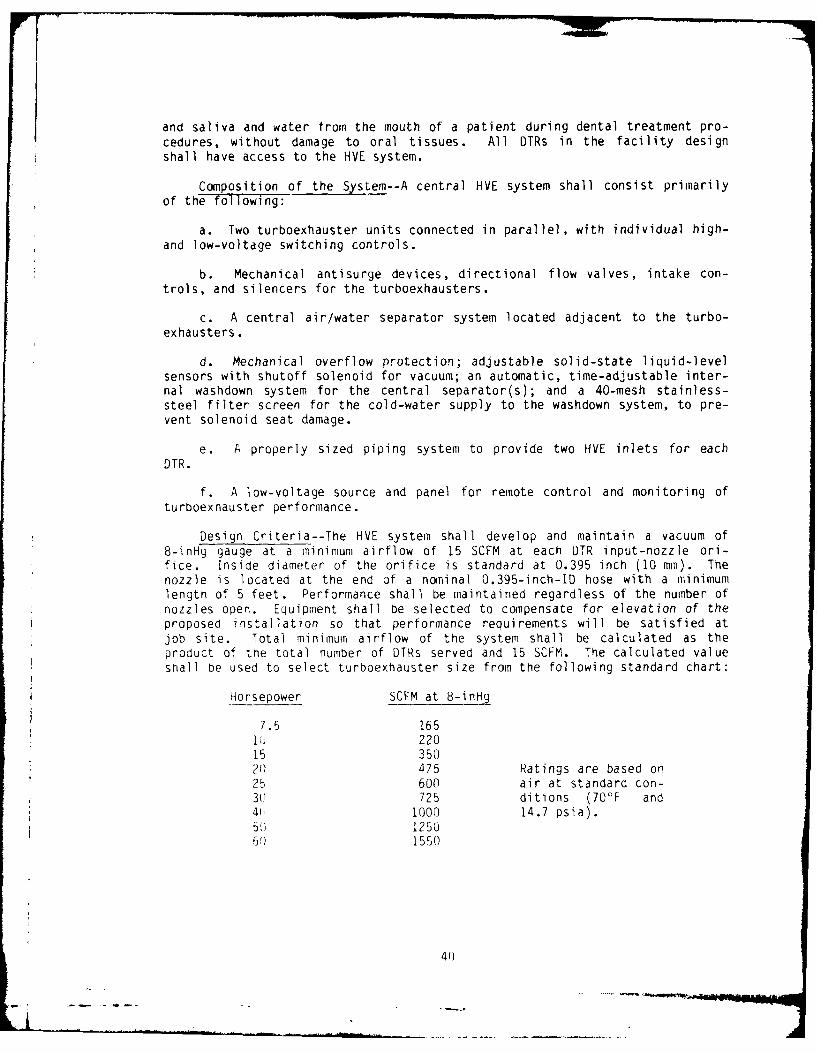
and saliva and water trom the mouth of a patient during dental treatment pro-cedures, without damage to oral tissues. All DTRs in the facility designshall have access to the HVE system.
Composition of the System--A central HVE system shall consist primarilyof the following:
a. Two turboexhauster units connected in parallel, with individual high-and low-voltage switching controls.
b. Mechanical antisurge devices, directional flow valves, intake con-trols, and silencers for the turboexhausters.
c. A central air/water separator system located adjacent to the turbo-exhausters.
d. Mechanical overflow protection; adjustable solid-state liquid-levelsensors with shutoff solenoid for vacuum; an automatic, time-adjustable inter-nal washdown system for the central separator(s); and a 40-mesh stainless-steel filter screen for the cold-water supply to the washdown system, to pre-vent solenoid seat damage.
e. A properly sized piping system to provide two HVE inlets for eachDTR.
f. A low-voltage source and panel for remote control and monitoring ofturboexnauster performance.
Design Criteria--The HVE system shall develop and maintain a vacuum of8-inHg gauge at a minimum airflow of 15 SCFM at each DTR input-nozzle ori-fice. Inside diameter of the orifice is standard at 0.395 inch (10 mm). Thenozzle is located at the end of a nominal 0.395-inch-ID hose with a minimumlengtn of 5 feet. Performance shall be maintained regardless of the number ofnozzles open. Equipment shall be selected to compensate for elevation of theproposed installation so that performance requirements will be satisfied atjob site. Total minimum airflow of the system shall be calculated as theproduct of the total number of DTRs served and 15 SCFM. The calculated valueshall be used to select turboexhauster size from the following standard chart:
Horsepower SCFM at 8-inHg
7.5 1651J 220i5 35020 475 Ratings are based on25 600 air at standard con-30 725 ditions (70°F and41 1000 14.7 psia).50) 12506 ) 1550
40
9,-,

The HVE system shall have two turboexhausters, each sized to handle 100% ofthe calculated load. Exhauster inputs shall be connected in parallel. Eachinput shall be equipped with a mechanical antisurge valve for vacuum control.The equipment manufacturer shall furnish documented certification of eachturboexhauster as to its ability to handle the design loads without exceedingthe normal operational limits of the exhauster or drive motor. Ingestiongates and antisurge valves shall be preset to maintain specified designrequirements for airflow and vacuum levels. The HVE system shall incorporateone or several central separators as determined by the following criteria:
No. of DTRs Separator tanksQuantity Size gaI.
1-6 1 207-10 1 40
11-20 1 8021-30 2 4031 and above 2 80
When multiple separators are used, tank inputs and tank exhausts shall be con-nected in parallel, and liquid-level sensors shall be set to effect drainageat a different level for each tank so that evacuator service to the facilityshall not be interrupted.
High-Vacuum Oral Evacuation System (HIVAC) for Oral Surgery,Periodontics, and Endodontics Treatment Rooms
General Information--The KIVAC system produces higher vacuum power(inHg) at a much reduced volume (CFM) than the HVE system. The HIVAC systemis designed for use with small-orifice surgical aspirator tips (0.062-inch ID)compared to the larger tips kO.5-inch ID) of the HVE. These smaller tips,operating at 15-20 inHg and 1-2 CFM, are required for safe removal of fluids,sutures, and hard- and soft-tissue debris without damage to viable tissues andwithout dislodgement of freshly formed blood clots during surgical proce-dures. The HIVAC function shall be furnished, in addition to the HVE, to allDTRs designated for oral surgery, periodontics, and endodontics and to DTRsdedicated to support General Dentistry Resident Programs in trainingfacilities. The system shall be of essentially dry _onfiguration, withregulators, transparent separators, and overflow protectors at each DTR input.
Composition of the System--The r,'VAC system shall consist primarily ofthe following:
a. A pair of dual-rotor water-ring (water-injected/water-seal) pumps inparallel, with high- and low-voltage switching controls.
b. A vacuum vessel (tank) equipped with vacuum sensors and associatedswitches for maintaining vacuuL within the tank at between 15 and 20 inHg.The tank shall be corrosion resistant and equipped with a nanual drain andother plumbinq and devices written or implied in the specification.
41
- -

c. Silencer (muffler) for the common exhaust line of the pumps.
d. Duplex magnetic starter with alternating feature.
e. Low-voltage source and control panel for remote control, with per-formance indicators for the system.
f. Each DTR inlet shall terminate with a wall-mounted quick-connect/disconnect fitting and be provided with a mating fitting carrying an adjust-able vacuum regulator; a transparent separator container with float (minimum 2liters); an overflow protection device (foamproof); a suction-hose input barb;a suction hose (minimum 5-foot length); three aspirating tips with 0.125-inch(3.18 mm) ID; and three aspirating tips with 0.062-inch (1.6 mm) ID.
Design Criteria--The HIVAC pumps shall individually produce and maintaina vacuum range of 15-20 inHg in the reservoir. Vacuum sensors and switches onthe reservoir shall activate the duplex automatic alternating magnetic starterto start up the pump at 15-inHg vacuum level in the reservoir and shut downthe pump at 20-inHg vacuum level. Each inlet regulator shall be capable ofregulating air volume, at a range of 1-3 CFM, through a 0.125-inch-ID (3.18Mm) surgical aspirator tip. Pumps shall be installed in pairs, withindividual pump capacity sufficient to produce the above-specified vacuum(inHg) and airflow (CFM), based on a 60% use factor for the entire system.Pumps shall be sized according to the following as minimum requirements:
No. of DTRs Single pump HP
1-6 17-12 213-20 321-36 537-60 7.5
High-Volume Evacuation System forBase Dental Laboratories (HVEL)
General Information--The HVEL system scavenges and centrally separates,fi Iters, and collects material trimmings, grinding debris (toxic andnontoxic), 6nd particulates from polishing and finishing operations in thedental laboratory. All air-abrasive, cutting, grinding, and finishingequipment, both portable and stationary, shall have input to the system.'Airflow volume shall be su'ficient to scavenge these devices to preventcontamination of the laboratory environment. The HVEL system shall exhaust tothe atmosphere outside of the laboratory building.
Composition of the System--The HVEL system shall consist primarily of thefol lowing:
a. One turboexhauster complete with high- and low-voltige switching con-trols. a preset field-adjustable ingestion valve, and exhaust silencer.
42
• ... "-.4

b. A central cyclonic separator with a filter-bag system.
c. A low-voltage source and remote control panel for remote control andindication of turboexhauster performance.
d. A properly sized piping system to provide one HVEL inlet per techni-cian and other inlets as indicated for equipment specified in the laboratorydesign.
e. A mechanically operating air volume relief valve, sensitive to nega-tive air pressure to regulate inlet flow rate and equipped with a silencer.
Design Criteria--The HVEL system shall develop and maintain a vacuum of3-inHg gauge. Total calculated airflow load (SCFM) shall be the sum of 60SCFM per technician and 150 SCFM for each unit of equipment specified. Thesystem's capacity shall be sized according to the total calculated loadmodified by one of the appropriate use factors given below:
Laboratory size Use factor(No. of technicians)
1-4 605-10 7011-15 8016-24 85
The modified airflow-load value (SCFM) shall be used to select the turbo-exhauster frontthe following standard chart:
Exhauster Airflow Motor/Exhauster(HP) (SCFM) (rpm)
3 400 1725/26005 700 1725/26007.5 1100 1725/2600
10 1600 1725/260015 2200 1725/2600
User inlets for technicians' benches and at equipment locations shall bepositioned on the face of the casework service ledge. Piping shall be routedin the service ledge from designated inlets to the main trunk line and centralseparator. The trunk line shall be extended outside of the facility, with theair volume relief valve ingesting outside air. Capacity of the centralseparator shall be based on the following filter-area requirements:
Laboratory size Filter-separator Primary(No. of technicians) (ft) separator
1-4 60 not required5-10 100 not required11-15 300 not required16-24 300 one required
43

The primary separator required for larger laboratory design shall also be usedin any design, regardless of size, when the specified equipment includes asand-blasting unit without built-in filtration. This additional protection isrequired to prevent damage to the vacuum producer. Sand blasters with built-in filtration may be connected to the central vacuum system without a primaryseparator: This does not preclude the requirement for a primary separator forlarge laboratories (16-24 technicians). Micro finishing air-abrasive devicesusing particle sizes of 50-um diameter and below and shell blasters withoutbuilt-in filtration are exempt from the primary separator requirement.
Environmental-Janitorial Vacuum System (EJVS)
General Information--The EJVS shall provide for safe and effective jani-torial vacuum cleaning throughout the dental facility as well as pickup andtrapping of accidental mercury spills, thus controlling mercury-vapor contami-nation in the staff and patient environment. The system shall also protectuser personnel from accidental mercury-vapor exposure as they clean in areaswhere mercury may collect.
Composition of the System--A central vacuum system shall consist primar-
ily of the following:
a. A vacuum source (HVE turboexhauster(s)).
b. A central dry cyclonic separator with filter bag(s).
c. A properly sized piping system with vacuum inlets at specified loca-tions.
d. Hose(s) and tools for janitorial service.
e. Portable wet caddy(s) with hoses and accessory tools for wet or drycleaning of mercury spills from smooth floor coverings.
Design Criteria--The EJVS shall be powered by the clinic's HVE turboex-hauster system. A vacuum branch line shall be taken off the parallel manifoldbetween exhausters and central wet separator(s). This vacuum branch shallpower a central dry separator located adjacent to the wet separator(s). Sizecapacities for the central dry separator shall be determined by the number ofvacuum inlets used at one time (users). Maximum allowable users shall be cal-culated by the product of total airflow capacity available from the HVE vac-uum: product (No. of DTRs x 15 SCFM + 10% for friction loss) divided by 85SCFM for each user. Separator capacities shall be selected from the followingcriteria:
No. of users at Separator capacities
one time Dirt can (ft Filter area (ft )
1-3 2.5 304-6 3.75 607-9 4.5 90
10 and above 4.5 142
44
.. ... )
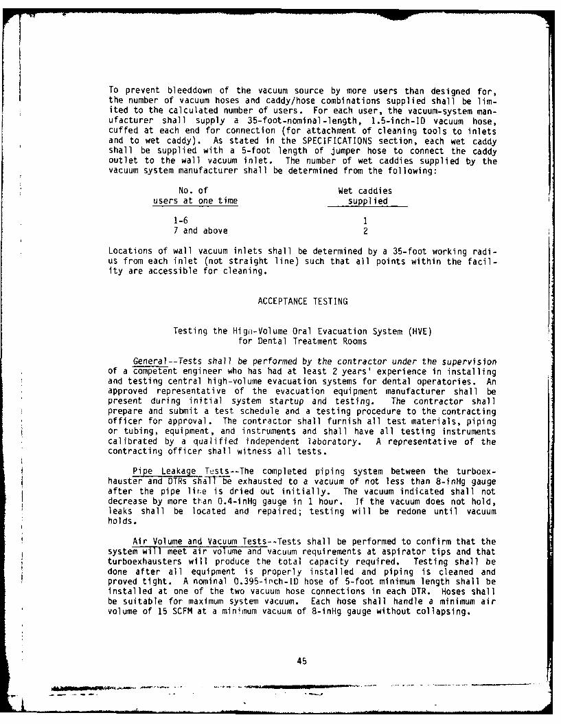
To prevent bleeddown of the vacuum source by more users than designed for,the number of vacuum hoses and caddy/hose combinations supplied shall be lim-ited to the calculated number of users. For each user, the vacuum-system man-ufacturer shall supply a 35-foot-nominal-length, 1.5-inch-ID vacuum hose,cuffed at each end for connection (for attachment of cleaning tools to inletsand to wet caddy). As stated in the SPECIFICATIONS section, each wet caddyshall be supplied with a 5-foot length of jumper hose to connect the caddyoutlet to the wall vacuum inlet. The number of wet caddies supplied by thevacuum system manufacturer shall be determined from the following:
No. of Wet caddiesusers at one time supplied
1-6 17 and above 2
Locations of wall vacuum inlets shall be determined by a 35-foot working radi-us from each inlet (not straight line) such that all points within the facil-ity are accessible for cleaning.
ACCEPTANCE TESTING
Testing the Hign-Volume Oral Evacuation System (HVE)for Dental Treatment Rooms
General--Tests shall be performed by the contractor under the supervisionof a competent engineer who has had at least 2 years' experience in installingand testing central high-volume evacuation systems for dental operatories. Anapproved representative of the evacuation equipment manufacturer shall bepresent during initial system startup and testing. The contractor shallprepare and submit a test schedule and a testing procedure to the contractingofficer for approval. The contractor shall furnish all test materials, pipingor tubing, equipment, and instruments and shall have all testing instrumentscalibrated by a qualified independent laboratory. A representative of thecontracting officer shall witness all tests.
Pipe Leakage Tusts--The completed piping system between the turboex-hauster and DTRs shall be exhausted to a vacuum of not less than 8-inHg gaugeafter the pipe lire is dried out initially. The vacuum indicated shall notdecrease by more than 0.4-inHg gauge in 1 hour. If the vacuum does not hold,leaks shall be located and repaired; testing will be redone until vacuumholds.
Air Volume and Vacuum Tests--Tests shall be performed to confirm that thesystem will meet air volume and vacuum requirements at aspirator tips and thatturboexhausters will produce the total capacity required. Testing shall bedone after all equipment is properly installed and piping is cleaned andproved tight. A nominal 0.395-inch-ID hose of 5-foot minimum length shall beinstalled at one of the two vacuum hose connections in each DTR. Hoses shallbe suitable for maximum system vacuum. Each hose shall handle a minimum airvolume of 15 SCFM at a minimum vacuum of 8-inHg gauge without collapsing.
45

With all DTR hoses fully closed, the first turboexhauster shall be started.Fifteen minutes after startup, the current draw of the turboexhauster drivemotor shall be measured with an appropriate amp meter and recorded with thereading of the remote-panel vacuum gauge. All DTR hoses shall then be fullyopened and the current and vacuum values again recorded. The first turboex-hauster shall then be shut down and the test repeated with the second turboex-nauster on-line. To meet partial contract requirements, the electrical powermeasurements shall not exceed the normal power rating, beyond the fractionalrating, of the drive motor, and the vacuum readings shall at all times bemaintained at 8-inHg gauge, ± 0.2.
Recorded Test Data--Three copies of recorded test data shall be furnishedto the contracting officer.
General Operating Test--A general operating test shall be conducted dur-ing or after air volume and vacuum tests to assure that the exhausters startup properly. In addition, each DTR input shall be tested with at least1 quart of water to assure proper function of individual inputs. Sufficientadditional water shall be ingested into the system to demonstrate the success-ful operation of mechanical overfill protection, the liquid-level sensor/drainage system, and the automatic internal washdown system.
Testing the High-Vacuum Oral Evacuation System (HIVAC) forOral Surgery, Periodontics, and Endodontics Treatment Rooms
General--Tests shall be performed by the contractor under the supervisionof a competent engineer who has had at least 2 years' experience in installingand testing high-vacuum evacuation systems for dental facilities. An approvedrepresentative of the evacuation-equipment manufacturer shall be present dur-ing initial system startup and testing. The contractor shall prepare and sub-mit a testing schedule and a testing procedure to the contracting officer forapproval. The contractor shall furnish all necessary materials, equipment,and instruments and shall have all testing instruments calibrated by a quali-fied independent laboratory. A representative of the contracting officershall witness all tests.
Pipe Leakage Tests--The completed piping system between the high-vacuumpumps and the DTR hose connections shall be exhausted to a vacuum of not lessthan 20-inHg gauge after the pipe line is dried out initially. The vacuum in-dicated shall not decrease by more than O.4-inHg gauge in 1 hour. If the vac-uum does not hold, leaks shall be located and repaired; testing shall be re-done until vacuum holds.
Vacuum Tests--Tests shall be performed to confirm that the system willmeet vacuum requirements at the surgical evacuator tip and that the high-vac-uum pumps are operating per design requirements. A nominal 0.395-inch-ID hoseof 5-foot minimum length shall be installed at each DTR high-vacuum hose con-nection. Hoses shall be suitable for maximum system vacuum of 20-inHg gaugeand airflow of 3 SCFM. Each hose shall be equipped at the nozzle end with asurgical tip (or facsimile thereof) with a nominal 0.125-inch ID. Each pumpshall be tested separately. Testing shall begin after all equipment is prop-erly installed, piping cleaned and proved tight, and the system inspected by
46
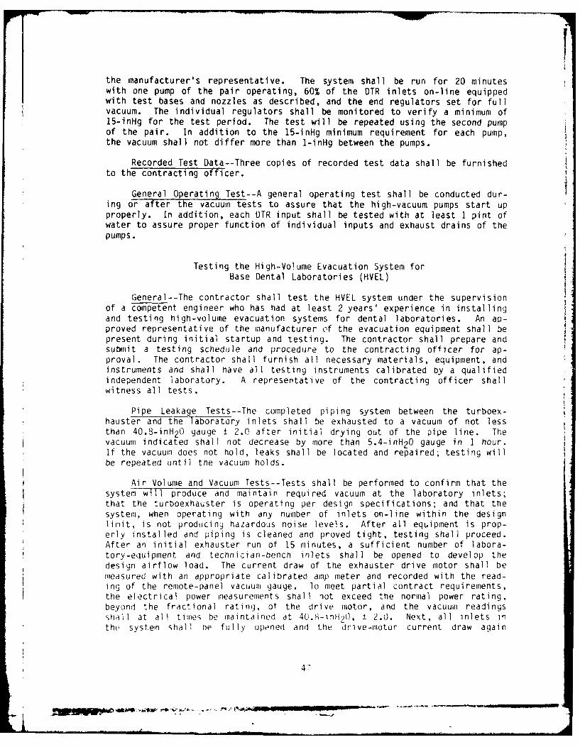
the manufacturer's representative. The system shall be run for 20 minuteswith one pump of the pair operating, 60% of the DTR inlets on-line equippedwith test bases and nozzles as described, and the end regulators set for fullvacuum. The individual regulators shall be monitored to verify a minimum of15-inHg for the test period. The test will be repeated using the second pumpof the pair. In addition to the 15-inHg minimum requirement for each pump,the vacuum shall not differ more than 1-inHg between the pumps.
Recorded Test Data--Three copies of recorded test data shall be furnishedto the contracting officer.
General Operating Test--A general operating test shall be conducted dur-ing or after the vacuum tests to assure that the high-vacuum pumps start upproperly. In addition, each DTR input shall be tested with at least I pint ofwater to assure proper function of individual inputs and exhaust drains of thepumps.
Testing the High-Volume Evacuation System forBase Dental Laboratories (HVEL)
General--The contractor shall test the HVEL system under the supervisionof a competent engineer who has had at least 2 years' experience in installingand testing high-volume evacuation systems for dental laboratories. An ap-proved representative of the manufacturer of the evacuation equipment shall bepresent during initial startup and testing. The contractor shall prepare andsubmit a testing schedule and procedure to the contracting officer for ap-proval. The contractor shall furnish all necessary materials, equipment, andinstruments and shall have all testing instruments calibrated by a qualifiedindependent laboratory. A representative of the contracting officer shallwitness all tests.
Pipe Leakage Tests--The completed piping system between the turboex-hauster and the laboratory inlets shall be exhausted to a vacuum of not lessthan 40.8-inH 20 gauge ± 2.0 after initial drying out of the pipe line. Thevacuum indicated shall not decrease by more than 5.4-inH20 gauge in 1 hour.If the vacuum does not hold, leaks shall be located and repaired; testing willbe repeated until the vacuum holds.
Air Volume and Vacuum Tests--Tests shall be performed to confirm that thesystem will produce and maintain required vacuum at the laboratory inlets;that the turboexhauster is operating per design specifications; and that thesystem, when operating with any number of inlets on-line within the designlimit, is not producing hazardous noise levels. After all equipment is prop-erly installed and piping is cleaned and proved tight, testing shall proceed.After an initial exhauster run of 15 minutes, a sufficient number of labora-tory-equipment and technician-bench inlets shall be opened to develop thedesign airflow load. The current draw of the exhauster drive motor shall bemeasured with an appropriate calibrated amp meter and recorded with the read-ing of the remote-panel vacuum gauge. lo meet partial contract requirements,the electrical power measurements shall not exceed the normal power rating,beyond the fractional rating, of the drive motor, and the vacuum readingsshall at all times be maintained at 4U.,8-inH2 0, ± 2.0. Next, all Inlets inthe system shal I he fully opened and the drive-motor current draw again
47
.. . .. -- - -

recorded. The ingestion-gate adjustment shall be such that at maximum airflowload, the electrical power shall not exceed the motor design limits. Vacuumpower (inH2 0), however, should be expected to fall considerably due to bleed-down of the system; this is acceptable. Finally, a noise-measuring instrumentshall be used to measure high-velocity-air noise 24 inches from the vacuuminlet orifice. Noise shall not exceed current USAF Occupational and Environ-mental Health Laboratory (OEHL) limits as calculated on a time-weighted aver-age (TWA) for an 8-hour work day.
Recorded Test Data--Three copies of recorded test data shall be furnishedto the contracting officer.
General Operating Test--A general operating test shall be conducted dur-ing or after airflow and vacuum tests to assure that (a) the turboexhausterstarts up properly and (b) in the opinion of the inspecting engineer, vibra-tion is not excessive and neither belt nor exhaust-air noise exceeds speci-fication limits.
Testing the Environmental-JanitorialVacuum System (EJVS)
General--The contractor shall perform tests under the supervision of acompetent engineer who has had at least 2 years' experience in installing andtesting central vacuum systems for health facilities. The contractor shallprepare and submit a testing schedule and procedure to the contracting officerfor approval. The contractor shall furnish all necessary materials, equip-ment, and instruments and shall have all testing instruments calibrated by aqualified independent laboratory. A representative of the contracting officershall witness all tests.
Pipe Leakage Tests--Piping and inlets of the central vacuum system shallbe considered a continuing part of the HVE system and shall be leak testedwith the HVE piping.
Air Volume and Vacuum Tests--Air volume and vacuum shall be tested as forthe HVE. Testing shall be done with hoses and/or caddy/hose combinations con-nected to vacuum inlets and with all DTR oral evacuation hoses fully closed.Each vacuum hose shall have a cleaning tool attached while testing. Turboex-hauster motor current readings shall not exceed the power rating of the drivemotor, beyond the fractional limit. The vacuum power shall not be less than7-inHg gauge.
Operating and Maintenance Instructions Requiredfor All Systems
Bound Instructions--Six complete sets of the manufacturer's operating andmaintenance instructions for each piece of equipment shall be furnished thecontracting officer. Each set shall be permanently bound within a hardcover. One complete set shall be furnished at the time the test procedure issubmitted; remaining sets shall be furnished before the contract is com-pleted. The following identification shall be inscribed on the covers: OPER-ATING AND MAINTENANCE INSTRUCTIONS, with name and location of building, name
48
-- a --.- "-'
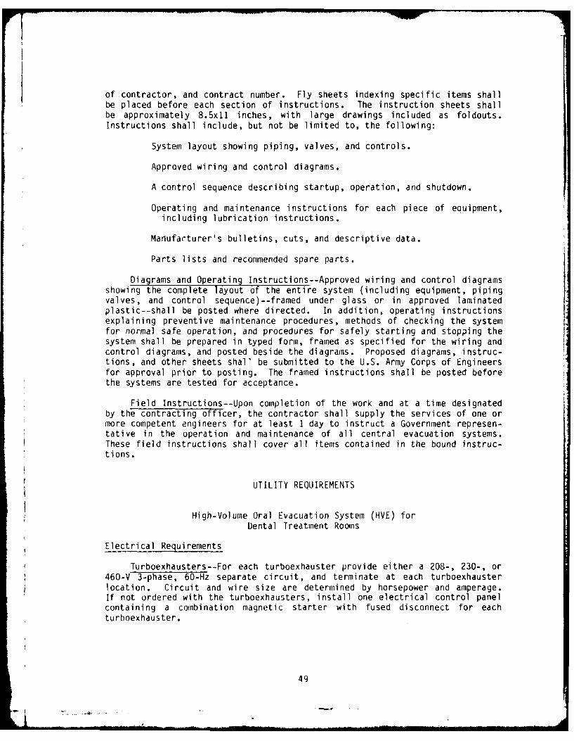
of contractor, and contract number. Fly sheets indexing specific items shallbe placed before each section of instructions. The instruction sheets shallbe approximately 8.5x11 inches, with large drawings included as foldouts.Instructions shall include, but not be limited to, the following:
System layout showing piping, valves, and controls.
Approved wiring and control diagrams.
A control sequence describing startup, operation, and shutdown.
Operating and maintenance instructions for each piece of equipment,including lubrication instructions.
Manufarturer's bulletins, cuts, and descriptive data.
Parts lists and recommended spare parts.
Diagrams and Operating Instructions--Approved wiring and control diagramsshowing the complete layout of the entire system (including equipment, pipingvalves, and control sequence)--framed under glass or in approved laminatedplastic--shall be posted where directed. In addition, operating instructionsexplaining preventive maintenance procedures, methods of checking the systemfor normal safe operation, and procedures for safely starting and stopping thesystem shall be prepared in typed form, framed as specified for the wiring andcontrol diagrams, and posted beside the diagrams. Proposed diagrams, instruc-tions, and other sheets shall be submitted to the U.S. Army Corps of Engineersfor approval prior to posting. The framed instructions shall be posted beforethe systems are tested for acceptance.
Field Instructions--Upon completion of the work and at a time designatedby the contracting officer, the contractor shall supply the services of one ormore competent engineers for at least I day to instruct a Government represen-tative in the operation and maintenance of all central evacuation systems.These field instructions shall cover all items contained in the bound instruc-tions.
UTILITY REQUIREMENTS
High-Volume Oral Evacuation System (HVE) for
Dental Treatment Rooms
Electrical Requirements
Turboexhausters--For each turboexhauster provide either a 208-, 230-, or460-V 3-phase, 60-Hz separate circuit, and terminate at each turboexhausterlocation. Circuit and wire size are determined by horsepower and amperage.If not ordered with the turboexhausters, install one electrical control panelcontaining a combination magnetic starter with fused disconnect for eachturboexhauster.
49

Horsepower Voltage Amps
7.5 208 V, 3 D 197.5 230 V, 3 o 187.5 460 V, 3 o 9
10 208 V, 3 o 2710 230 V, 3 D 2610 460 V, 3 o 13
15 208 V, 3 D 3815 230 V, 3 o 3715 406 V, 3 o 19
20 208 V, 3 o 5320 230 V, 3 o 5220 406 V, 3 o 26
25 208 V, 3 D 6325 230 V, 3 t 6225 406 V, 3 o 31
30 208 V, 3 o 7430 230 V, 3 D 7330 406 V, 3 o 37
Turboexhausters' Remote Control Panel--Install a remote control pan-el--complete with vacuum gauge, dual 120-V on-off switches, and indicatorlights--in dental clinic area for remote control of the turboexhausters. Fromremote control panel location, run six #14 color-coded wires to turboexhausterelectrical control panel. Run three wires from switch 1 to turboexhauster 1and three wires from switch 2 to turboexhauster 2. Hook up control wires tocoil of magnetic starter for each turboexhauster.
Autoflush--For autoflush assembly provide a 115-V electrical outlet on aseparate 15- or 20-A circuit. Autoflush timeclock should be set to come on at0100 and shut off at 0200. Recheck time setting once a week to be sure time-clock is set properly. Always reset timeclock after a power failure or ifcircuit has been shut off. Flushing must not take place when turboexhaustersare in operation.
Water Requirements
Liquid Separator--The separator tank requires a floor sink 12x12x6 inchesdeep. The sink should discharge through a minimum 3-inch-diameter drain tothe sanitary sewer, not to a storm drain. The tank drain can be plumbed to anexistino floor sink if necessary; however, in new construction or retrofitprojects, a floor sink under or near the tank is good practice. Because ofobvious complications should pump failure occur, in-line or sump pumps shouldbe used only as a last resort for the removal of drained effluent.
Autoflush' for Liquid Separator--At autoflush location provide a 0.5-inchcold water line, fitted with a (.5-inch FPT gate valve, for connection to asolenoid valve and 40-mesh filter on the autofILIsh.
50

High-Vacuum Oral Evacuation System (HIVAC) forOral Surgery, Periodontics, and Endodontics Treatment Rooms
Electrical Requirements--Power must be provided for each pump. Circuitsize may be determined from the following:
Horsepower(each pump) Voltage Amps
1 2 110 V, 1 €14
220 V, 1 7208 V, 3 12230 V, 3 12460 V, 3 o 6
3 208 V, 3 8.8230 V, 3 8.8460 V, 3 4.4
5 208 V, 3 13230 V, 3s 13460 V, 3 7
7.5 208 V, 3 r 20230 V, 3 20460 V, 3 10
A separate 11O-VAC, 15-A circuit must be available at the location of theelectrical control panel to power the low-voltage power supply for the remotecontrol circuit.
Water Requirements--A 0.75-inch cold water supply line with a 0.75-inchmanual gate valve is required at the pump/reservoir location to provide sealwater for the pumps.
Drain Requirements--A floor sink with minimum dimensions of 12x12x6
inches deep with a 2-inch-minimum-diameter drain to the sanitary sewer isrequired at or very near the pump/reservoir location. The expulsion of sealwater is continuous from each pump while running. The drainage should notcontain waste products if the clinical end items are properly used.
Vent Requirements--The exhausted mixture of air and seal water from thepumps passes through a separator immediately after leaving the pump outlet. A3-inch-minimum-diameter plumbing vent stack is required at the pump/reservoirlocation to vent separated air to atmosphere outside the facility.
High-Volume Evacuation System forBase Dental Laboratories (HVEL)
Electrical Requirement: Turboexhauster (Belt Drive)--For turboexhaustersprovide a 208/230/460-V, 3-phase, 60-Hz separate circuit, and terminate at theturboexhauster location. Circuit and wire size are determined by horsepower
51- - - - - - - - -- -.-- -- m
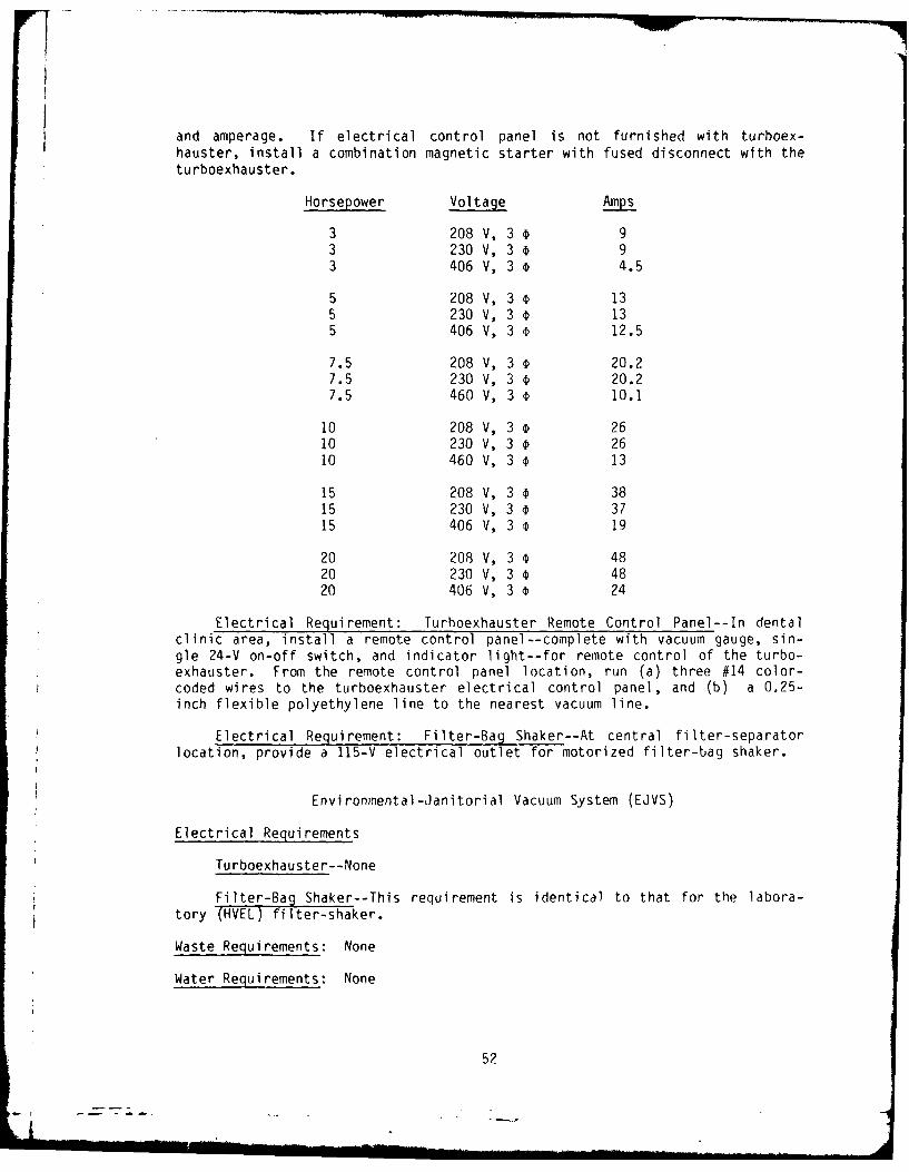
and amperage. If electrical control panel is not furnished with turboex-hauster, install a combination magnetic starter with fused disconnect with theturboexhauster.
Horsepower Voltage Amps
3 208 V, 3 93 230 V, 3 93 406 V, 3 ¢ 4.5
5 208 V, 3 135 230 V, 3 135 406 V, 3 s 12.5
7.5 208 V, 3 € 20.27.5 230 V, 3 @ 20.27.5 460 V, 3 € 10.1
10 208 V, 3 2610 230 V, 3 2610 460 V, 3 13
15 208 V, 3 3815 230 V, 3 ¢ 3715 406 V, 3 19
20 208 V, 3 4820 230 V, 3 D 4820 406 V, 3 o 24
Electrical Requirement: Turhoexhauster Remote Control Panel--In dentalclinic area, install a remote control panel--complete with vacuum gauge, sin-gle 24-V on-off switch, and indicator light--for remote control of the turbo-exhauster. From the remote control panel location, run (a) three #14 color-coded wires to the turboexhauster electrical control panel, and (b) a 0.25-inch flexible polyethylene line to the nearest vacuum line.
Electrical Requirement: Filter-Bag Shaker--At central filter-separatorlocation, provide a 115-V electrical outlet for motorized filter-bag shaker.
Environmental-Janitorial Vacuum System (EJVS)
Electrical Requirements
Turboexhauster--None
Filter-Bag Shaker--This requirement is identical to that for the labora-tory (HVEL) filter-shaker.
Waste Requirements: None
Water Requirements: None
52
- I -i:

GLOSSARY
ABS Acrylonitrile butyl styrene.
CFM Cubic feet per minute (0.028 m3/min); used as the unit of volumeof air delivered (airflow).
Dripproof An electric motor with a housing so designed that dripping liq-uids cannot enter the housing to affect performance.
DWV Drain, waste, and vent.
FPM Feet per minute (0.3048 m/min); the unit of velocity of air move-ment, which describes the speed of a molecule of air in the massof moving air.
FPT Female pipe thread.
GRP Glass-reinforced plastic.
inHg Inches of mercury; the unit of vacuum pressure which representsthe negative pressure required to lift a column of mercury 1 inch(2.54 cm) in the containing glass tube (1 inHg = 13.6 inH20).
MPT Male pipe thread.
NEMA National Electrical Manufacturers Association. Electric motorsthat carry the NEMA frame designation are constructed to meet di-mensional standards set by the industry.
PVC Polyvinyl chloride.
rpm Revolutions per minute; the unit of rotary speed for spinningbodies.
SCFM Standard cubic feet per minute (at standard air conditions of14.7 psia and 700F, or 210C).
Stub The outer end of a central pipe network.
T-frame A totally enclosed electric motor housing to protect againstdust, dirt, and dampness.
VAC Volts alternating current. For CONUS installations, the fre-quency of alternating current is 60 Hz. Out-of-CONUS installa-tions may require 50-Hz equipment.
53
a .. . .. " . .. .

,DATE
ILMEI