FG-200 HSE/FF Modbus - Softing...FG-200 HSE/FF Modbus User Manual Version: EN-022020-1.30.1 Softing...
80
© Softing Industrial Automation GmbH FG-200 HSE/FF Modbus User Manual Version: EN-022020-1.30.1
Transcript of FG-200 HSE/FF Modbus - Softing...FG-200 HSE/FF Modbus User Manual Version: EN-022020-1.30.1 Softing...

© Softing Industrial Automation GmbH
FG-200 HSE/FF Modbus
User Manual
Version: EN-022020-1.30.1
Softing Industrial Automation GmbH
Richard-Reitzner-Allee 685540 Haar / Germanyhttps://industrial.softing.com
+ 49 89 4 56 56-340+ 49 89 4 56 [email protected]@softing.com
Scan the QR code to find the latest documentation on the product web page under Downloads.
Disclaimer of liabilityThe information contained in these instructions corresponds to the technical status at the time of printing of it and is passed on with thebest of our knowledge. Softing does not warrant that this document is error free. The information in these instructions is in no event abasis for warranty claims or contractual agreements concerning the described products, and may especially not be deemed as warrantyconcerning the quality and durability pursuant to Sec. 443 German Civil Code. We reserve the right to make any alterations orimprovements to these instructions without prior notice. The actual design of products may deviate from the information contained inthe instructions if technical alterations and product improvements so require.
Trademarks
FOUNDATION™ and HART® are marks of the FieldComm Group of Austin, Texas, USA.Modbus® is a registered trademark of Schneider Electric, licensed to the Modbus Organization, Inc.
OpenSource
To comply with international software licensing terms, we offer the source files of open source software used in our products. For detailssee https://opensource.softing.com/
If you are interested in our source modifications and sources used, please contact: [email protected]
Version EN-022020-1.30.1 3
Table of Contents
Table of Contents
Chapter 1 ...................................................................................... 7About this guide
............................................................................................................... 71.1 Read me first
............................................................................................................... 71.2 Target audience
............................................................................................................... 71.3 Typographic conventions
............................................................................................................... 81.4 Document history
............................................................................................................... 81.5 Related documentation
............................................................................................................... 81.6 Document feedback
Chapter 2 ...................................................................................... 9About FG-200 HSE/FF Modbus
............................................................................................................... 92.1 Intended use
............................................................................................................... 92.2 Specifications
............................................................................................................... 92.3 System requirements
............................................................................................................... 102.4 Safety precautions
Chapter 3 ...................................................................................... 11Installation
............................................................................................................... 113.1 Hardware installation
.......................................................................................................... 11Installation in hazardous locations 3.1.1
..................................................................................................... 11General requirements3.1.1.1
..................................................................................................... 13Hazardous Location - European and International Approval (ATEX, IECEx)3.1.1.2
..................................................................................................... 14Hazardous Location - North American Approval (cULus)3.1.1.3
.......................................................................................................... 15Mounting and dismounting 3.1.2
.......................................................................................................... 16Connection diagram 3.1.3
.......................................................................................................... 16Connecting the power supply 3.1.4
.......................................................................................................... 17Installation positions 3.1.5
.......................................................................................................... 19Connecting to the network 3.1.6
.......................................................................................................... 20Modbus serial connection 3.1.7
.......................................................................................................... 21Using two FG-200 3.1.8
.......................................................................................................... 22Connecting FF-H1 interfaces 3.1.9
.......................................................................................................... 22Powering up the device 3.1.10
.......................................................................................................... 23Adding a second FG-200 to form a redundant set of FG-200 3.1.11
............................................................................................................... 243.2 Software installation
Chapter 4 ...................................................................................... 25Configuration
Chapter 5 ...................................................................................... 26Working with the FG-200 HSE/FF Modbus
............................................................................................................... 265.1 FG-200 acts as a Modbus / FF-H1 Gateway
.......................................................................................................... 26FG-200 acts as link active scheduler 5.1.1
.......................................................................................................... 26FG-200 acts as visitor host 5.1.2
Version EN-022020-1.30.1
Table of Contents
4
.......................................................................................................... 27Configuring the Modbus mapping table 5.1.3
.......................................................................................................... 28Modbus statistics counter 5.1.4
............................................................................................................... 295.2 FG-200 acts as a FF-HSE/ FF-H1 gateway
.......................................................................................................... 29FG-200 acts as an H1 interface used by Emerson AMS System 5.2.1
Chapter 6 ...................................................................................... 31Using the web interface
............................................................................................................... 316.1 Login to webserver
............................................................................................................... 326.2 Information menu
............................................................................................................... 336.3 Diagnostics menu
.......................................................................................................... 33System 6.3.1
.......................................................................................................... 33Internet Protocol 6.3.2
.......................................................................................................... 34Fieldbus 6.3.3
.......................................................................................................... 34Advanced 6.3.4
............................................................................................................... 356.4 Monitor menu
.......................................................................................................... 35Point Pages submenu 6.4.1
.......................................................................................................... 35Point Data submenu 6.4.2
............................................................................................................... 366.5 Configuration menu
.......................................................................................................... 36Settings 6.5.1
..................................................................................................... 36General Settings submenu6.5.1.1
..................................................................................................... 38Internet Protocol submenu6.5.1.2
..................................................................................................... 39LD Settings submenu6.5.1.3
..................................................................................................... 39User Accounts submenu6.5.1.4
.......................................................................................................... 41System Maintenance 6.5.2
..................................................................................................... 41Restart submenu6.5.2.1
..................................................................................................... 41Firmware submenu6.5.2.2
..................................................................................................... 42Configuration Backup submenu6.5.2.3
..................................................................................................... 43Time submenu6.5.2.4
.......................................................................................................... 44Page Options 6.5.3
..................................................................................................... 44Point Pages submenu6.5.3.1
..................................................................................................... 45Point Columns submenu6.5.3.2
..................................................................................................... 46Homepage submenu6.5.3.3
.......................................................................................................... 46Fieldbus 6.5.4
..................................................................................................... 46Devices submenu6.5.4.1
..................................................................................................... 47Blocks submenu6.5.4.2
..................................................................................................... 48H1 Busparameter submenu6.5.4.3
..................................................................................................... 48HSE submenu6.5.4.4
.......................................................................................................... 49Modbus 6.5.5
..................................................................................................... 49Communication submenu6.5.5.1
..................................................................................................... 50Import/Export submenu6.5.5.2
Version EN-022020-1.30.1 5
Table of Contents
Chapter 7 ...................................................................................... 51Redundancy mode
............................................................................................................... 517.1 Redundancy concept
............................................................................................................... 527.2 Fault domain
............................................................................................................... 557.3 Configuration of a redundant pair of FG-200
Chapter 8 ...................................................................................... 56LED status indicators
............................................................................................................... 568.1 PWR - power supply
............................................................................................................... 578.2 Device LED statuses (PWR, RUN, ERR and RDL) in stand-alone mode
............................................................................................................... 588.3 RUN / ERR / RDL - LED statuses in redundant mode
............................................................................................................... 598.4 Status indications of the four H1 channels
Chapter 9 ...................................................................................... 60Appendix
............................................................................................................... 609.1 FOUNDATION Fieldbus basics
.......................................................................................................... 60Link active scheduler 9.1.1
.......................................................................................................... 60Visitor host 9.1.2
.......................................................................................................... 60Live list 9.1.3
.......................................................................................................... 60Publisher/subscriber links (PUB/SUB links) 9.1.4
.......................................................................................................... 61Client/server connections (CTL/SRV connections) 9.1.5
.......................................................................................................... 61Macrocycle 9.1.6
.......................................................................................................... 61Input/output parameters (I/O parameters) 9.1.7
.......................................................................................................... 61Contained parameters 9.1.8
............................................................................................................... 619.2 Redundancy
.......................................................................................................... 61Redundancy behavior 9.2.1
..................................................................................................... 62Primary device failure (1)9.2.1.1
..................................................................................................... 62Ethernet cable broken (2)9.2.1.2
..................................................................................................... 62H1 cable broken (3)9.2.1.3
..................................................................................................... 63Secondary device failure (4)9.2.1.4
..................................................................................................... 63Ethernet cable broken (5)9.2.1.5
..................................................................................................... 63H1 cable broken (6)9.2.1.6
..................................................................................................... 63TCP connection lost (7)9.2.1.7
..................................................................................................... 64Redundancy link broken or removed (8)9.2.1.8
..................................................................................................... 64State indication associated9.2.1.9
.......................................................................................................... 66Duration of redundancy switch-over 9.2.2
.......................................................................................................... 66Replace a defective FG-200 in a redundant set 9.2.3
............................................................................................................... 689.3 Diagnostics - Advanced submenus
.......................................................................................................... 68Fieldbus Statistics submenu 9.3.1
.......................................................................................................... 68HSE Statistics submenu 9.3.2
.......................................................................................................... 69FPGA Error Statistics submenu 9.3.3
.......................................................................................................... 70FPGA Register Contents submenu 9.3.4
Version EN-022020-1.30.1
Table of Contents
6
.......................................................................................................... 70Device Temperature submenu 9.3.5
.......................................................................................................... 70Modbus Statistics submenu 9.3.6
............................................................................................................... 719.4 Coding of bit fields
............................................................................................................... 729.5 Modbus exception responses
............................................................................................................... 739.6 Assign a second (local) IP address under Windows 8.1
Chapter 10 ...................................................................................... 74ATEX Type Examination Certificate
Chapter 11 ...................................................................................... 77UL Certificate of Compliance
Chapter 12 ...................................................................................... 78Declarations of conformity
Chapter 1 - About this guide
Version EN-022020-1.30.1 7
1 About this guide
1.1 Read me first
Please read this guide carefully before using the device to ensure safe and proper use. Softing does notassume any liability for damages due to improper installation or operation of this product.
This document is not warranted to be error-free. The information contained in this document is subject tochange without prior notice. To obtain the most current version of this guide, visit the Download Center onour website at: http://industrial.softing.com/en/downloads
1.2 Target audience
This guide is intended for experienced operation personnel and network specialists responsible forconfiguring and maintaining field devices in process automation networks. Any person using a FG-200 HSE/FF Modbus must have read and fully understood the safety requirements and working instructions in thisguide.
1.3 Typographic conventions
The following conventions are used throughout Softing customer documentation:
Keys, buttons, menu items, commands and otherelements involving user interaction are set inbold font and menu sequences are separated byan arrow
Open Start Control Panel Programs
Buttons from the user interface are enclosed inbrackets and set to bold typeface
Press [Start] to start the application
Coding samples, file extracts and screen output isset in Courier font type
MaxDlsapAddressSupported=23
Filenames and directories are written in italic Device description files are located in C:\<Application name>\delivery\software\Device Description files
CAUTION
CAUTION indicates a potentially hazardous situation which, if not avoided, may result in minoror moderate injury.
Note
This symbol is used to call attention to notable information that should be followed duringinstallation, use, or servicing of this device.
Hint
This symbol is used when providing you with helpful user hints.

FG-200 HSE/FF Modbus - User Manual
8 Version EN-022020-1.30.1
1.4 Document history
Document version Changes since last version
1.00 First version
1.01 Installation in hazardous locations :
- Introduction restructured and subsections implemented.
- Preliminary information restrictions in hazardous locations deleted.
- Certificate for cULus added .
New section with certificate copy of UL certificate UL Certificate ofCompliance .
1.02 New Corporate Identity implemented.
1.20 References to FF-CONF replaced with comConf. Instructions to Modbusmapping and related chapters removed.
1.30 New layout and structure of chapters. Simplified mounting, dismountingand configuration instructions. Additional trademark references. Software installation procedure updated.
1.30.1 New image of power supply pin assignment . Minor editorial changes.
1.5 Related documentation
The following documents provide additional product information:
Communication Configuration Tool - User Guide
FG-200 HSE/FF Modbus - Datasheet
1.6 Document feedback
We would like to encourage you to provide feedback and comments to help us improve thedocumentation. You can write your comments and suggestions to the PDF file using the editing tool inAdobe Reader and email your feedback to [email protected].
If you prefer to write your feedback directly as an email, please include the following information withyour comments:
document name
document version (as shown on cover page)
page number
11
14
77
16

Chapter 2 - About FG-200 HSE/FF Modbus
Version EN-022020-1.30.1 9
2 About FG-200 HSE/FF Modbus
The Softing FG-200 HSE/FF Modbus is a gateway connecting Modbus RTU, Modbus TCP or FOUNDATIONfieldbus High Speed Ethernet (HSE) to FOUNDATION fieldbus H1 field devices. It provides fast access toprocess data, while making use of FOUNDATION Fieldbus advantages such as reduced cabling, central fielddevice parametrization, comprehensive diagnostics or intrinsically safe device segments. For simpleinstallation it is compatible with the R. STAHL bus-Carrier Series 9419 and Fieldbus power supplies Series9412.
2.1 Intended use
The FG-200 can be used for integrating up to four FF H1 links into a Modbus control system (TCP or RTU) orfor communication between FF H1 devices and FF HSE network. The gateway can be operated in bothhazardous and non-hazardous areas. Any other use is not intended. Follow the instructions in this guide onhow to use the FG-200.
2.2 Specifications
Power supply 18 VDC...32 VDC; SELV/PELV supply mandatory
Typical input current is 200 mA; maximum is 1 A (considering the rush-incurrent at switch-on).
FF-H1 Four FF-H1 channels, compliant with type 114 of the FF physical layer profile.
The Fieldbus voltage range is from 9 VDC...32 VDC. Preferred value is 24 VDC.
Ethernet IEEE 802.3 100BASE-TX/10BASE-T
Minimum ambientoperating temperature
-40 °C (see Installation positions for the maximum ambient temperaturedepending on the mounting position)
Storage temperature -40 °C...+85 °C
Relative humidity 10 %...95 % (non-condensing)
Altitude Must not exceed 2,000 m
Location Indoor use only; no direct sunlight
Coating Conformal Coating based on ANSI/ISA-S71.04 G3
Safety standard IEC/EN/UL 61010-1 Safety requirements for electrical equipment formeasurement, control and laboratory use - Part 1: General requirements
IEC/EN/UL 61010-2-201 Safety requirements for electrical equipment formeasurement, control and laboratory use - Part 2-201: Particularrequirements for control equipment (both with CB scheme).
Ingress protection IP20
2.3 System requirements
24V power supply
power conditioner
PC with operating system Windows 7 or Windows 8.1 (both 32 bit or 64 bit supported)
Web browser (Microsoft Internet Explorer version 8.0 or higher, Mozilla Firefox version version 35 orhigher)
17
FG-200 HSE/FF Modbus - User Manual
10 Version EN-022020-1.30.1
2.4 Safety precautions
Use in hazardous areas
The FG-200 is an electrical equipment with degree of protection Ex nA, approved for use in Zone 2hazardous areas or in the safe area. The four FF-H1 interfaces are designed according to the protectionmethod Ex ic. Only certified circuits with an according protection method shall be connected to these FF-H1 interfaces.
Special hints for safe use
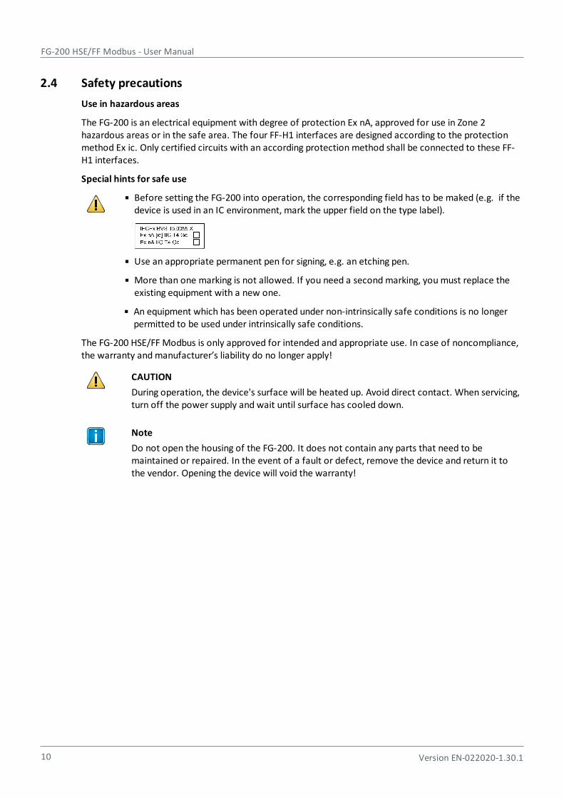
Before setting the FG-200 into operation, the corresponding field has to be maked (e.g. if thedevice is used in an IC environment, mark the upper field on the type label).
Use an appropriate permanent pen for signing, e.g. an etching pen.
More than one marking is not allowed. If you need a second marking, you must replace theexisting equipment with a new one.
An equipment which has been operated under non-intrinsically safe conditions is no longerpermitted to be used under intrinsically safe conditions.
The FG-200 HSE/FF Modbus is only approved for intended and appropriate use. In case of noncompliance,the warranty and manufacturer’s liability do no longer apply!
CAUTION
During operation, the device's surface will be heated up. Avoid direct contact. When servicing,turn off the power supply and wait until surface has cooled down.
Note
Do not open the housing of the FG-200. It does not contain any parts that need to bemaintained or repaired. In the event of a fault or defect, remove the device and return it tothe vendor. Opening the device will void the warranty!

Chapter 3 - Installation
Version EN-022020-1.30.1 11
3 Installation
3.1 Hardware installation
Note
With an ambient temperature above 55 °C at the place of installation it is likely that thetemperatures of connecting cables will increase if the cables are installed in an unfavourableposition. In such cases, measure the temperature to ensure that the service temperature ofthe cables is not exceeded (i.e. 80 °C), or use cables sustaining high temperatures of at least90 °C.
3.1.1 Installation in hazardous locations
The FG-200 HSE/FF Modbus can be used in hazardous locations and is certified according to ATEX, IEC andNorth America Approval cULus.
WARNING
Use only according to operating conditions from instructions!
Use the FG-200 in accordance with its designated use only! Otherwise, the manufacturer’sliability and warranty will expire. The device is only to be used according to the operatingconditions described in these instructions.
WARNING
Do not connect or disconnect energizedconductors!
Be aware that energized conductors are not to beconnected or disconnected! This can lead to dangerof life if potentially explosive atmosphere is presentthere at that time!
Following general requirements must be observed while installing FG-200 on hazardous locations:
The details of this document must be observed along with the conditions for use and the applicabledetails stated on the marking and type labels of each.
Any selection and operation of the device must be done as per the technical rules.
Adequate precautions must be taken to prevent unintended actuation or impairment of the device.
Connectors must not be connected or disconnected when area is known to be hazardous. This can belife threatening in a potentially explosive atmosphere. Open or not securely closed sockets shall not beenergized in the Ex-atmosphere!
Ensure the installed equipment comply with the types of protection applicable to the correspondingzones.
All connected electrical equipment must be suitable for the respective intended use.
FG-200 HSE/FF Modbus - User Manual
12 Version EN-022020-1.30.1
The operator must ensure protection against lightning in compliance with the locally applicableregulations.
Electrostatic aspects must be considered when mounting the bus-modules. Electrostatic charges haveto be prevented.
In explosion group IIC and Zone 2 no protected plastic surfaces > 20 cm2 are allowed; in IIB or dust-Ex,100 cm2 may be reached.
The hazard of any objects falling onto the bus-module must be prevented.
The FG-200 does not meet the requirements of impact protection and IP54 (according to IEC 60529). Itmust be installed in a protective enclosure which meets the requirements for resistance to impact andIP as stated in section 26.4 of IEC/EN 60079-0. This enclosure must be fully mounted and intact. If theenclosure is damaged, the operation is not permitted.
The FG-200 is defined as instruments and apparatus of low energy according to clause 23 of IEC/EN60079-15; thus the requirement stated in sub-clause C, limiting the transient characteristic to 40%above the rated voltage, has to be adhered to when erecting the equipment.
When removing the packaging ensure that no dirt can enter the enclosure or the plugs.
If any vibration during the operation may cause parts of the plugs to loosen, then the plugs have to beprovided with a light firm varnish used for securing screws. An extraction force of 0.5 Nm has to beachieved at an equivalent thread.
To circuits of Zone 2 only such equipment may be connected that is suitable for operation in this zoneand has been certified accordingly.
Components may only be replaced by original spare parts which are also approved for the use in Ex-atmospheres. Spare parts are ordered as complete units giving the material number stated on thedevice (marking, type label).
Only such auxiliary components may be used in potentially explosive atmospheres which meet allrequirements of European and national directives and legislation.
The environmental conditions specified in the manual have to be followed strictly.
The FG-200 is not to be used in systems where cathodic systems for corrosion protection are in place.Although special precautions may allow the use in such systems (additional earthing bridges), themanufacturer has to be consulted in each case.
The operator has to provide measures for protection against lightning.
According to the local conditions and in compliance with the environmental rules, the operator isresponsible to visually inspect the system and to remove dust settlements in a regularly interval (every6 months).
The company installing the device has to ensure that the transient characteristic is limited to 40%above the service voltage.
Additional precautions have to be taken, if the presence of hydrosulfide, ethylene oxide and/or carbonmonoxide is to be expected: those substances are of a vary low ignition energy.
Icing is not permitted.
Chapter 3 - Installation
Version EN-022020-1.30.1 13
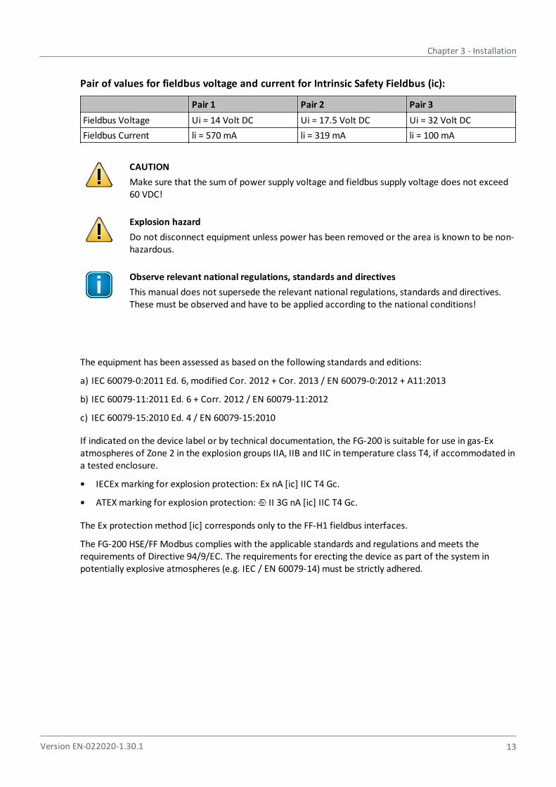
Pair of values for fieldbus voltage and current for Intrinsic Safety Fieldbus (ic):
Pair 1 Pair 2 Pair 3
Fieldbus Voltage Ui = 14 Volt DC Ui = 17.5 Volt DC Ui = 32 Volt DC
Fieldbus Current li = 570 mA li = 319 mA li = 100 mA
CAUTION
Make sure that the sum of power supply voltage and fieldbus supply voltage does not exceed60 VDC!
Explosion hazard
Do not disconnect equipment unless power has been removed or the area is known to be non-hazardous.
Observe relevant national regulations, standards and directives
This manual does not supersede the relevant national regulations, standards and directives.These must be observed and have to be applied according to the national conditions!
The equipment has been assessed as based on the following standards and editions:
a) IEC 60079-0:2011 Ed. 6, modified Cor. 2012 + Cor. 2013 / EN 60079-0:2012 + A11:2013
b) IEC 60079-11:2011 Ed. 6 + Corr. 2012 / EN 60079-11:2012
c) IEC 60079-15:2010 Ed. 4 / EN 60079-15:2010
If indicated on the device label or by technical documentation, the FG-200 is suitable for use in gas-Exatmospheres of Zone 2 in the explosion groups IIA, IIB and IIC in temperature class T4, if accommodated ina tested enclosure.
IECEx marking for explosion protection: Ex nA [ic] IIC T4 Gc.
ATEX marking for explosion protection: II 3G nA [ic] IIC T4 Gc.
The Ex protection method [ic] corresponds only to the FF-H1 fieldbus interfaces.
The FG-200 HSE/FF Modbus complies with the applicable standards and regulations and meets therequirements of Directive 94/9/EC. The requirements for erecting the device as part of the system inpotentially explosive atmospheres (e.g. IEC / EN 60079-14) must be strictly adhered.

FG-200 HSE/FF Modbus - User Manual
14 Version EN-022020-1.30.1
Certificates
ATEX The EC type examination number for ATEX is: BVS 15 ATEX E 063 XA copy of the certificate is available in section ATEX Type Examination Certificate .
IECEx The type examination number for IECEx is: IECEx BVS 15.0055XThe certificate can be downloaded from http://iecex.iec.ch
If indicated on the device label, the FG-200 is suitable for use in Class 1, Division 2, Groups A, B, C and Dhazardous or non-hazardous locations.
The device must be installed in a protective enclosure which meets the requirements for resistance toimpact and IP54 according to IEC 60529.
Marking for explosion protection: Class I Div.2 Groups A,B,C,D.
Certificate
cULus The cULus Certificate of Compliance number is: 20151215-E356500 A copy of the certificate is available in section UL Certificate of Compliance .
74
77
Chapter 3 - Installation
Version EN-022020-1.30.1 15
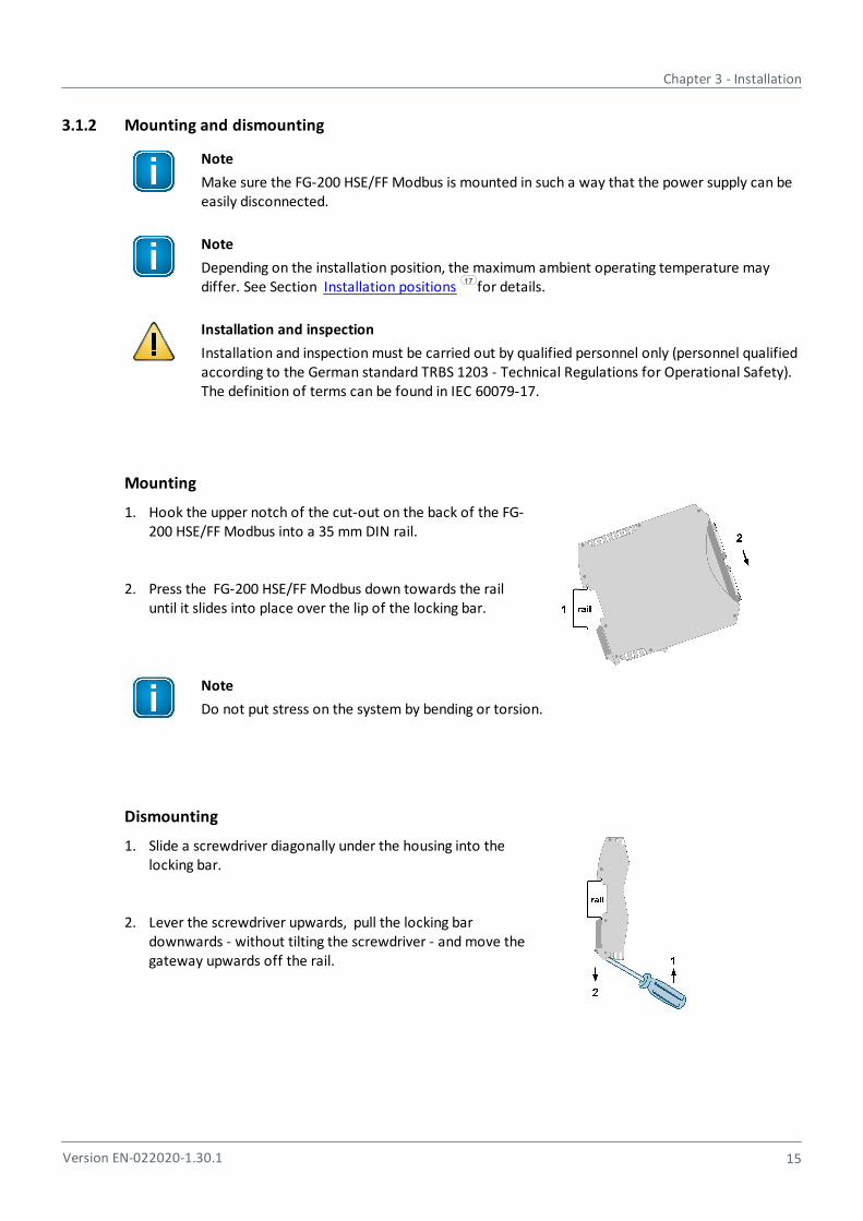
3.1.2 Mounting and dismounting
Note
Make sure the FG-200 HSE/FF Modbus is mounted in such a way that the power supply can beeasily disconnected.
Note
Depending on the installation position, the maximum ambient operating temperature maydiffer. See Section Installation positions for details.
Installation and inspection
Installation and inspection must be carried out by qualified personnel only (personnel qualifiedaccording to the German standard TRBS 1203 - Technical Regulations for Operational Safety).The definition of terms can be found in IEC 60079-17.
Mounting
1. Hook the upper notch of the cut-out on the back of the FG-200 HSE/FF Modbus into a 35 mm DIN rail.
2. Press the FG-200 HSE/FF Modbus down towards the railuntil it slides into place over the lip of the locking bar.
Note
Do not put stress on the system by bending or torsion.
Dismounting
1. Slide a screwdriver diagonally under the housing into thelocking bar.
2. Lever the screwdriver upwards, pull the locking bardownwards - without tilting the screwdriver - and move thegateway upwards off the rail.
17

FG-200 HSE/FF Modbus - User Manual
16 Version EN-022020-1.30.1
3.1.3 Connection diagram
The following connection diagram shows the physical interfaces of the FG-200.
3.1.4 Connecting the power supply
1. Connect the FG-200 to a 24 V DC power supply.
2. Use different or redundant power supplies for redundant FG-200s.
3. Turn on the power supply. The boot process takes approx. 50 seconds. For indication of properoperation of a FG-200 acting in non-redundant mode or as primary device in redundant mode refer to LED status indicators .
The supply voltage (18 VDC .... 32 VDC) is connected by a 3-pole terminal block. The power supply is
connected to the plug connector via flexible wires with a cross section of 0.75 to 1.5 mm². The ground
connection wire must have a cross section of 1.5 mm².
Pin Signal Description
1 GND Ground
2 Functional earth
3 L+ Positive supply voltage
CAUTION
The Functional Earth (FE) connection of the device has to be connected at low inductance withthe Protective Earth (PE) of the system.
Note
As indicated in the connection diagram, the power can be applied alternatively by a special DINrail connector (Rail Power Supply). For further information contact Softing IndustrialAutomation.
56

Chapter 3 - Installation
Version EN-022020-1.30.1 17
3.1.5 Installation positions
The FG-200 HSE/FF Modbus can be mounted horizontally and vertically. Depending on the installationposition, different ambient operating temperatures (Ta) are allowed.
Minimum distance
Provide a minimum distance of 50 mm to the air inlet and air outlet to ensure naturalconvection.
Rotated installation position
The maximum permissible ambient temperature values also apply to a 180° rotatedinstallation position.
Horizontal installation position
Maximum ambient temperatures for the FG-200 HSE/FF Modbus
Number of PAchannels used
Maximumfieldbus voltage
Minimum distance Maximum permissibleambient temperature Ta
4 32VDC 0 mm 55 °C
2 24VDC 0 mm 60 °C
4 32VDC 17.5 mm 65 °C
2 24VDC 17.5 mm 70 °C
FG-200 HSE/FF Modbus - User Manual
18 Version EN-022020-1.30.1
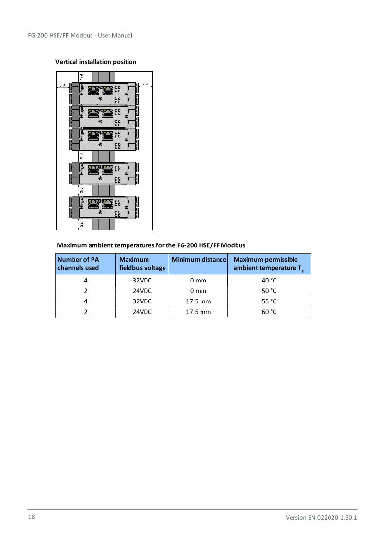
Vertical installation position
Maximum ambient temperatures for the FG-200 HSE/FF Modbus
Number of PAchannels used
Maximumfieldbus voltage
Minimum distance Maximum permissibleambient temperature Ta
4 32VDC 0 mm 40 °C
2 24VDC 0 mm 50 °C
4 32VDC 17.5 mm 55 °C
2 24VDC 17.5 mm 60 °C
Chapter 3 - Installation
Version EN-022020-1.30.1 19
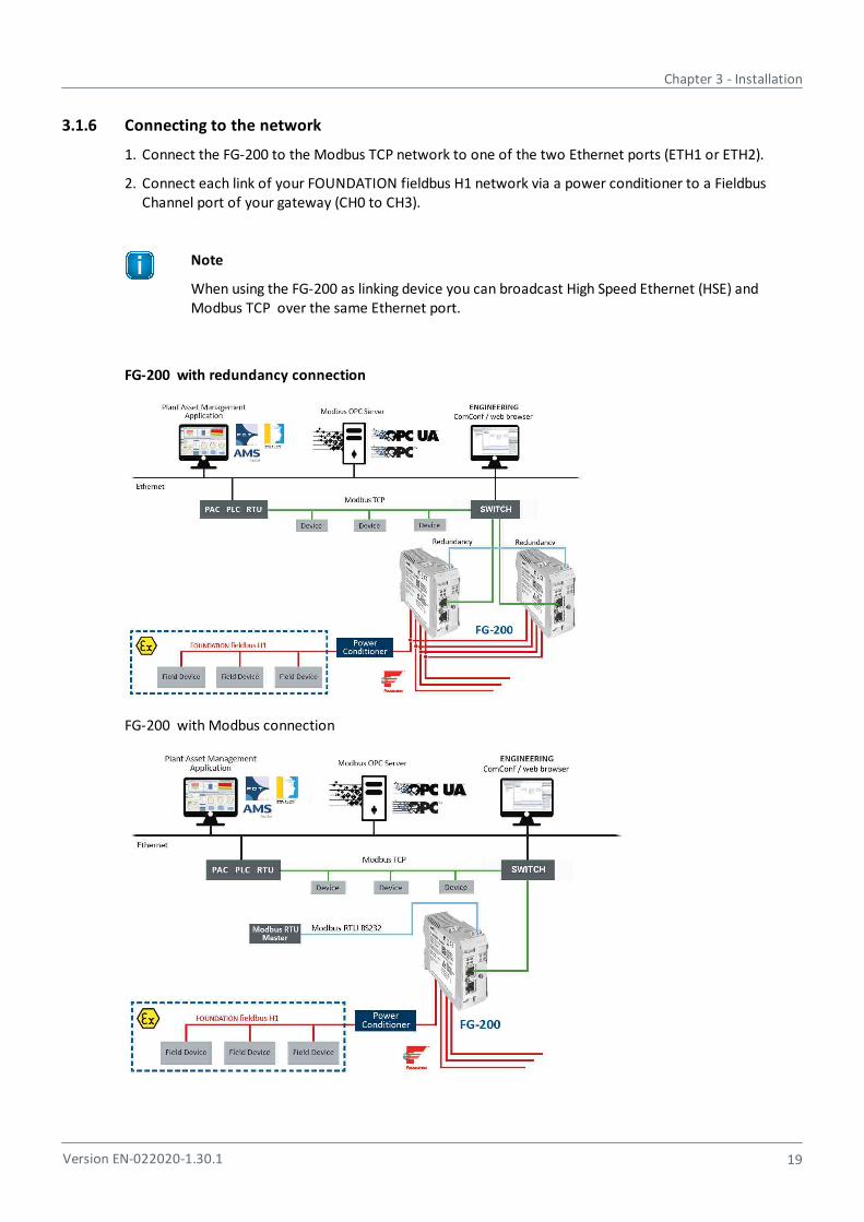
3.1.6 Connecting to the network
1. Connect the FG-200 to the Modbus TCP network to one of the two Ethernet ports (ETH1 or ETH2).
2. Connect each link of your FOUNDATION fieldbus H1 network via a power conditioner to a FieldbusChannel port of your gateway (CH0 to CH3).
Note
When using the FG-200 as linking device you can broadcast High Speed Ethernet (HSE) andModbus TCP over the same Ethernet port.
FG-200 with redundancy connection
FG-200 with Modbus connection

FG-200 HSE/FF Modbus - User Manual
20 Version EN-022020-1.30.1
Note
Your FG-200 cannot operate in both Modbus TCP and Modbus RTU mode at the same time.
Note
When you connect your FG-200 to a Modbus RTU Master you cannot operate the device inredundancy mode.
3.1.7 Modbus serial connection
When connecting the FG-200 via serial connection use the connector from your delivery with the followingpin assignment:
Pin No. Signal Connector symbol
6 RX +
5 TX S
4 GND -
Note
If you are working with two FG-200 in redundant mode, the serial connection cannot be used,refer to Use two FG-200s as a redundant set .
21

Chapter 3 - Installation
Version EN-022020-1.30.1 21
3.1.8 Using two FG-200
If you intend to use two FG-200 as a redundant set, connect the redundancy link interfaces (RDL) of bothFG-200 (primary and secondary) by a cable before you power up the devices. If the redundancy link is notinstalled before start-up, the FG-200 will operate in non-redundant mode.
Note
As the interface is not galvanically isolated make sure that there is no potential differencebetween the two connected devices.
The maximum cable length is 0.5 m according to EMC requirements. The pin assignment is:
Pin Signal Description
6 RX Receives data from redundant device
5 TX Transmits data to redundant device
4 GND Ground
NoteThe receive (RX) and transmit (TX) signals must be cross-linked.
Do not power up devices when serial link is missing
If the two FG-200 forming a redundant set are powered while the serial link is missing, both devices willbehave like independent, non-redundant Primary Devices. If they operated in redundant mode before andtherefore have identical configuration information, both will use the same H1 node addresses, which willcause problems on the H1 links. The ERR (error) LED will blink. In this case, remove the power, install theserial link and apply the power again.
Primary device vs. secondary device
When using a redundant set of two FG-200, the device which is powered first will operate as primarydevice. If both devices are powered at the same time, the one with the lower IP address will operate asprimary device.
Removing the power supply
Before you remove the power supply from the primary device make sure the secondary device isoperational. In a redundant set of FG-200, removing the power supply, the Ethernet cable or theredundancy link interface cable from the primary device causes a redundancy change-over. Before doingso, make sure that the secondary device is operational (and not still booting due to a prior change-over).Otherwise the system breaks down or the configuration information might get lost. Therefore wait at leastone minute between such checks.
FG-200 HSE/FF Modbus - User Manual
22 Version EN-022020-1.30.1
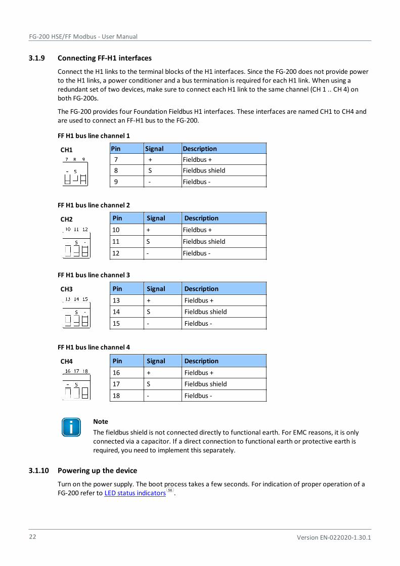
3.1.9 Connecting FF-H1 interfaces
Connect the H1 links to the terminal blocks of the H1 interfaces. Since the FG-200 does not provide powerto the H1 links, a power conditioner and a bus termination is required for each H1 link. When using aredundant set of two devices, make sure to connect each H1 link to the same channel (CH 1 .. CH 4) onboth FG-200s.
The FG-200 provides four Foundation Fieldbus H1 interfaces. These interfaces are named CH1 to CH4 andare used to connect an FF-H1 bus to the FG-200.
FF H1 bus line channel 1
CH1 Pin Signal Description
7 + Fieldbus +
8 S Fieldbus shield
9 - Fieldbus -
FF H1 bus line channel 2
CH2 Pin Signal Description
10 + Fieldbus +
11 S Fieldbus shield
12 - Fieldbus -
FF H1 bus line channel 3
CH3 Pin Signal Description
13 + Fieldbus +
14 S Fieldbus shield
15 - Fieldbus -
FF H1 bus line channel 4
CH4 Pin Signal Description
16 + Fieldbus +
17 S Fieldbus shield
18 - Fieldbus -
Note
The fieldbus shield is not connected directly to functional earth. For EMC reasons, it is onlyconnected via a capacitor. If a direct connection to functional earth or protective earth isrequired, you need to implement this separately.
3.1.10 Powering up the device
Turn on the power supply. The boot process takes a few seconds. For indication of proper operation of aFG-200 refer to LED status indicators .
56
Chapter 3 - Installation
Version EN-022020-1.30.1 23
3.1.11 Adding a second FG-200 to form a redundant set of FG-200
For adding a second FG-200 to an already commissioned FG-200 that is operating in the role "Primary, nobackup", the following steps are required:
1. Set the IP configuration (IP address and subnet mask) of the second FG-200 using the same IP subnet asthe primary device (see Configuration ).
2. Connect the H1 links to the terminal blocks of the H1 interfaces. Make sure to connect each H1 link tothe same channel (CH 1 .. CH 4) on both FG-200s.
3. Connect the second FG-200 to the Ethernet switch or hub.
4. Connect both RDL interfaces as mentioned in Section FG-200 redundancy.
5. Connect the second FG-200 to a 24 V DC power supply. Use different or redundant power supplies forredundant FG-200s.
6. After turning on the power supply the boot process takes approx. 50 seconds.
7. The second FG-200 will take over the configuration data from the primary device and will startoperation in the role "secondary". For more details about proper operation as a secondary device seealso the LED status indicators .
HintRefer to Section FG-200 redundancy for more information on the redundancy concept.
25
21
56
21

FG-200 HSE/FF Modbus - User Manual
24 Version EN-022020-1.30.1
3.2 Software installation
When you install a Softing product for the first time, you will be asked if you trust the publisher. Activatethe option Always trust software from Softing AG if you do not want to be asked in subsequentinstallations and select [Install] to start the installation.
1. Go to the FG200 product page to download the latest product software.
2. Start by downloading and installing the Search and Configure tool.
3. Follow the on-screen installation instructions.
4. Read the license agreement carefully.If you have questions, you can [Cancel] the installation at this point and contact us. Click [Print] if youwant to print the license agreement to a PDF or on a printer.
5. Select I accept the terms in the license agreement and click [Next].
6. Click [Install] to install the selected software application on your PC.While the installation is in progress, the status bar of the installation wizard shows the different stepsthat are being executed. If you want to abort the installation, click [Cancel] button. The installationwizard will undo all modifications that have been made to your computer up to this point. Otherwise,wait until the installation is completed.
7. Press [Finish] to complete the installation and exit the wizard.
NoteProceed with the installation of the other software packages.
Additional installationsDepending on your use case, install one of the following software packages:
Install the FDT frame application PACTware if you are using FDT technology. The PACTware package includes the communication DTM FFdtm.
Install FFdtm if you prefer using a different FDT frame application such as FieldCare, FieldMate orothers to allow using a CommDTM in another FDT frame application.
Install Communication Configuration Tool (comConf) for a complete network configuration.
Chapter 4 - Configuration
Version EN-022020-1.30.1 25
4 Configuration
The FG-200 is delivered with the pre-configured IP address 192.168.0.10.
Note
Before connecting the FG-200 to your LAN network, make sure that its IP address is not usedby another network station. To assign a new IP address to your PC, you must haveadministrator rights.
1. Open a browser (e.g. Internet Explorer or Firefox).
2. Enter the URL address 192.168.0.10 and press Enter.
3. Login with the following data:login name: administratorlogin password: fgadmin
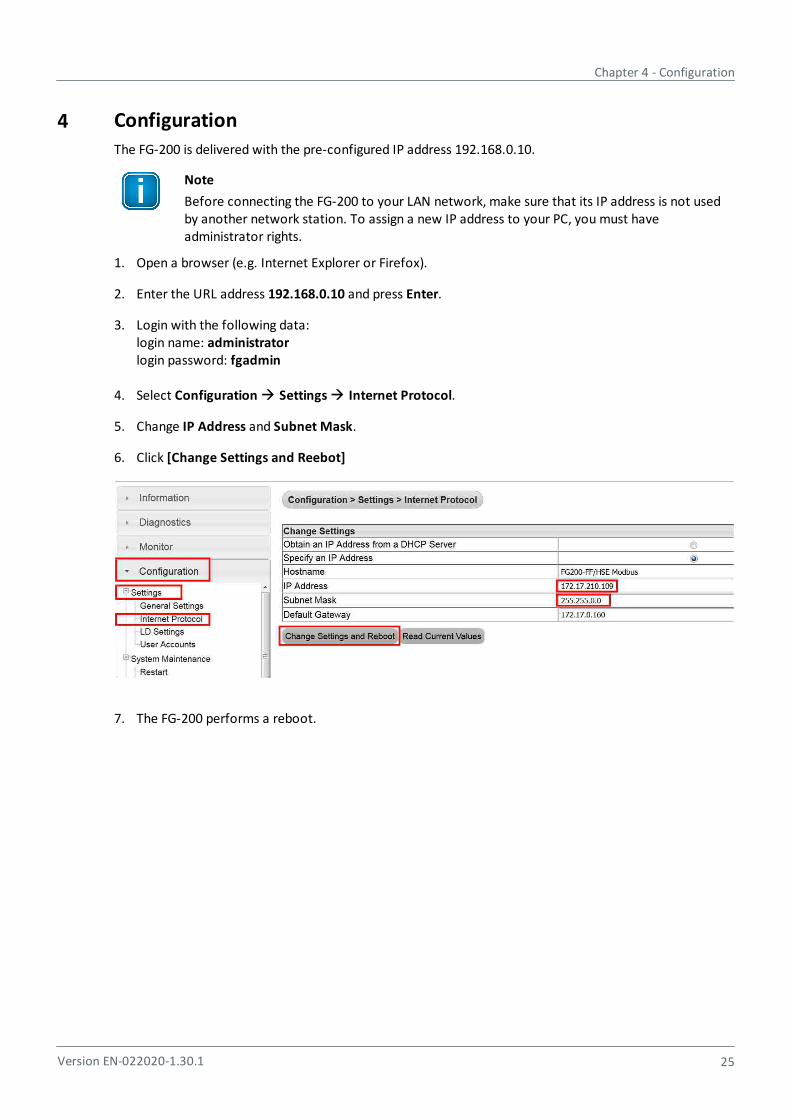
4. Select Configuration Settings Internet Protocol.
5. Change IP Address and Subnet Mask.
6. Click [Change Settings and Reebot]
7. The FG-200 performs a reboot.

FG-200 HSE/FF Modbus - User Manual
26 Version EN-022020-1.30.1
5 Working with the FG-200 HSE/FF Modbus
5.1 FG-200 acts as a Modbus / FF-H1 Gateway
Main purpose: PLC with Modbus interface accesses IO parameters of FF-H1 field devices
FG-200 supports access to IO parameters of FF-H1 field devices via client/server connections (CLT/SRVconnections) and via publisher/subscriber links (PUB/SUB links).
When accessing device IO parameters it is not possible to mix CLT/SRV connections and PUB/SUB links.For the selection of the communication mode see below.
5.1.1 FG-200 acts as link active scheduler
If FG-200 acts as a link active scheduler , no other FF host system is connected to the H1 segment.
For accessing field device parameters CLT/SRV connections as well as PUB/SUB links can be used. PUB/SUB links are the standard way for accessing IO parameters in FF installations. If you want to use PUB/SUBlinks, you have to configure them using the configuration tool comConf. For more information see the Configuration Communication Tool User Guide.
As there is no other FF host system you have to download the function block schedule into the fielddevices. You can generate the function block schedule and download it to the field devices by means ofcomConf.
Before you go online with the comConf update your general settings in the FG-200's web interface. Go to Configuration Settings General Settings:
If you have changed your settings click [Change Settings] to apply the new values. For more configurationdetails, see the Configuration Communication Tool User Guide.
5.1.2 FG-200 acts as visitor host
In this case the FG-200 is connected to an H1 segment that is controlled by another FF host system. Thelinks between the FF field devices and the FF host system are working. The FG-200 is not allowed to disturbthe operation by reconfiguring working communication paths.
The FG-200 is just allowed to use CLT/SRV connections for reading contained parameters and functionblock output parameters. The parameters to be read have to be configured in the Softing ConfigurationCommunication Tool (comConf). See the comConf User Guide for more details.
Important Note
If the FG-200 acts as a visitor host, no comConf project must be downloaded into the FG-200and the field devices.
61
60
60
61
Chapter 5 - Working with the FG-200 HSE/FF Modbus
Version EN-022020-1.30.1 27
Parameter settings
Make sure Enable automatic VCR Creation is activated.
Activate or deactivate Link Master Functionality depending on the following presumptions:
For this scenario we recommend configuring the Node Address within the range from 252 to 255 forthe FG-200. If you want prevent the FG-200 to take an active role in the H1 segments, deactivate LinkMaster Functionality. Usually this is not required if the H1 bus parameters used in the control systemare not too slow.
If Link Master Functionality is activated make sure that all activated H1 links of the FG-200 areconnected to H1 segments with an active host system interface. Otherwise the FG-200 would wait fora 6 minute period for activity on the H1 segments and would then disable the segments withoutactivity i.e. the segments without an active host interface.
5.1.3 Configuring the Modbus mapping table
The FG-200 supports the mapping of a set of function block parameters to Modbus registers. The set ofavailable parameters depends on the type of communication (PUB/SUB links or CLT/SRV connections)used for transferring IO data.
The FG-200 selects PUB/SUB links or CLT/SRV connections depending on the downloaded comConfproject.
Perform mapping on the web server application
Prerequisite: You have downloaded the comConf project.
1. Open the web browser and login.
2. Go to Configuration Fieldbus Blocks and click [Reload Live List].
3. Select Configuration Fieldbus Devices.
4. Load the .csv file with the Modbus mapping. Select Configuration Modbus Mapping Import/Export.Click [Import] and load the file generated by comConf.
Mapped values are now accessible in the configured Modbus registers and can be accessed by a Modbuscontrol.
FG-200 HSE/FF Modbus - User Manual
28 Version EN-022020-1.30.1
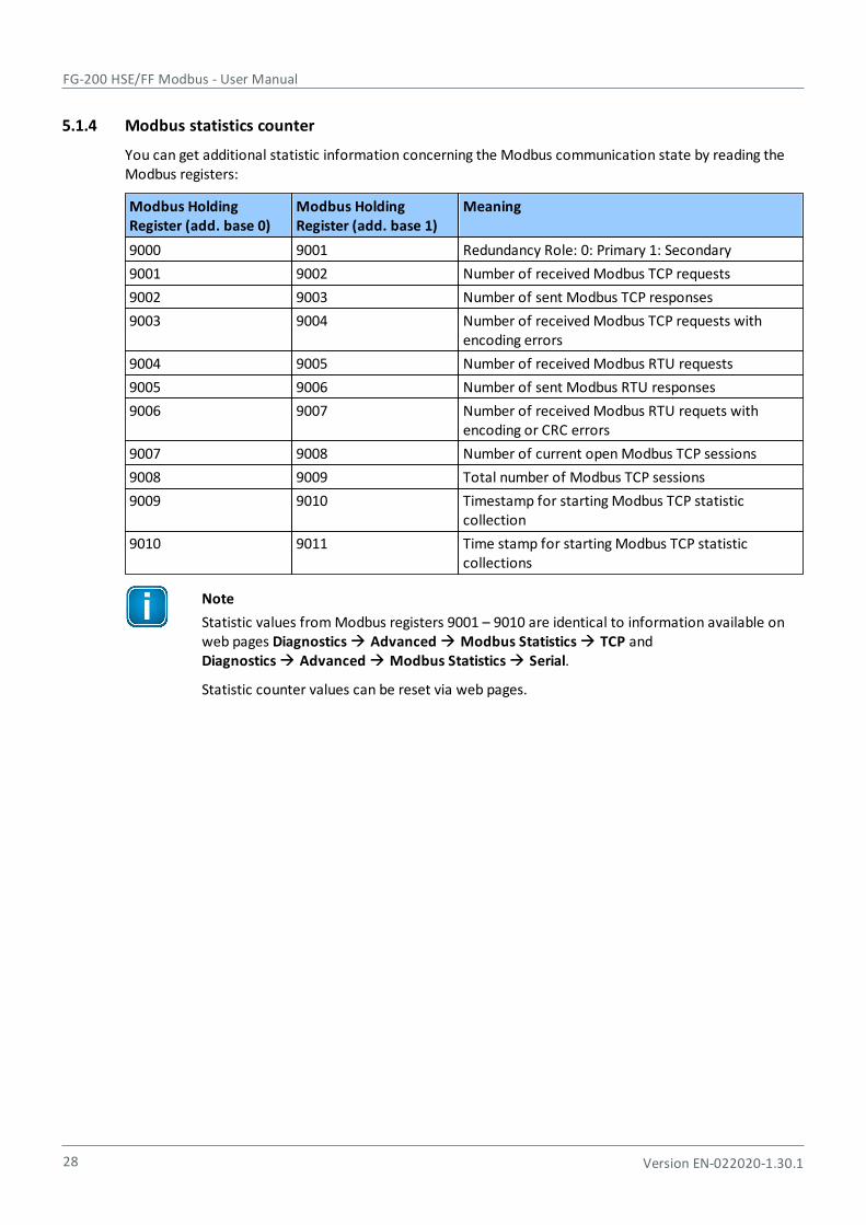
5.1.4 Modbus statistics counter
You can get additional statistic information concerning the Modbus communication state by reading theModbus registers:
Modbus HoldingRegister (add. base 0)
Modbus HoldingRegister (add. base 1)
Meaning
9000 9001 Redundancy Role: 0: Primary 1: Secondary
9001 9002 Number of received Modbus TCP requests
9002 9003 Number of sent Modbus TCP responses
9003 9004 Number of received Modbus TCP requests withencoding errors
9004 9005 Number of received Modbus RTU requests
9005 9006 Number of sent Modbus RTU responses
9006 9007 Number of received Modbus RTU requets withencoding or CRC errors
9007 9008 Number of current open Modbus TCP sessions
9008 9009 Total number of Modbus TCP sessions
9009 9010 Timestamp for starting Modbus TCP statisticcollection
9010 9011 Time stamp for starting Modbus TCP statisticcollections
Note
Statistic values from Modbus registers 9001 – 9010 are identical to information available onweb pages Diagnostics Advanced Modbus Statistics TCP and Diagnostics Advanced Modbus Statistics Serial.
Statistic counter values can be reset via web pages.
Chapter 5 - Working with the FG-200 HSE/FF Modbus
Version EN-022020-1.30.1 29
5.2 FG-200 acts as a FF-HSE/ FF-H1 gateway
5.2.1 FG-200 acts as an H1 interface used by Emerson AMS System
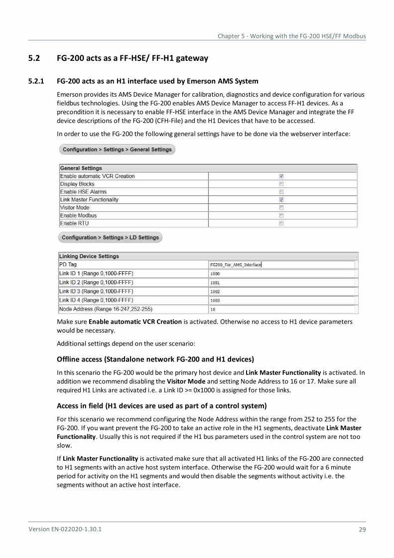
Emerson provides its AMS Device Manager for calibration, diagnostics and device configuration for variousfieldbus technologies. Using the FG-200 enables AMS Device Manager to access FF-H1 devices. As aprecondition it is necessary to enable FF-HSE interface in the AMS Device Manager and integrate the FFdevice descriptions of the FG-200 (CFH-File) and the H1 Devices that have to be accessed.
In order to use the FG-200 the following general settings have to be done via the webserver interface:
Make sure Enable automatic VCR Creation is activated. Otherwise no access to H1 device parameterswould be necessary.
Additional settings depend on the user scenario:
Offline access (Standalone network FG-200 and H1 devices)
In this scenario the FG-200 would be the primary host device and Link Master Functionality is activated. Inaddition we recommend disabling the Visitor Mode and setting Node Address to 16 or 17. Make sure allrequired H1 Links are activated i.e. a Link ID >= 0x1000 is assigned for those links.
Access in field (H1 devices are used as part of a control system)
For this scenario we recommend configuring the Node Address within the range from 252 to 255 for theFG-200. If you want prevent the FG-200 to take an active role in the H1 segments, deactivate Link MasterFunctionality. Usually this is not required if the H1 bus parameters used in the control system are not tooslow.
If Link Master Functionality is activated make sure that all activated H1 links of the FG-200 are connectedto H1 segments with an active host system interface. Otherwise the FG-200 would wait for a 6 minuteperiod for activity on the H1 segments and would then disable the segments without activity i.e. thesegments without an active host interface.

FG-200 HSE/FF Modbus - User Manual
30 Version EN-022020-1.30.1
H1 Device Alarms
AMS Device Manager supports monitoring a subset of H1 device alarms. To make use of this functionalityyou need to enable this feature in the AMS Device Manager and to configure the FG-200 and the attachedH1 devices accordingly. Note that within AMS Device Manager alarms are designated as "Alerts". Activatethis setting with Enable HSE Alarms in the General Settings web page of the FG-200.
We recommend activating Visitor Mode in the General settings web page. Thus you disable the alarmconfiguration of H1 devices. This would prevent an impact on an existing device configuration but couldlead to situations where it is not possible to receive alarms from some H1 devices. To display whichdevices are affected go to Configuration Fieldbus Device and search in column "Alarm configured"for the respective device.
AMS Device Manager is supporting standard Fieldbus Foundation alarm messaging using the UDP protocol,but it has an preconfigured UDP multicast address (239.255.0.33) and UDP port (45000) for the receptionof the alarm messages. This is used as default in the FG-200 but could be altered if a future AMS DeviceManager version would expect a different multicast address or UDP port by changing the settings in thefollowing web page.

Chapter 6 - Using the web interface
Version EN-022020-1.30.1 31
6 Using the web interface
After an IP connection between PC and FG-200 has been set up as described in Configuration , you mayaccess the FG-200 from your PC by means of a web browser that supports JavaScript (e.g. MicrosoftInternet Explorer).
The internal web server of the FG-200 offers the possibilities to configure the device (such as IP addresssettings or Modbus mapping), to get diagnostic information on the fieldbus or Modbus as well as tomonitor process values of the connected field devices.
6.1 Login to webserver
1. Start your web browser with the URL http://192.168.0.10. You are prompted to log in with username and password.
2. Enter administrator in the field Username.
3. Enter fgadmin in the Password field (default setting - refer also to Settings - User Accounts ).The start page is opened - in our example the Information page (refer to Homepage submenu) .Depending on the web browser you are using the information presentation may vary slightly:
The menu bar on the left side offers three main menus and several submenus:
Information menu
Diagnostics menu
Monitor menu
Configuration menu
Note
If you erase the FG-200 configuration, the password is reset to its default value.
25
39
46
32
33
35
36
FG-200 HSE/FF Modbus - User Manual
32 Version EN-022020-1.30.1
6.2 Information menu
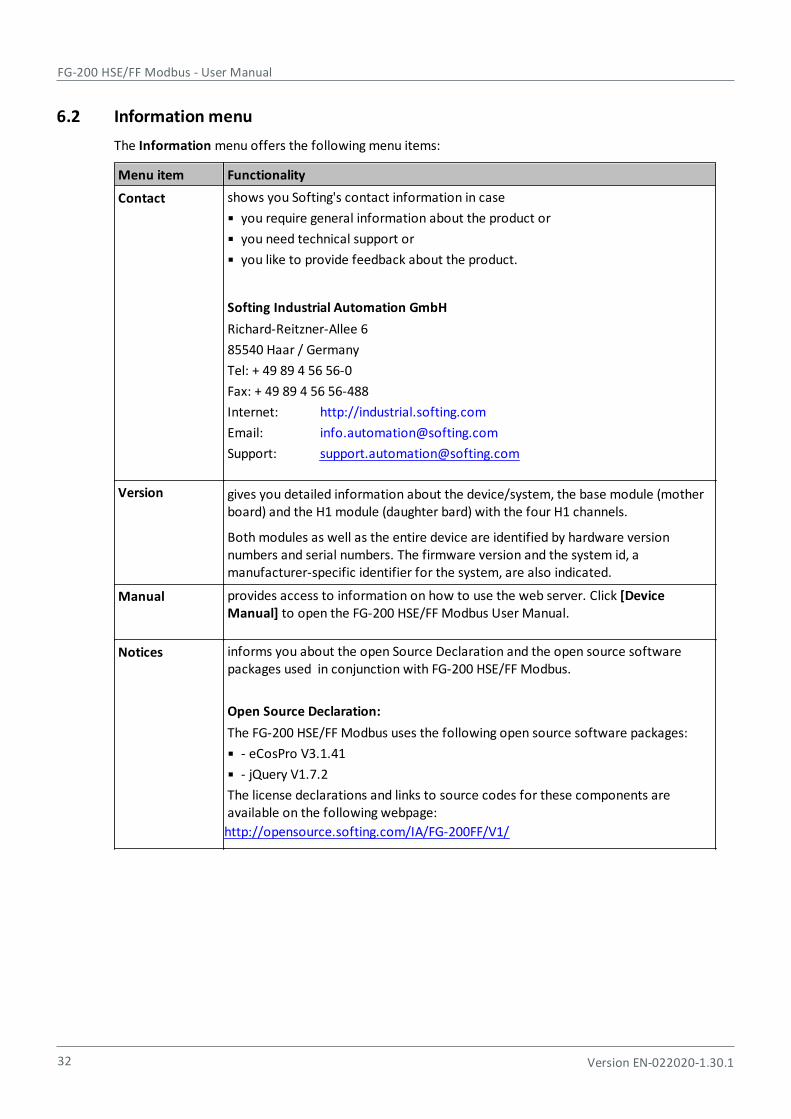
The Information menu offers the following menu items:
Menu item Functionality
Contact shows you Softing's contact information in case
you require general information about the product or
you need technical support or
you like to provide feedback about the product.
Softing Industrial Automation GmbH
Richard-Reitzner-Allee 6
85540 Haar / Germany
Tel: + 49 89 4 56 56-0
Fax: + 49 89 4 56 56-488
Internet: http://industrial.softing.com
Email: [email protected]
Support: [email protected]
Version gives you detailed information about the device/system, the base module (motherboard) and the H1 module (daughter bard) with the four H1 channels.
Both modules as well as the entire device are identified by hardware versionnumbers and serial numbers. The firmware version and the system id, amanufacturer-specific identifier for the system, are also indicated.
Manual provides access to information on how to use the web server. Click [DeviceManual] to open the FG-200 HSE/FF Modbus User Manual.
Notices informs you about the open Source Declaration and the open source softwarepackages used in conjunction with FG-200 HSE/FF Modbus.
Open Source Declaration:
The FG-200 HSE/FF Modbus uses the following open source software packages:
- eCosPro V3.1.41
- jQuery V1.7.2
The license declarations and links to source codes for these components areavailable on the following webpage:
http://opensource.softing.com/IA/FG-200FF/V1/
Chapter 6 - Using the web interface
Version EN-022020-1.30.1 33
6.3 Diagnostics menu
Click Diagnostics to open the following menus:
System
Internet Protocol
Fieldbus
Advanced
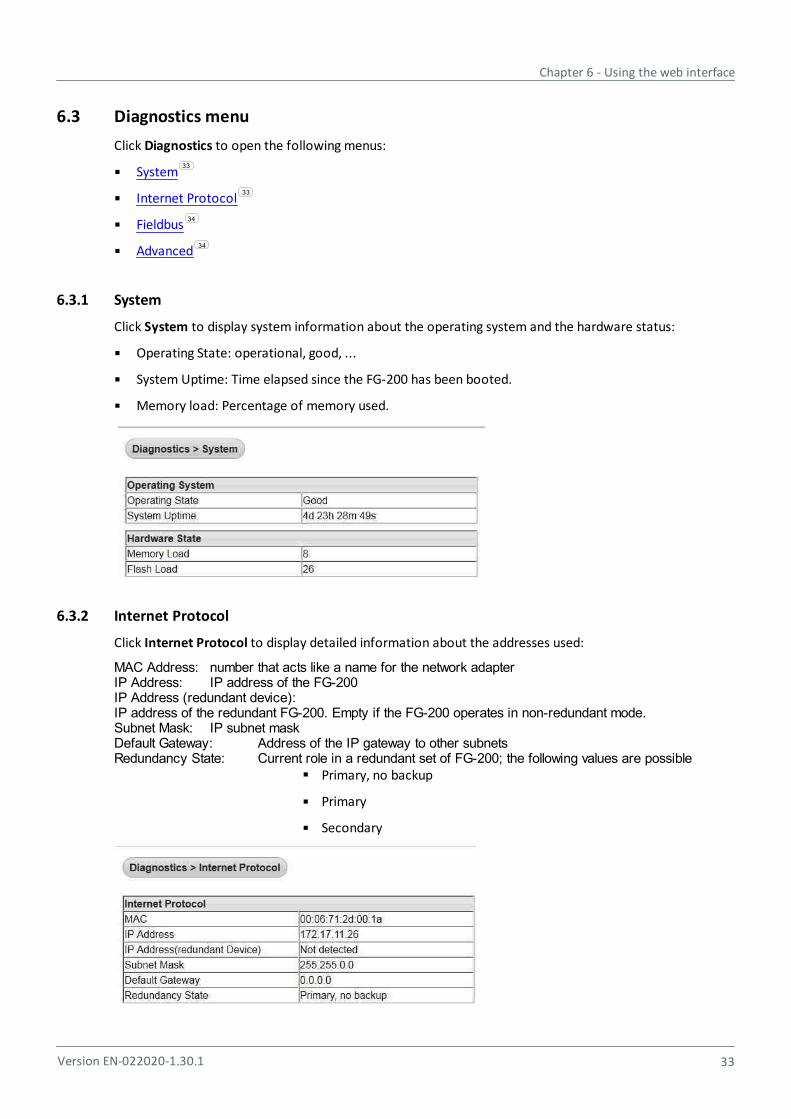
6.3.1 System
Click System to display system information about the operating system and the hardware status:
Operating State: operational, good, ...
System Uptime: Time elapsed since the FG-200 has been booted.
Memory load: Percentage of memory used.
6.3.2 Internet Protocol
Click Internet Protocol to display detailed information about the addresses used:
MAC Address: number that acts like a name for the network adapterIP Address: IP address of the FG-200IP Address (redundant device):IP address of the redundant FG-200. Empty if the FG-200 operates in non-redundant mode.Subnet Mask: IP subnet maskDefault Gateway: Address of the IP gateway to other subnetsRedundancy State: Current role in a redundant set of FG-200; the following values are possible
Primary, no backup
Primary
Secondary
33
33
34
34
FG-200 HSE/FF Modbus - User Manual
34 Version EN-022020-1.30.1
6.3.3 Fieldbus
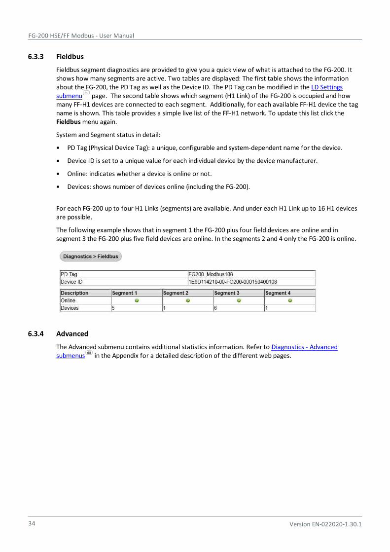
Fieldbus segment diagnostics are provided to give you a quick view of what is attached to the FG-200. Itshows how many segments are active. Two tables are displayed: The first table shows the informationabout the FG-200, the PD Tag as well as the Device ID. The PD Tag can be modified in the LD Settingssubmenu page. The second table shows which segment (H1 Link) of the FG-200 is occupied and howmany FF-H1 devices are connected to each segment. Additionally, for each available FF-H1 device the tagname is shown. This table provides a simple live list of the FF-H1 network. To update this list click the Fieldbus menu again.
System and Segment status in detail:
PD Tag (Physical Device Tag): a unique, configurable and system-dependent name for the device.
Device ID is set to a unique value for each individual device by the device manufacturer.
Online: indicates whether a device is online or not.
Devices: shows number of devices online (including the FG-200).
For each FG-200 up to four H1 Links (segments) are available. And under each H1 Link up to 16 H1 devices are possible.
The following example shows that in segment 1 the FG-200 plus four field devices are online and insegment 3 the FG-200 plus five field devices are online. In the segments 2 and 4 only the FG-200 is online.
6.3.4 Advanced
The Advanced submenu contains additional statistics information. Refer to Diagnostics - Advancedsubmenus in the Appendix for a detailed description of the different web pages.
39
68
Chapter 6 - Using the web interface
Version EN-022020-1.30.1 35
6.4 Monitor menu
The Monitor menu offers the following menu items:
Point Pages submenu
Point Data submenu
6.4.1 Point Pages submenu
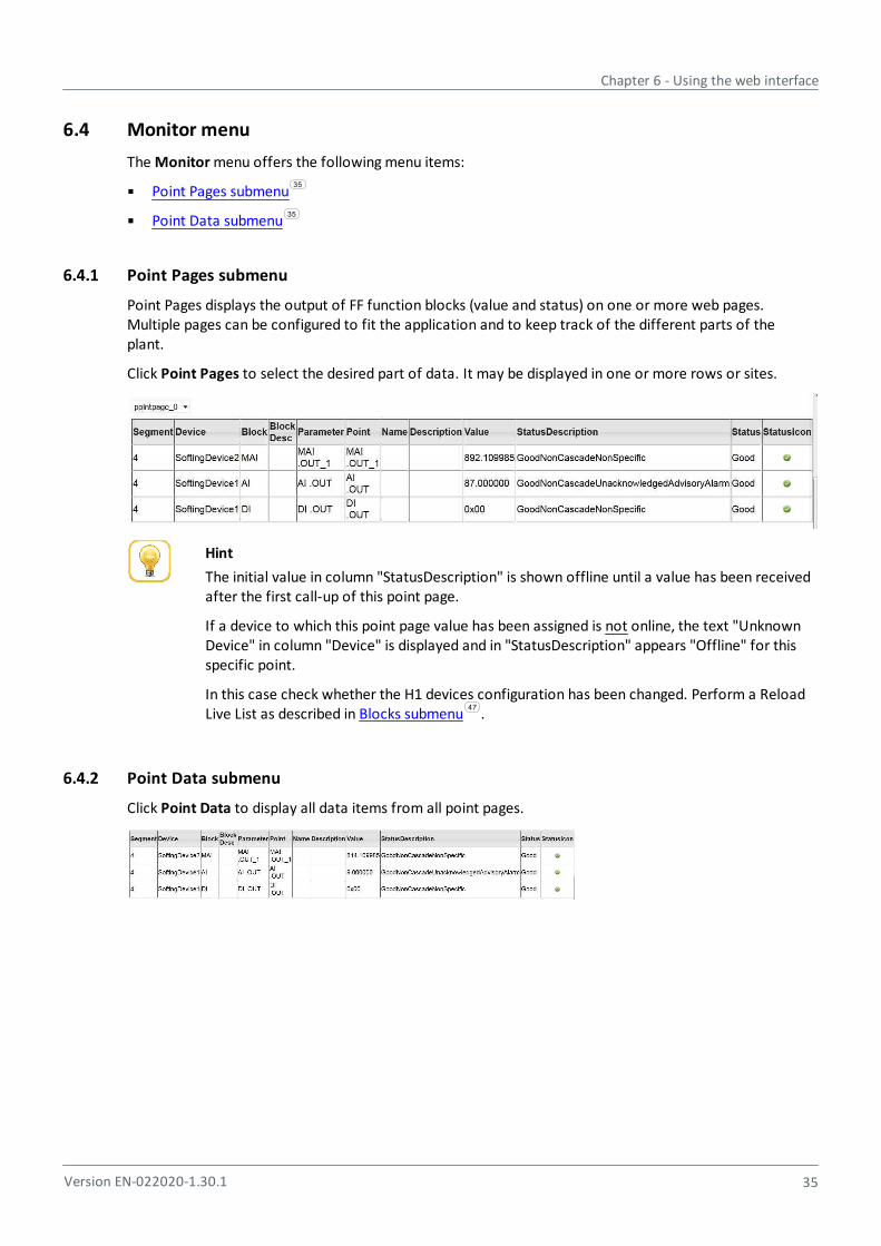
Point Pages displays the output of FF function blocks (value and status) on one or more web pages.Multiple pages can be configured to fit the application and to keep track of the different parts of theplant.
Click Point Pages to select the desired part of data. It may be displayed in one or more rows or sites.
Hint
The initial value in column "StatusDescription" is shown offline until a value has been receivedafter the first call-up of this point page.
If a device to which this point page value has been assigned is not online, the text "UnknownDevice" in column "Device" is displayed and in "StatusDescription" appears "Offline" for thisspecific point.
In this case check whether the H1 devices configuration has been changed. Perform a ReloadLive List as described in Blocks submenu .
6.4.2 Point Data submenu
Click Point Data to display all data items from all point pages.
35
35
47
FG-200 HSE/FF Modbus - User Manual
36 Version EN-022020-1.30.1
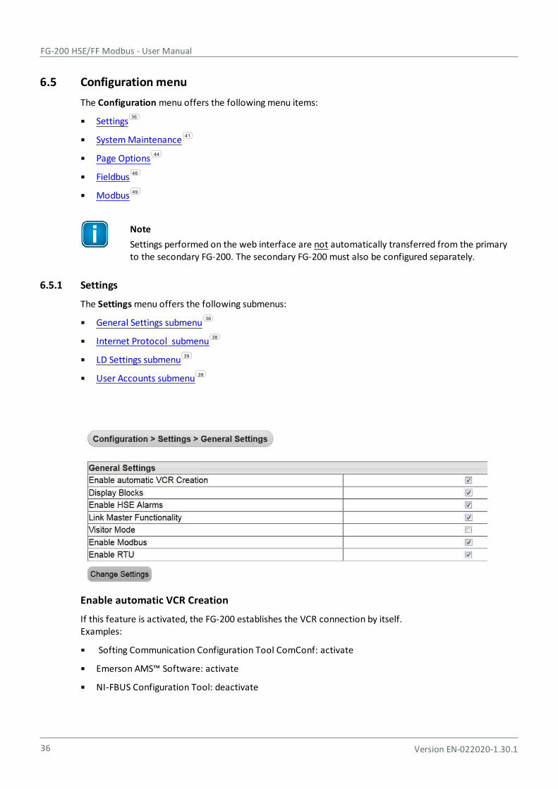
6.5 Configuration menu
The Configuration menu offers the following menu items:
Settings
System Maintenance
Page Options
Fieldbus
Modbus
Note
Settings performed on the web interface are not automatically transferred from the primaryto the secondary FG-200. The secondary FG-200 must also be configured separately.
6.5.1 Settings
The Settings menu offers the following submenus:
General Settings submenu
Internet Protocol submenu
LD Settings submenu
User Accounts submenu
Enable automatic VCR Creation
If this feature is activated, the FG-200 establishes the VCR connection by itself. Examples:
Softing Communication Configuration Tool ComConf: activate
Emerson AMS™ Software: activate
NI-FBUS Configuration Tool: deactivate
36
41
44
46
49
36
38
39
39

Chapter 6 - Using the web interface
Version EN-022020-1.30.1 37
Note
The feature Enable automatic VCR Creation has to be activated when the tool comConfis to be used for the Foundation fieldbus configuration.
Display Blocks
This feature enables or disables the point page functionality.
Hint
The use of the point pages creates a lot of traffic of the FF-H1 network. If you do not use thisMonitor feature then you can save more H1 bandwidth and faster reaction time over Modbus.
Enable HSE Alarms
The FG-200 is able to use the already configured alarm VCRs in the FF-H1 devices or can established newones. Or it will configure the FF-H1 devices accordingly. The behavior depends whether the Visitor Mode isenabled or not.
Link Master Functionality
In case of visitor mode it can make sense to disable the Link Master functionality. If no Link Master isavailable on a segment connected to an activated H1 Link of the FG-200, a timeout will occur after 6minutes to indicate this. The FG-200 will not be visible in the HSE live list during this period. To avoid thisassure that a Link Master is present for all activated H1 Links or deactivate H1 Links of the FG-200.
Visitor Mode
When the FG-200 is in visitor mode it can be connected to a running FF-H1 network with the FF-Hostsystem without affecting the established communication.
Enable Modbus
This button enables or disables Modbus TCP.
Enable RTU (Modbus RTU)
Modbus RTU runs over the same serial interface (RS232) which is necessary to establish an applicationwith HSE device redundancy. To use redundancy together with Modbus TCP the feature "Modbus RTU" hasto be disabled.
Note
If you are using Modbus TCP, activate the option Enable Modbus only.
If you are using Modbus RTU, activate both options Enable Modbus and Enable RTU.
The button [Change Settings] allows you to update the settings. To see the updated values click GeneralSettings again.
35

FG-200 HSE/FF Modbus - User Manual
38 Version EN-022020-1.30.1
The FG-200 is delivered in a default configuration. To change the default internet protocol settings toassigned values of the chosen subnet in which the installation is running, select Configuration, thenInternet Protocol.
A table enabling you to change settings appears. You can click
Obtain an IP address from a DHCP server to obtain a random address chosen from the DHCP server.
To find out the IP address of the FG-200 you can use the function Network Livelist in the comConftool. The tool is available on your delivery CD-ROM or can be downloaded from the Softing downloadarea.
or
Specify an IP Address to activate the fields in the table below:
Host name: configurable name for the host
IP Address: must be compatible with the subnet you choose for the PC setting, must be present inany case.
Subnet mask: default with 255.255.0.0, no change needed, must be present in any case.
Default Gateway: It is not necessary to configure a Default Gateway if the host and FG-200 sharethe same network.
[Change Settings and Reboot]
When you click this button, the web site shuts down and the system reboots. The input values are checkedfor consistency. In case of problems the following error may be displayed: Failure: Wrong IP Settings.
The FG-200 reboots after a few seconds and the new values are accepted.
If you change the IP address of the FG-200, the IP connection between PC and FG-200 are lost. You have touse the new IP address to re-establish web access to the FG-200.
If all parameters are correct, the new values are accepted and displayed.
[Read Current Values]
If you changed some of the parameters and you are not sure of your changes, click the button [ReadCurrent Values]. Input fields which are already filled are shown again.

Chapter 6 - Using the web interface
Version EN-022020-1.30.1 39
The LD Settings submenu allows to change
the PD-Tag of the FG-200
the Link ID as well as
the Node Address of the H1 links.
Each FG-200 uses a default PD tag that includes the serial number. The default PD Tag is also used if theconfiguration is erased via the web server interface or during firmware download.
This menu allows you to change and confirm account passwords depending on the role. Due to the tasks auser executes in this web site there are several graduations for admission control. The following standardlogins and passwords are available.
Role Login name Password
Administrator administrator fgadmin
Service or maintenanceengineer
maintenance keepitgoing
User or operator operator runit
Executive executive showme
These passwords can be configured with administrator rights in the following window:
Enter the password into the corresponding field(s), confirm your entry and click [Change Password] toconfirm the modified password(s).
FG-200 HSE/FF Modbus - User Manual
40 Version EN-022020-1.30.1
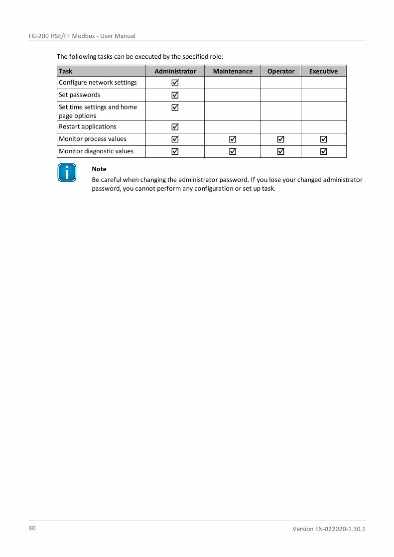
The following tasks can be executed by the specified role:
Task Administrator Maintenance Operator Executive
Configure network settings
Set passwords
Set time settings and homepage options
Restart applications
Monitor process values
Monitor diagnostic values
Note
Be careful when changing the administrator password. If you lose your changed administratorpassword, you cannot perform any configuration or set up task.
Chapter 6 - Using the web interface
Version EN-022020-1.30.1 41
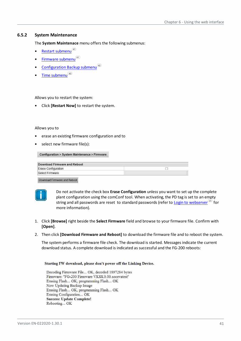
6.5.2 System Maintenance
The System Maintenace menu offers the following submenus:
Restart submenu
Firmware submenu
Configuration Backup submenu
Time submenu
Allows you to restart the system:
Click [Restart Now] to restart the system.
Allows you to
erase an existing firmware configuration and to
select new firmware file(s):
Do not activate the check box Erase Configuration unless you want to set up the completeplant configuration using the comConf tool. When activating, the PD tag is set to an emptystring and all passwords are reset to standard passwords (refer to Login to webserver formore information).
1. Click [Browse] right beside the Select Firmware field and browse to your firmware file. Confirm with[Open].
2. Then click [Download Firmware and Reboot] to download the firmware file and to reboot the system.
The system performs a firmware file check. The download is started. Messages indicate the currentdownload status. A complete download is indicated as successful and the FG-200 reboots:
41
41
42
43
31

FG-200 HSE/FF Modbus - User Manual
42 Version EN-022020-1.30.1
Note
Do not access the web server of the FG-200 before the "Success" message is displayed in thebrowser window. If you do so, you will have to clear the cache of your web browser after theboot process has finished, and then re-establish a connection to the web server of the FG-200.
The end of the boot process is indicated by a continuously lit RUN LED for a FG-200 acting in non-redundant mode or for a primary device in redundant mode. For a secondary device it is indicated by aflashing (1 Hz) RUN LED.
Allows you to
restore a selected system configuration,
save a selected configuration or to
erase the current configuration:
Restore Configuration
To restore a previously saved configuration click [Browse], select the desired configuration file andconfirm with [Open].
Save Configuration
1. To save your current configuration, click [Save Configuration]. An additional window is opened askingyou to save the file.
2. Click Save file and confirm with [OK]. The configuration file is saved to your standard downloaddirectory.
Erase Configuration
To erase an existing configuration and to reset the FG-200 back to factory default settings click [EraseConfiguration]. This action causes
the deletion of the current configuration (whereby the IP configuration is not changed),
passwords to be deleted and to be reset to their default value.
Important Note
When clicking [Erase Configuration] the configuration is immediately deleted.

Chapter 6 - Using the web interface
Version EN-022020-1.30.1 43
Allows you to
synchronize date and time between PC and device(s) or
set a specific date and time for your device:
Note
If an SNTP server is configured, you cannot modify date and time due to automatic timesynchronization.
Current Time displays
current time on your PC,
time on the Softing FG-200 and
difference between the current PC time and the time on the FG-200.
Set Time allows you to
synchronize the current PC time and the time of the FG-200. Activate Set with PC and then click [SetTime]. The synchronized time will appear in the table.If the FG-200 is connected to a network and if you want to use this feature, you can select atimeserver at your facility or one near you geographically to ensure accurate time adjustments. Thedevice will function properly with this feature disabled but data time stamps are less accurate and timeupdates must be entered for each FG-200
or
set the time manually. To do so, activate Manual Entry, then click into the corresponding field Dateand Time and enter the desired values. Confirm your changes by clicking [Set Time]. Your entries arethen activated.
FG-200 HSE/FF Modbus - User Manual
44 Version EN-022020-1.30.1
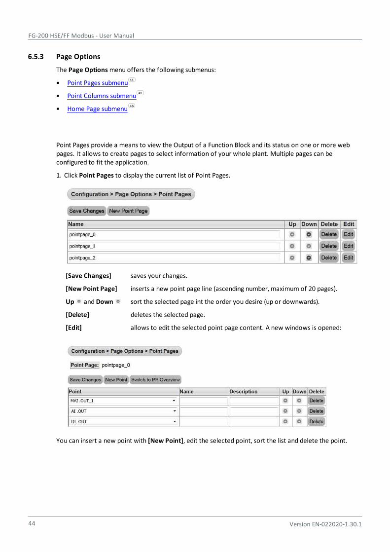
6.5.3 Page Options
The Page Options menu offers the following submenus:
Point Pages submenu
Point Columns submenu
Home Page submenu
Point Pages provide a means to view the Output of a Function Block and its status on one or more webpages. It allows to create pages to select information of your whole plant. Multiple pages can beconfigured to fit the application.
1. Click Point Pages to display the current list of Point Pages.
[Save Changes] saves your changes.
[New Point Page] inserts a new point page line (ascending number, maximum of 20 pages).
Up and Down sort the selected page int the order you desire (up or downwards).
[Delete] deletes the selected page.
[Edit] allows to edit the selected point page content. A new windows is opened:
You can insert a new point with [New Point], edit the selected point, sort the list and delete the point.
44
45
46
Chapter 6 - Using the web interface
Version EN-022020-1.30.1 45
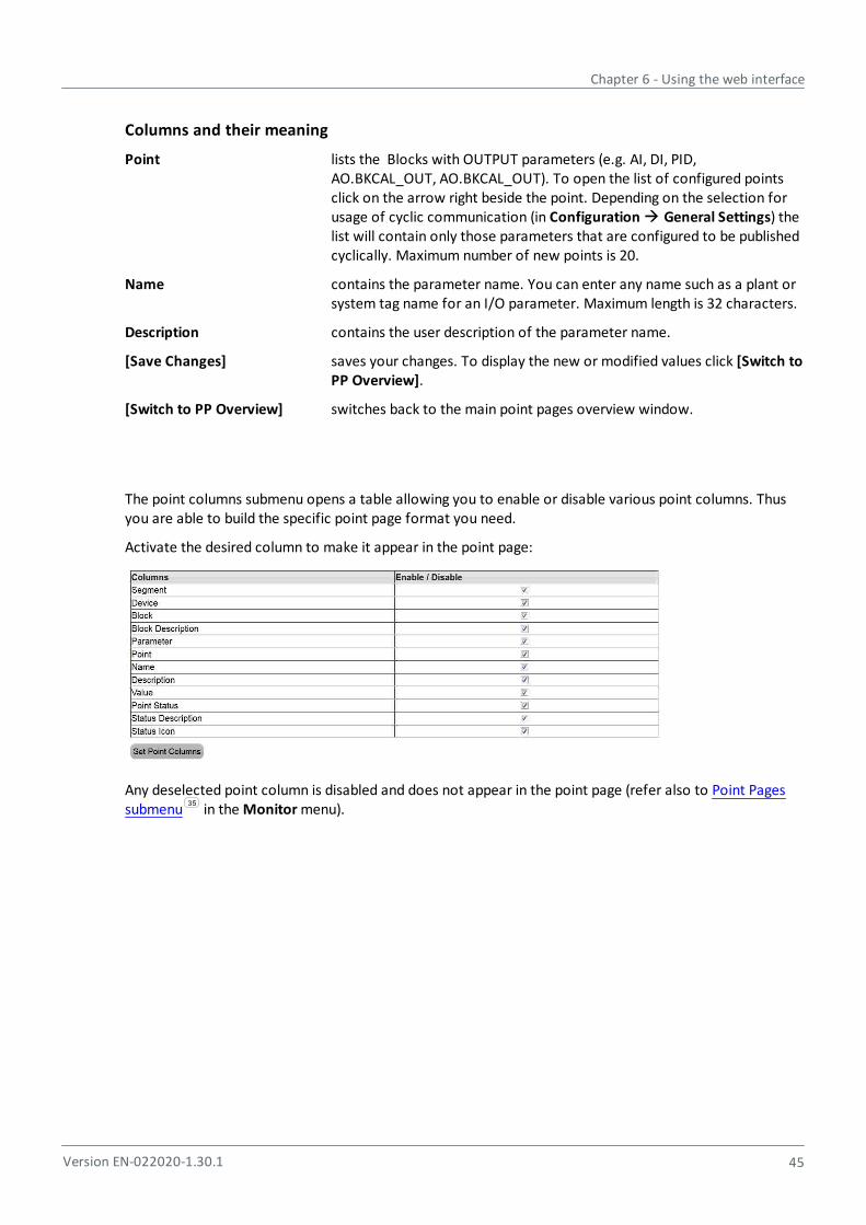
Columns and their meaning
Point lists the Blocks with OUTPUT parameters (e.g. AI, DI, PID,AO.BKCAL_OUT, AO.BKCAL_OUT). To open the list of configured pointsclick on the arrow right beside the point. Depending on the selection forusage of cyclic communication (in Configuration General Settings) thelist will contain only those parameters that are configured to be publishedcyclically. Maximum number of new points is 20.
Name contains the parameter name. You can enter any name such as a plant orsystem tag name for an I/O parameter. Maximum length is 32 characters.
Description contains the user description of the parameter name.
[Save Changes] saves your changes. To display the new or modified values click [Switch toPP Overview].
[Switch to PP Overview] switches back to the main point pages overview window.
The point columns submenu opens a table allowing you to enable or disable various point columns. Thusyou are able to build the specific point page format you need.
Activate the desired column to make it appear in the point page:
Any deselected point column is disabled and does not appear in the point page (refer also to Point Pagessubmenu in the Monitor menu).
35
FG-200 HSE/FF Modbus - User Manual
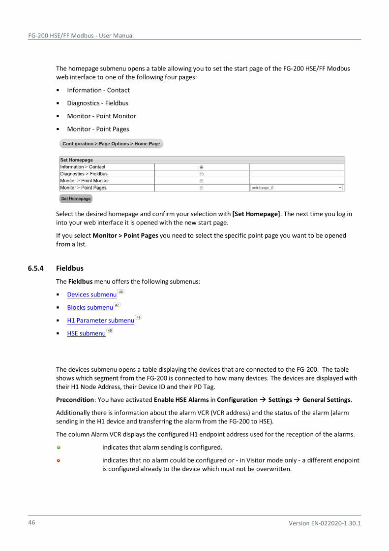
46 Version EN-022020-1.30.1
The homepage submenu opens a table allowing you to set the start page of the FG-200 HSE/FF Modbusweb interface to one of the following four pages:
Information - Contact
Diagnostics - Fieldbus
Monitor - Point Monitor
Monitor - Point Pages
Select the desired homepage and confirm your selection with [Set Homepage]. The next time you log ininto your web interface it is opened with the new start page.
If you select Monitor > Point Pages you need to select the specific point page you want to be openedfrom a list.
6.5.4 Fieldbus
The Fieldbus menu offers the following submenus:
Devices submenu
Blocks submenu
H1 Parameter submenu
HSE submenu
The devices submenu opens a table displaying the devices that are connected to the FG-200. The tableshows which segment from the FG-200 is connected to how many devices. The devices are displayed withtheir H1 Node Address, their Device ID and their PD Tag.
Precondition: You have activated Enable HSE Alarms in Configuration Settings General Settings.
Additionally there is information about the alarm VCR (VCR address) and the status of the alarm (alarmsending in the H1 device and transferring the alarm from the FG-200 to HSE).
The column Alarm VCR displays the configured H1 endpoint address used for the reception of the alarms.
indicates that alarm sending is configured.
indicates that no alarm could be configured or - in Visitor mode only - a different endpointis configured already to the device which must not be overwritten.
46
47
48
48
Chapter 6 - Using the web interface
Version EN-022020-1.30.1 47
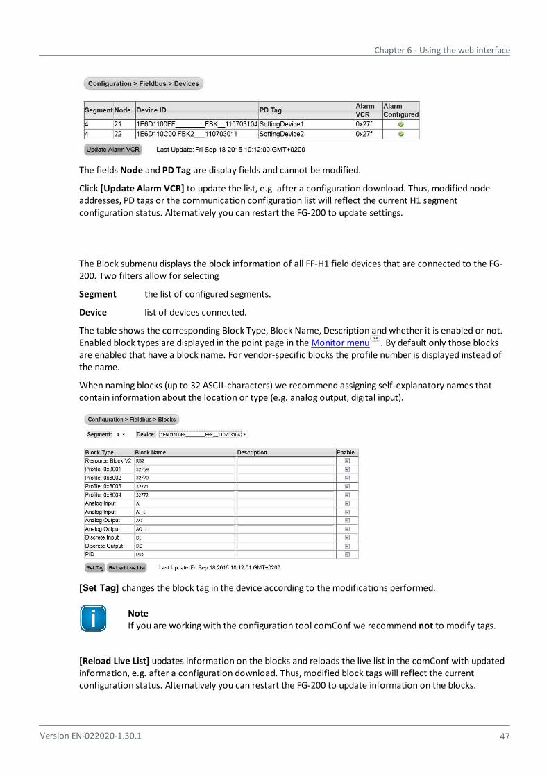
The fields Node and PD Tag are display fields and cannot be modified.
Click [Update Alarm VCR] to update the list, e.g. after a configuration download. Thus, modified nodeaddresses, PD tags or the communication configuration list will reflect the current H1 segmentconfiguration status. Alternatively you can restart the FG-200 to update settings.
The Block submenu displays the block information of all FF-H1 field devices that are connected to the FG-200. Two filters allow for selecting
Segment the list of configured segments.
Device list of devices connected.
The table shows the corresponding Block Type, Block Name, Description and whether it is enabled or not.Enabled block types are displayed in the point page in the Monitor menu . By default only those blocksare enabled that have a block name. For vendor-specific blocks the profile number is displayed instead ofthe name.
When naming blocks (up to 32 ASCII-characters) we recommend assigning self-explanatory names thatcontain information about the location or type (e.g. analog output, digital input).
[Set Tag] changes the block tag in the device according to the modifications performed.
NoteIf you are working with the configuration tool comConf we recommend not to modify tags.
[Reload Live List] updates information on the blocks and reloads the live list in the comConf with updatedinformation, e.g. after a configuration download. Thus, modified block tags will reflect the currentconfiguration status. Alternatively you can restart the FG-200 to update information on the blocks.
35
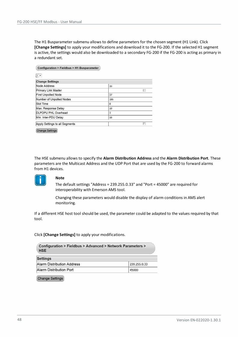
FG-200 HSE/FF Modbus - User Manual
48 Version EN-022020-1.30.1
The H1 Busparameter submenu allows to define parameters for the chosen segment (H1 Link). Click [Change Settings] to apply your modifications and download it to the FG-200. If the selected H1 segmentis active, the settings would also be downloaded to a secondary FG-200 if the FG-200 is acting as primary ina redundant set.
The HSE submenu allows to specify the Alarm Distribution Address and the Alarm Distribution Port. Theseparameters are the Multicast Address and the UDP Port that are used by the FG-200 to forward alarmsfrom H1 devices.
Note
The default settings "Address = 239.255.0.33" and "Port = 45000" are required forinteroperability with Emerson AMS tool.
Changing these parameters would disable the display of alarm conditions in AMS alertmonitoring.
If a different HSE host tool should be used, the parameter could be adapted to the values required by thattool.
Click [Change Settings] to apply your modifications.
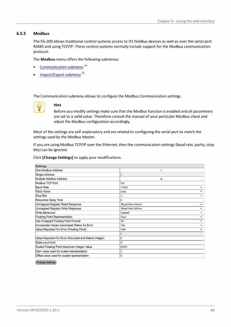
Chapter 6 - Using the web interface
Version EN-022020-1.30.1 49
6.5.5 Modbus
The FG-200 allows traditional control systems access to H1 fieldbus devices as well as over the serial portRS485 and using TCP/IP. These control systems normally include support for the Modbus communicationprotocol.
The Modbus menu offers the following submenus:
Communication submenu
Import/Export submenu
The Communication submenu allows to configure the Modbus Communication settings.
Hint
Before you modify settings make sure that the Modbus function is enabled and all parametersare set to a valid value. Therefore consult the manual of your particular Modbus client andadjust the Modbus configuration accordingly.
Most of the settings are self-explanatory and are related to configuring the serial port to match thesettings used by the Modbus Master.
If you are using Modbus TCP/IP over the Ethernet, then the communication settings (baud rate, parity, stopbits) can be ignored.
Click [Change Settings] to apply your modifications.
49
50

FG-200 HSE/FF Modbus - User Manual
50 Version EN-022020-1.30.1
In this submenu you can import a Modbus mapping created by comConf.
Note
The Modbus mapping table cannot be specified by the user any longer. Current you import a Modbus mapping created by the Softing ComConf.
[Export] Saves the imported Modbus Mapping table.
[Import] Imports an existing Modbus Mapping table in csv format.
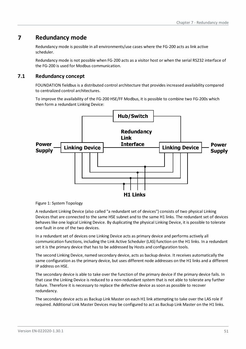
Chapter 7 - Redundancy mode
Version EN-022020-1.30.1 51
7 Redundancy mode
Redundancy mode is possible in all environments/use cases where the FG-200 acts as link activescheduler.
Redundancy mode is not possible when FG-200 acts as a visitor host or when the serial RS232 interface ofthe FG-200 is used for Modbus communication.
7.1 Redundancy concept
FOUNDATION fieldbus is a distributed control architecture that provides increased availability comparedto centralized control architectures.
To improve the availability of the FG-200 HSE/FF Modbus, it is possible to combine two FG-200s whichthen form a redundant Linking Device:
Figure 1: System Topology
A redundant Linking Device (also called "a redundant set of devices") consists of two physical LinkingDevices that are connected to the same HSE subnet and to the same H1 links. The redundant set of devicesbehaves like one logical Linking Device. By duplicating the physical Linking Device, it is possible to tolerateone fault in one of the two devices.
In a redundant set of devices one Linking Device acts as primary device and performs actively allcommunication functions, including the Link Active Scheduler (LAS) function on the H1 links. In a redundantset it is the primary device that has to be addressed by Hosts and configuration tools.
The second Linking Device, named secondary device, acts as backup device. It receives automatically thesame configuration as the primary device, but uses different node addresses on the H1 links and a differentIP address on HSE.
The secondary device is able to take over the function of the primary device if the primary device fails. Inthat case the Linking Device is reduced to a non-redundant system that is not able to tolerate any furtherfailure. Therefore it is necessary to replace the defective device as soon as possible to recoverredundancy.
The secondary device acts as Backup Link Master on each H1 link attempting to take over the LAS role ifrequired. Additional Link Master Devices may be configured to act as Backup Link Master on the H1 links.
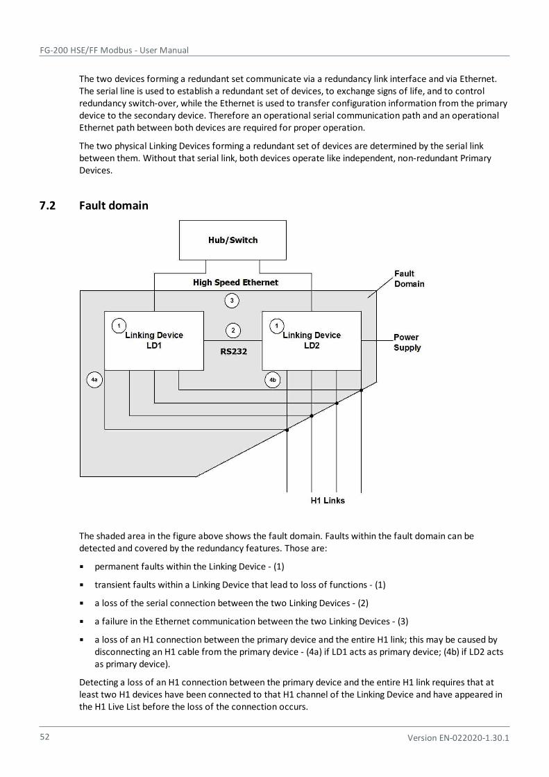
FG-200 HSE/FF Modbus - User Manual
52 Version EN-022020-1.30.1
The two devices forming a redundant set communicate via a redundancy link interface and via Ethernet.The serial line is used to establish a redundant set of devices, to exchange signs of life, and to controlredundancy switch-over, while the Ethernet is used to transfer configuration information from the primarydevice to the secondary device. Therefore an operational serial communication path and an operationalEthernet path between both devices are required for proper operation.
The two physical Linking Devices forming a redundant set of devices are determined by the serial linkbetween them. Without that serial link, both devices operate like independent, non-redundant PrimaryDevices.
7.2 Fault domain
The shaded area in the figure above shows the fault domain. Faults within the fault domain can bedetected and covered by the redundancy features. Those are:
permanent faults within the Linking Device - (1)
transient faults within a Linking Device that lead to loss of functions - (1)
a loss of the serial connection between the two Linking Devices - (2)
a failure in the Ethernet communication between the two Linking Devices - (3)
a loss of an H1 connection between the primary device and the entire H1 link; this may be caused bydisconnecting an H1 cable from the primary device - (4a) if LD1 acts as primary device; (4b) if LD2 actsas primary device).
Detecting a loss of an H1 connection between the primary device and the entire H1 link requires that atleast two H1 devices have been connected to that H1 channel of the Linking Device and have appeared inthe H1 Live List before the loss of the connection occurs.

Chapter 7 - Redundancy mode
Version EN-022020-1.30.1 53
Only one of the listed faults may be present at a time. Another fault cannot be tolerated until theredundant set has been repaired and a fully operational secondary device is available.
The following fault conditions cannot be detected and covered:
A loss of an H1 connection between the primary device and a subset of devices on an H1 link
A loss of an H1 connection between the secondary device and the entire H1 link or a subset of deviceson an H1 link.
The conditions for a switch-over from the primary device to the secondary device are listed below.
Transfer from primary device to secondary device
The primary device transfers its role to the secondary device
if Host system or configuration tool request to transfer the role
or the primary device detects a failure of its own Ethernet port
or the primary device detects a failure on at least one H1 interface
or the primary device detects a loss of the connection to all devices on an H1 link.1
1 This requires that at least two devices have been connected to that H1 channel of the Linking Device and haveappeared in the H1 Live List before the loss of the connection occurs.
The secondary device accepts the transfer
if its H1 interfaces are operational and faultless
and its Ethernet port is operational
and it has a valid configuration.
Take over of primary role
The secondary device takes over the primary role
if the serial connection to the primary device is lost
and it acts as Link Active Scheduler on all configured H1 links
and its Ethernet port is operational.
FG-200 HSE/FF Modbus - User Manual
54 Version EN-022020-1.30.1
Restoring redundancy
Only one of the listed faults may be present at a time. Another fault cannot be tolerated until theredundant set has been repaired and a fully operational secondary device is available.
The required measures for repairing the redundant set of devices depend on the present fault. For anoverview refer to Table 15.
Fault Measure of repair
Permanent fault within the FG-200 Replacement of the detective FG-200.
Transient fault within the FG-200 Restart of the FG-200 (performed automatically).
Loss of the serial connection between thetwo FG-200s
Re-establishment of the serial connection.
Loss of the Ethernet connection betweenthe two FG-200s.
Re-establishment of the Ethernet connection.
Loss of an H1 connection between thePrimary Devices and the entire H1 link
Re-establishment of the H1 connection.
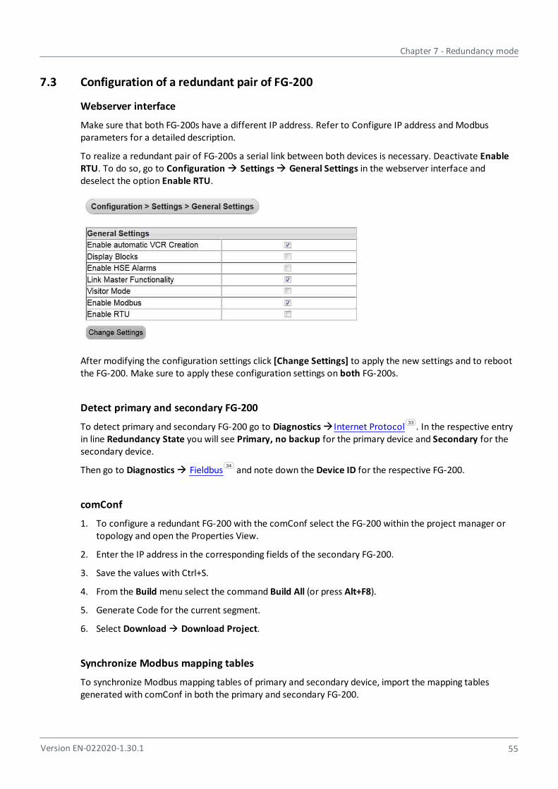
Chapter 7 - Redundancy mode
Version EN-022020-1.30.1 55
7.3 Configuration of a redundant pair of FG-200
Webserver interface
Make sure that both FG-200s have a different IP address. Refer to Configure IP address and Modbusparameters for a detailed description.
To realize a redundant pair of FG-200s a serial link between both devices is necessary. Deactivate EnableRTU. To do so, go to Configuration Settings General Settings in the webserver interface anddeselect the option Enable RTU.
After modifying the configuration settings click [Change Settings] to apply the new settings and to rebootthe FG-200. Make sure to apply these configuration settings on both FG-200s.
Detect primary and secondary FG-200
To detect primary and secondary FG-200 go to Diagnostics Internet Protocol . In the respective entryin line Redundancy State you will see Primary, no backup for the primary device and Secondary for thesecondary device.
Then go to Diagnostics Fieldbus and note down the Device ID for the respective FG-200.
comConf
1. To configure a redundant FG-200 with the comConf select the FG-200 within the project manager ortopology and open the Properties View.
2. Enter the IP address in the corresponding fields of the secondary FG-200.
3. Save the values with Ctrl+S.
4. From the Build menu select the command Build All (or press Alt+F8).
5. Generate Code for the current segment.
6. Select Download Download Project.
Synchronize Modbus mapping tables
To synchronize Modbus mapping tables of primary and secondary device, import the mapping tablesgenerated with comConf in both the primary and secondary FG-200.
33
34
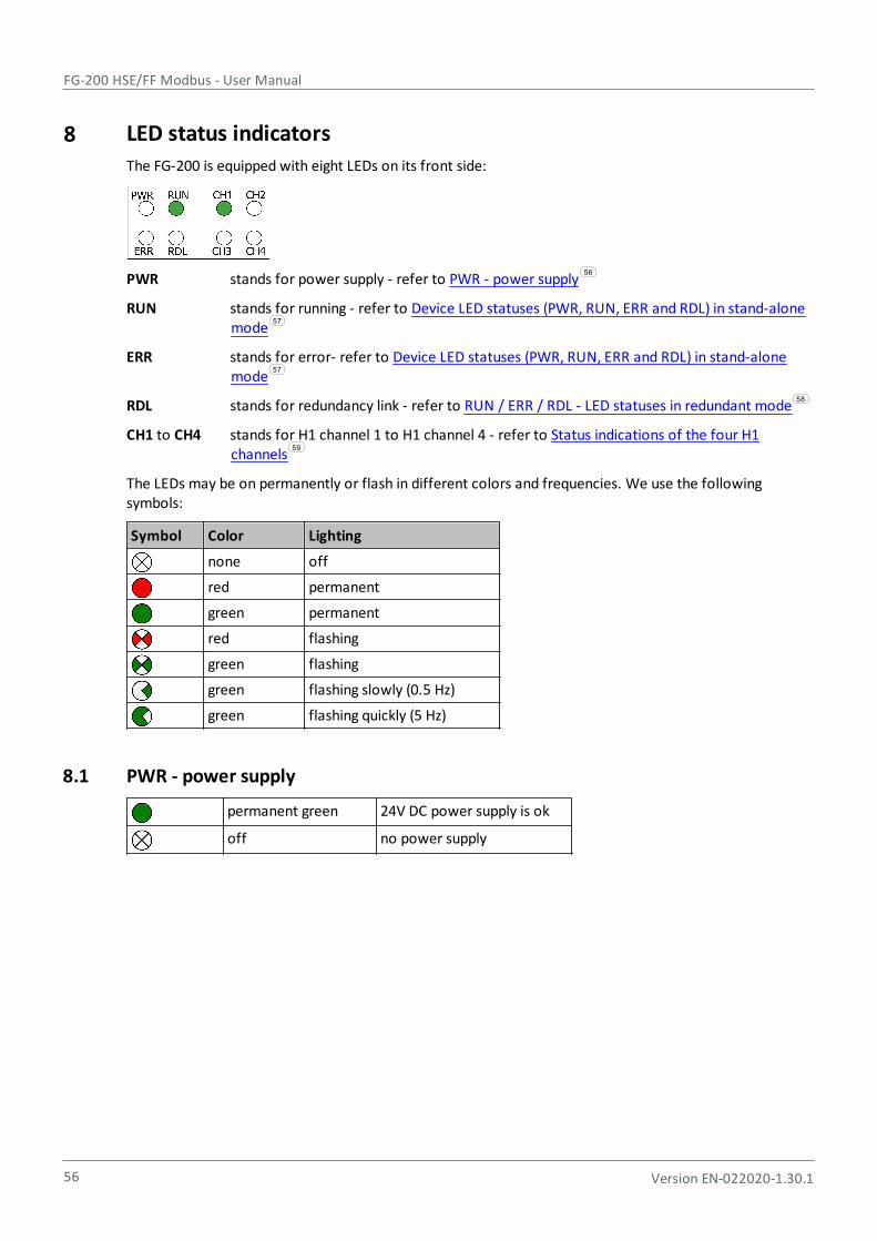
FG-200 HSE/FF Modbus - User Manual
56 Version EN-022020-1.30.1
8 LED status indicators
The FG-200 is equipped with eight LEDs on its front side:
PWR stands for power supply - refer to PWR - power supply
RUN stands for running - refer to Device LED statuses (PWR, RUN, ERR and RDL) in stand-alonemode
ERR stands for error- refer to Device LED statuses (PWR, RUN, ERR and RDL) in stand-alonemode
RDL stands for redundancy link - refer to RUN / ERR / RDL - LED statuses in redundant mode
CH1 to CH4 stands for H1 channel 1 to H1 channel 4 - refer to Status indications of the four H1channels
The LEDs may be on permanently or flash in different colors and frequencies. We use the followingsymbols:
Symbol Color Lighting
none off
red permanent
green permanent
red flashing
green flashing
green flashing slowly (0.5 Hz)
green flashing quickly (5 Hz)
8.1 PWR - power supply
permanent green 24V DC power supply is ok
off no power supply
56
57
57
58
59

Chapter 8 - LED status indicators
Version EN-022020-1.30.1 57
8.2 Device LED statuses (PWR, RUN, ERR and RDL) in stand-alone mode
The following table shows possible LED combinations in stand-alone mode:
LEDs Meaning
PWR RUN
green
ERR RDL
Start–up phase (approximately 7 seconds)
During this phase redundancy role is determined.
PWR RUN
green green
ERR RDL
Non redundant device, ready.
The device is operational; it is not part of a redundant set.
PWR RUN
green green
red
ERR RDL
Permanent hardware fault detection during startup.
A fatal error has been detected.
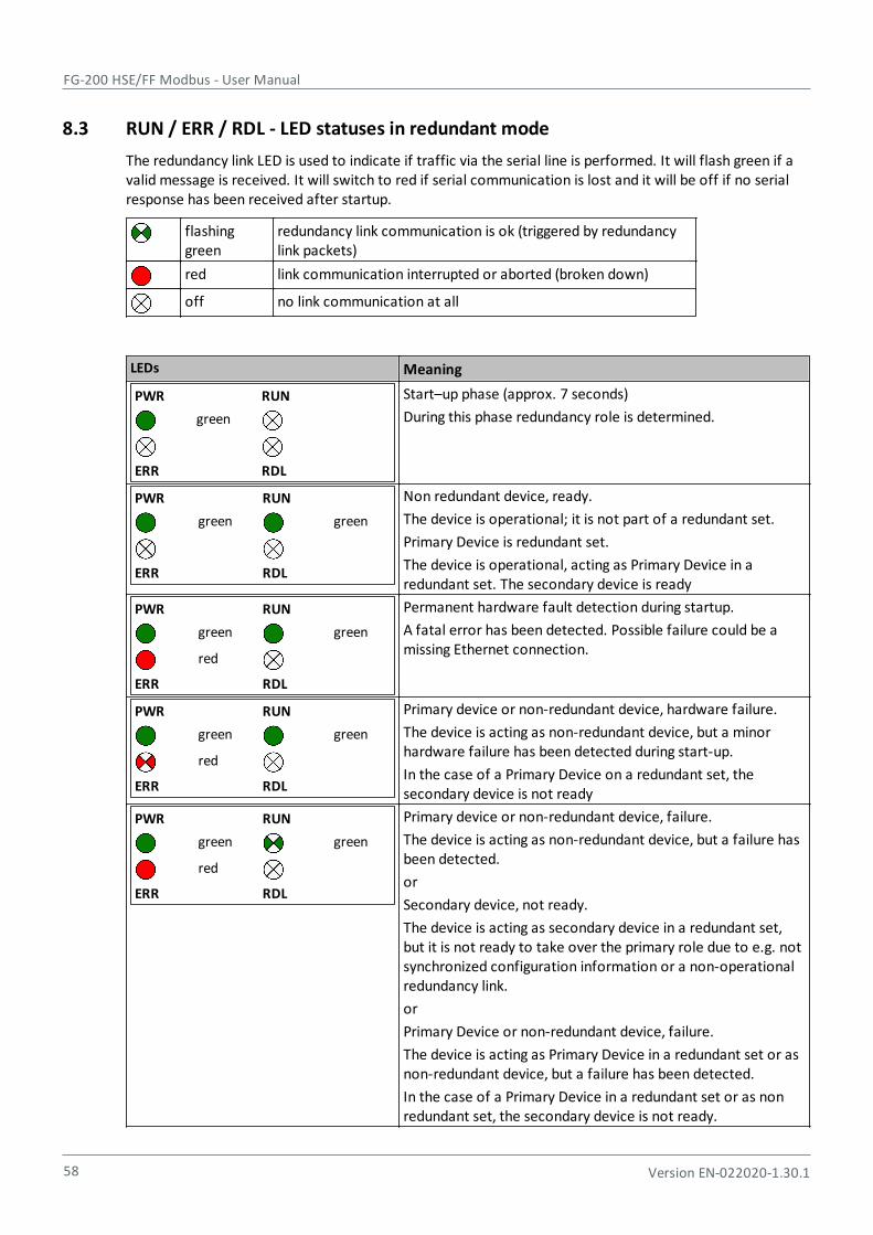
FG-200 HSE/FF Modbus - User Manual
58 Version EN-022020-1.30.1
8.3 RUN / ERR / RDL - LED statuses in redundant mode
The redundancy link LED is used to indicate if traffic via the serial line is performed. It will flash green if avalid message is received. It will switch to red if serial communication is lost and it will be off if no serialresponse has been received after startup.
flashinggreen
redundancy link communication is ok (triggered by redundancylink packets)
red link communication interrupted or aborted (broken down)
off no link communication at all
LEDs Meaning
PWR RUN
green
ERR RDL
Start–up phase (approx. 7 seconds)
During this phase redundancy role is determined.
PWR RUN
green green
ERR RDL
Non redundant device, ready.
The device is operational; it is not part of a redundant set.
Primary Device is redundant set.
The device is operational, acting as Primary Device in aredundant set. The secondary device is ready
PWR RUN
green green
red
ERR RDL
Permanent hardware fault detection during startup.
A fatal error has been detected. Possible failure could be amissing Ethernet connection.
PWR RUN
green green
red
ERR RDL
Primary device or non-redundant device, hardware failure.
The device is acting as non-redundant device, but a minorhardware failure has been detected during start-up.
In the case of a Primary Device on a redundant set, thesecondary device is not ready
PWR RUN
green green
red
ERR RDL
Primary device or non-redundant device, failure.
The device is acting as non-redundant device, but a failure hasbeen detected.
or
Secondary device, not ready.
The device is acting as secondary device in a redundant set,but it is not ready to take over the primary role due to e.g. notsynchronized configuration information or a non-operationalredundancy link.
or
Primary Device or non-redundant device, failure.
The device is acting as Primary Device in a redundant set or asnon-redundant device, but a failure has been detected.
In the case of a Primary Device in a redundant set or as nonredundant set, the secondary device is not ready.
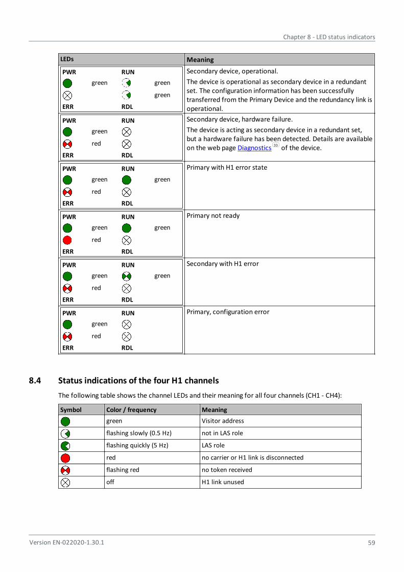
Chapter 8 - LED status indicators
Version EN-022020-1.30.1 59
LEDs Meaning
PWR RUN
green green
green
ERR RDL
Secondary device, operational.
The device is operational as secondary device in a redundantset. The configuration information has been successfullytransferred from the Primary Device and the redundancy link isoperational.
PWR RUN
green
red
ERR RDL
Secondary device, hardware failure.
The device is acting as secondary device in a redundant set,but a hardware failure has been detected. Details are availableon the web page Diagnostics of the device.
PWR RUN
green green
red
ERR RDL
Primary with H1 error state
PWR RUN
green green
red
ERR RDL
Primary not ready
PWR RUN
green green
red
ERR RDL
Secondary with H1 error
PWR RUN
green
red
ERR RDL
Primary, configuration error
8.4 Status indications of the four H1 channels
The following table shows the channel LEDs and their meaning for all four channels (CH1 - CH4):
Symbol Color / frequency Meaning
green Visitor address
flashing slowly (0.5 Hz) not in LAS role
flashing quickly (5 Hz) LAS role
red no carrier or H1 link is disconnected
flashing red no token received
off H1 link unused
33
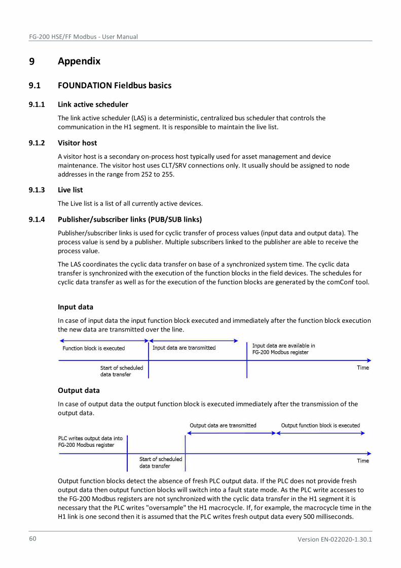
FG-200 HSE/FF Modbus - User Manual
60 Version EN-022020-1.30.1
9 Appendix
9.1 FOUNDATION Fieldbus basics
9.1.1 Link active scheduler
The link active scheduler (LAS) is a deterministic, centralized bus scheduler that controls thecommunication in the H1 segment. It is responsible to maintain the live list.
9.1.2 Visitor host
A visitor host is a secondary on-process host typically used for asset management and devicemaintenance. The visitor host uses CLT/SRV connections only. It usually should be assigned to nodeaddresses in the range from 252 to 255.
9.1.3 Live list
The Live list is a list of all currently active devices.
9.1.4 Publisher/subscriber links (PUB/SUB links)
Publisher/subscriber links is used for cyclic transfer of process values (input data and output data). Theprocess value is send by a publisher. Multiple subscribers linked to the publisher are able to receive theprocess value.
The LAS coordinates the cyclic data transfer on base of a synchronized system time. The cyclic datatransfer is synchronized with the execution of the function blocks in the field devices. The schedules forcyclic data transfer as well as for the execution of the function blocks are generated by the comConf tool.
Input data
In case of input data the input function block executed and immediately after the function block executionthe new data are transmitted over the line.
Output data
In case of output data the output function block is executed immediately after the transmission of theoutput data.
Output function blocks detect the absence of fresh PLC output data. If the PLC does not provide freshoutput data then output function blocks will switch into a fault state mode. As the PLC write accesses tothe FG-200 Modbus registers are not synchronized with the cyclic data transfer in the H1 segment it isnecessary that the PLC writes "oversample" the H1 macrocycle. If, for example, the macrocycle time in theH1 link is one second then it is assumed that the PLC writes fresh output data every 500 milliseconds.
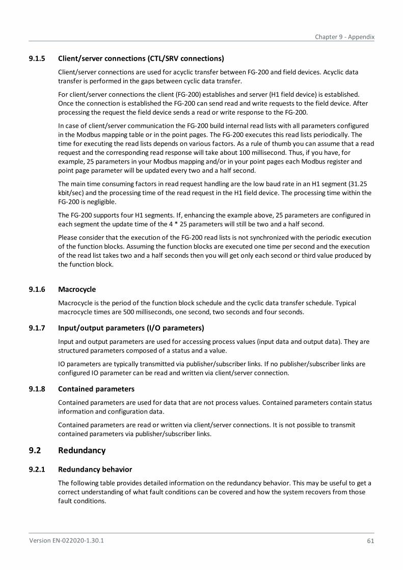
Chapter 9 - Appendix
Version EN-022020-1.30.1 61
9.1.5 Client/server connections (CTL/SRV connections)
Client/server connections are used for acyclic transfer between FG-200 and field devices. Acyclic datatransfer is performed in the gaps between cyclic data transfer.
For client/server connections the client (FG-200) establishes and server (H1 field device) is established.Once the connection is established the FG-200 can send read and write requests to the field device. Afterprocessing the request the field device sends a read or write response to the FG-200.
In case of client/server communication the FG-200 build internal read lists with all parameters configuredin the Modbus mapping table or in the point pages. The FG-200 executes this read lists periodically. Thetime for executing the read lists depends on various factors. As a rule of thumb you can assume that a readrequest and the corresponding read response will take about 100 millisecond. Thus, if you have, forexample, 25 parameters in your Modbus mapping and/or in your point pages each Modbus register andpoint page parameter will be updated every two and a half second.
The main time consuming factors in read request handling are the low baud rate in an H1 segment (31.25kbit/sec) and the processing time of the read request in the H1 field device. The processing time within theFG-200 is negligible.
The FG-200 supports four H1 segments. If, enhancing the example above, 25 parameters are configured ineach segment the update time of the 4 * 25 parameters will still be two and a half second.
Please consider that the execution of the FG-200 read lists is not synchronized with the periodic executionof the function blocks. Assuming the function blocks are executed one time per second and the executionof the read list takes two and a half seconds then you will get only each second or third value produced bythe function block.
9.1.6 Macrocycle
Macrocycle is the period of the function block schedule and the cyclic data transfer schedule. Typicalmacrocycle times are 500 milliseconds, one second, two seconds and four seconds.
9.1.7 Input/output parameters (I/O parameters)
Input and output parameters are used for accessing process values (input data and output data). They arestructured parameters composed of a status and a value.
IO parameters are typically transmitted via publisher/subscriber links. If no publisher/subscriber links areconfigured IO parameter can be read and written via client/server connection.
9.1.8 Contained parameters
Contained parameters are used for data that are not process values. Contained parameters contain statusinformation and configuration data.
Contained parameters are read or written via client/server connections. It is not possible to transmitcontained parameters via publisher/subscriber links.
9.2 Redundancy
9.2.1 Redundancy behavior
The following table provides detailed information on the redundancy behavior. This may be useful to get acorrect understanding of what fault conditions can be covered and how the system recovers from thosefault conditions.

FG-200 HSE/FF Modbus - User Manual
62 Version EN-022020-1.30.1
In any case, the fully redundant state is obtained again when the secondary device indicates"operational" (RUN-LED flashing) and its H1 live lists are complete. In highly populated, tightly configuredH1 links it may take several minutes to acquire the live lists. Before the live lists are completed, redundancyswitching is possible but client server connections can only be established to H1 devices which are in thelive list.
Any further error that occurs before the fully redundant state is reached may cause the system to fail.
Primary device failure due to permanent or transient hardware or software fault (1):
Fault detection Device fails completely or software watchdog expires or hardware watchdogexpires or exception occurs or failure in H1 interface detected.
Fault treatment Primary role actively transferred to or taken by redundant system
Effect Redundancy switch-over. System degrades to non–redundant system.
Repair measure Transient fault: Automatic reboot
Permanent fault: replace device
Secondary service will reboot and receive configuration data from primary device.
Ethernet cable broken between primary device and Ethernet hub/switch (2)
Fault detection Bad link status of Ethernet port detected. Detection time less than 500 ms.
Fault treatment Primary role actively transferred to redundant device.
Effect Redundancy switch-over. System degrades to non-redundant system.
Repair measure Repair or reconnect Ethernet cable.
Secondary device will reboot and receive configuration data from primary device.
H1 cable broken between primary device and H1 network (3)
Fault detection Empty live list detected on one H1 port or primary device while secondary devicestill has non-empty live list. Due to the H1 protocol it may take some seconds.Until the live list becomes empty. Detection occurs only if in primary device andsecondary device the number of active H1 devices in the live list has exceeded thethreshold of one.
Fault treatment Primary role actively transferred to redundant device, so that access to H1 ispossible again.
Effect Redundancy switch-over. No redundancy concerning the affected H1 link.
Repair measure Repair or reconnect H1 cable.
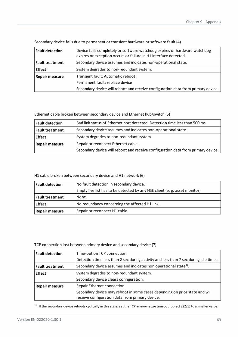
Chapter 9 - Appendix
Version EN-022020-1.30.1 63
Secondary device fails due to permanent or transient hardware or software fault (4)
Fault detection Device fails completely or software watchdog expires or hardware watchdogexpires or exception occurs or failure in H1 interface detected.
Fault treatment Secondary device assumes and indicates non-operational state.
Effect System degrades to non-redundant system.
Repair measure Transient fault: Automatic reboot
Permanent fault: replace device
Secondary device will reboot and receive configuration data from primary device.
Ethernet cable broken between secondary device and Ethernet hub/switch (5)
Fault detection Bad link status of Ethernet port detected. Detection time less than 500 ms.
Fault treatment Secondary device assumes and indicates non-operational state.
Effect System degrades to non-redundant system.
Repair measure Repair or reconnect Ethernet cable.
Secondary device will reboot and receive configuration data from primary device.
H1 cable broken between secondary device and H1 network (6)
Fault detection No fault detection in secondary device.
Empty live list has to be detected by any HSE client (e. g. asset monitor).
Fault treatment None.
Effect No redundancy concerning the affected H1 link.
Repair measure Repair or reconnect H1 cable.
TCP connection lost between primary device and secondary device (7)
Fault detection Time-out on TCP connection.
Detection time less than 2 sec during activity and less than 7 sec during idle times.
Fault treatment Secondary device assumes and indicates non operational state1).
Effect System degrades to non-redundant system.
Secondary device clears configuration.
Repair measure Repair Ethernet connection.
Secondary device may reboot in some cases depending on prior state and willreceive configuration data from primary device.
1) If the secondary device reboots cyclically in this state, set the TCP acknowledge timeout (object 22223) to a smaller value.
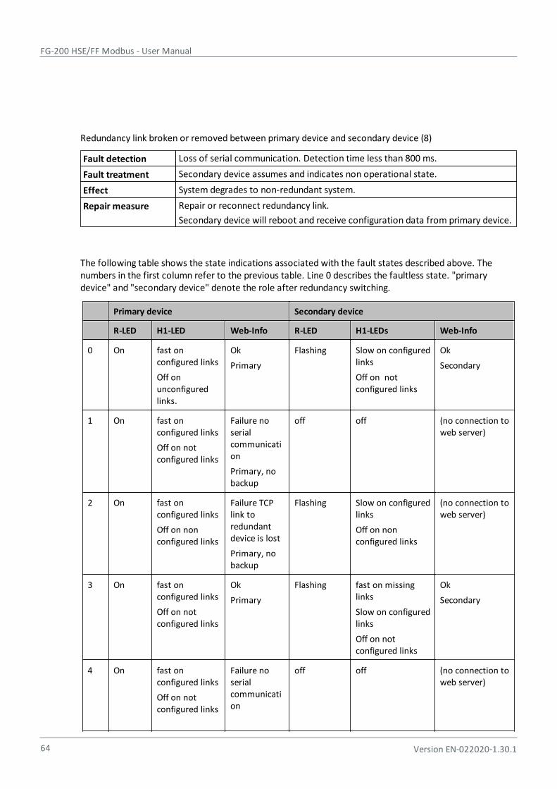
FG-200 HSE/FF Modbus - User Manual
64 Version EN-022020-1.30.1
Redundancy link broken or removed between primary device and secondary device (8)
Fault detection Loss of serial communication. Detection time less than 800 ms.
Fault treatment Secondary device assumes and indicates non operational state.
Effect System degrades to non-redundant system.
Repair measure Repair or reconnect redundancy link.
Secondary device will reboot and receive configuration data from primary device.
The following table shows the state indications associated with the fault states described above. Thenumbers in the first column refer to the previous table. Line 0 describes the faultless state. "primarydevice" and "secondary device" denote the role after redundancy switching.
Primary device Secondary device
R-LED H1-LED Web-Info R-LED H1-LEDs Web-Info
0 On fast onconfigured links
Off onunconfiguredlinks.
Ok
Primary
Flashing Slow on configuredlinks
Off on notconfigured links
Ok
Secondary
1 On fast onconfigured links
Off on notconfigured links
Failure noserialcommunication
Primary, nobackup
off off (no connection toweb server)
2 On fast onconfigured links
Off on nonconfigured links
Failure TCPlink toredundantdevice is lost
Primary, nobackup
Flashing Slow on configuredlinks
Off on nonconfigured links
(no connection toweb server)
3 On fast onconfigured links
Off on notconfigured links
Ok
Primary
Flashing fast on missinglinks
Slow on configuredlinks
Off on notconfigured links
Ok
Secondary
4 On fast onconfigured links
Off on notconfigured links
Failure noserialcommunication
off off (no connection toweb server)
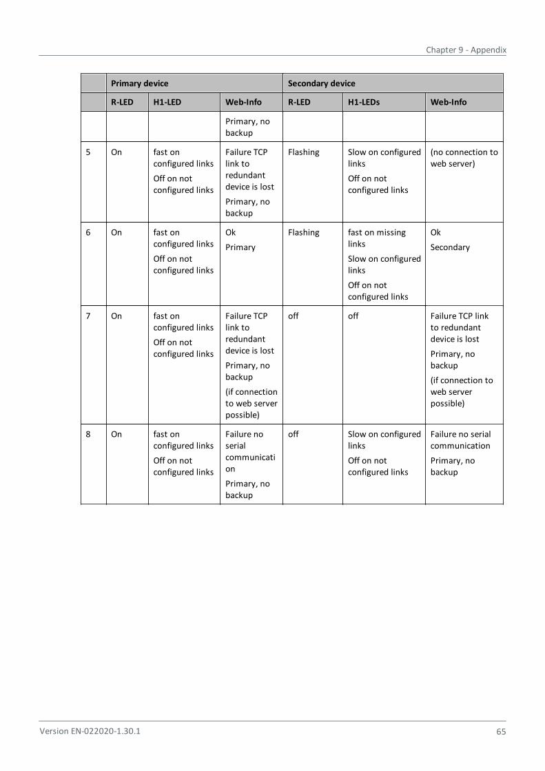
Chapter 9 - Appendix
Version EN-022020-1.30.1 65
Primary device Secondary device
R-LED H1-LED Web-Info R-LED H1-LEDs Web-Info
Primary, nobackup
5 On fast onconfigured links
Off on notconfigured links
Failure TCPlink toredundantdevice is lost
Primary, nobackup
Flashing Slow on configuredlinks
Off on notconfigured links
(no connection toweb server)
6 On fast onconfigured links
Off on notconfigured links
Ok
Primary
Flashing fast on missinglinks
Slow on configuredlinks
Off on notconfigured links
Ok
Secondary
7 On fast onconfigured links
Off on notconfigured links
Failure TCPlink toredundantdevice is lost
Primary, nobackup
(if connectionto web serverpossible)
off off Failure TCP linkto redundantdevice is lost
Primary, nobackup
(if connection toweb serverpossible)
8 On fast onconfigured links
Off on notconfigured links
Failure noserialcommunication
Primary, nobackup
off Slow on configuredlinks
Off on notconfigured links
Failure no serialcommunication
Primary, nobackup
FG-200 HSE/FF Modbus - User Manual
66 Version EN-022020-1.30.1
9.2.2 Duration of redundancy switch-over
Switch-over duration PUB/SUB links
During redundancy switch-over, the activity on H1 links is interrupted. From the perspective of a single H1device, PUB/SUB links are interrupted for a period of time that is composed of the following times:
fault detection time t fd
redundancy switching time t rs
macro cycle duration t mc
The time of inactivity due to redundancy switch-over for a single process value is therefore:
time of inactivity =t fd + t rs + t mc
compared to t mc during regular operation.
The fault detection time is:
t fd =800 ms if the primary device fails.
t fd =1500 ms if the Ethernet connection on the primary device is removed.
The redundancy switching time is:
t rs =500 ms.
The macrocycle duration depends on the configuration and is usually in the range of 500 ms to 2 seconds.
Switch-over duration for CLT/SRV connections
In case of CLT/SRV connections the switch will take about one minute.
If contained parameters such as BLOCK_ERR or channel are accessed, it will take about one minute untilthe registers in the secondary FG-200 show the current parameter values.
9.2.3 Replace a defective FG-200 in a redundant set
For replacing a defective FG-200 in a redundant set of FG-200s, perform the following steps:
1. Identify the defective FG-200. Refer to Status indicators - LEDs .
2. Remove the power terminal block from the FG-200.
3. Remove the redundancy link interface cable and the Ethernet cable.
4. If not indicated on the cable, make a note to which channel each H1 link is connected. Then removethe H1 terminal blocks.
5. Make sure that the new FG-200 has the same IP configuration (IP address and subnet mask) as thereplaced defective device. See Internet Protocol submenu for more information.
6. Replace the defective FG-200.
7. Plug in the H1 terminal blocks. Make sure to use the same allocation as before.
8. Connect the Ethernet cable and the redundancy link interface cable.
9. Make sure that the redundancy link interface cable is connected before plugging in the power terminalblock.
60
61
61
56
38

Chapter 9 - Appendix
Version EN-022020-1.30.1 67
If the replaced FG-200 is powered while the serial link is missing, it will behave like an independent,non-redundant primary device. If in this case the FG-200 has a valid (possibly unknown) configuration,it might use H1 node addresses which are already in use on the H1 links. This will disturb or interruptcommunication and application processing on the H1 links.
10. Plug in the power terminal block. The boot process and the download of the configuration informationtake about 1 minute. For indication of proper operation as a secondary device refer to Statusindicators - LEDs .
56
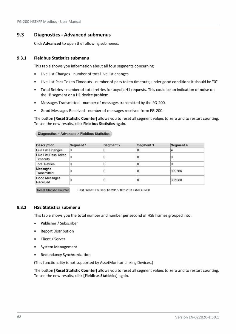
FG-200 HSE/FF Modbus - User Manual
68 Version EN-022020-1.30.1
9.3 Diagnostics - Advanced submenus
Click Advanced to open the following submenus:
9.3.1 Fieldbus Statistics submenu
This table shows you information about all four segments concerning
Live List Changes - number of total live list changes
Live List Pass Token Timeouts - number of pass token timeouts; under good conditions it should be "0"
Total Retries - number of total retries for acyclic H1 requests. This could be an indication of noise onthe H! segment or a H1 device problem.
Messages Transmitted - number of messages transmitted by the FG-200.
Good Messages Received - number of messages received from FG-200.
The button [Reset Statistic Counter] allows you to reset all segment values to zero and to restart counting.To see the new results, click Fieldbus Statistics again.
9.3.2 HSE Statistics submenu
This table shows you the total number and number per second of HSE frames grouped into:
Publisher / Subscriber
Report Distribution
Client / Server
System Management
Redundancy Synchronization
(This functionality is not supported by AssetMonitor Linking Devices.)
The button [Reset Statistic Counter] allows you to reset all segment values to zero and to restart counting.To see the new results, click [Fieldbus Statistics] again.
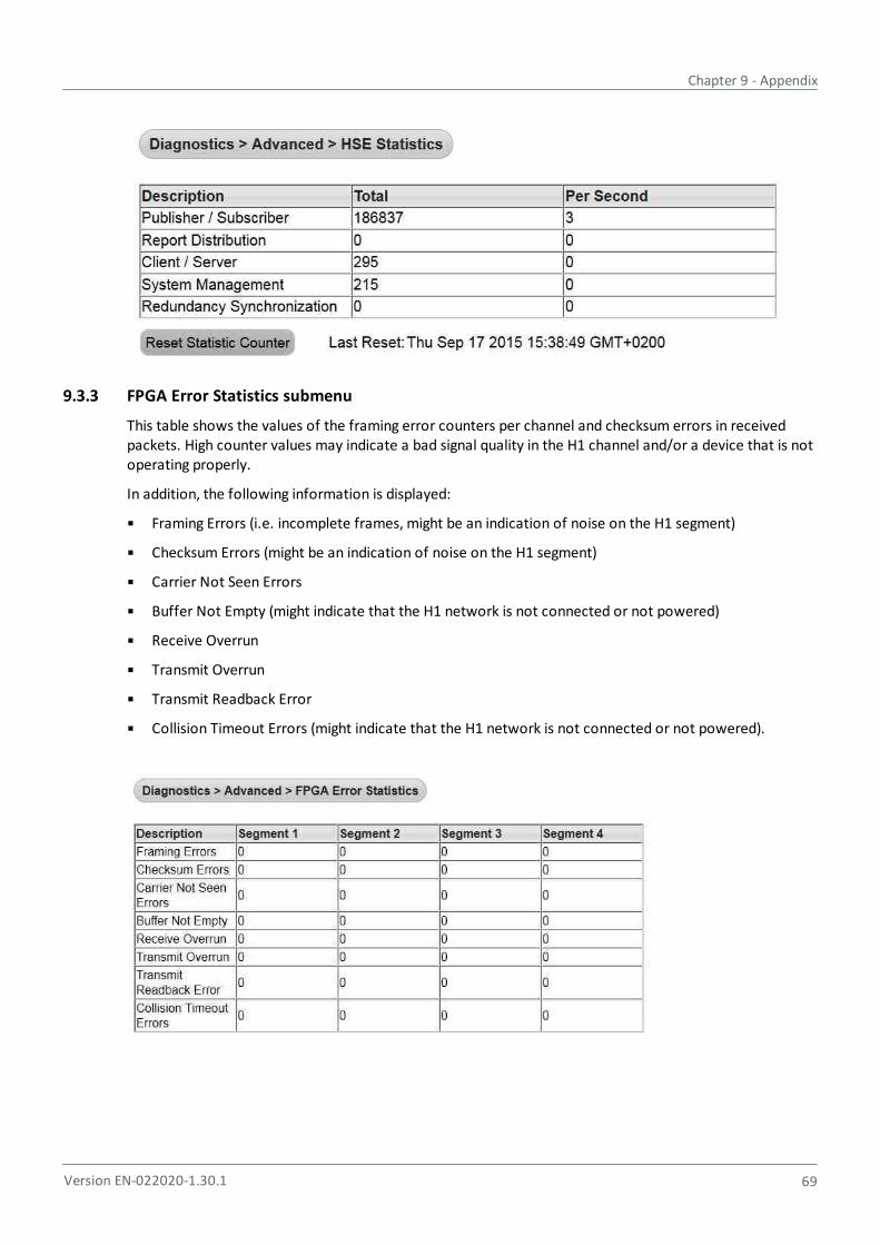
Chapter 9 - Appendix
Version EN-022020-1.30.1 69
9.3.3 FPGA Error Statistics submenu
This table shows the values of the framing error counters per channel and checksum errors in receivedpackets. High counter values may indicate a bad signal quality in the H1 channel and/or a device that is notoperating properly.
In addition, the following information is displayed:
Framing Errors (i.e. incomplete frames, might be an indication of noise on the H1 segment)
Checksum Errors (might be an indication of noise on the H1 segment)
Carrier Not Seen Errors
Buffer Not Empty (might indicate that the H1 network is not connected or not powered)
Receive Overrun
Transmit Overrun
Transmit Readback Error
Collision Timeout Errors (might indicate that the H1 network is not connected or not powered).
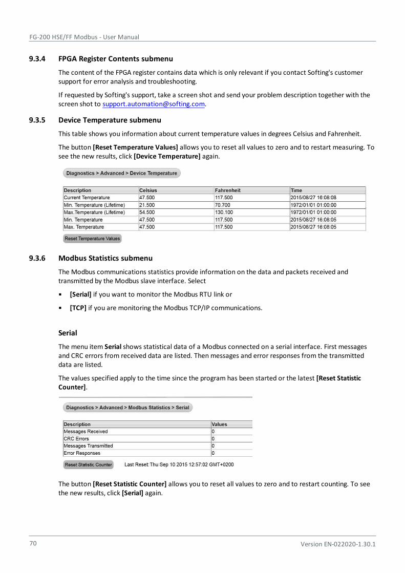
FG-200 HSE/FF Modbus - User Manual
70 Version EN-022020-1.30.1
9.3.4 FPGA Register Contents submenu
The content of the FPGA register contains data which is only relevant if you contact Softing's customersupport for error analysis and troubleshooting.
If requested by Softing's support, take a screen shot and send your problem description together with thescreen shot to [email protected].
9.3.5 Device Temperature submenu
This table shows you information about current temperature values in degrees Celsius and Fahrenheit.
The button [Reset Temperature Values] allows you to reset all values to zero and to restart measuring. Tosee the new results, click [Device Temperature] again.
9.3.6 Modbus Statistics submenu
The Modbus communications statistics provide information on the data and packets received andtransmitted by the Modbus slave interface. Select
[Serial] if you want to monitor the Modbus RTU link or
[TCP] if you are monitoring the Modbus TCP/IP communications.
Serial
The menu item Serial shows statistical data of a Modbus connected on a serial interface. First messagesand CRC errors from received data are listed. Then messages and error responses from the transmitteddata are listed.
The values specified apply to the time since the program has been started or the latest [Reset StatisticCounter].
The button [Reset Statistic Counter] allows you to reset all values to zero and to restart counting. To seethe new results, click [Serial] again.

Chapter 9 - Appendix
Version EN-022020-1.30.1 71
TCP
The menu item TCP shows statistical data of a Modbus connected using TCP. First received andtransmitted messages are listed. Then the error responses are counted. Finally open and acceptedconnections are listed.
The button [Reset Counts] allows you to reset all values to zero and to restart counting. To see the newresults, click [TCP] again.
9.4 Coding of bit fields
Parameter BLOCK_ERR
No error 0x0000
Out Of Service 0x0001
Power up 0x0002
Device needs maintenance 0x0004
Readback check failed 0x0008
Lost nv data 0x0010
Lost static data 0x0020
Memory failure 0x0040
Output failure 0x0080
Input failure 0x0100
Dev needs maint soon 0x0200
Dev fault state set 0x0400
Local override 0x0800
Simulate active 0x1000
Link config err 0x2000
Block config err 0x4000
Other 0x8000

FG-200 HSE/FF Modbus - User Manual
72 Version EN-022020-1.30.1
Parameter MODE_BLK:
Out Of Service 0x01
Initialization Manual 0x02
Local Override 0x04
Manual 0x08
Auto 0x10
Cascade 0x20
Remote-Cascade 0x40
Remote-Output 0x80
Modbus Register 16 Bit register contains target mode in High Byte, actual mode in low byte.
Example: Modbus value 0x1001 means: target mode = Auto, actual mode = Out Of Service
Field Diagnostics (Parameter FD_FAIL, FD_OFFSPEC, FD_CHECK, FD_MAINT)
The bit fields are vendor specific and not specified by FIELDBUS Foundation except the leastsignificant bit (LSB). The LSB indicates the check function to be active. The check function istypically mapped to the FD_CHECK parameter but may also be mapped to any of the otherFD_xxx parameters.
The value for LSB is 0x80000000, the value for the most significant bit (MSB) is 0x00000001
9.5 Modbus exception responses
ExceptionCode = 02
The FG-200 will send an exception response with [ExceptionCode = 02] if [start address] or [start address +quantity of registers] is not OK.
ExceptionCode = 04
The FG-200 will send an exception response with [ExceptionCode = 04] if one of the requested registersdoes not contain valid data. Please note that after power-on the FG-200 responds with [ExceptionCode =04] until all requested data are read from the connected H1 field devices.
Chapter 9 - Appendix
Version EN-022020-1.30.1 73
9.6 Assign a second (local) IP address under Windows 8.1
1. Open the Desktop
2. Press the Windows start key and select Control Panel.
3. Select Network and Internet.
4. Open Network and Sharing Center.
5. Click Connections.
6. In the Connection Status window click Properties.
7. In the item connection list select Internet Protocol Version 4 (TCP/IPv4).
8. Click Properties. In the General dialog, the regular (first) IP address, the subnet mask and the standardgateway are shown.
9. Click Advanced to add a second IP address. Then click [Add] in the IP Addresses dialog.
10. Enter the IP address and the subnet mask.
11. Click [Add].
12. Then confirm all open dialogs with [OK].

FG-200 HSE/FF Modbus - User Manual
74 Version EN-022020-1.30.1
10 ATEX Type Examination Certificate

Chapter 10 - ATEX Type Examination Certificate
Version EN-022020-1.30.1 75

FG-200 HSE/FF Modbus - User Manual
76 Version EN-022020-1.30.1

Chapter 11 - UL Certificate of Compliance
Version EN-022020-1.30.1 77
11 UL Certificate of Compliance
FG-200 HSE/FF Modbus - User Manual
78 Version EN-022020-1.30.1
12 Declarations of conformity
This device is compliant with EC directive 2014/30/EG, "Electromagnetic Compatibility" (EMC directive)and meets the following requirements:
EN 55011 Industrial, scientific and medical (ISM) devices - radio disturbance - limits and methods of measurement
EN 55032 Electromagnetic compatibility of multimedia equipment (MME) and interference emission
EN 61000-6-4 Electromagnetic compatibility (EMC); Part 6-4: generic standard – emission for industrial environments
EN 61000-6-2 Electromagnetic compatibility (EMC); Part 6-2: generic standard - immunity for industrial environments
NoteTo fulfill the EMC requirements, the other components of your installation (DC adapter,Industrial Ethernet devices, etc.) also have to meet the EMC requirements. A shielded cablemust be used. In addition, the cable shield must be grounded properly.
CAUTIONThis is a Class A product. In a domestic environment this product may cause radiointerference in which case the user may be required to take adequate measures!
CEA Declaration of Conformity in compliance with the above standards has been made and canbe requested from Softing Industrial Automation.
ROHS
This product is ROHS compliant.
FCC
This equipment has been tested and found to comply with the limits for a Class A digitaldevice, under part 15 of the FCC Rules. These limits are designed to provide reasonableprotection against harmful interference when the equipment is operated in a commercialenvironment. This equipment generates, uses, and can radiate radio frequency energy and, ifnot installed and used in accordance with the instruction manual, may cause harmfulinterference to radio communications.
VCCI
This Class A product conforms to the regulations of Voluntary Control Council forInterference (VCCI) by Information Technology Equipment.
WEEE
Electrical and electronic equipment must be disposed of separately from normal waste at theend of its operational lifetime. Packaging material and worn components shall be disposed ofaccording to the regulations applicable in the country of installation.

This page is intentionally left blank.
Version EN-022020-1.30.1 79

Richard-Reitzner-Allee 685540 Haar / Germanyhttps://industrial.softing.com
Softing Industrial Automation GmbH
+ 49 89 45 656-340+ 49 89 45 [email protected]