FFmpeg Filters Documentation
417
FFmpeg Filters Documentation Table of Contents 1 Description 2 Filtering Introduction 3 graph2dot 4 Filtergraph description 4.1 Filtergraph syntax 4.2 Notes on filtergraph escaping 5 Timeline editing 6 Options for filters with several inputs (framesync) 7 Audio Filters 7.1 acompressor 7.2 acontrast 7.3 acopy 7.4 acrossfade 7.4.1 Examples 7.5 acrusher 7.6 adelay 7.6.1 Examples 7.7 aecho 7.7.1 Examples 7.8 aemphasis 7.9 aeval 7.9.1 Examples 7.10 afade 7.10.1 Examples 7.11 afftfilt 7.11.1 Examples 7.12 afir 7.12.1 Examples 7.13 aformat 7.14 agate 7.15 aiir 7.15.1 Examples 7.16 alimiter 7.17 allpass 7.17.1 Commands 7.18 aloop 7.19 amerge 7.19.1 Examples 7.20 amix
Transcript of FFmpeg Filters Documentation
FFmpeg Filters Documentation
Table of Contents1 Description 2 Filtering Introduction 3 graph2dot 4 Filtergraph description
4.1 Filtergraph syntax 4.2 Notes on filtergraph escaping
5 Timeline editing 6 Options for filters with several inputs (framesync) 7 Audio Filters
7.1 acompressor 7.2 acontrast 7.3 acopy 7.4 acrossfade
7.4.1 Examples 7.5 acrusher 7.6 adelay
7.6.1 Examples 7.7 aecho
7.7.1 Examples 7.8 aemphasis 7.9 aeval
7.9.1 Examples 7.10 afade
7.10.1 Examples 7.11 afftfilt
7.11.1 Examples 7.12 afir
7.12.1 Examples 7.13 aformat 7.14 agate 7.15 aiir
7.15.1 Examples 7.16 alimiter 7.17 allpass
7.17.1 Commands 7.18 aloop 7.19 amerge
7.19.1 Examples 7.20 amix

7.21 anequalizer 7.21.1 Examples 7.21.2 Commands
7.22 anull 7.23 apad
7.23.1 Examples 7.24 aphaser 7.25 apulsator 7.26 aresample
7.26.1 Examples 7.27 areverse
7.27.1 Examples 7.28 asetnsamples 7.29 asetrate 7.30 ashowinfo 7.31 astats 7.32 atempo
7.32.1 Examples 7.33 atrim 7.34 bandpass
7.34.1 Commands 7.35 bandreject
7.35.1 Commands 7.36 bass
7.36.1 Commands 7.37 biquad
7.37.1 Commands 7.38 bs2b 7.39 channelmap
7.39.1 Examples 7.40 channelsplit
7.40.1 Examples 7.41 chorus
7.41.1 Examples 7.42 compand
7.42.1 Examples 7.43 compensationdelay 7.44 crossfeed 7.45 crystalizer 7.46 dcshift 7.47 drmeter 7.48 dynaudnorm 7.49 earwax
7.50 equalizer 7.50.1 Examples 7.50.2 Commands
7.51 extrastereo 7.52 firequalizer
7.52.1 Examples 7.53 flanger 7.54 haas 7.55 hdcd 7.56 headphone
7.56.1 Examples 7.57 highpass
7.57.1 Commands 7.58 join 7.59 ladspa
7.59.1 Examples 7.59.2 Commands
7.60 loudnorm 7.61 lowpass
7.61.1 Examples 7.61.2 Commands
7.62 lv2 7.62.1 Examples
7.63 mcompand 7.64 pan
7.64.1 Mixing examples 7.64.2 Remapping examples
7.65 replaygain 7.66 resample 7.67 rubberband 7.68 sidechaincompress
7.68.1 Examples 7.69 sidechaingate 7.70 silencedetect
7.70.1 Examples 7.71 silenceremove
7.71.1 Examples 7.72 sofalizer
7.72.1 Examples 7.73 stereotools
7.73.1 Examples 7.74 stereowiden 7.75 superequalizer
7.76 surround 7.77 treble
7.77.1 Commands 7.78 tremolo 7.79 vibrato 7.80 volume
7.80.1 Commands 7.80.2 Examples
7.81 volumedetect 7.81.1 Examples
8 Audio Sources 8.1 abuffer
8.1.1 Examples 8.2 aevalsrc
8.2.1 Examples 8.3 anullsrc
8.3.1 Examples 8.4 flite
8.4.1 Examples 8.5 anoisesrc
8.5.1 Examples 8.6 hilbert 8.7 sine
8.7.1 Examples 9 Audio Sinks
9.1 abuffersink 9.2 anullsink
10 Video Filters 10.1 alphaextract 10.2 alphamerge 10.3 ass 10.4 atadenoise 10.5 avgblur 10.6 bbox 10.7 bitplanenoise 10.8 blackdetect 10.9 blackframe 10.10 blend, tblend
10.10.1 Examples 10.11 boxblur
10.11.1 Examples 10.12 bwdif 10.13 chromakey
10.13.1 Examples 10.14 ciescope 10.15 codecview
10.15.1 Examples 10.16 colorbalance
10.16.1 Examples 10.17 colorkey
10.17.1 Examples 10.18 colorlevels
10.18.1 Examples 10.19 colorchannelmixer
10.19.1 Examples 10.20 colormatrix 10.21 colorspace 10.22 convolution
10.22.1 Examples 10.23 convolve 10.24 copy 10.25 coreimage
10.25.1 Examples 10.26 crop
10.26.1 Examples 10.26.2 Commands
10.27 cropdetect 10.28 curves
10.28.1 Examples 10.29 datascope 10.30 dctdnoiz
10.30.1 Examples 10.31 deband 10.32 decimate 10.33 deconvolve 10.34 deflate 10.35 deflicker 10.36 dejudder 10.37 delogo
10.37.1 Examples 10.38 deshake 10.39 despill 10.40 detelecine 10.41 dilation 10.42 displace
10.42.1 Examples
10.43 drawbox 10.43.1 Examples
10.44 drawgrid 10.44.1 Examples
10.45 drawtext 10.45.1 Syntax 10.45.2 Text expansion 10.45.3 Examples
10.46 edgedetect 10.46.1 Examples
10.47 eq 10.47.1 Commands
10.48 erosion 10.49 extractplanes
10.49.1 Examples 10.50 elbg 10.51 entropy 10.52 fade
10.52.1 Examples 10.53 fftfilt
10.53.1 Examples 10.54 field 10.55 fieldhint 10.56 fieldmatch
10.56.1 p/c/n/u/b meaning 10.56.1.1 p/c/n 10.56.1.2 u/b
10.56.2 Examples 10.57 fieldorder 10.58 fifo, afifo 10.59 fillborders 10.60 find_rect
10.60.1 Examples 10.61 cover_rect
10.61.1 Examples 10.62 floodfill 10.63 format
10.63.1 Examples 10.64 fps
10.64.1 Examples 10.65 framepack 10.66 framerate 10.67 framestep
10.68 frei0r 10.68.1 Examples
10.69 fspp 10.70 gblur 10.71 geq
10.71.1 Examples 10.72 gradfun
10.72.1 Examples 10.73 haldclut
10.73.1 Workflow examples 10.73.1.1 Hald CLUT video stream 10.73.1.2 Hald CLUT with preview
10.74 hflip 10.75 histeq 10.76 histogram
10.76.1 Examples 10.77 hqdn3d 10.78 hwdownload 10.79 hwmap 10.80 hwupload 10.81 hwupload_cuda 10.82 hqx 10.83 hstack 10.84 hue
10.84.1 Examples 10.84.2 Commands
10.85 hysteresis 10.86 idet 10.87 il 10.88 inflate 10.89 interlace 10.90 kerndeint
10.90.1 Examples 10.91 lenscorrection
10.91.1 Options 10.92 libvmaf 10.93 limiter 10.94 loop 10.95 lut3d 10.96 lumakey 10.97 lut, lutrgb, lutyuv
10.97.1 Examples 10.98 lut2, tlut2
10.98.1 Examples 10.99 maskedclamp 10.100 maskedmerge 10.101 mcdeint 10.102 mergeplanes
10.102.1 Examples 10.103 mestimate 10.104 midequalizer 10.105 minterpolate 10.106 mix 10.107 mpdecimate 10.108 negate 10.109 nlmeans 10.110 nnedi 10.111 noformat
10.111.1 Examples 10.112 noise
10.112.1 Examples 10.113 normalize
10.113.1 Examples 10.114 null 10.115 ocr 10.116 ocv
10.116.1 dilate 10.116.2 erode 10.116.3 smooth
10.117 oscilloscope 10.117.1 Examples
10.118 overlay 10.118.1 Commands 10.118.2 Examples
10.119 owdenoise 10.120 pad
10.120.1 Examples 10.121 palettegen
10.121.1 Examples 10.122 paletteuse
10.122.1 Examples 10.123 perspective 10.124 phase 10.125 pixdesctest 10.126 pixscope 10.127 pp
10.127.1 Examples 10.128 pp7 10.129 premultiply 10.130 prewitt 10.131 program_opencl 10.132 pseudocolor
10.132.1 Examples 10.133 psnr 10.134 pullup 10.135 qp
10.135.1 Examples 10.136 random 10.137 readeia608
10.137.1 Examples 10.138 readvitc
10.138.1 Examples 10.139 remap 10.140 removegrain 10.141 removelogo 10.142 repeatfields 10.143 reverse
10.143.1 Examples 10.144 roberts 10.145 rotate
10.145.1 Examples 10.145.2 Commands
10.146 sab 10.147 scale
10.147.1 Options 10.147.2 Examples 10.147.3 Commands
10.148 scale_npp 10.149 scale2ref
10.149.1 Examples 10.150 selectivecolor
10.150.1 Examples 10.151 separatefields 10.152 setdar, setsar
10.152.1 Examples 10.153 setfield 10.154 showinfo 10.155 showpalette 10.156 shuffleframes
10.156.1 Examples 10.157 shuffleplanes
10.157.1 Examples 10.158 signalstats
10.158.1 Examples 10.159 signature
10.159.1 Examples 10.160 smartblur 10.161 ssim 10.162 stereo3d
10.162.1 Examples 10.163 streamselect, astreamselect
10.163.1 Commands 10.163.2 Examples
10.164 sobel 10.165 spp 10.166 subtitles 10.167 super2xsai 10.168 swaprect 10.169 swapuv 10.170 telecine 10.171 threshold
10.171.1 Examples 10.172 thumbnail
10.172.1 Examples 10.173 tile
10.173.1 Examples 10.174 tinterlace 10.175 tonemap
10.175.1 Options 10.176 transpose 10.177 trim 10.178 unpremultiply 10.179 unsharp
10.179.1 Examples 10.180 uspp 10.181 vaguedenoiser 10.182 vectorscope 10.183 vidstabdetect
10.183.1 Examples 10.184 vidstabtransform
10.184.1 Options 10.184.2 Examples
10.185 vflip 10.186 vfrdet 10.187 vignette
10.187.1 Expressions 10.187.2 Examples
10.188 vmafmotion 10.189 vstack 10.190 w3fdif 10.191 waveform 10.192 weave, doubleweave
10.192.1 Examples 10.193 xbr 10.194 yadif 10.195 zoompan
10.195.1 Examples 10.196 zscale
10.196.1 Options 11 Video Sources
11.1 buffer 11.2 cellauto
11.2.1 Examples 11.3 coreimagesrc
11.3.1 Examples 11.4 mandelbrot 11.5 mptestsrc 11.6 frei0r_src 11.7 life
11.7.1 Examples 11.8 allrgb, allyuv, color, haldclutsrc, nullsrc, rgbtestsrc, smptebars, smptehdbars, testsrc,testsrc2, yuvtestsrc
11.8.1 Examples 11.8.2 Commands
11.9 openclsrc 12 Video Sinks
12.1 buffersink 12.2 nullsink
13 Multimedia Filters 13.1 abitscope 13.2 ahistogram 13.3 aphasemeter 13.4 avectorscope
13.4.1 Examples 13.5 bench, abench
13.5.1 Examples 13.6 concat
13.6.1 Examples 13.6.2 Commands
13.7 drawgraph, adrawgraph 13.8 ebur128
13.8.1 Examples 13.9 interleave, ainterleave
13.9.1 Examples 13.10 metadata, ametadata
13.10.1 Examples 13.11 perms, aperms 13.12 realtime, arealtime 13.13 select, aselect
13.13.1 Examples 13.14 sendcmd, asendcmd
13.14.1 Commands syntax 13.14.2 Examples
13.15 setpts, asetpts 13.15.1 Examples
13.16 setrange 13.17 settb, asettb
13.17.1 Examples 13.18 showcqt
13.18.1 Examples 13.19 showfreqs 13.20 showspectrum
13.20.1 Examples 13.21 showspectrumpic
13.21.1 Examples 13.22 showvolume 13.23 showwaves
13.23.1 Examples 13.24 showwavespic
13.24.1 Examples 13.25 sidedata, asidedata 13.26 spectrumsynth
13.26.1 Examples 13.27 split, asplit
13.27.1 Examples 13.28 zmq, azmq
13.28.1 Examples 14 Multimedia Sources

14.1 amovie 14.2 movie
14.2.1 Examples 14.2.2 Commands
15 See Also 16 Authors
1 Description# TOCThis document describes filters, sources, and sinks provided by the libavfilter library.
2 Filtering Introduction# TOCFiltering in FFmpeg is enabled through the libavfilter library.
In libavfilter, a filter can have multiple inputs and multiple outputs. To illustrate the sorts of things that arepossible, we consider the following filtergraph.
[main]input --> split ---------------------> overlay --> output | ^ |[tmp] [flip]| +-----> crop --> vflip -------+
This filtergraph splits the input stream in two streams, then sends one stream through the crop filter andthe vflip filter, before merging it back with the other stream by overlaying it on top. You can use thefollowing command to achieve this:
ffmpeg -i INPUT -vf "split [main][tmp]; [tmp] crop=iw:ih/2:0:0, vflip [flip]; [main][flip] overlay=0:H/2" OUTPUT
The result will be that the top half of the video is mirrored onto the bottom half of the output video.
Filters in the same linear chain are separated by commas, and distinct linear chains of filters are separatedby semicolons. In our example, crop,vflip are in one linear chain, split and overlay are separately inanother. The points where the linear chains join are labelled by names enclosed in square brackets. In theexample, the split filter generates two outputs that are associated to the labels [main] and [tmp].
The stream sent to the second output of split, labelled as [tmp], is processed through the crop filter, whichcrops away the lower half part of the video, and then vertically flipped. The overlay filter takes in input thefirst unchanged output of the split filter (which was labelled as [main]), and overlay on its lower half theoutput generated by the crop,vflip filterchain.
Some filters take in input a list of parameters: they are specified after the filter name and an equal sign,and are separated from each other by a colon.
There exist so-called source filters that do not have an audio/video input, and sink filters that will not haveaudio/video output.
3 graph2dot# TOCThe graph2dot program included in the FFmpeg tools directory can be used to parse a filtergraphdescription and issue a corresponding textual representation in the dot language.
Invoke the command:
graph2dot -h
to see how to use graph2dot.
You can then pass the dot description to the dot program (from the graphviz suite of programs) andobtain a graphical representation of the filtergraph.
For example the sequence of commands:
echo GRAPH_DESCRIPTION | \tools/graph2dot -o graph.tmp && \dot -Tpng graph.tmp -o graph.png && \display graph.png
can be used to create and display an image representing the graph described by the GRAPH_DESCRIPTION string. Note that this string must be a complete self-contained graph, with itsinputs and outputs explicitly defined. For example if your command line is of the form:
ffmpeg -i infile -vf scale=640:360 outfile
your GRAPH_DESCRIPTION string will need to be of the form:
nullsrc,scale=640:360,nullsink
you may also need to set the nullsrc parameters and add a format filter in order to simulate a specific input file.
4 Filtergraph description# TOCA filtergraph is a directed graph of connected filters. It can contain cycles, and there can be multiple linksbetween a pair of filters. Each link has one input pad on one side connecting it to one filter from which ittakes its input, and one output pad on the other side connecting it to one filter accepting its output.
Each filter in a filtergraph is an instance of a filter class registered in the application, which defines thefeatures and the number of input and output pads of the filter.
A filter with no input pads is called a "source", and a filter with no output pads is called a "sink".
4.1 Filtergraph syntax# TOC
A filtergraph has a textual representation, which is recognized by the -filter/-vf/-af and -filter_complex options in ffmpeg and -vf/-af in ffplay, and by the avfilter_graph_parse_ptr() function defined in libavfilter/avfilter.h.
A filterchain consists of a sequence of connected filters, each one connected to the previous one in thesequence. A filterchain is represented by a list of ","-separated filter descriptions.
A filtergraph consists of a sequence of filterchains. A sequence of filterchains is represented by a list of";"-separated filterchain descriptions.
A filter is represented by a string of the form: [in_link_1]...[in_link_N]filter_name@id=arguments[out_link_1]...[out_link_M]
filter_name is the name of the filter class of which the described filter is an instance of, and has to be thename of one of the filter classes registered in the program optionally followed by "@id". The name of thefilter class is optionally followed by a string "=arguments".
arguments is a string which contains the parameters used to initialize the filter instance. It may have one oftwo forms:
A ’:’-separated list of key=value pairs. A ’:’-separated list of value. In this case, the keys are assumed to be the option names in the orderthey are declared. E.g. the fade filter declares three options in this order – type, start_frameand nb_frames. Then the parameter list in:0:30 means that the value in is assigned to the option type, 0 to start_frame and 30 to nb_frames. A ’:’-separated list of mixed direct value and long key=value pairs. The direct value must precede the key=value pairs, and follow the same constraints order of the previous point. The following key=value pairs can be set in any preferred order.
If the option value itself is a list of items (e.g. the format filter takes a list of pixel formats), the items inthe list are usually separated by ‘|’.
The list of arguments can be quoted using the character ‘’’ as initial and ending mark, and the character ‘\’ for escaping the characters within the quoted text; otherwise the argument string is consideredterminated when the next special character (belonging to the set ‘[]=;,’) is encountered.
The name and arguments of the filter are optionally preceded and followed by a list of link labels. A linklabel allows one to name a link and associate it to a filter output or input pad. The preceding labels in_link_1 ... in_link_N, are associated to the filter input pads, the following labels out_link_1 ... out_link_M, are associated to the output pads.
When two link labels with the same name are found in the filtergraph, a link between the correspondinginput and output pad is created.
If an output pad is not labelled, it is linked by default to the first unlabelled input pad of the next filter inthe filterchain. For example in the filterchain
nullsrc, split[L1], [L2]overlay, nullsink
the split filter instance has two output pads, and the overlay filter instance two input pads. The first outputpad of split is labelled "L1", the first input pad of overlay is labelled "L2", and the second output pad ofsplit is linked to the second input pad of overlay, which are both unlabelled.
In a filter description, if the input label of the first filter is not specified, "in" is assumed; if the output labelof the last filter is not specified, "out" is assumed.
In a complete filterchain all the unlabelled filter input and output pads must be connected. A filtergraph isconsidered valid if all the filter input and output pads of all the filterchains are connected.
Libavfilter will automatically insert scale filters where format conversion is required. It is possible tospecify swscale flags for those automatically inserted scalers by prepending sws_flags=flags; to thefiltergraph description.
Here is a BNF description of the filtergraph syntax:
NAME ::= sequence of alphanumeric characters and ’_’FILTER_NAME ::= NAME["@"NAME]LINKLABEL ::= "[" NAME "]"LINKLABELS ::= LINKLABEL [LINKLABELS]FILTER_ARGUMENTS ::= sequence of chars (possibly quoted)FILTER ::= [LINKLABELS] FILTER_NAME ["=" FILTER_ARGUMENTS] [LINKLABELS]FILTERCHAIN ::= FILTER [,FILTERCHAIN]FILTERGRAPH ::= [sws_flags=flags;] FILTERCHAIN [;FILTERGRAPH]
4.2 Notes on filtergraph escaping# TOC
Filtergraph description composition entails several levels of escaping. See (ffmpeg-utils)the "Quoting andescaping" section in the ffmpeg-utils(1) manual for more information about the employed escaping procedure.
A first level escaping affects the content of each filter option value, which may contain the specialcharacter : used to separate values, or one of the escaping characters \’.
A second level escaping affects the whole filter description, which may contain the escaping characters \’or the special characters [],; used by the filtergraph description.
Finally, when you specify a filtergraph on a shell commandline, you need to perform a third level escapingfor the shell special characters contained within it.
For example, consider the following string to be embedded in the drawtext filter description text value:
this is a ’string’: may contain one, or more, special characters

This string contains the ’ special escaping character, and the : special character, so it needs to be escapedin this way:
text=this is a \’string\’\: may contain one, or more, special characters
A second level of escaping is required when embedding the filter description in a filtergraph description,in order to escape all the filtergraph special characters. Thus the example above becomes:
drawtext=text=this is a \\\’string\\\’\\: may contain one\, or more\, special characters
(note that in addition to the \’ escaping special characters, also , needs to be escaped).
Finally an additional level of escaping is needed when writing the filtergraph description in a shellcommand, which depends on the escaping rules of the adopted shell. For example, assuming that \ isspecial and needs to be escaped with another \, the previous string will finally result in:
-vf "drawtext=text=this is a \\\\\\’string\\\\\\’\\\\: may contain one\\, or more\\, special characters"
5 Timeline editing# TOCSome filters support a generic enable option. For the filters supporting timeline editing, this option canbe set to an expression which is evaluated before sending a frame to the filter. If the evaluation isnon-zero, the filter will be enabled, otherwise the frame will be sent unchanged to the next filter in the filtergraph.
The expression accepts the following values:
‘t’
timestamp expressed in seconds, NAN if the input timestamp is unknown
‘n’
sequential number of the input frame, starting from 0
‘pos’
the position in the file of the input frame, NAN if unknown
‘w’ ‘h’
width and height of the input frame if video
Additionally, these filters support an enable command that can be used to re-define the expression.
Like any other filtering option, the enable option follows the same rules.

For example, to enable a blur filter (smartblur) from 10 seconds to 3 minutes, and a curves filter starting at3 seconds:
smartblur = enable=’between(t,10,3*60)’,curves = enable=’gte(t,3)’ : preset=cross_process
See ffmpeg -filters to view which filters have timeline support.
6 Options for filters with several inputs (framesync)# TOCSome filters with several inputs support a common set of options. These options can only be set by name,not with the short notation.
eof_action
The action to take when EOF is encountered on the secondary input; it accepts one of the following values:
repeat
Repeat the last frame (the default).
endall
End both streams.
pass
Pass the main input through.
shortest
If set to 1, force the output to terminate when the shortest input terminates. Default value is 0.
repeatlast
If set to 1, force the filter to extend the last frame of secondary streams until the end of the primarystream. A value of 0 disables this behavior. Default value is 1.
7 Audio Filters# TOCWhen you configure your FFmpeg build, you can disable any of the existing filters using --disable-filters. The configure output will show the audio filters included in your build.
Below is a description of the currently available audio filters.

7.1 acompressor# TOC
A compressor is mainly used to reduce the dynamic range of a signal. Especially modern music is mostlycompressed at a high ratio to improve the overall loudness. It’s done to get the highest attention of alistener, "fatten" the sound and bring more "power" to the track. If a signal is compressed too much it maysound dull or "dead" afterwards or it may start to "pump" (which could be a powerful effect but can alsodestroy a track completely). The right compression is the key to reach a professional sound and is the highart of mixing and mastering. Because of its complex settings it may take a long time to get the right feelingfor this kind of effect.
Compression is done by detecting the volume above a chosen level threshold and dividing it by thefactor set with ratio. So if you set the threshold to -12dB and your signal reaches -6dB a ratio of 2:1will result in a signal at -9dB. Because an exact manipulation of the signal would cause distortion of thewaveform the reduction can be levelled over the time. This is done by setting "Attack" and "Release". attack determines how long the signal has to rise above the threshold before any reduction will occurand release sets the time the signal has to fall below the threshold to reduce the reduction again.Shorter signals than the chosen attack time will be left untouched. The overall reduction of the signal canbe made up afterwards with the makeup setting. So compressing the peaks of a signal about 6dB andraising the makeup to this level results in a signal twice as loud than the source. To gain a softer entry inthe compression the knee flattens the hard edge at the threshold in the range of the chosen decibels.
The filter accepts the following options:
level_in
Set input gain. Default is 1. Range is between 0.015625 and 64.
threshold
If a signal of stream rises above this level it will affect the gain reduction. By default it is 0.125.Range is between 0.00097563 and 1.
ratio
Set a ratio by which the signal is reduced. 1:2 means that if the level rose 4dB above the threshold, itwill be only 2dB above after the reduction. Default is 2. Range is between 1 and 20.
attack
Amount of milliseconds the signal has to rise above the threshold before gain reduction starts.Default is 20. Range is between 0.01 and 2000.
release
Amount of milliseconds the signal has to fall below the threshold before reduction is decreased again.Default is 250. Range is between 0.01 and 9000.

makeup
Set the amount by how much signal will be amplified after processing. Default is 1. Range is from 1to 64.
knee
Curve the sharp knee around the threshold to enter gain reduction more softly. Default is 2.82843.Range is between 1 and 8.
link
Choose if the average level between all channels of input stream or the louder(maximum) channelof input stream affects the reduction. Default is average.
detection
Should the exact signal be taken in case of peak or an RMS one in case of rms. Default is rmswhich is mostly smoother.
mix
How much to use compressed signal in output. Default is 1. Range is between 0 and 1.
7.2 acontrast# TOC
Simple audio dynamic range commpression/expansion filter.
The filter accepts the following options:
contrast
Set contrast. Default is 33. Allowed range is between 0 and 100.
7.3 acopy# TOC
Copy the input audio source unchanged to the output. This is mainly useful for testing purposes.
7.4 acrossfade# TOC
Apply cross fade from one input audio stream to another input audio stream. The cross fade is applied forspecified duration near the end of first stream.
The filter accepts the following options:
nb_samples, ns
Specify the number of samples for which the cross fade effect has to last. At the end of the cross fadeeffect the first input audio will be completely silent. Default is 44100.
duration, d
Specify the duration of the cross fade effect. See (ffmpeg-utils)the Time duration section in theffmpeg-utils(1) manual for the accepted syntax. By default the duration is determined by nb_samples.If set this option is used instead of nb_samples.
overlap, o
Should first stream end overlap with second stream start. Default is enabled.
curve1
Set curve for cross fade transition for first stream.
curve2
Set curve for cross fade transition for second stream.
For description of available curve types see afade filter description.
7.4.1 Examples# TOC
Cross fade from one input to another:
ffmpeg -i first.flac -i second.flac -filter_complex acrossfade=d=10:c1=exp:c2=exp output.flac
Cross fade from one input to another but without overlapping:
ffmpeg -i first.flac -i second.flac -filter_complex acrossfade=d=10:o=0:c1=exp:c2=exp output.flac
7.5 acrusher# TOC
Reduce audio bit resolution.
This filter is bit crusher with enhanced functionality. A bit crusher is used to audibly reduce number of bitsan audio signal is sampled with. This doesn’t change the bit depth at all, it just produces the effect.Material reduced in bit depth sounds more harsh and "digital". This filter is able to even round tocontinuous values instead of discrete bit depths. Additionally it has a D/C offset which results in differentcrushing of the lower and the upper half of the signal. An Anti-Aliasing setting is able to produce "softer"crushing sounds.
Another feature of this filter is the logarithmic mode. This setting switches from linear distances betweenbits to logarithmic ones. The result is a much more "natural" sounding crusher which doesn’t gate lowsignals for example. The human ear has a logarithmic perception, so this kind of crushing is much morepleasant. Logarithmic crushing is also able to get anti-aliased.
The filter accepts the following options:
level_in
Set level in.
level_out
Set level out.
bits
Set bit reduction.
mix
Set mixing amount.
mode
Can be linear: lin or logarithmic: log.
dc
Set DC.
aa
Set anti-aliasing.
samples
Set sample reduction.
lfo
Enable LFO. By default disabled.
lforange
Set LFO range.
lforate
Set LFO rate.
7.6 adelay# TOC
Delay one or more audio channels.
Samples in delayed channel are filled with silence.
The filter accepts the following option:
delays
Set list of delays in milliseconds for each channel separated by ’|’. Unused delays will be silentlyignored. If number of given delays is smaller than number of channels all remaining channels will notbe delayed. If you want to delay exact number of samples, append ’S’ to number.
7.6.1 Examples# TOC
Delay first channel by 1.5 seconds, the third channel by 0.5 seconds and leave the second channel(and any other channels that may be present) unchanged.
adelay=1500|0|500
Delay second channel by 500 samples, the third channel by 700 samples and leave the first channel(and any other channels that may be present) unchanged.
adelay=0|500S|700S
7.7 aecho# TOC
Apply echoing to the input audio.
Echoes are reflected sound and can occur naturally amongst mountains (and sometimes large buildings)when talking or shouting; digital echo effects emulate this behaviour and are often used to help fill out thesound of a single instrument or vocal. The time difference between the original signal and the reflection isthe delay, and the loudness of the reflected signal is the decay. Multiple echoes can have differentdelays and decays.
A description of the accepted parameters follows.
in_gain
Set input gain of reflected signal. Default is 0.6.
out_gain
Set output gain of reflected signal. Default is 0.3.
delays
Set list of time intervals in milliseconds between original signal and reflections separated by ’|’.Allowed range for each delay is (0 - 90000.0]. Default is 1000.
decays
Set list of loudness of reflected signals separated by ’|’. Allowed range for each decay is (0 - 1.0]. Default is 0.5.
7.7.1 Examples# TOC
Make it sound as if there are twice as many instruments as are actually playing:
aecho=0.8:0.88:60:0.4
If delay is very short, then it sound like a (metallic) robot playing music:
aecho=0.8:0.88:6:0.4
A longer delay will sound like an open air concert in the mountains:
aecho=0.8:0.9:1000:0.3
Same as above but with one more mountain:
aecho=0.8:0.9:1000|1800:0.3|0.25
7.8 aemphasis# TOC
Audio emphasis filter creates or restores material directly taken from LPs or emphased CDs with differentfilter curves. E.g. to store music on vinyl the signal has to be altered by a filter first to even out thedisadvantages of this recording medium. Once the material is played back the inverse filter has to beapplied to restore the distortion of the frequency response.
The filter accepts the following options:
level_in
Set input gain.
level_out
Set output gain.
mode
Set filter mode. For restoring material use reproduction mode, otherwise use productionmode. Default is reproduction mode.
type
Set filter type. Selects medium. Can be one of the following:
col
select Columbia.
emi
select EMI.
bsi
select BSI (78RPM).
riaa
select RIAA.
cd
select Compact Disc (CD).
50fm
select 50µs (FM).
75fm
select 75µs (FM).
50kf
select 50µs (FM-KF).
75kf
select 75µs (FM-KF).
7.9 aeval# TOC
Modify an audio signal according to the specified expressions.
This filter accepts one or more expressions (one for each channel), which are evaluated and used tomodify a corresponding audio signal.
It accepts the following parameters:
exprs
Set the ’|’-separated expressions list for each separate channel. If the number of input channels isgreater than the number of expressions, the last specified expression is used for the remaining output channels.
channel_layout, c
Set output channel layout. If not specified, the channel layout is specified by the number ofexpressions. If set to ‘same’, it will use by default the same input channel layout.
Each expression in exprs can contain the following constants and functions:
ch
channel number of the current expression
n
number of the evaluated sample, starting from 0
s
sample rate
t
time of the evaluated sample expressed in seconds
nb_in_channels nb_out_channels
input and output number of channels
val(CH)
the value of input channel with number CH
Note: this filter is slow. For faster processing you should use a dedicated filter.
7.9.1 Examples# TOC
Half volume:
aeval=val(ch)/2:c=same
Invert phase of the second channel:
aeval=val(0)|-val(1)
7.10 afade# TOC
Apply fade-in/out effect to input audio.
A description of the accepted parameters follows.
type, t
Specify the effect type, can be either in for fade-in, or out for a fade-out effect. Default is in.
start_sample, ss
Specify the number of the start sample for starting to apply the fade effect. Default is 0.
nb_samples, ns
Specify the number of samples for which the fade effect has to last. At the end of the fade-in effectthe output audio will have the same volume as the input audio, at the end of the fade-out transitionthe output audio will be silence. Default is 44100.
start_time, st
Specify the start time of the fade effect. Default is 0. The value must be specified as a time duration;see (ffmpeg-utils)the Time duration section in the ffmpeg-utils(1) manual for the accepted syntax. Ifset this option is used instead of start_sample.
duration, d
Specify the duration of the fade effect. See (ffmpeg-utils)the Time duration section in theffmpeg-utils(1) manual for the accepted syntax. At the end of the fade-in effect the output audio willhave the same volume as the input audio, at the end of the fade-out transition the output audio will besilence. By default the duration is determined by nb_samples. If set this option is used instead of nb_samples.
curve
Set curve for fade transition.
It accepts the following values:
tri
select triangular, linear slope (default)
qsin
select quarter of sine wave
hsin
select half of sine wave
esin
select exponential sine wave
log
select logarithmic
ipar
select inverted parabola
qua
select quadratic
cub
select cubic
squ
select square root
cbr
select cubic root
par
select parabola
exp
select exponential
iqsin
select inverted quarter of sine wave
ihsin
select inverted half of sine wave
dese
select double-exponential seat
desi
select double-exponential sigmoid
7.10.1 Examples# TOC
Fade in first 15 seconds of audio:
afade=t=in:ss=0:d=15
Fade out last 25 seconds of a 900 seconds audio:
afade=t=out:st=875:d=25
7.11 afftfilt# TOC
Apply arbitrary expressions to samples in frequency domain.
real
Set frequency domain real expression for each separate channel separated by ’|’. Default is "1". If thenumber of input channels is greater than the number of expressions, the last specified expression isused for the remaining output channels.
imag
Set frequency domain imaginary expression for each separate channel separated by ’|’. If not set, realoption is used.
Each expression in real and imag can contain the following constants:
sr
sample rate
b
current frequency bin number
nb
number of available bins
ch
channel number of the current expression
chs
number of channels
pts
current frame pts
win_size
Set window size.
It accepts the following values:
‘w16’ ‘w32’ ‘w64’ ‘w128’ ‘w256’ ‘w512’ ‘w1024’ ‘w2048’ ‘w4096’ ‘w8192’ ‘w16384’ ‘w32768’ ‘w65536’
Default is w4096
win_func
Set window function. Default is hann.
overlap
Set window overlap. If set to 1, the recommended overlap for selected window function will bepicked. Default is 0.75.
7.11.1 Examples# TOC
Leave almost only low frequencies in audio:
afftfilt="1-clip((b/nb)*b,0,1)"
7.12 afir# TOC
Apply an arbitrary Frequency Impulse Response filter.
This filter is designed for applying long FIR filters, up to 30 seconds long.
It can be used as component for digital crossover filters, room equalization, cross talk cancellation,wavefield synthesis, auralization, ambiophonics and ambisonics.
This filter uses second stream as FIR coefficients. If second stream holds single channel, it will be used forall input channels in first stream, otherwise number of channels in second stream must be same as numberof channels in first stream.
It accepts the following parameters:
dry
Set dry gain. This sets input gain.
wet
Set wet gain. This sets final output gain.
length
Set Impulse Response filter length. Default is 1, which means whole IR is processed.
again
Enable applying gain measured from power of IR.
7.12.1 Examples# TOC
Apply reverb to stream using mono IR file as second input, complete command using ffmpeg:
ffmpeg -i input.wav -i middle_tunnel_1way_mono.wav -lavfi afir output.wav
7.13 aformat# TOC
Set output format constraints for the input audio. The framework will negotiate the most appropriateformat to minimize conversions.
It accepts the following parameters:
sample_fmts
A ’|’-separated list of requested sample formats.
sample_rates
A ’|’-separated list of requested sample rates.
channel_layouts
A ’|’-separated list of requested channel layouts.
See (ffmpeg-utils)the Channel Layout section in the ffmpeg-utils(1) manual for the required syntax.
If a parameter is omitted, all values are allowed.
Force the output to either unsigned 8-bit or signed 16-bit stereo
aformat=sample_fmts=u8|s16:channel_layouts=stereo
7.14 agate# TOC
A gate is mainly used to reduce lower parts of a signal. This kind of signal processing reduces disturbingnoise between useful signals.
Gating is done by detecting the volume below a chosen level threshold and dividing it by the factor setwith ratio. The bottom of the noise floor is set via range. Because an exact manipulation of the signalwould cause distortion of the waveform the reduction can be levelled over time. This is done by setting attack and release.
attack determines how long the signal has to fall below the threshold before any reduction will occur and release sets the time the signal has to rise above the threshold to reduce the reduction again. Shortersignals than the chosen attack time will be left untouched.
level_in
Set input level before filtering. Default is 1. Allowed range is from 0.015625 to 64.
range
Set the level of gain reduction when the signal is below the threshold. Default is 0.06125. Allowedrange is from 0 to 1.
threshold
If a signal rises above this level the gain reduction is released. Default is 0.125. Allowed range isfrom 0 to 1.
ratio
Set a ratio by which the signal is reduced. Default is 2. Allowed range is from 1 to 9000.

attack
Amount of milliseconds the signal has to rise above the threshold before gain reduction stops. Defaultis 20 milliseconds. Allowed range is from 0.01 to 9000.
release
Amount of milliseconds the signal has to fall below the threshold before the reduction is increasedagain. Default is 250 milliseconds. Allowed range is from 0.01 to 9000.
makeup
Set amount of amplification of signal after processing. Default is 1. Allowed range is from 1 to 64.
knee
Curve the sharp knee around the threshold to enter gain reduction more softly. Default is2.828427125. Allowed range is from 1 to 8.
detection
Choose if exact signal should be taken for detection or an RMS like one. Default is rms. Can be peak or rms.
link
Choose if the average level between all channels or the louder channel affects the reduction. Defaultis average. Can be average or maximum.
7.15 aiir# TOC
Apply an arbitrary Infinite Impulse Response filter.
It accepts the following parameters:
z
Set numerator/zeros coefficients.
p
Set denominator/poles coefficients.
k
Set channels gains.
dry_gain
Set input gain.
wet_gain
Set output gain.
f
Set coefficients format.
‘tf’
transfer function
‘zp’
Z-plane zeros/poles, cartesian (default)
‘pr’
Z-plane zeros/poles, polar radians
‘pd’
Z-plane zeros/poles, polar degrees
r
Set kind of processing. Can be d - direct or s - serial cascading. Defauls is s.
e
Set filtering precision.
‘dbl’
double-precision floating-point (default)
‘flt’
single-precision floating-point
‘i32’
32-bit integers
‘i16’
16-bit integers
Coefficients in tf format are separated by spaces and are in ascending order.
Coefficients in zp format are separated by spaces and order of coefficients doesn’t matter. Coefficients in zp format are complex numbers with i imaginary unit.
Different coefficients and gains can be provided for every channel, in such case use ’|’ to separatecoefficients or gains. Last provided coefficients will be used for all remaining channels.
7.15.1 Examples# TOC
Apply 2 pole elliptic notch at arround 5000Hz for 48000 Hz sample rate: aiir=k=1:z=7.957584807809675810E-1 -2.575128568908332300 3.674839853930788710 -2.57512875289799137 7.957586296317130880E-1:p=1 -2.86950072432325953 3.63022088054647218 -2.28075678147272232 6.361362326477423500E-1:f=tf:r=d
Same as above but in zp format: aiir=k=0.79575848078096756:z=0.80918701+0.58773007i 0.80918701-0.58773007i 0.80884700+0.58784055i 0.80884700-0.58784055i:p=0.63892345+0.59951235i 0.63892345-0.59951235i 0.79582691+0.44198673i 0.79582691-0.44198673i:f=zp:r=s
7.16 alimiter# TOC
The limiter prevents an input signal from rising over a desired threshold. This limiter uses lookaheadtechnology to prevent your signal from distorting. It means that there is a small delay after the signal isprocessed. Keep in mind that the delay it produces is the attack time you set.
The filter accepts the following options:
level_in
Set input gain. Default is 1.
level_out
Set output gain. Default is 1.
limit
Don’t let signals above this level pass the limiter. Default is 1.
attack
The limiter will reach its attenuation level in this amount of time in milliseconds. Default is 5 milliseconds.
release
Come back from limiting to attenuation 1.0 in this amount of milliseconds. Default is 50 milliseconds.
asc
When gain reduction is always needed ASC takes care of releasing to an average reduction levelrather than reaching a reduction of 0 in the release time.
asc_level
Select how much the release time is affected by ASC, 0 means nearly no changes in release timewhile 1 produces higher release times.
level
Auto level output signal. Default is enabled. This normalizes audio back to 0dB if enabled.
Depending on picked setting it is recommended to upsample input 2x or 4x times with aresample beforeapplying this filter.
7.17 allpass# TOC
Apply a two-pole all-pass filter with central frequency (in Hz) frequency, and filter-width width. Anall-pass filter changes the audio’s frequency to phase relationship without changing its frequency toamplitude relationship.
The filter accepts the following options:
frequency, f
Set frequency in Hz.
width_type, t
Set method to specify band-width of filter.
h
Hz
q
Q-Factor
o
octave
s
slope
k
kHz
width, w
Specify the band-width of a filter in width_type units.
channels, c
Specify which channels to filter, by default all available are filtered.
7.17.1 Commands# TOC
This filter supports the following commands:
frequency, f
Change allpass frequency. Syntax for the command is : "frequency"
width_type, t
Change allpass width_type. Syntax for the command is : "width_type"
width, w
Change allpass width. Syntax for the command is : "width"
7.18 aloop# TOC
Loop audio samples.
The filter accepts the following options:
loop
Set the number of loops. Setting this value to -1 will result in infinite loops. Default is 0.
size
Set maximal number of samples. Default is 0.
start
Set first sample of loop. Default is 0.
7.19 amerge# TOC
Merge two or more audio streams into a single multi-channel stream.
The filter accepts the following options:
inputs
Set the number of inputs. Default is 2.
If the channel layouts of the inputs are disjoint, and therefore compatible, the channel layout of the outputwill be set accordingly and the channels will be reordered as necessary. If the channel layouts of the inputsare not disjoint, the output will have all the channels of the first input then all the channels of the secondinput, in that order, and the channel layout of the output will be the default value corresponding to the totalnumber of channels.
For example, if the first input is in 2.1 (FL+FR+LF) and the second input is FC+BL+BR, then the outputwill be in 5.1, with the channels in the following order: a1, a2, b1, a3, b2, b3 (a1 is the first channel of thefirst input, b1 is the first channel of the second input).
On the other hand, if both input are in stereo, the output channels will be in the default order: a1, a2, b1,b2, and the channel layout will be arbitrarily set to 4.0, which may or may not be the expected value.
All inputs must have the same sample rate, and format.
If inputs do not have the same duration, the output will stop with the shortest.
7.19.1 Examples# TOC
Merge two mono files into a stereo stream:
amovie=left.wav [l] ; amovie=right.mp3 [r] ; [l] [r] amerge
Multiple merges assuming 1 video stream and 6 audio streams in input.mkv:
ffmpeg -i input.mkv -filter_complex "[0:1][0:2][0:3][0:4][0:5][0:6] amerge=inputs=6" -c:a pcm_s16le output.mkv
7.20 amix# TOC
Mixes multiple audio inputs into a single output.
Note that this filter only supports float samples (the amerge and pan audio filters support many formats).If the amix input has integer samples then aresample will be automatically inserted to perform theconversion to float samples.
For example

ffmpeg -i INPUT1 -i INPUT2 -i INPUT3 -filter_complex amix=inputs=3:duration=first:dropout_transition=3 OUTPUT
will mix 3 input audio streams to a single output with the same duration as the first input and a dropouttransition time of 3 seconds.
It accepts the following parameters:
inputs
The number of inputs. If unspecified, it defaults to 2.
duration
How to determine the end-of-stream.
longest
The duration of the longest input. (default)
shortest
The duration of the shortest input.
first
The duration of the first input.
dropout_transition
The transition time, in seconds, for volume renormalization when an input stream ends. The defaultvalue is 2 seconds.
weights
Specify weight of each input audio stream as sequence. Each weight is separated by space. By defaultall inputs have same weight.
7.21 anequalizer# TOC
High-order parametric multiband equalizer for each channel.
It accepts the following parameters:
params
This option string is in format: "cchn f=cf w=w g=g t=f | ..." Each equalizer band is separated by ’|’.
chn
Set channel number to which equalization will be applied. If input doesn’t have that channel theentry is ignored.
f
Set central frequency for band. If input doesn’t have that frequency the entry is ignored.
w
Set band width in hertz.
g
Set band gain in dB.
t
Set filter type for band, optional, can be:
‘0’
Butterworth, this is default.
‘1’
Chebyshev type 1.
‘2’
Chebyshev type 2.
curves
With this option activated frequency response of anequalizer is displayed in video stream.
size
Set video stream size. Only useful if curves option is activated.
mgain
Set max gain that will be displayed. Only useful if curves option is activated. Setting this to areasonable value makes it possible to display gain which is derived from neighbour bands which aretoo close to each other and thus produce higher gain when both are activated.
fscale
Set frequency scale used to draw frequency response in video output. Can be linear or logarithmic.Default is logarithmic.
colors
Set color for each channel curve which is going to be displayed in video stream. This is list of colornames separated by space or by ’|’. Unrecognised or missing colors will be replaced by white color.
7.21.1 Examples# TOC
Lower gain by 10 of central frequency 200Hz and width 100 Hz for first 2 channels using Chebyshevtype 1 filter:
anequalizer=c0 f=200 w=100 g=-10 t=1|c1 f=200 w=100 g=-10 t=1
7.21.2 Commands# TOC
This filter supports the following commands:
change
Alter existing filter parameters. Syntax for the commands is : "fN|f=freq|w=width|g=gain"
fN is existing filter number, starting from 0, if no such filter is available error is returned. freq set newfrequency parameter. width set new width parameter in herz. gain set new gain parameter in dB.
Full filter invocation with asendcmd may look like this: asendcmd=c=’4.0 anequalizer change 0|f=200|w=50|g=1’,anequalizer=...
7.22 anull# TOC
Pass the audio source unchanged to the output.
7.23 apad# TOC
Pad the end of an audio stream with silence.
This can be used together with ffmpeg -shortest to extend audio streams to the same length as thevideo stream.
A description of the accepted options follows.
packet_size
Set silence packet size. Default value is 4096.
pad_len
Set the number of samples of silence to add to the end. After the value is reached, the stream isterminated. This option is mutually exclusive with whole_len.
whole_len
Set the minimum total number of samples in the output audio stream. If the value is longer than theinput audio length, silence is added to the end, until the value is reached. This option is mutuallyexclusive with pad_len.
If neither the pad_len nor the whole_len option is set, the filter will add silence to the end of theinput stream indefinitely.
7.23.1 Examples# TOC
Add 1024 samples of silence to the end of the input:
apad=pad_len=1024
Make sure the audio output will contain at least 10000 samples, pad the input with silence if required:
apad=whole_len=10000
Use ffmpeg to pad the audio input with silence, so that the video stream will always result theshortest and will be converted until the end in the output file when using the shortest option:
ffmpeg -i VIDEO -i AUDIO -filter_complex "[1:0]apad" -shortest OUTPUT
7.24 aphaser# TOC
Add a phasing effect to the input audio.
A phaser filter creates series of peaks and troughs in the frequency spectrum. The position of the peaksand troughs are modulated so that they vary over time, creating a sweeping effect.
A description of the accepted parameters follows.
in_gain
Set input gain. Default is 0.4.
out_gain
Set output gain. Default is 0.74
delay
Set delay in milliseconds. Default is 3.0.
decay
Set decay. Default is 0.4.
speed
Set modulation speed in Hz. Default is 0.5.
type
Set modulation type. Default is triangular.
It accepts the following values:
‘triangular, t’ ‘sinusoidal, s’
7.25 apulsator# TOC
Audio pulsator is something between an autopanner and a tremolo. But it can produce funny stereo effectsas well. Pulsator changes the volume of the left and right channel based on a LFO (low frequencyoscillator) with different waveforms and shifted phases. This filter have the ability to define an offsetbetween left and right channel. An offset of 0 means that both LFO shapes match each other. The left andright channel are altered equally - a conventional tremolo. An offset of 50% means that the shape of theright channel is exactly shifted in phase (or moved backwards about half of the frequency) - pulsator actsas an autopanner. At 1 both curves match again. Every setting in between moves the phase shift gaplessbetween all stages and produces some "bypassing" sounds with sine and triangle waveforms. The moreyou set the offset near 1 (starting from the 0.5) the faster the signal passes from the left to the right speaker.
The filter accepts the following options:
level_in
Set input gain. By default it is 1. Range is [0.015625 - 64].
level_out
Set output gain. By default it is 1. Range is [0.015625 - 64].
mode
Set waveform shape the LFO will use. Can be one of: sine, triangle, square, sawup or sawdown.Default is sine.
amount
Set modulation. Define how much of original signal is affected by the LFO.
offset_l
Set left channel offset. Default is 0. Allowed range is [0 - 1].
offset_r
Set right channel offset. Default is 0.5. Allowed range is [0 - 1].
width
Set pulse width. Default is 1. Allowed range is [0 - 2].
timing
Set possible timing mode. Can be one of: bpm, ms or hz. Default is hz.
bpm
Set bpm. Default is 120. Allowed range is [30 - 300]. Only used if timing is set to bpm.
ms
Set ms. Default is 500. Allowed range is [10 - 2000]. Only used if timing is set to ms.
hz
Set frequency in Hz. Default is 2. Allowed range is [0.01 - 100]. Only used if timing is set to hz.
7.26 aresample# TOC
Resample the input audio to the specified parameters, using the libswresample library. If none arespecified then the filter will automatically convert between its input and output.
This filter is also able to stretch/squeeze the audio data to make it match the timestamps or to inject silence/ cut out audio to make it match the timestamps, do a combination of both or do neither.
The filter accepts the syntax [sample_rate:]resampler_options, where sample_rate expresses a sample rateand resampler_options is a list of key=value pairs, separated by ":". See the (ffmpeg-resampler)"Resampler Options" section in the ffmpeg-resampler(1) manual for the complete listof supported options.
7.26.1 Examples# TOC
Resample the input audio to 44100Hz:
aresample=44100
Stretch/squeeze samples to the given timestamps, with a maximum of 1000 samples per secondcompensation:
aresample=async=1000
7.27 areverse# TOC
Reverse an audio clip.
Warning: This filter requires memory to buffer the entire clip, so trimming is suggested.
7.27.1 Examples# TOC
Take the first 5 seconds of a clip, and reverse it.
atrim=end=5,areverse
7.28 asetnsamples# TOC
Set the number of samples per each output audio frame.
The last output packet may contain a different number of samples, as the filter will flush all the remainingsamples when the input audio signals its end.
The filter accepts the following options:
nb_out_samples, n
Set the number of frames per each output audio frame. The number is intended as the number ofsamples per each channel. Default value is 1024.
pad, p
If set to 1, the filter will pad the last audio frame with zeroes, so that the last frame will contain thesame number of samples as the previous ones. Default value is 1.
For example, to set the number of per-frame samples to 1234 and disable padding for the last frame, use:
asetnsamples=n=1234:p=0
7.29 asetrate# TOC
Set the sample rate without altering the PCM data. This will result in a change of speed and pitch.
The filter accepts the following options:
sample_rate, r
Set the output sample rate. Default is 44100 Hz.
7.30 ashowinfo# TOC
Show a line containing various information for each input audio frame. The input audio is not modified.
The shown line contains a sequence of key/value pairs of the form key:value.
The following values are shown in the output:
n
The (sequential) number of the input frame, starting from 0.
pts
The presentation timestamp of the input frame, in time base units; the time base depends on the filterinput pad, and is usually 1/sample_rate.
pts_time
The presentation timestamp of the input frame in seconds.
pos
position of the frame in the input stream, -1 if this information in unavailable and/or meaningless (forexample in case of synthetic audio)
fmt
The sample format.
chlayout
The channel layout.
rate
The sample rate for the audio frame.
nb_samples
The number of samples (per channel) in the frame.
checksum
The Adler-32 checksum (printed in hexadecimal) of the audio data. For planar audio, the data istreated as if all the planes were concatenated.
plane_checksums

A list of Adler-32 checksums for each data plane.
7.31 astats# TOC
Display time domain statistical information about the audio channels. Statistics are calculated anddisplayed for each audio channel and, where applicable, an overall figure is also given.
It accepts the following option:
length
Short window length in seconds, used for peak and trough RMS measurement. Default is 0.05 (50milliseconds). Allowed range is [0.01 - 10].
metadata
Set metadata injection. All the metadata keys are prefixed with lavfi.astats.X, where X ischannel number starting from 1 or string Overall. Default is disabled.
Available keys for each channel are: DC_offset Min_level Max_level Min_differenceMax_difference Mean_difference RMS_difference Peak_level RMS_peak RMS_trough Crest_factorFlat_factor Peak_count Bit_depth Dynamic_range
and for Overall: DC_offset Min_level Max_level Min_difference Max_difference Mean_differenceRMS_difference Peak_level RMS_level RMS_peak RMS_trough Flat_factor Peak_count Bit_depth Number_of_samples
For example full key look like this lavfi.astats.1.DC_offset or this lavfi.astats.Overall.Peak_count.
For description what each key means read below.
reset
Set number of frame after which stats are going to be recalculated. Default is disabled.
A description of each shown parameter follows:
DC offset
Mean amplitude displacement from zero.
Min level
Minimal sample level.
Max level
Maximal sample level.
Min difference
Minimal difference between two consecutive samples.
Max difference
Maximal difference between two consecutive samples.
Mean difference
Mean difference between two consecutive samples. The average of each difference between twoconsecutive samples.
RMS difference
Root Mean Square difference between two consecutive samples.
Peak level dB RMS level dB
Standard peak and RMS level measured in dBFS.
RMS peak dB RMS trough dB
Peak and trough values for RMS level measured over a short window.
Crest factor
Standard ratio of peak to RMS level (note: not in dB).
Flat factor
Flatness (i.e. consecutive samples with the same value) of the signal at its peak levels (i.e. either Min level or Max level).
Peak count
Number of occasions (not the number of samples) that the signal attained either Min level or Max level.
Bit depth
Overall bit depth of audio. Number of bits used for each sample.
Dynamic range
Measured dynamic range of audio in dB.
7.32 atempo# TOC
Adjust audio tempo.
The filter accepts exactly one parameter, the audio tempo. If not specified then the filter will assumenominal 1.0 tempo. Tempo must be in the [0.5, 2.0] range.
7.32.1 Examples# TOC
Slow down audio to 80% tempo:
atempo=0.8
To speed up audio to 125% tempo:
atempo=1.25
7.33 atrim# TOC
Trim the input so that the output contains one continuous subpart of the input.
It accepts the following parameters:
start
Timestamp (in seconds) of the start of the section to keep. I.e. the audio sample with the timestamp start will be the first sample in the output.
end
Specify time of the first audio sample that will be dropped, i.e. the audio sample immediatelypreceding the one with the timestamp end will be the last sample in the output.
start_pts
Same as start, except this option sets the start timestamp in samples instead of seconds.
end_pts
Same as end, except this option sets the end timestamp in samples instead of seconds.
duration
The maximum duration of the output in seconds.
start_sample
The number of the first sample that should be output.
end_sample
The number of the first sample that should be dropped.
start, end, and duration are expressed as time duration specifications; see (ffmpeg-utils)the Timeduration section in the ffmpeg-utils(1) manual.
Note that the first two sets of the start/end options and the duration option look at the frame timestamp,while the _sample options simply count the samples that pass through the filter. So start/end_pts andstart/end_sample will give different results when the timestamps are wrong, inexact or do not start at zero.Also note that this filter does not modify the timestamps. If you wish to have the output timestamps start atzero, insert the asetpts filter after the atrim filter.
If multiple start or end options are set, this filter tries to be greedy and keep all samples that match at leastone of the specified constraints. To keep only the part that matches all the constraints at once, chainmultiple atrim filters.
The defaults are such that all the input is kept. So it is possible to set e.g. just the end values to keepeverything before the specified time.
Examples:
Drop everything except the second minute of input:
ffmpeg -i INPUT -af atrim=60:120
Keep only the first 1000 samples:
ffmpeg -i INPUT -af atrim=end_sample=1000
7.34 bandpass# TOC
Apply a two-pole Butterworth band-pass filter with central frequency frequency, and (3dB-point)band-width width. The csg option selects a constant skirt gain (peak gain = Q) instead of the default:constant 0dB peak gain. The filter roll off at 6dB per octave (20dB per decade).
The filter accepts the following options:
frequency, f
Set the filter’s central frequency. Default is 3000.
csg
Constant skirt gain if set to 1. Defaults to 0.

width_type, t
Set method to specify band-width of filter.
h
Hz
q
Q-Factor
o
octave
s
slope
k
kHz
width, w
Specify the band-width of a filter in width_type units.
channels, c
Specify which channels to filter, by default all available are filtered.
7.34.1 Commands# TOC
This filter supports the following commands:
frequency, f
Change bandpass frequency. Syntax for the command is : "frequency"
width_type, t
Change bandpass width_type. Syntax for the command is : "width_type"
width, w
Change bandpass width. Syntax for the command is : "width"
7.35 bandreject# TOC
Apply a two-pole Butterworth band-reject filter with central frequency frequency, and (3dB-point)band-width width. The filter roll off at 6dB per octave (20dB per decade).
The filter accepts the following options:
frequency, f
Set the filter’s central frequency. Default is 3000.
width_type, t
Set method to specify band-width of filter.
h
Hz
q
Q-Factor
o
octave
s
slope
k
kHz
width, w
Specify the band-width of a filter in width_type units.
channels, c
Specify which channels to filter, by default all available are filtered.
7.35.1 Commands# TOC
This filter supports the following commands:
frequency, f
Change bandreject frequency. Syntax for the command is : "frequency"
width_type, t
Change bandreject width_type. Syntax for the command is : "width_type"
width, w
Change bandreject width. Syntax for the command is : "width"
7.36 bass# TOC
Boost or cut the bass (lower) frequencies of the audio using a two-pole shelving filter with a responsesimilar to that of a standard hi-fi’s tone-controls. This is also known as shelving equalisation (EQ).
The filter accepts the following options:
gain, g
Give the gain at 0 Hz. Its useful range is about -20 (for a large cut) to +20 (for a large boost). Bewareof clipping when using a positive gain.
frequency, f
Set the filter’s central frequency and so can be used to extend or reduce the frequency range to beboosted or cut. The default value is 100 Hz.
width_type, t
Set method to specify band-width of filter.
h
Hz
q
Q-Factor
o
octave
s
slope
k
kHz
width, w
Determine how steep is the filter’s shelf transition.
channels, c
Specify which channels to filter, by default all available are filtered.
7.36.1 Commands# TOC
This filter supports the following commands:
frequency, f
Change bass frequency. Syntax for the command is : "frequency"
width_type, t
Change bass width_type. Syntax for the command is : "width_type"
width, w
Change bass width. Syntax for the command is : "width"
gain, g
Change bass gain. Syntax for the command is : "gain"
7.37 biquad# TOC
Apply a biquad IIR filter with the given coefficients. Where b0, b1, b2 and a0, a1, a2 are the numeratorand denominator coefficients respectively. and channels, c specify which channels to filter, by default allavailable are filtered.
7.37.1 Commands# TOC
This filter supports the following commands:
a0 a1 a2 b0 b1 b2
Change biquad parameter. Syntax for the command is : "value"
7.38 bs2b# TOC
Bauer stereo to binaural transformation, which improves headphone listening of stereo audio records.
To enable compilation of this filter you need to configure FFmpeg with --enable-libbs2b.
It accepts the following parameters:
profile
Pre-defined crossfeed level.
default
Default level (fcut=700, feed=50).
cmoy
Chu Moy circuit (fcut=700, feed=60).
jmeier
Jan Meier circuit (fcut=650, feed=95).
fcut
Cut frequency (in Hz).
feed
Feed level (in Hz).
7.39 channelmap# TOC
Remap input channels to new locations.
It accepts the following parameters:
map
Map channels from input to output. The argument is a ’|’-separated list of mappings, each in the in_channel-out_channel or in_channel form. in_channel can be either the name of the inputchannel (e.g. FL for front left) or its index in the input channel layout. out_channel is the name of theoutput channel or its index in the output channel layout. If out_channel is not given then it isimplicitly an index, starting with zero and increasing by one for each mapping.
channel_layout
The channel layout of the output stream.
If no mapping is present, the filter will implicitly map input channels to output channels, preserving indices.
7.39.1 Examples# TOC
For example, assuming a 5.1+downmix input MOV file,
ffmpeg -i in.mov -filter ’channelmap=map=DL-FL|DR-FR’ out.wav
will create an output WAV file tagged as stereo from the downmix channels of the input.
To fix a 5.1 WAV improperly encoded in AAC’s native channel order
ffmpeg -i in.wav -filter ’channelmap=1|2|0|5|3|4:5.1’ out.wav
7.40 channelsplit# TOC
Split each channel from an input audio stream into a separate output stream.
It accepts the following parameters:
channel_layout
The channel layout of the input stream. The default is "stereo".
channels
A channel layout describing the channels to be extracted as separate output streams or "all" to extracteach input channel as a separate stream. The default is "all".
Choosing channels not present in channel layout in the input will result in an error.
7.40.1 Examples# TOC
For example, assuming a stereo input MP3 file,
ffmpeg -i in.mp3 -filter_complex channelsplit out.mkv
will create an output Matroska file with two audio streams, one containing only the left channel andthe other the right channel.
Split a 5.1 WAV file into per-channel files:
ffmpeg -i in.wav -filter_complex’channelsplit=channel_layout=5.1[FL][FR][FC][LFE][SL][SR]’-map ’[FL]’ front_left.wav -map ’[FR]’ front_right.wav -map ’[FC]’front_center.wav -map ’[LFE]’ lfe.wav -map ’[SL]’ side_left.wav -map ’[SR]’side_right.wav
Extract only LFE from a 5.1 WAV file:
ffmpeg -i in.wav -filter_complex ’channelsplit=channel_layout=5.1:channels=LFE[LFE]’-map ’[LFE]’ lfe.wav
7.41 chorus# TOC
Add a chorus effect to the audio.
Can make a single vocal sound like a chorus, but can also be applied to instrumentation.
Chorus resembles an echo effect with a short delay, but whereas with echo the delay is constant, withchorus, it is varied using using sinusoidal or triangular modulation. The modulation depth defines therange the modulated delay is played before or after the delay. Hence the delayed sound will sound sloweror faster, that is the delayed sound tuned around the original one, like in a chorus where some vocals areslightly off key.
It accepts the following parameters:
in_gain
Set input gain. Default is 0.4.
out_gain
Set output gain. Default is 0.4.
delays
Set delays. A typical delay is around 40ms to 60ms.
decays
Set decays.
speeds
Set speeds.
depths
Set depths.
7.41.1 Examples# TOC
A single delay:
chorus=0.7:0.9:55:0.4:0.25:2
Two delays:
chorus=0.6:0.9:50|60:0.4|0.32:0.25|0.4:2|1.3
Fuller sounding chorus with three delays:
chorus=0.5:0.9:50|60|40:0.4|0.32|0.3:0.25|0.4|0.3:2|2.3|1.3
7.42 compand# TOC
Compress or expand the audio’s dynamic range.
It accepts the following parameters:
attacks decays
A list of times in seconds for each channel over which the instantaneous level of the input signal isaveraged to determine its volume. attacks refers to increase of volume and decays refers to decreaseof volume. For most situations, the attack time (response to the audio getting louder) should beshorter than the decay time, because the human ear is more sensitive to sudden loud audio thansudden soft audio. A typical value for attack is 0.3 seconds and a typical value for decay is 0.8seconds. If specified number of attacks & decays is lower than number of channels, the last setattack/decay will be used for all remaining channels.
points
A list of points for the transfer function, specified in dB relative to the maximum possible signalamplitude. Each key points list must be defined using the following syntax: x0/y0|x1/y1|x2/y2|.... or x0/y0 x1/y1 x2/y2 ....
The input values must be in strictly increasing order but the transfer function does not have to bemonotonically rising. The point 0/0 is assumed but may be overridden (by 0/out-dBn). Typicalvalues for the transfer function are -70/-70|-60/-20|1/0.
soft-knee
Set the curve radius in dB for all joints. It defaults to 0.01.
gain
Set the additional gain in dB to be applied at all points on the transfer function. This allows for easyadjustment of the overall gain. It defaults to 0.
volume
Set an initial volume, in dB, to be assumed for each channel when filtering starts. This permits theuser to supply a nominal level initially, so that, for example, a very large gain is not applied to initialsignal levels before the companding has begun to operate. A typical value for audio which is initiallyquiet is -90 dB. It defaults to 0.
delay
Set a delay, in seconds. The input audio is analyzed immediately, but audio is delayed before beingfed to the volume adjuster. Specifying a delay approximately equal to the attack/decay times allowsthe filter to effectively operate in predictive rather than reactive mode. It defaults to 0.
7.42.1 Examples# TOC
Make music with both quiet and loud passages suitable for listening to in a noisy environment:
compand=.3|.3:1|1:-90/-60|-60/-40|-40/-30|-20/-20:6:0:-90:0.2
Another example for audio with whisper and explosion parts:
compand=0|0:1|1:-90/-900|-70/-70|-30/-9|0/-3:6:0:0:0
A noise gate for when the noise is at a lower level than the signal:
compand=.1|.1:.2|.2:-900/-900|-50.1/-900|-50/-50:.01:0:-90:.1
Here is another noise gate, this time for when the noise is at a higher level than the signal (making it,in some ways, similar to squelch):
compand=.1|.1:.1|.1:-45.1/-45.1|-45/-900|0/-900:.01:45:-90:.1
2:1 compression starting at -6dB:
compand=points=-80/-80|-6/-6|0/-3.8|20/3.5
2:1 compression starting at -9dB:
compand=points=-80/-80|-9/-9|0/-5.3|20/2.9
2:1 compression starting at -12dB:
compand=points=-80/-80|-12/-12|0/-6.8|20/1.9
2:1 compression starting at -18dB:
compand=points=-80/-80|-18/-18|0/-9.8|20/0.7
3:1 compression starting at -15dB:
compand=points=-80/-80|-15/-15|0/-10.8|20/-5.2
Compressor/Gate:
compand=points=-80/-105|-62/-80|-15.4/-15.4|0/-12|20/-7.6
Expander:
compand=attacks=0:points=-80/-169|-54/-80|-49.5/-64.6|-41.1/-41.1|-25.8/-15|-10.8/-4.5|0/0|20/8.3
Hard limiter at -6dB:
compand=attacks=0:points=-80/-80|-6/-6|20/-6
Hard limiter at -12dB:
compand=attacks=0:points=-80/-80|-12/-12|20/-12
Hard noise gate at -35 dB:
compand=attacks=0:points=-80/-115|-35.1/-80|-35/-35|20/20
Soft limiter:
compand=attacks=0:points=-80/-80|-12.4/-12.4|-6/-8|0/-6.8|20/-2.8
7.43 compensationdelay# TOC
Compensation Delay Line is a metric based delay to compensate differing positions of microphones or speakers.
For example, you have recorded guitar with two microphones placed in different location. Because thefront of sound wave has fixed speed in normal conditions, the phasing of microphones can vary anddepends on their location and interposition. The best sound mix can be achieved when these microphonesare in phase (synchronized). Note that distance of ~30 cm between microphones makes one microphone tocapture signal in antiphase to another microphone. That makes the final mix sounding moody. This filterhelps to solve phasing problems by adding different delays to each microphone track and make them synchronized.
The best result can be reached when you take one track as base and synchronize other tracks one by onewith it. Remember that synchronization/delay tolerance depends on sample rate, too. Higher sample rateswill give more tolerance.
It accepts the following parameters:
mm
Set millimeters distance. This is compensation distance for fine tuning. Default is 0.
cm
Set cm distance. This is compensation distance for tightening distance setup. Default is 0.
m
Set meters distance. This is compensation distance for hard distance setup. Default is 0.
dry
Set dry amount. Amount of unprocessed (dry) signal. Default is 0.
wet
Set wet amount. Amount of processed (wet) signal. Default is 1.
temp
Set temperature degree in Celsius. This is the temperature of the environment. Default is 20.
7.44 crossfeed# TOC
Apply headphone crossfeed filter.
Crossfeed is the process of blending the left and right channels of stereo audio recording. It is mainly usedto reduce extreme stereo separation of low frequencies.
The intent is to produce more speaker like sound to the listener.
The filter accepts the following options:
strength
Set strength of crossfeed. Default is 0.2. Allowed range is from 0 to 1. This sets gain of low shelffilter for side part of stereo image. Default is -6dB. Max allowed is -30db when strength is set to 1.
range
Set soundstage wideness. Default is 0.5. Allowed range is from 0 to 1. This sets cut off frequency oflow shelf filter. Default is cut off near 1550 Hz. With range set to 1 cut off frequency is set to 2100 Hz.
level_in
Set input gain. Default is 0.9.
level_out
Set output gain. Default is 1.
7.45 crystalizer# TOC
Simple algorithm to expand audio dynamic range.
The filter accepts the following options:
i
Sets the intensity of effect (default: 2.0). Must be in range between 0.0 (unchanged sound) to 10.0(maximum effect).
c
Enable clipping. By default is enabled.
7.46 dcshift# TOC
Apply a DC shift to the audio.
This can be useful to remove a DC offset (caused perhaps by a hardware problem in the recording chain)from the audio. The effect of a DC offset is reduced headroom and hence volume. The astats filter can beused to determine if a signal has a DC offset.
shift
Set the DC shift, allowed range is [-1, 1]. It indicates the amount to shift the audio.
limitergain
Optional. It should have a value much less than 1 (e.g. 0.05 or 0.02) and is used to prevent clipping.
7.47 drmeter# TOC
Measure audio dynamic range.
DR values of 14 and higher is found in very dynamic material. DR of 8 to 13 is found in transitionmaterial. And anything less that 8 have very poor dynamics and is very compressed.
The filter accepts the following options:
length
Set window length in seconds used to split audio into segments of equal length. Default is 3 seconds.
7.48 dynaudnorm# TOC
Dynamic Audio Normalizer.
This filter applies a certain amount of gain to the input audio in order to bring its peak magnitude to atarget level (e.g. 0 dBFS). However, in contrast to more "simple" normalization algorithms, the DynamicAudio Normalizer *dynamically* re-adjusts the gain factor to the input audio. This allows for applyingextra gain to the "quiet" sections of the audio while avoiding distortions or clipping the "loud" sections. Inother words: The Dynamic Audio Normalizer will "even out" the volume of quiet and loud sections, in thesense that the volume of each section is brought to the same target level. Note, however, that the DynamicAudio Normalizer achieves this goal *without* applying "dynamic range compressing". It will retain100% of the dynamic range *within* each section of the audio file.
f
Set the frame length in milliseconds. In range from 10 to 8000 milliseconds. Default is 500milliseconds. The Dynamic Audio Normalizer processes the input audio in small chunks, referred toas frames. This is required, because a peak magnitude has no meaning for just a single sample value.Instead, we need to determine the peak magnitude for a contiguous sequence of sample values. Whilea "standard" normalizer would simply use the peak magnitude of the complete file, the DynamicAudio Normalizer determines the peak magnitude individually for each frame. The length of a frameis specified in milliseconds. By default, the Dynamic Audio Normalizer uses a frame length of 500milliseconds, which has been found to give good results with most files. Note that the exact framelength, in number of samples, will be determined automatically, based on the sampling rate of theindividual input audio file.
g
Set the Gaussian filter window size. In range from 3 to 301, must be odd number. Default is 31.Probably the most important parameter of the Dynamic Audio Normalizer is the window size ofthe Gaussian smoothing filter. The filter’s window size is specified in frames, centered around thecurrent frame. For the sake of simplicity, this must be an odd number. Consequently, the defaultvalue of 31 takes into account the current frame, as well as the 15 preceding frames and the 15subsequent frames. Using a larger window results in a stronger smoothing effect and thus in less gainvariation, i.e. slower gain adaptation. Conversely, using a smaller window results in a weakersmoothing effect and thus in more gain variation, i.e. faster gain adaptation. In other words, the moreyou increase this value, the more the Dynamic Audio Normalizer will behave like a "traditional"normalization filter. On the contrary, the more you decrease this value, the more the Dynamic AudioNormalizer will behave like a dynamic range compressor.
p
Set the target peak value. This specifies the highest permissible magnitude level for the normalizedaudio input. This filter will try to approach the target peak magnitude as closely as possible, but at thesame time it also makes sure that the normalized signal will never exceed the peak magnitude. Aframe’s maximum local gain factor is imposed directly by the target peak magnitude. The defaultvalue is 0.95 and thus leaves a headroom of 5%*. It is not recommended to go above this value.
m
Set the maximum gain factor. In range from 1.0 to 100.0. Default is 10.0. The Dynamic AudioNormalizer determines the maximum possible (local) gain factor for each input frame, i.e. themaximum gain factor that does not result in clipping or distortion. The maximum gain factor isdetermined by the frame’s highest magnitude sample. However, the Dynamic Audio Normalizeradditionally bounds the frame’s maximum gain factor by a predetermined (global) maximum gainfactor. This is done in order to avoid excessive gain factors in "silent" or almost silent frames. Bydefault, the maximum gain factor is 10.0, For most inputs the default value should be sufficient and itusually is not recommended to increase this value. Though, for input with an extremely low overallvolume level, it may be necessary to allow even higher gain factors. Note, however, that the DynamicAudio Normalizer does not simply apply a "hard" threshold (i.e. cut off values above the threshold).Instead, a "sigmoid" threshold function will be applied. This way, the gain factors will smoothlyapproach the threshold value, but never exceed that value.
r
Set the target RMS. In range from 0.0 to 1.0. Default is 0.0 - disabled. By default, the DynamicAudio Normalizer performs "peak" normalization. This means that the maximum local gain factor foreach frame is defined (only) by the frame’s highest magnitude sample. This way, the samples can beamplified as much as possible without exceeding the maximum signal level, i.e. without clipping.Optionally, however, the Dynamic Audio Normalizer can also take into account the frame’s rootmean square, abbreviated RMS. In electrical engineering, the RMS is commonly used to determinethe power of a time-varying signal. It is therefore considered that the RMS is a better approximationof the "perceived loudness" than just looking at the signal’s peak magnitude. Consequently, byadjusting all frames to a constant RMS value, a uniform "perceived loudness" can be established. If atarget RMS value has been specified, a frame’s local gain factor is defined as the factor that wouldresult in exactly that RMS value. Note, however, that the maximum local gain factor is still restrictedby the frame’s highest magnitude sample, in order to prevent clipping.
n
Enable channels coupling. By default is enabled. By default, the Dynamic Audio Normalizer willamplify all channels by the same amount. This means the same gain factor will be applied to allchannels, i.e. the maximum possible gain factor is determined by the "loudest" channel. However, insome recordings, it may happen that the volume of the different channels is uneven, e.g. one channelmay be "quieter" than the other one(s). In this case, this option can be used to disable the channelcoupling. This way, the gain factor will be determined independently for each channel, dependingonly on the individual channel’s highest magnitude sample. This allows for harmonizing the volumeof the different channels.
c
Enable DC bias correction. By default is disabled. An audio signal (in the time domain) is a sequenceof sample values. In the Dynamic Audio Normalizer these sample values are represented in the -1.0to 1.0 range, regardless of the original input format. Normally, the audio signal, or "waveform",should be centered around the zero point. That means if we calculate the mean value of all samples ina file, or in a single frame, then the result should be 0.0 or at least very close to that value. If,
however, there is a significant deviation of the mean value from 0.0, in either positive or negativedirection, this is referred to as a DC bias or DC offset. Since a DC bias is clearly undesirable, the DynamicAudio Normalizer provides optional DC bias correction. With DC bias correction enabled, the DynamicAudio Normalizer will determine the mean value, or "DC correction" offset, of each input frame andsubtract that value from all of the frame’s sample values which ensures those samples are centered around0.0 again. Also, in order to avoid "gaps" at the frame boundaries, the DC correction offset values will beinterpolated smoothly between neighbouring frames.
b
Enable alternative boundary mode. By default is disabled. The Dynamic Audio Normalizer takes intoaccount a certain neighbourhood around each frame. This includes the preceding frames as well asthe subsequent frames. However, for the "boundary" frames, located at the very beginning and at thevery end of the audio file, not all neighbouring frames are available. In particular, for the first fewframes in the audio file, the preceding frames are not known. And, similarly, for the last few framesin the audio file, the subsequent frames are not known. Thus, the question arises which gain factorsshould be assumed for the missing frames in the "boundary" region. The Dynamic Audio Normalizerimplements two modes to deal with this situation. The default boundary mode assumes a gain factorof exactly 1.0 for the missing frames, resulting in a smooth "fade in" and "fade out" at the beginningand at the end of the input, respectively.
s
Set the compress factor. In range from 0.0 to 30.0. Default is 0.0. By default, the Dynamic AudioNormalizer does not apply "traditional" compression. This means that signal peaks will not be prunedand thus the full dynamic range will be retained within each local neighbourhood. However, in somecases it may be desirable to combine the Dynamic Audio Normalizer’s normalization algorithm witha more "traditional" compression. For this purpose, the Dynamic Audio Normalizer provides anoptional compression (thresholding) function. If (and only if) the compression feature is enabled, allinput frames will be processed by a soft knee thresholding function prior to the actual normalizationprocess. Put simply, the thresholding function is going to prune all samples whose magnitude exceedsa certain threshold value. However, the Dynamic Audio Normalizer does not simply apply a fixedthreshold value. Instead, the threshold value will be adjusted for each individual frame. In general,smaller parameters result in stronger compression, and vice versa. Values below 3.0 are notrecommended, because audible distortion may appear.
7.49 earwax# TOC
Make audio easier to listen to on headphones.
This filter adds ‘cues’ to 44.1kHz stereo (i.e. audio CD format) audio so that when listened to onheadphones the stereo image is moved from inside your head (standard for headphones) to outside and infront of the listener (standard for speakers).
Ported from SoX.
7.50 equalizer# TOC
Apply a two-pole peaking equalisation (EQ) filter. With this filter, the signal-level at and around aselected frequency can be increased or decreased, whilst (unlike bandpass and bandreject filters) that at allother frequencies is unchanged.
In order to produce complex equalisation curves, this filter can be given several times, each with adifferent central frequency.
The filter accepts the following options:
frequency, f
Set the filter’s central frequency in Hz.
width_type, t
Set method to specify band-width of filter.
h
Hz
q
Q-Factor
o
octave
s
slope
k
kHz
width, w
Specify the band-width of a filter in width_type units.
gain, g
Set the required gain or attenuation in dB. Beware of clipping when using a positive gain.
channels, c
Specify which channels to filter, by default all available are filtered.
7.50.1 Examples# TOC
Attenuate 10 dB at 1000 Hz, with a bandwidth of 200 Hz:
equalizer=f=1000:t=h:width=200:g=-10
Apply 2 dB gain at 1000 Hz with Q 1 and attenuate 5 dB at 100 Hz with Q 2:
equalizer=f=1000:t=q:w=1:g=2,equalizer=f=100:t=q:w=2:g=-5
7.50.2 Commands# TOC
This filter supports the following commands:
frequency, f
Change equalizer frequency. Syntax for the command is : "frequency"
width_type, t
Change equalizer width_type. Syntax for the command is : "width_type"
width, w
Change equalizer width. Syntax for the command is : "width"
gain, g
Change equalizer gain. Syntax for the command is : "gain"
7.51 extrastereo# TOC
Linearly increases the difference between left and right channels which adds some sort of "live" effect to playback.
The filter accepts the following options:
m
Sets the difference coefficient (default: 2.5). 0.0 means mono sound (average of both channels), with1.0 sound will be unchanged, with -1.0 left and right channels will be swapped.
c
Enable clipping. By default is enabled.
7.52 firequalizer# TOC
Apply FIR Equalization using arbitrary frequency response.
The filter accepts the following option:
gain
Set gain curve equation (in dB). The expression can contain variables:
f
the evaluated frequency
sr
sample rate
ch
channel number, set to 0 when multichannels evaluation is disabled
chid
channel id, see libavutil/channel_layout.h, set to the first channel id when multichannelsevaluation is disabled
chs
number of channels
chlayout
channel_layout, see libavutil/channel_layout.h
and functions:
gain_interpolate(f)
interpolate gain on frequency f based on gain_entry
cubic_interpolate(f)
same as gain_interpolate, but smoother
This option is also available as command. Default is gain_interpolate(f).
gain_entry
Set gain entry for gain_interpolate function. The expression can contain functions:
entry(f, g)
store gain entry at frequency f with value g
This option is also available as command.
delay
Set filter delay in seconds. Higher value means more accurate. Default is 0.01.
accuracy
Set filter accuracy in Hz. Lower value means more accurate. Default is 5.
wfunc
Set window function. Acceptable values are:
rectangular
rectangular window, useful when gain curve is already smooth
hann
hann window (default)
hamming
hamming window
blackman
blackman window
nuttall3
3-terms continuous 1st derivative nuttall window
mnuttall3
minimum 3-terms discontinuous nuttall window
nuttall
4-terms continuous 1st derivative nuttall window
bnuttall
minimum 4-terms discontinuous nuttall (blackman-nuttall) window
bharris
blackman-harris window
tukey
tukey window
fixed
If enabled, use fixed number of audio samples. This improves speed when filtering with large delay.Default is disabled.
multi
Enable multichannels evaluation on gain. Default is disabled.
zero_phase
Enable zero phase mode by subtracting timestamp to compensate delay. Default is disabled.
scale
Set scale used by gain. Acceptable values are:
linlin
linear frequency, linear gain
linlog
linear frequency, logarithmic (in dB) gain (default)
loglin
logarithmic (in octave scale where 20 Hz is 0) frequency, linear gain
loglog
logarithmic frequency, logarithmic gain
dumpfile
Set file for dumping, suitable for gnuplot.
dumpscale
Set scale for dumpfile. Acceptable values are same with scale option. Default is linlog.
fft2
Enable 2-channel convolution using complex FFT. This improves speed significantly. Default is disabled.
min_phase
Enable minimum phase impulse response. Default is disabled.
7.52.1 Examples# TOC
lowpass at 1000 Hz:
firequalizer=gain=’if(lt(f,1000), 0, -INF)’
lowpass at 1000 Hz with gain_entry:
firequalizer=gain_entry=’entry(1000,0); entry(1001, -INF)’
custom equalization:
firequalizer=gain_entry=’entry(100,0); entry(400, -4); entry(1000, -6); entry(2000, 0)’
higher delay with zero phase to compensate delay:
firequalizer=delay=0.1:fixed=on:zero_phase=on
lowpass on left channel, highpass on right channel:
firequalizer=gain=’if(eq(chid,1), gain_interpolate(f), if(eq(chid,2), gain_interpolate(1e6+f), 0))’:gain_entry=’entry(1000, 0); entry(1001,-INF); entry(1e6+1000,0)’:multi=on
7.53 flanger# TOC
Apply a flanging effect to the audio.
The filter accepts the following options:
delay
Set base delay in milliseconds. Range from 0 to 30. Default value is 0.
depth
Set added sweep delay in milliseconds. Range from 0 to 10. Default value is 2.
regen
Set percentage regeneration (delayed signal feedback). Range from -95 to 95. Default value is 0.
width
Set percentage of delayed signal mixed with original. Range from 0 to 100. Default value is 71.
speed
Set sweeps per second (Hz). Range from 0.1 to 10. Default value is 0.5.
shape
Set swept wave shape, can be triangular or sinusoidal. Default value is sinusoidal.
phase
Set swept wave percentage-shift for multi channel. Range from 0 to 100. Default value is 25.
interp
Set delay-line interpolation, linear or quadratic. Default is linear.
7.54 haas# TOC
Apply Haas effect to audio.
Note that this makes most sense to apply on mono signals. With this filter applied to mono signals it givesome directionality and stretches its stereo image.
The filter accepts the following options:
level_in
Set input level. By default is 1, or 0dB
level_out
Set output level. By default is 1, or 0dB.
side_gain
Set gain applied to side part of signal. By default is 1.
middle_source
Set kind of middle source. Can be one of the following:
‘left’
Pick left channel.
‘right’
Pick right channel.
‘mid’
Pick middle part signal of stereo image.
‘side’
Pick side part signal of stereo image.
middle_phase
Change middle phase. By default is disabled.
left_delay
Set left channel delay. By default is 2.05 milliseconds.
left_balance
Set left channel balance. By default is -1.
left_gain
Set left channel gain. By default is 1.
left_phase
Change left phase. By default is disabled.
right_delay
Set right channel delay. By defaults is 2.12 milliseconds.
right_balance
Set right channel balance. By default is 1.
right_gain
Set right channel gain. By default is 1.
right_phase
Change right phase. By default is enabled.
7.55 hdcd# TOC
Decodes High Definition Compatible Digital (HDCD) data. A 16-bit PCM stream with embedded HDCDcodes is expanded into a 20-bit PCM stream.
The filter supports the Peak Extend and Low-level Gain Adjustment features of HDCD, and detects theTransient Filter flag.
ffmpeg -i HDCD16.flac -af hdcd OUT24.flac
When using the filter with wav, note the default encoding for wav is 16-bit, so the resulting 20-bit streamwill be truncated back to 16-bit. Use something like -acodec pcm_s24le after the filter to get 24-bitPCM output.
ffmpeg -i HDCD16.wav -af hdcd OUT16.wavffmpeg -i HDCD16.wav -af hdcd -c:a pcm_s24le OUT24.wav
The filter accepts the following options:
disable_autoconvert
Disable any automatic format conversion or resampling in the filter graph.
process_stereo
Process the stereo channels together. If target_gain does not match between channels, consider itinvalid and use the last valid target_gain.
cdt_ms
Set the code detect timer period in ms.
force_pe
Always extend peaks above -3dBFS even if PE isn’t signaled.
analyze_mode
Replace audio with a solid tone and adjust the amplitude to signal some specific aspect of thedecoding process. The output file can be loaded in an audio editor alongside the original to aid analysis.
analyze_mode=pe:force_pe=true can be used to see all samples above the PE level.
Modes are:
‘0, off’
Disabled
‘1, lle’
Gain adjustment level at each sample
‘2, pe’
Samples where peak extend occurs
‘3, cdt’
Samples where the code detect timer is active
‘4, tgm’
Samples where the target gain does not match between channels
7.56 headphone# TOC
Apply head-related transfer functions (HRTFs) to create virtual loudspeakers around the user for binaurallistening via headphones. The HRIRs are provided via additional streams, for each channel one stereoinput stream is needed.
The filter accepts the following options:
map
Set mapping of input streams for convolution. The argument is a ’|’-separated list of channel namesin order as they are given as additional stream inputs for filter. This also specify number of inputstreams. Number of input streams must be not less than number of channels in first stream plus one.
gain
Set gain applied to audio. Value is in dB. Default is 0.
type
Set processing type. Can be time or freq. time is processing audio in time domain which is slow. freqis processing audio in frequency domain which is fast. Default is freq.
lfe
Set custom gain for LFE channels. Value is in dB. Default is 0.
size
Set size of frame in number of samples which will be processed at once. Default value is 1024.Allowed range is from 1024 to 96000.
hrir
Set format of hrir stream. Default value is stereo. Alternative value is multich. If value is set to stereo, number of additional streams should be greater or equal to number of input channels in firstinput stream. Also each additional stream should have stereo number of channels. If value is set to multich, number of additional streams should be exactly one. Also number of input channels ofadditional stream should be equal or greater than twice number of channels of first input stream.
7.56.1 Examples# TOC
Full example using wav files as coefficients with amovie filters for 7.1 downmix, each amovie filteruse stereo file with IR coefficients as input. The files give coefficients for each position of virtualloudspeaker: ffmpeg -i input.wav -lavfi-complex "amovie=azi_270_ele_0_DFC.wav[sr],amovie=azi_90_ele_0_DFC.wav[sl],amovie=azi_225_ele_0_DFC.wav[br],amovie=azi_135_ele_0_DFC.wav[bl],amovie=azi_0_ele_0_DFC.wav,asplit[fc][lfe],amovie=azi_35_ele_0_DFC.wav[fl],amovie=azi_325_ele_0_DFC.wav[fr],[a:0][fl][fr][fc][lfe][bl][br][sl][sr]headphone=FL|FR|FC|LFE|BL|BR|SL|SR"output.wav
Full example using wav files as coefficients with amovie filters for 7.1 downmix, but now in multich hrir format.
ffmpeg -i input.wav -lavfi-complex "amovie=minp.wav[hrirs],[a:0][hrirs]headphone=map=FL|FR|FC|LFE|BL|BR|SL|SR:hrir=multich"output.wav
7.57 highpass# TOC
Apply a high-pass filter with 3dB point frequency. The filter can be either single-pole, or double-pole (thedefault). The filter roll off at 6dB per pole per octave (20dB per pole per decade).
The filter accepts the following options:
frequency, f
Set frequency in Hz. Default is 3000.
poles, p
Set number of poles. Default is 2.
width_type, t
Set method to specify band-width of filter.
h
Hz
q
Q-Factor
o
octave
s
slope
k
kHz
width, w
Specify the band-width of a filter in width_type units. Applies only to double-pole filter. The defaultis 0.707q and gives a Butterworth response.
channels, c
Specify which channels to filter, by default all available are filtered.
7.57.1 Commands# TOC
This filter supports the following commands:
frequency, f
Change highpass frequency. Syntax for the command is : "frequency"
width_type, t
Change highpass width_type. Syntax for the command is : "width_type"
width, w
Change highpass width. Syntax for the command is : "width"
7.58 join# TOC
Join multiple input streams into one multi-channel stream.
It accepts the following parameters:
inputs
The number of input streams. It defaults to 2.
channel_layout
The desired output channel layout. It defaults to stereo.
map
Map channels from inputs to output. The argument is a ’|’-separated list of mappings, each in the input_idx.in_channel-out_channel form. input_idx is the 0-based index of the inputstream. in_channel can be either the name of the input channel (e.g. FL for front left) or its index inthe specified input stream. out_channel is the name of the output channel.
The filter will attempt to guess the mappings when they are not specified explicitly. It does so by firsttrying to find an unused matching input channel and if that fails it picks the first unused input channel.
Join 3 inputs (with properly set channel layouts):
ffmpeg -i INPUT1 -i INPUT2 -i INPUT3 -filter_complex join=inputs=3 OUTPUT
Build a 5.1 output from 6 single-channel streams:
ffmpeg -i fl -i fr -i fc -i sl -i sr -i lfe -filter_complex’join=inputs=6:channel_layout=5.1:map=0.0-FL|1.0-FR|2.0-FC|3.0-SL|4.0-SR|5.0-LFE’out
7.59 ladspa# TOC
Load a LADSPA (Linux Audio Developer’s Simple Plugin API) plugin.
To enable compilation of this filter you need to configure FFmpeg with --enable-ladspa.
file, f
Specifies the name of LADSPA plugin library to load. If the environment variable LADSPA_PATH isdefined, the LADSPA plugin is searched in each one of the directories specified by the colonseparated list in LADSPA_PATH, otherwise in the standard LADSPA paths, which are in this order: HOME/.ladspa/lib/, /usr/local/lib/ladspa/, /usr/lib/ladspa/.
plugin, p
Specifies the plugin within the library. Some libraries contain only one plugin, but others containmany of them. If this is not set filter will list all available plugins within the specified library.
controls, c
Set the ’|’ separated list of controls which are zero or more floating point values that determine thebehavior of the loaded plugin (for example delay, threshold or gain). Controls need to be definedusing the following syntax: c0=value0|c1=value1|c2=value2|..., where valuei is the value set on the i-th control. Alternatively they can be also defined using the following syntax:
value0|value1|value2|..., where valuei is the value set on the i-th control. If controls is set to help, all available controls and their valid ranges are printed.
sample_rate, s
Specify the sample rate, default to 44100. Only used if plugin have zero inputs.
nb_samples, n
Set the number of samples per channel per each output frame, default is 1024. Only used if pluginhave zero inputs.
duration, d
Set the minimum duration of the sourced audio. See (ffmpeg-utils)the Time duration section in theffmpeg-utils(1) manual for the accepted syntax. Note that the resulting duration may be greater thanthe specified duration, as the generated audio is always cut at the end of a complete frame. If notspecified, or the expressed duration is negative, the audio is supposed to be generated forever. Onlyused if plugin have zero inputs.
7.59.1 Examples# TOC
List all available plugins within amp (LADSPA example plugin) library:
ladspa=file=amp
List all available controls and their valid ranges for vcf_notch plugin from VCF library:
ladspa=f=vcf:p=vcf_notch:c=help
Simulate low quality audio equipment using Computer Music Toolkit (CMT) plugin library:
ladspa=file=cmt:plugin=lofi:controls=c0=22|c1=12|c2=12
Add reverberation to the audio using TAP-plugins (Tom’s Audio Processing plugins):
ladspa=file=tap_reverb:tap_reverb
Generate white noise, with 0.2 amplitude:
ladspa=file=cmt:noise_source_white:c=c0=.2
Generate 20 bpm clicks using plugin C* Click - Metronome from the C* Audio Plugin Suite (CAPS) library:
ladspa=file=caps:Click:c=c1=20’
Apply C* Eq10X2 - Stereo 10-band equaliser effect:
ladspa=caps:Eq10X2:c=c0=-48|c9=-24|c3=12|c4=2
Increase volume by 20dB using fast lookahead limiter from Steve Harris SWH Plugins collection:
ladspa=fast_lookahead_limiter_1913:fastLookaheadLimiter:20|0|2
Attenuate low frequencies using Multiband EQ from Steve Harris SWH Plugins collection:
ladspa=mbeq_1197:mbeq:-24|-24|-24|0|0|0|0|0|0|0|0|0|0|0|0
Reduce stereo image using Narrower from the C* Audio Plugin Suite (CAPS) library:
ladspa=caps:Narrower
Another white noise, now using C* Audio Plugin Suite (CAPS) library:
ladspa=caps:White:.2
Some fractal noise, using C* Audio Plugin Suite (CAPS) library:
ladspa=caps:Fractal:c=c1=1
Dynamic volume normalization using VLevel plugin:
ladspa=vlevel-ladspa:vlevel_mono
7.59.2 Commands# TOC
This filter supports the following commands:
cN
Modify the N-th control value.
If the specified value is not valid, it is ignored and prior one is kept.
7.60 loudnorm# TOC
EBU R128 loudness normalization. Includes both dynamic and linear normalization modes. Support forboth single pass (livestreams, files) and double pass (files) modes. This algorithm can target IL, LRA, andmaximum true peak. To accurately detect true peaks, the audio stream will be upsampled to 192 kHzunless the normalization mode is linear. Use the -ar option or aresample filter to explicitly set anoutput sample rate.
The filter accepts the following options:
I, i
Set integrated loudness target. Range is -70.0 - -5.0. Default value is -24.0.
LRA, lra
Set loudness range target. Range is 1.0 - 20.0. Default value is 7.0.
TP, tp
Set maximum true peak. Range is -9.0 - +0.0. Default value is -2.0.
measured_I, measured_i
Measured IL of input file. Range is -99.0 - +0.0.
measured_LRA, measured_lra
Measured LRA of input file. Range is 0.0 - 99.0.
measured_TP, measured_tp
Measured true peak of input file. Range is -99.0 - +99.0.
measured_thresh
Measured threshold of input file. Range is -99.0 - +0.0.
offset
Set offset gain. Gain is applied before the true-peak limiter. Range is -99.0 - +99.0. Default is +0.0.
linear
Normalize linearly if possible. measured_I, measured_LRA, measured_TP, and measured_threshmust also to be specified in order to use this mode. Options are true or false. Default is true.
dual_mono
Treat mono input files as "dual-mono". If a mono file is intended for playback on a stereo system, itsEBU R128 measurement will be perceptually incorrect. If set to true, this option will compensatefor this effect. Multi-channel input files are not affected by this option. Options are true or false.Default is false.
print_format
Set print format for stats. Options are summary, json, or none. Default value is none.
7.61 lowpass# TOC
Apply a low-pass filter with 3dB point frequency. The filter can be either single-pole or double-pole (thedefault). The filter roll off at 6dB per pole per octave (20dB per pole per decade).
The filter accepts the following options:
frequency, f
Set frequency in Hz. Default is 500.
poles, p
Set number of poles. Default is 2.
width_type, t
Set method to specify band-width of filter.
h
Hz
q
Q-Factor
o
octave
s
slope
k
kHz
width, w
Specify the band-width of a filter in width_type units. Applies only to double-pole filter. The defaultis 0.707q and gives a Butterworth response.
channels, c
Specify which channels to filter, by default all available are filtered.
7.61.1 Examples# TOC
Lowpass only LFE channel, it LFE is not present it does nothing:
lowpass=c=LFE

7.61.2 Commands# TOC
This filter supports the following commands:
frequency, f
Change lowpass frequency. Syntax for the command is : "frequency"
width_type, t
Change lowpass width_type. Syntax for the command is : "width_type"
width, w
Change lowpass width. Syntax for the command is : "width"
7.62 lv2# TOC
Load a LV2 (LADSPA Version 2) plugin.
To enable compilation of this filter you need to configure FFmpeg with --enable-lv2.
plugin, p
Specifies the plugin URI. You may need to escape ’:’.
controls, c
Set the ’|’ separated list of controls which are zero or more floating point values that determine thebehavior of the loaded plugin (for example delay, threshold or gain). If controls is set to help,all available controls and their valid ranges are printed.
sample_rate, s
Specify the sample rate, default to 44100. Only used if plugin have zero inputs.
nb_samples, n
Set the number of samples per channel per each output frame, default is 1024. Only used if pluginhave zero inputs.
duration, d
Set the minimum duration of the sourced audio. See (ffmpeg-utils)the Time duration section in theffmpeg-utils(1) manual for the accepted syntax. Note that the resulting duration may be greater thanthe specified duration, as the generated audio is always cut at the end of a complete frame. If notspecified, or the expressed duration is negative, the audio is supposed to be generated forever. Onlyused if plugin have zero inputs.
7.62.1 Examples# TOC
Apply bass enhancer plugin from Calf:
lv2=p=http\\\\://calf.sourceforge.net/plugins/BassEnhancer:c=amount=2
Apply vinyl plugin from Calf:
lv2=p=http\\\\://calf.sourceforge.net/plugins/Vinyl:c=drone=0.2|aging=0.5
Apply bit crusher plugin from ArtyFX:
lv2=p=http\\\\://www.openavproductions.com/artyfx#bitta:c=crush=0.3
7.63 mcompand# TOC
Multiband Compress or expand the audio’s dynamic range.
The input audio is divided into bands using 4th order Linkwitz-Riley IIRs. This is akin to the crossover ofa loudspeaker, and results in flat frequency response when absent compander action.
It accepts the following parameters:
args
This option syntax is: attack,decay,[attack,decay..] soft-knee points crossover_frequency [delay[initial_volume [gain]]] | attack,decay ... For explanation of each item refer to compand filter documentation.
7.64 pan# TOC
Mix channels with specific gain levels. The filter accepts the output channel layout followed by a set ofchannels definitions.
This filter is also designed to efficiently remap the channels of an audio stream.
The filter accepts parameters of the form: "l|outdef|outdef|..."
l
output channel layout or number of channels
outdef
output channel specification, of the form: "out_name=[gain*] in_name[(+-)[gain*] in_name...]"
out_name
output channel to define, either a channel name (FL, FR, etc.) or a channel number (c0, c1, etc.)
gain
multiplicative coefficient for the channel, 1 leaving the volume unchanged
in_name
input channel to use, see out_name for details; it is not possible to mix named and numbered input channels
If the ‘=’ in a channel specification is replaced by ‘<’, then the gains for that specification will berenormalized so that the total is 1, thus avoiding clipping noise.
7.64.1 Mixing examples# TOC
For example, if you want to down-mix from stereo to mono, but with a bigger factor for the left channel:
pan=1c|c0=0.9*c0+0.1*c1
A customized down-mix to stereo that works automatically for 3-, 4-, 5- and 7-channels surround:
pan=stereo| FL < FL + 0.5*FC + 0.6*BL + 0.6*SL | FR < FR + 0.5*FC + 0.6*BR + 0.6*SR
Note that ffmpeg integrates a default down-mix (and up-mix) system that should be preferred (see "-ac"option) unless you have very specific needs.
7.64.2 Remapping examples# TOC
The channel remapping will be effective if, and only if:
gain coefficients are zeroes or ones,only one input per channel output,
If all these conditions are satisfied, the filter will notify the user ("Pure channel mapping detected"), anduse an optimized and lossless method to do the remapping.
For example, if you have a 5.1 source and want a stereo audio stream by dropping the extra channels:
pan="stereo| c0=FL | c1=FR"
Given the same source, you can also switch front left and front right channels and keep the input channel layout:
pan="5.1| c0=c1 | c1=c0 | c2=c2 | c3=c3 | c4=c4 | c5=c5"
If the input is a stereo audio stream, you can mute the front left channel (and still keep the stereo channellayout) with:

pan="stereo|c1=c1"
Still with a stereo audio stream input, you can copy the right channel in both front left and right:
pan="stereo| c0=FR | c1=FR"
7.65 replaygain# TOC
ReplayGain scanner filter. This filter takes an audio stream as an input and outputs it unchanged. At end offiltering it displays track_gain and track_peak.
7.66 resample# TOC
Convert the audio sample format, sample rate and channel layout. It is not meant to be used directly.
7.67 rubberband# TOC
Apply time-stretching and pitch-shifting with librubberband.
The filter accepts the following options:
tempo
Set tempo scale factor.
pitch
Set pitch scale factor.
transients
Set transients detector. Possible values are:
crisp mixed smooth
detector
Set detector. Possible values are:
compound percussive soft
phase
Set phase. Possible values are:
laminar independent
window
Set processing window size. Possible values are:
standard short long
smoothing
Set smoothing. Possible values are:
off on
formant
Enable formant preservation when shift pitching. Possible values are:
shifted preserved
pitchq
Set pitch quality. Possible values are:
quality speed consistency
channels
Set channels. Possible values are:
apart together
7.68 sidechaincompress# TOC
This filter acts like normal compressor but has the ability to compress detected signal using second inputsignal. It needs two input streams and returns one output stream. First input stream will be processeddepending on second stream signal. The filtered signal then can be filtered with other filters in later stagesof processing. See pan and amerge filter.
The filter accepts the following options:
level_in

Set input gain. Default is 1. Range is between 0.015625 and 64.
threshold
If a signal of second stream raises above this level it will affect the gain reduction of first stream. Bydefault is 0.125. Range is between 0.00097563 and 1.
ratio
Set a ratio about which the signal is reduced. 1:2 means that if the level raised 4dB above thethreshold, it will be only 2dB above after the reduction. Default is 2. Range is between 1 and 20.
attack
Amount of milliseconds the signal has to rise above the threshold before gain reduction starts.Default is 20. Range is between 0.01 and 2000.
release
Amount of milliseconds the signal has to fall below the threshold before reduction is decreased again.Default is 250. Range is between 0.01 and 9000.
makeup
Set the amount by how much signal will be amplified after processing. Default is 1. Range is from 1to 64.
knee
Curve the sharp knee around the threshold to enter gain reduction more softly. Default is 2.82843.Range is between 1 and 8.
link
Choose if the average level between all channels of side-chain stream or the louder(maximum)channel of side-chain stream affects the reduction. Default is average.
detection
Should the exact signal be taken in case of peak or an RMS one in case of rms. Default is rmswhich is mainly smoother.
level_sc
Set sidechain gain. Default is 1. Range is between 0.015625 and 64.
mix
How much to use compressed signal in output. Default is 1. Range is between 0 and 1.
7.68.1 Examples# TOC
Full ffmpeg example taking 2 audio inputs, 1st input to be compressed depending on the signal of2nd input and later compressed signal to be merged with 2nd input:
ffmpeg -i main.flac -i sidechain.flac -filter_complex "[1:a]asplit=2[sc][mix];[0:a][sc]sidechaincompress[compr];[compr][mix]amerge"
7.69 sidechaingate# TOC
A sidechain gate acts like a normal (wideband) gate but has the ability to filter the detected signal beforesending it to the gain reduction stage. Normally a gate uses the full range signal to detect a level above thethreshold. For example: If you cut all lower frequencies from your sidechain signal the gate will decreasethe volume of your track only if not enough highs appear. With this technique you are able to reduce theresonation of a natural drum or remove "rumbling" of muted strokes from a heavily distorted guitar. Itneeds two input streams and returns one output stream. First input stream will be processed depending onsecond stream signal.
The filter accepts the following options:
level_in
Set input level before filtering. Default is 1. Allowed range is from 0.015625 to 64.
range
Set the level of gain reduction when the signal is below the threshold. Default is 0.06125. Allowedrange is from 0 to 1.
threshold
If a signal rises above this level the gain reduction is released. Default is 0.125. Allowed range isfrom 0 to 1.
ratio
Set a ratio about which the signal is reduced. Default is 2. Allowed range is from 1 to 9000.
attack
Amount of milliseconds the signal has to rise above the threshold before gain reduction stops. Defaultis 20 milliseconds. Allowed range is from 0.01 to 9000.
release
Amount of milliseconds the signal has to fall below the threshold before the reduction is increasedagain. Default is 250 milliseconds. Allowed range is from 0.01 to 9000.
makeup
Set amount of amplification of signal after processing. Default is 1. Allowed range is from 1 to 64.
knee
Curve the sharp knee around the threshold to enter gain reduction more softly. Default is2.828427125. Allowed range is from 1 to 8.
detection
Choose if exact signal should be taken for detection or an RMS like one. Default is rms. Can be peakor rms.
link
Choose if the average level between all channels or the louder channel affects the reduction. Defaultis average. Can be average or maximum.
level_sc
Set sidechain gain. Default is 1. Range is from 0.015625 to 64.
7.70 silencedetect# TOC
Detect silence in an audio stream.
This filter logs a message when it detects that the input audio volume is less or equal to a noise tolerancevalue for a duration greater or equal to the minimum detected noise duration.
The printed times and duration are expressed in seconds.
The filter accepts the following options:
duration, d
Set silence duration until notification (default is 2 seconds).
noise, n
Set noise tolerance. Can be specified in dB (in case "dB" is appended to the specified value) oramplitude ratio. Default is -60dB, or 0.001.
7.70.1 Examples# TOC
Detect 5 seconds of silence with -50dB noise tolerance:
silencedetect=n=-50dB:d=5
Complete example with ffmpeg to detect silence with 0.0001 noise tolerance in silence.mp3:
ffmpeg -i silence.mp3 -af silencedetect=noise=0.0001 -f null -
7.71 silenceremove# TOC
Remove silence from the beginning, middle or end of the audio.
The filter accepts the following options:
start_periods
This value is used to indicate if audio should be trimmed at beginning of the audio. A value of zeroindicates no silence should be trimmed from the beginning. When specifying a non-zero value, ittrims audio up until it finds non-silence. Normally, when trimming silence from beginning of audiothe start_periods will be 1 but it can be increased to higher values to trim all audio up to specificcount of non-silence periods. Default value is 0.
start_duration
Specify the amount of time that non-silence must be detected before it stops trimming audio. Byincreasing the duration, bursts of noises can be treated as silence and trimmed off. Default value is 0.
start_threshold
This indicates what sample value should be treated as silence. For digital audio, a value of 0 may befine but for audio recorded from analog, you may wish to increase the value to account forbackground noise. Can be specified in dB (in case "dB" is appended to the specified value) oramplitude ratio. Default value is 0.
stop_periods
Set the count for trimming silence from the end of audio. To remove silence from the middle of a file,specify a stop_periods that is negative. This value is then treated as a positive value and is used toindicate the effect should restart processing as specified by start_periods, making it suitable forremoving periods of silence in the middle of the audio. Default value is 0.
stop_duration
Specify a duration of silence that must exist before audio is not copied any more. By specifying ahigher duration, silence that is wanted can be left in the audio. Default value is 0.
stop_threshold
This is the same as start_threshold but for trimming silence from the end of audio. Can bespecified in dB (in case "dB" is appended to the specified value) or amplitude ratio. Default value is 0.

leave_silence
This indicates that stop_duration length of audio should be left intact at the beginning of each periodof silence. For example, if you want to remove long pauses between words but do not want to removethe pauses completely. Default value is 0.
detection
Set how is silence detected. Can be rms or peak. Second is faster and works better with digitalsilence which is exactly 0. Default value is rms.
window
Set ratio used to calculate size of window for detecting silence. Default value is 0.02. Allowedrange is from 0 to 10.
7.71.1 Examples# TOC
The following example shows how this filter can be used to start a recording that does not contain thedelay at the start which usually occurs between pressing the record button and the start of theperformance:
silenceremove=1:5:0.02
Trim all silence encountered from beginning to end where there is more than 1 second of silence inaudio:
silenceremove=0:0:0:-1:1:-90dB
7.72 sofalizer# TOC
SOFAlizer uses head-related transfer functions (HRTFs) to create virtual loudspeakers around the user forbinaural listening via headphones (audio formats up to 9 channels supported). The HRTFs are stored inSOFA files (see http://www.sofacoustics.org/ for a database). SOFAlizer is developed at the AcousticsResearch Institute (ARI) of the Austrian Academy of Sciences.
To enable compilation of this filter you need to configure FFmpeg with --enable-libmysofa.
The filter accepts the following options:
sofa
Set the SOFA file used for rendering.
gain
Set gain applied to audio. Value is in dB. Default is 0.
rotation
Set rotation of virtual loudspeakers in deg. Default is 0.
elevation
Set elevation of virtual speakers in deg. Default is 0.
radius
Set distance in meters between loudspeakers and the listener with near-field HRTFs. Default is 1.
type
Set processing type. Can be time or freq. time is processing audio in time domain which is slow. freqis processing audio in frequency domain which is fast. Default is freq.
speakers
Set custom positions of virtual loudspeakers. Syntax for this option is: <CH> <AZIM><ELEV>[|<CH> <AZIM> <ELEV>|...]. Each virtual loudspeaker is described with short channelname following with azimuth and elevation in degrees. Each virtual loudspeaker description isseparated by ’|’. For example to override front left and front right channel positions use:’speakers=FL 45 15|FR 345 15’. Descriptions with unrecognised channel names are ignored.
lfegain
Set custom gain for LFE channels. Value is in dB. Default is 0.
7.72.1 Examples# TOC
Using ClubFritz6 sofa file:
sofalizer=sofa=/path/to/ClubFritz6.sofa:type=freq:radius=1
Using ClubFritz12 sofa file and bigger radius with small rotation:
sofalizer=sofa=/path/to/ClubFritz12.sofa:type=freq:radius=2:rotation=5
Similar as above but with custom speaker positions for front left, front right, back left and back rightand also with custom gain:
"sofalizer=sofa=/path/to/ClubFritz6.sofa:type=freq:radius=2:speakers=FL 45|FR 315|BL 135|BR 225:gain=28"
7.73 stereotools# TOC
This filter has some handy utilities to manage stereo signals, for converting M/S stereo recordings to L/Rsignal while having control over the parameters or spreading the stereo image of master track.
The filter accepts the following options:
level_in
Set input level before filtering for both channels. Defaults is 1. Allowed range is from 0.015625 to 64.
level_out
Set output level after filtering for both channels. Defaults is 1. Allowed range is from 0.015625 to 64.
balance_in
Set input balance between both channels. Default is 0. Allowed range is from -1 to 1.
balance_out
Set output balance between both channels. Default is 0. Allowed range is from -1 to 1.
softclip
Enable softclipping. Results in analog distortion instead of harsh digital 0dB clipping. Disabled by default.
mutel
Mute the left channel. Disabled by default.
muter
Mute the right channel. Disabled by default.
phasel
Change the phase of the left channel. Disabled by default.
phaser
Change the phase of the right channel. Disabled by default.
mode
Set stereo mode. Available values are:
‘lr>lr’
Left/Right to Left/Right, this is default.

‘lr>ms’
Left/Right to Mid/Side.
‘ms>lr’
Mid/Side to Left/Right.
‘lr>ll’
Left/Right to Left/Left.
‘lr>rr’
Left/Right to Right/Right.
‘lr>l+r’
Left/Right to Left + Right.
‘lr>rl’
Left/Right to Right/Left.
‘ms>ll’
Mid/Side to Left/Left.
‘ms>rr’
Mid/Side to Right/Right.
slev
Set level of side signal. Default is 1. Allowed range is from 0.015625 to 64.
sbal
Set balance of side signal. Default is 0. Allowed range is from -1 to 1.
mlev
Set level of the middle signal. Default is 1. Allowed range is from 0.015625 to 64.
mpan
Set middle signal pan. Default is 0. Allowed range is from -1 to 1.
base
Set stereo base between mono and inversed channels. Default is 0. Allowed range is from -1 to 1.
delay
Set delay in milliseconds how much to delay left from right channel and vice versa. Default is 0.Allowed range is from -20 to 20.
sclevel
Set S/C level. Default is 1. Allowed range is from 1 to 100.
phase
Set the stereo phase in degrees. Default is 0. Allowed range is from 0 to 360.
bmode_in, bmode_out
Set balance mode for balance_in/balance_out option.
Can be one of the following:
‘balance’
Classic balance mode. Attenuate one channel at time. Gain is raised up to 1.
‘amplitude’
Similar as classic mode above but gain is raised up to 2.
‘power’
Equal power distribution, from -6dB to +6dB range.
7.73.1 Examples# TOC
Apply karaoke like effect:
stereotools=mlev=0.015625
Convert M/S signal to L/R:
"stereotools=mode=ms>lr"
7.74 stereowiden# TOC
This filter enhance the stereo effect by suppressing signal common to both channels and by delaying thesignal of left into right and vice versa, thereby widening the stereo effect.
The filter accepts the following options:
delay
Time in milliseconds of the delay of left signal into right and vice versa. Default is 20 milliseconds.
feedback
Amount of gain in delayed signal into right and vice versa. Gives a delay effect of left signal in rightoutput and vice versa which gives widening effect. Default is 0.3.
crossfeed
Cross feed of left into right with inverted phase. This helps in suppressing the mono. If the value is 1it will cancel all the signal common to both channels. Default is 0.3.
drymix
Set level of input signal of original channel. Default is 0.8.
7.75 superequalizer# TOC
Apply 18 band equalizer.
The filter accepts the following options:
1b
Set 65Hz band gain.
2b
Set 92Hz band gain.
3b
Set 131Hz band gain.
4b
Set 185Hz band gain.
5b
Set 262Hz band gain.
6b
Set 370Hz band gain.
7b
Set 523Hz band gain.
8b
Set 740Hz band gain.
9b
Set 1047Hz band gain.
10b
Set 1480Hz band gain.
11b
Set 2093Hz band gain.
12b
Set 2960Hz band gain.
13b
Set 4186Hz band gain.
14b
Set 5920Hz band gain.
15b
Set 8372Hz band gain.
16b
Set 11840Hz band gain.
17b
Set 16744Hz band gain.
18b
Set 20000Hz band gain.
7.76 surround# TOC
Apply audio surround upmix filter.
This filter allows to produce multichannel output from audio stream.
The filter accepts the following options:
chl_out
Set output channel layout. By default, this is 5.1.
See (ffmpeg-utils)the Channel Layout section in the ffmpeg-utils(1) manual for the required syntax.
chl_in
Set input channel layout. By default, this is stereo.
See (ffmpeg-utils)the Channel Layout section in the ffmpeg-utils(1) manual for the required syntax.
level_in
Set input volume level. By default, this is 1.
level_out
Set output volume level. By default, this is 1.
lfe
Enable LFE channel output if output channel layout has it. By default, this is enabled.
lfe_low
Set LFE low cut off frequency. By default, this is 128 Hz.
lfe_high
Set LFE high cut off frequency. By default, this is 256 Hz.
fc_in
Set front center input volume. By default, this is 1.
fc_out
Set front center output volume. By default, this is 1.
lfe_in
Set LFE input volume. By default, this is 1.
lfe_out
Set LFE output volume. By default, this is 1.
7.77 treble# TOC
Boost or cut treble (upper) frequencies of the audio using a two-pole shelving filter with a response similarto that of a standard hi-fi’s tone-controls. This is also known as shelving equalisation (EQ).
The filter accepts the following options:
gain, g
Give the gain at whichever is the lower of ~22 kHz and the Nyquist frequency. Its useful range isabout -20 (for a large cut) to +20 (for a large boost). Beware of clipping when using a positive gain.
frequency, f
Set the filter’s central frequency and so can be used to extend or reduce the frequency range to beboosted or cut. The default value is 3000 Hz.
width_type, t
Set method to specify band-width of filter.
h
Hz
q
Q-Factor
o
octave
s
slope
k
kHz
width, w
Determine how steep is the filter’s shelf transition.
channels, c
Specify which channels to filter, by default all available are filtered.
7.77.1 Commands# TOC
This filter supports the following commands:
frequency, f
Change treble frequency. Syntax for the command is : "frequency"
width_type, t
Change treble width_type. Syntax for the command is : "width_type"
width, w
Change treble width. Syntax for the command is : "width"
gain, g
Change treble gain. Syntax for the command is : "gain"
7.78 tremolo# TOC
Sinusoidal amplitude modulation.
The filter accepts the following options:
f
Modulation frequency in Hertz. Modulation frequencies in the subharmonic range (20 Hz or lower)will result in a tremolo effect. This filter may also be used as a ring modulator by specifying amodulation frequency higher than 20 Hz. Range is 0.1 - 20000.0. Default value is 5.0 Hz.
d
Depth of modulation as a percentage. Range is 0.0 - 1.0. Default value is 0.5.
7.79 vibrato# TOC
Sinusoidal phase modulation.
The filter accepts the following options:
f
Modulation frequency in Hertz. Range is 0.1 - 20000.0. Default value is 5.0 Hz.
d
Depth of modulation as a percentage. Range is 0.0 - 1.0. Default value is 0.5.
7.80 volume# TOC
Adjust the input audio volume.
It accepts the following parameters:
volume
Set audio volume expression.
Output values are clipped to the maximum value.
The output audio volume is given by the relation:
output_volume = volume * input_volume
The default value for volume is "1.0".
precision
This parameter represents the mathematical precision.
It determines which input sample formats will be allowed, which affects the precision of the volume scaling.
fixed
8-bit fixed-point; this limits input sample format to U8, S16, and S32.
float
32-bit floating-point; this limits input sample format to FLT. (default)
double
64-bit floating-point; this limits input sample format to DBL.
replaygain
Choose the behaviour on encountering ReplayGain side data in input frames.
drop
Remove ReplayGain side data, ignoring its contents (the default).
ignore
Ignore ReplayGain side data, but leave it in the frame.
track
Prefer the track gain, if present.
album
Prefer the album gain, if present.
replaygain_preamp
Pre-amplification gain in dB to apply to the selected replaygain gain.
Default value for replaygain_preamp is 0.0.
eval
Set when the volume expression is evaluated.
It accepts the following values:
‘once’
only evaluate expression once during the filter initialization, or when the ‘volume’ command is sent
‘frame’
evaluate expression for each incoming frame
Default value is ‘once’.
The volume expression can contain the following parameters.
n
frame number (starting at zero)
nb_channels
number of channels
nb_consumed_samples
number of samples consumed by the filter
nb_samples
number of samples in the current frame
pos
original frame position in the file
pts
frame PTS
sample_rate
sample rate
startpts
PTS at start of stream
startt
time at start of stream
t
frame time
tb
timestamp timebase
volume
last set volume value
Note that when eval is set to ‘once’ only the sample_rate and tb variables are available, all othervariables will evaluate to NAN.
7.80.1 Commands# TOC
This filter supports the following commands:
volume
Modify the volume expression. The command accepts the same syntax of the corresponding option.
If the specified expression is not valid, it is kept at its current value.
replaygain_noclip
Prevent clipping by limiting the gain applied.
Default value for replaygain_noclip is 1.
7.80.2 Examples# TOC
Halve the input audio volume:
volume=volume=0.5volume=volume=1/2volume=volume=-6.0206dB
In all the above example the named key for volume can be omitted, for example like in:
volume=0.5
Increase input audio power by 6 decibels using fixed-point precision:
volume=volume=6dB:precision=fixed
Fade volume after time 10 with an annihilation period of 5 seconds:
volume=’if(lt(t,10),1,max(1-(t-10)/5,0))’:eval=frame
7.81 volumedetect# TOC
Detect the volume of the input video.
The filter has no parameters. The input is not modified. Statistics about the volume will be printed in thelog when the input stream end is reached.
In particular it will show the mean volume (root mean square), maximum volume (on a per-sample basis),and the beginning of a histogram of the registered volume values (from the maximum value to acumulated 1/1000 of the samples).
All volumes are in decibels relative to the maximum PCM value.
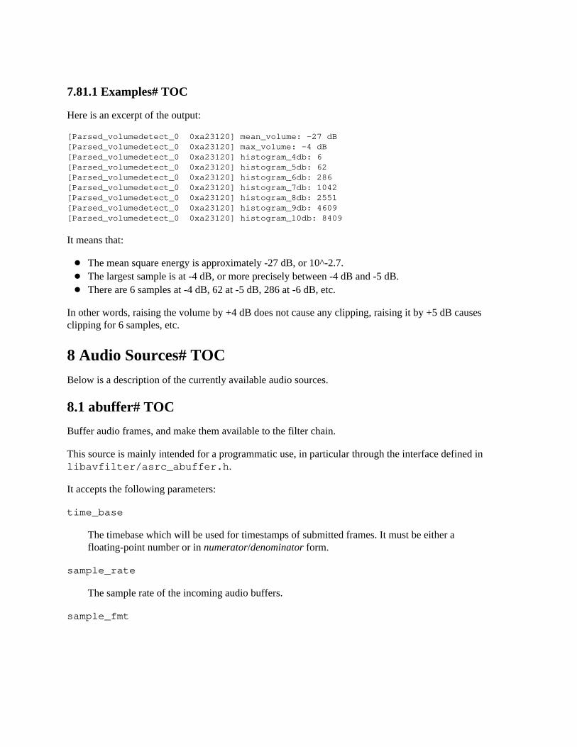
7.81.1 Examples# TOC
Here is an excerpt of the output:
[Parsed_volumedetect_0 0xa23120] mean_volume: -27 dB[Parsed_volumedetect_0 0xa23120] max_volume: -4 dB[Parsed_volumedetect_0 0xa23120] histogram_4db: 6[Parsed_volumedetect_0 0xa23120] histogram_5db: 62[Parsed_volumedetect_0 0xa23120] histogram_6db: 286[Parsed_volumedetect_0 0xa23120] histogram_7db: 1042[Parsed_volumedetect_0 0xa23120] histogram_8db: 2551[Parsed_volumedetect_0 0xa23120] histogram_9db: 4609[Parsed_volumedetect_0 0xa23120] histogram_10db: 8409
It means that:
The mean square energy is approximately -27 dB, or 10^-2.7.The largest sample is at -4 dB, or more precisely between -4 dB and -5 dB.There are 6 samples at -4 dB, 62 at -5 dB, 286 at -6 dB, etc.
In other words, raising the volume by +4 dB does not cause any clipping, raising it by +5 dB causesclipping for 6 samples, etc.
8 Audio Sources# TOCBelow is a description of the currently available audio sources.
8.1 abuffer# TOC
Buffer audio frames, and make them available to the filter chain.
This source is mainly intended for a programmatic use, in particular through the interface defined in libavfilter/asrc_abuffer.h.
It accepts the following parameters:
time_base
The timebase which will be used for timestamps of submitted frames. It must be either afloating-point number or in numerator/denominator form.
sample_rate
The sample rate of the incoming audio buffers.
sample_fmt
The sample format of the incoming audio buffers. Either a sample format name or its correspondinginteger representation from the enum AVSampleFormat in libavutil/samplefmt.h
channel_layout
The channel layout of the incoming audio buffers. Either a channel layout name fromchannel_layout_map in libavutil/channel_layout.c or its corresponding integerrepresentation from the AV_CH_LAYOUT_* macros in libavutil/channel_layout.h
channels
The number of channels of the incoming audio buffers. If both channels and channel_layout arespecified, then they must be consistent.
8.1.1 Examples# TOC
abuffer=sample_rate=44100:sample_fmt=s16p:channel_layout=stereo
will instruct the source to accept planar 16bit signed stereo at 44100Hz. Since the sample format withname "s16p" corresponds to the number 6 and the "stereo" channel layout corresponds to the value 0x3,this is equivalent to:
abuffer=sample_rate=44100:sample_fmt=6:channel_layout=0x3
8.2 aevalsrc# TOC
Generate an audio signal specified by an expression.
This source accepts in input one or more expressions (one for each channel), which are evaluated and usedto generate a corresponding audio signal.
This source accepts the following options:
exprs
Set the ’|’-separated expressions list for each separate channel. In case the channel_layoutoption is not specified, the selected channel layout depends on the number of provided expressions.Otherwise the last specified expression is applied to the remaining output channels.
channel_layout, c
Set the channel layout. The number of channels in the specified layout must be equal to the numberof specified expressions.
duration, d
Set the minimum duration of the sourced audio. See (ffmpeg-utils)the Time duration section in theffmpeg-utils(1) manual for the accepted syntax. Note that the resulting duration may be greater thanthe specified duration, as the generated audio is always cut at the end of a complete frame.
If not specified, or the expressed duration is negative, the audio is supposed to be generated forever.
nb_samples, n
Set the number of samples per channel per each output frame, default to 1024.
sample_rate, s
Specify the sample rate, default to 44100.
Each expression in exprs can contain the following constants:
n
number of the evaluated sample, starting from 0
t
time of the evaluated sample expressed in seconds, starting from 0
s
sample rate
8.2.1 Examples# TOC
Generate silence:
aevalsrc=0
Generate a sin signal with frequency of 440 Hz, set sample rate to 8000 Hz:
aevalsrc="sin(440*2*PI*t):s=8000"
Generate a two channels signal, specify the channel layout (Front Center + Back Center) explicitly:
aevalsrc="sin(420*2*PI*t)|cos(430*2*PI*t):c=FC|BC"
Generate white noise:
aevalsrc="-2+random(0)"
Generate an amplitude modulated signal:
aevalsrc="sin(10*2*PI*t)*sin(880*2*PI*t)"
Generate 2.5 Hz binaural beats on a 360 Hz carrier:
aevalsrc="0.1*sin(2*PI*(360-2.5/2)*t) | 0.1*sin(2*PI*(360+2.5/2)*t)"

8.3 anullsrc# TOC
The null audio source, return unprocessed audio frames. It is mainly useful as a template and to beemployed in analysis / debugging tools, or as the source for filters which ignore the input data (forexample the sox synth filter).
This source accepts the following options:
channel_layout, cl
Specifies the channel layout, and can be either an integer or a string representing a channel layout.The default value of channel_layout is "stereo".
Check the channel_layout_map definition in libavutil/channel_layout.c for the mappingbetween strings and channel layout values.
sample_rate, r
Specifies the sample rate, and defaults to 44100.
nb_samples, n
Set the number of samples per requested frames.
8.3.1 Examples# TOC
Set the sample rate to 48000 Hz and the channel layout to AV_CH_LAYOUT_MONO.
anullsrc=r=48000:cl=4
Do the same operation with a more obvious syntax:
anullsrc=r=48000:cl=mono
All the parameters need to be explicitly defined.
8.4 flite# TOC
Synthesize a voice utterance using the libflite library.
To enable compilation of this filter you need to configure FFmpeg with --enable-libflite.
Note that versions of the flite library prior to 2.0 are not thread-safe.
The filter accepts the following options:
list_voices
If set to 1, list the names of the available voices and exit immediately. Default value is 0.
nb_samples, n
Set the maximum number of samples per frame. Default value is 512.
textfile
Set the filename containing the text to speak.
text
Set the text to speak.
voice, v
Set the voice to use for the speech synthesis. Default value is kal. See also the list_voices option.
8.4.1 Examples# TOC
Read from file speech.txt, and synthesize the text using the standard flite voice:
flite=textfile=speech.txt
Read the specified text selecting the slt voice:
flite=text=’So fare thee well, poor devil of a Sub-Sub, whose commentator I am’:voice=slt
Input text to ffmpeg:
ffmpeg -f lavfi -i flite=text=’So fare thee well, poor devil of a Sub-Sub, whose commentator I am’:voice=slt
Make ffplay speak the specified text, using flite and the lavfi device:
ffplay -f lavfi flite=text=’No more be grieved for which that thou hast done.’
For more information about libflite, check: http://www.festvox.org/flite/
8.5 anoisesrc# TOC
Generate a noise audio signal.
The filter accepts the following options:
sample_rate, r
Specify the sample rate. Default value is 48000 Hz.
amplitude, a
Specify the amplitude (0.0 - 1.0) of the generated audio stream. Default value is 1.0.
duration, d
Specify the duration of the generated audio stream. Not specifying this option results in noise with aninfinite length.
color, colour, c
Specify the color of noise. Available noise colors are white, pink, brown, blue and violet. Defaultcolor is white.
seed, s
Specify a value used to seed the PRNG.
nb_samples, n
Set the number of samples per each output frame, default is 1024.
8.5.1 Examples# TOC
Generate 60 seconds of pink noise, with a 44.1 kHz sampling rate and an amplitude of 0.5:
anoisesrc=d=60:c=pink:r=44100:a=0.5
8.6 hilbert# TOC
Generate odd-tap Hilbert transform FIR coefficients.
The resulting stream can be used with afir filter for phase-shifting the signal by 90 degrees.
This is used in many matrix coding schemes and for analytic signal generation. The process is oftenwritten as a multiplication by i (or j), the imaginary unit.
The filter accepts the following options:
sample_rate, s
Set sample rate, default is 44100.
taps, t
Set length of FIR filter, default is 22051.
nb_samples, n
Set number of samples per each frame.
win_func, w
Set window function to be used when generating FIR coefficients.
8.7 sine# TOC
Generate an audio signal made of a sine wave with amplitude 1/8.
The audio signal is bit-exact.
The filter accepts the following options:
frequency, f
Set the carrier frequency. Default is 440 Hz.
beep_factor, b
Enable a periodic beep every second with frequency beep_factor times the carrier frequency. Defaultis 0, meaning the beep is disabled.
sample_rate, r
Specify the sample rate, default is 44100.
duration, d
Specify the duration of the generated audio stream.
samples_per_frame
Set the number of samples per output frame.
The expression can contain the following constants:
n
The (sequential) number of the output audio frame, starting from 0.
pts
The PTS (Presentation TimeStamp) of the output audio frame, expressed in TB units.
t
The PTS of the output audio frame, expressed in seconds.

TB
The timebase of the output audio frames.
Default is 1024.
8.7.1 Examples# TOC
Generate a simple 440 Hz sine wave:
sine
Generate a 220 Hz sine wave with a 880 Hz beep each second, for 5 seconds:
sine=220:4:d=5sine=f=220:b=4:d=5sine=frequency=220:beep_factor=4:duration=5
Generate a 1 kHz sine wave following 1602,1601,1602,1601,1602 NTSC pattern:
sine=1000:samples_per_frame=’st(0,mod(n,5)); 1602-not(not(eq(ld(0),1)+eq(ld(0),3)))’
9 Audio Sinks# TOCBelow is a description of the currently available audio sinks.
9.1 abuffersink# TOC
Buffer audio frames, and make them available to the end of filter chain.
This sink is mainly intended for programmatic use, in particular through the interface defined in libavfilter/buffersink.h or the options system.
It accepts a pointer to an AVABufferSinkContext structure, which defines the incoming buffers’ formats,to be passed as the opaque parameter to avfilter_init_filter for initialization.
9.2 anullsink# TOC
Null audio sink; do absolutely nothing with the input audio. It is mainly useful as a template and for use inanalysis / debugging tools.
10 Video Filters# TOCWhen you configure your FFmpeg build, you can disable any of the existing filters using --disable-filters. The configure output will show the video filters included in your build.
Below is a description of the currently available video filters.
10.1 alphaextract# TOC
Extract the alpha component from the input as a grayscale video. This is especially useful with the alphamerge filter.
10.2 alphamerge# TOC
Add or replace the alpha component of the primary input with the grayscale value of a second input. Thisis intended for use with alphaextract to allow the transmission or storage of frame sequences that havealpha in a format that doesn’t support an alpha channel.
For example, to reconstruct full frames from a normal YUV-encoded video and a separate video createdwith alphaextract, you might use:
movie=in_alpha.mkv [alpha]; [in][alpha] alphamerge [out]
Since this filter is designed for reconstruction, it operates on frame sequences without consideringtimestamps, and terminates when either input reaches end of stream. This will cause problems if yourencoding pipeline drops frames. If you’re trying to apply an image as an overlay to a video stream,consider the overlay filter instead.
10.3 ass# TOC
Same as the subtitles filter, except that it doesn’t require libavcodec and libavformat to work. On the otherhand, it is limited to ASS (Advanced Substation Alpha) subtitles files.
This filter accepts the following option in addition to the common options from the subtitles filter:
shaping
Set the shaping engine
Available values are:
‘auto’
The default libass shaping engine, which is the best available.
‘simple’
Fast, font-agnostic shaper that can do only substitutions
‘complex’
Slower shaper using OpenType for substitutions and positioning
The default is auto.
10.4 atadenoise# TOC
Apply an Adaptive Temporal Averaging Denoiser to the video input.
The filter accepts the following options:
0a
Set threshold A for 1st plane. Default is 0.02. Valid range is 0 to 0.3.
0b
Set threshold B for 1st plane. Default is 0.04. Valid range is 0 to 5.
1a
Set threshold A for 2nd plane. Default is 0.02. Valid range is 0 to 0.3.
1b
Set threshold B for 2nd plane. Default is 0.04. Valid range is 0 to 5.
2a
Set threshold A for 3rd plane. Default is 0.02. Valid range is 0 to 0.3.
2b
Set threshold B for 3rd plane. Default is 0.04. Valid range is 0 to 5.
Threshold A is designed to react on abrupt changes in the input signal and threshold B is designed toreact on continuous changes in the input signal.
s
Set number of frames filter will use for averaging. Default is 33. Must be odd number in range [5, 129].
p
Set what planes of frame filter will use for averaging. Default is all.
10.5 avgblur# TOC
Apply average blur filter.
The filter accepts the following options:
sizeX
Set horizontal kernel size.
planes
Set which planes to filter. By default all planes are filtered.
sizeY
Set vertical kernel size, if zero it will be same as sizeX. Default is 0.
10.6 bbox# TOC
Compute the bounding box for the non-black pixels in the input frame luminance plane.
This filter computes the bounding box containing all the pixels with a luminance value greater than theminimum allowed value. The parameters describing the bounding box are printed on the filter log.
The filter accepts the following option:
min_val
Set the minimal luminance value. Default is 16.
10.7 bitplanenoise# TOC
Show and measure bit plane noise.
The filter accepts the following options:
bitplane
Set which plane to analyze. Default is 1.
filter
Filter out noisy pixels from bitplane set above. Default is disabled.
10.8 blackdetect# TOC
Detect video intervals that are (almost) completely black. Can be useful to detect chapter transitions,commercials, or invalid recordings. Output lines contains the time for the start, end and duration of thedetected black interval expressed in seconds.
In order to display the output lines, you need to set the loglevel at least to the AV_LOG_INFO value.
The filter accepts the following options:
black_min_duration, d
Set the minimum detected black duration expressed in seconds. It must be a non-negative floatingpoint number.
Default value is 2.0.
picture_black_ratio_th, pic_th
Set the threshold for considering a picture "black". Express the minimum value for the ratio:
nb_black_pixels / nb_pixels
for which a picture is considered black. Default value is 0.98.
pixel_black_th, pix_th
Set the threshold for considering a pixel "black".
The threshold expresses the maximum pixel luminance value for which a pixel is considered "black".The provided value is scaled according to the following equation:
absolute_threshold = luminance_minimum_value + pixel_black_th * luminance_range_size
luminance_range_size and luminance_minimum_value depend on the input video format, the range is[0-255] for YUV full-range formats and [16-235] for YUV non full-range formats.
Default value is 0.10.
The following example sets the maximum pixel threshold to the minimum value, and detects only blackintervals of 2 or more seconds:
blackdetect=d=2:pix_th=0.00
10.9 blackframe# TOC
Detect frames that are (almost) completely black. Can be useful to detect chapter transitions orcommercials. Output lines consist of the frame number of the detected frame, the percentage of blackness,the position in the file if known or -1 and the timestamp in seconds.
In order to display the output lines, you need to set the loglevel at least to the AV_LOG_INFO value.
This filter exports frame metadata lavfi.blackframe.pblack. The value represents the percentageof pixels in the picture that are below the threshold value.
It accepts the following parameters:
amount
The percentage of the pixels that have to be below the threshold; it defaults to 98.
threshold, thresh
The threshold below which a pixel value is considered black; it defaults to 32.
10.10 blend, tblend# TOC
Blend two video frames into each other.
The blend filter takes two input streams and outputs one stream, the first input is the "top" layer andsecond input is "bottom" layer. By default, the output terminates when the longest input terminates.
The tblend (time blend) filter takes two consecutive frames from one single stream, and outputs theresult obtained by blending the new frame on top of the old frame.
A description of the accepted options follows.
c0_mode c1_mode c2_mode c3_mode all_mode
Set blend mode for specific pixel component or all pixel components in case of all_mode. Defaultvalue is normal.
Available values for component modes are:
‘addition’ ‘grainmerge’ ‘and’ ‘average’ ‘burn’ ‘darken’ ‘difference’ ‘grainextract’ ‘divide’
‘dodge’ ‘freeze’ ‘exclusion’ ‘extremity’ ‘glow’ ‘hardlight’ ‘hardmix’ ‘heat’ ‘lighten’ ‘linearlight’ ‘multiply’ ‘multiply128’ ‘negation’ ‘normal’ ‘or’ ‘overlay’ ‘phoenix’ ‘pinlight’ ‘reflect’ ‘screen’ ‘softlight’ ‘subtract’ ‘vividlight’ ‘xor’
c0_opacity c1_opacity c2_opacity c3_opacity all_opacity
Set blend opacity for specific pixel component or all pixel components in case of all_opacity. Onlyused in combination with pixel component blend modes.
c0_expr c1_expr c2_expr c3_expr all_expr
Set blend expression for specific pixel component or all pixel components in case of all_expr. Notethat related mode options will be ignored if those are set.
The expressions can use the following variables:
N
The sequential number of the filtered frame, starting from 0.
X Y
the coordinates of the current sample
W H
the width and height of currently filtered plane
SW SH
Width and height scale depending on the currently filtered plane. It is the ratio between thecorresponding luma plane number of pixels and the current plane ones. E.g. for YUV4:2:0 thevalues are 1,1 for the luma plane, and 0.5,0.5 for chroma planes.
T
Time of the current frame, expressed in seconds.
TOP, A
Value of pixel component at current location for first video frame (top layer).
BOTTOM, B
Value of pixel component at current location for second video frame (bottom layer).
The blend filter also supports the framesync options.
10.10.1 Examples# TOC
Apply transition from bottom layer to top layer in first 10 seconds:
blend=all_expr=’A*(if(gte(T,10),1,T/10))+B*(1-(if(gte(T,10),1,T/10)))’
Apply linear horizontal transition from top layer to bottom layer:
blend=all_expr=’A*(X/W)+B*(1-X/W)’
Apply 1x1 checkerboard effect:
blend=all_expr=’if(eq(mod(X,2),mod(Y,2)),A,B)’
Apply uncover left effect:

blend=all_expr=’if(gte(N*SW+X,W),A,B)’
Apply uncover down effect:
blend=all_expr=’if(gte(Y-N*SH,0),A,B)’
Apply uncover up-left effect:
blend=all_expr=’if(gte(T*SH*40+Y,H)*gte((T*40*SW+X)*W/H,W),A,B)’
Split diagonally video and shows top and bottom layer on each side:
blend=all_expr=’if(gt(X,Y*(W/H)),A,B)’
Display differences between the current and the previous frame:
tblend=all_mode=grainextract
10.11 boxblur# TOC
Apply a boxblur algorithm to the input video.
It accepts the following parameters:
luma_radius, lr luma_power, lp chroma_radius, cr chroma_power, cp alpha_radius, ar alpha_power, ap
A description of the accepted options follows.
luma_radius, lr chroma_radius, cr alpha_radius, ar
Set an expression for the box radius in pixels used for blurring the corresponding input plane.
The radius value must be a non-negative number, and must not be greater than the value of theexpression min(w,h)/2 for the luma and alpha planes, and of min(cw,ch)/2 for the chroma planes.
Default value for luma_radius is "2". If not specified, chroma_radius and alpha_radiusdefault to the corresponding value set for luma_radius.
The expressions can contain the following constants:
w
h
The input width and height in pixels.
cw ch
The input chroma image width and height in pixels.
hsub vsub
The horizontal and vertical chroma subsample values. For example, for the pixel format"yuv422p", hsub is 2 and vsub is 1.
luma_power, lp chroma_power, cp alpha_power, ap
Specify how many times the boxblur filter is applied to the corresponding plane.
Default value for luma_power is 2. If not specified, chroma_power and alpha_power defaultto the corresponding value set for luma_power.
A value of 0 will disable the effect.
10.11.1 Examples# TOC
Apply a boxblur filter with the luma, chroma, and alpha radii set to 2:
boxblur=luma_radius=2:luma_power=1boxblur=2:1
Set the luma radius to 2, and alpha and chroma radius to 0:
boxblur=2:1:cr=0:ar=0
Set the luma and chroma radii to a fraction of the video dimension:
boxblur=luma_radius=min(h\,w)/10:luma_power=1:chroma_radius=min(cw\,ch)/10:chroma_power=1
10.12 bwdif# TOC
Deinterlace the input video ("bwdif" stands for "Bob Weaver Deinterlacing Filter").
Motion adaptive deinterlacing based on yadif with the use of w3fdif and cubic interpolation algorithms. Itaccepts the following parameters:
mode
The interlacing mode to adopt. It accepts one of the following values:
0, send_frame
Output one frame for each frame.
1, send_field
Output one frame for each field.
The default value is send_field.
parity
The picture field parity assumed for the input interlaced video. It accepts one of the following values:
0, tff
Assume the top field is first.
1, bff
Assume the bottom field is first.
-1, auto
Enable automatic detection of field parity.
The default value is auto. If the interlacing is unknown or the decoder does not export thisinformation, top field first will be assumed.
deint
Specify which frames to deinterlace. Accept one of the following values:
0, all
Deinterlace all frames.
1, interlaced
Only deinterlace frames marked as interlaced.
The default value is all.
10.13 chromakey# TOC
YUV colorspace color/chroma keying.
The filter accepts the following options:
color
The color which will be replaced with transparency.
similarity
Similarity percentage with the key color.
0.01 matches only the exact key color, while 1.0 matches everything.
blend
Blend percentage.
0.0 makes pixels either fully transparent, or not transparent at all.
Higher values result in semi-transparent pixels, with a higher transparency the more similar the pixelscolor is to the key color.
yuv
Signals that the color passed is already in YUV instead of RGB.
Literal colors like "green" or "red" don’t make sense with this enabled anymore. This can be used topass exact YUV values as hexadecimal numbers.
10.13.1 Examples# TOC
Make every green pixel in the input image transparent:
ffmpeg -i input.png -vf chromakey=green out.png
Overlay a greenscreen-video on top of a static black background.
ffmpeg -f lavfi -i color=c=black:s=1280x720 -i video.mp4 -shortest -filter_complex "[1:v]chromakey=0x70de77:0.1:0.2[ckout];[0:v][ckout]overlay[out]" -map "[out]" output.mkv
10.14 ciescope# TOC
Display CIE color diagram with pixels overlaid onto it.
The filter accepts the following options:
system
Set color system.
‘ntsc, 470m’ ‘ebu, 470bg’ ‘smpte’ ‘240m’ ‘apple’ ‘widergb’ ‘cie1931’ ‘rec709, hdtv’ ‘uhdtv, rec2020’
cie
Set CIE system.
‘xyy’ ‘ucs’ ‘luv’
gamuts
Set what gamuts to draw.
See system option for available values.
size, s
Set ciescope size, by default set to 512.
intensity, i
Set intensity used to map input pixel values to CIE diagram.
contrast
Set contrast used to draw tongue colors that are out of active color system gamut.
corrgamma
Correct gamma displayed on scope, by default enabled.
showwhite
Show white point on CIE diagram, by default disabled.
gamma
Set input gamma. Used only with XYZ input color space.
10.15 codecview# TOC
Visualize information exported by some codecs.
Some codecs can export information through frames using side-data or other means. For example, someMPEG based codecs export motion vectors through the export_mvs flag in the codec flags2 option.
The filter accepts the following option:
mv
Set motion vectors to visualize.
Available flags for mv are:
‘pf’
forward predicted MVs of P-frames
‘bf’
forward predicted MVs of B-frames
‘bb’
backward predicted MVs of B-frames
qp
Display quantization parameters using the chroma planes.
mv_type, mvt
Set motion vectors type to visualize. Includes MVs from all frames unless specified by frame_type option.
Available flags for mv_type are:
‘fp’
forward predicted MVs
‘bp’
backward predicted MVs
frame_type, ft
Set frame type to visualize motion vectors of.
Available flags for frame_type are:
‘if’
intra-coded frames (I-frames)
‘pf’
predicted frames (P-frames)
‘bf’
bi-directionally predicted frames (B-frames)
10.15.1 Examples# TOC
Visualize forward predicted MVs of all frames using ffplay:
ffplay -flags2 +export_mvs input.mp4 -vf codecview=mv_type=fp
Visualize multi-directionals MVs of P and B-Frames using ffplay:
ffplay -flags2 +export_mvs input.mp4 -vf codecview=mv=pf+bf+bb
10.16 colorbalance# TOC
Modify intensity of primary colors (red, green and blue) of input frames.
The filter allows an input frame to be adjusted in the shadows, midtones or highlights regions for thered-cyan, green-magenta or blue-yellow balance.
A positive adjustment value shifts the balance towards the primary color, a negative value towards thecomplementary color.
The filter accepts the following options:
rs gs bs
Adjust red, green and blue shadows (darkest pixels).
rm gm

bm
Adjust red, green and blue midtones (medium pixels).
rh gh bh
Adjust red, green and blue highlights (brightest pixels).
Allowed ranges for options are [-1.0, 1.0]. Defaults are 0.
10.16.1 Examples# TOC
Add red color cast to shadows:
colorbalance=rs=.3
10.17 colorkey# TOC
RGB colorspace color keying.
The filter accepts the following options:
color
The color which will be replaced with transparency.
similarity
Similarity percentage with the key color.
0.01 matches only the exact key color, while 1.0 matches everything.
blend
Blend percentage.
0.0 makes pixels either fully transparent, or not transparent at all.
Higher values result in semi-transparent pixels, with a higher transparency the more similar the pixelscolor is to the key color.
10.17.1 Examples# TOC
Make every green pixel in the input image transparent:
ffmpeg -i input.png -vf colorkey=green out.png
Overlay a greenscreen-video on top of a static background image.
ffmpeg -i background.png -i video.mp4 -filter_complex "[1:v]colorkey=0x3BBD1E:0.3:0.2[ckout];[0:v][ckout]overlay[out]" -map "[out]" output.flv
10.18 colorlevels# TOC
Adjust video input frames using levels.
The filter accepts the following options:
rimin gimin bimin aimin
Adjust red, green, blue and alpha input black point. Allowed ranges for options are [-1.0, 1.0].Defaults are 0.
rimax gimax bimax aimax
Adjust red, green, blue and alpha input white point. Allowed ranges for options are [-1.0, 1.0].Defaults are 1.
Input levels are used to lighten highlights (bright tones), darken shadows (dark tones), change thebalance of bright and dark tones.
romin gomin bomin aomin
Adjust red, green, blue and alpha output black point. Allowed ranges for options are [0, 1.0].Defaults are 0.
romax gomax bomax aomax
Adjust red, green, blue and alpha output white point. Allowed ranges for options are [0, 1.0].Defaults are 1.
Output levels allows manual selection of a constrained output level range.
10.18.1 Examples# TOC
Make video output darker:
colorlevels=rimin=0.058:gimin=0.058:bimin=0.058
Increase contrast:
colorlevels=rimin=0.039:gimin=0.039:bimin=0.039:rimax=0.96:gimax=0.96:bimax=0.96
Make video output lighter:
colorlevels=rimax=0.902:gimax=0.902:bimax=0.902
Increase brightness:
colorlevels=romin=0.5:gomin=0.5:bomin=0.5
10.19 colorchannelmixer# TOC
Adjust video input frames by re-mixing color channels.
This filter modifies a color channel by adding the values associated to the other channels of the samepixels. For example if the value to modify is red, the output value will be:
red=red*rr + blue*rb + green*rg + alpha*ra
The filter accepts the following options:
rr rg rb ra
Adjust contribution of input red, green, blue and alpha channels for output red channel. Default is 1for rr , and 0 for rg, rb and ra.
gr gg gb ga
Adjust contribution of input red, green, blue and alpha channels for output green channel. Default is 1 for gg, and 0 for gr, gb and ga.
br bg
bb ba
Adjust contribution of input red, green, blue and alpha channels for output blue channel. Default is 1for bb, and 0 for br, bg and ba.
ar ag ab aa
Adjust contribution of input red, green, blue and alpha channels for output alpha channel. Default is 1for aa, and 0 for ar, ag and ab.
Allowed ranges for options are [-2.0, 2.0].
10.19.1 Examples# TOC
Convert source to grayscale:
colorchannelmixer=.3:.4:.3:0:.3:.4:.3:0:.3:.4:.3
Simulate sepia tones:
colorchannelmixer=.393:.769:.189:0:.349:.686:.168:0:.272:.534:.131
10.20 colormatrix# TOC
Convert color matrix.
The filter accepts the following options:
src dst
Specify the source and destination color matrix. Both values must be specified.
The accepted values are:
‘bt709’
BT.709
‘fcc’
FCC
‘bt601’
BT.601
‘bt470’
BT.470
‘bt470bg’
BT.470BG
‘smpte170m’
SMPTE-170M
‘smpte240m’
SMPTE-240M
‘bt2020’
BT.2020
For example to convert from BT.601 to SMPTE-240M, use the command:
colormatrix=bt601:smpte240m
10.21 colorspace# TOC
Convert colorspace, transfer characteristics or color primaries. Input video needs to have an even size.
The filter accepts the following options:
all
Specify all color properties at once.
The accepted values are:
‘bt470m’
BT.470M
‘bt470bg’
BT.470BG
‘bt601-6-525’
BT.601-6 525
‘bt601-6-625’
BT.601-6 625
‘bt709’
BT.709
‘smpte170m’
SMPTE-170M
‘smpte240m’
SMPTE-240M
‘bt2020’
BT.2020
space
Specify output colorspace.
The accepted values are:
‘bt709’
BT.709
‘fcc’
FCC
‘bt470bg’
BT.470BG or BT.601-6 625
‘smpte170m’
SMPTE-170M or BT.601-6 525
‘smpte240m’
SMPTE-240M
‘ycgco’
YCgCo
‘bt2020ncl’
BT.2020 with non-constant luminance
trc
Specify output transfer characteristics.
The accepted values are:
‘bt709’
BT.709
‘bt470m’
BT.470M
‘bt470bg’
BT.470BG
‘gamma22’
Constant gamma of 2.2
‘gamma28’
Constant gamma of 2.8
‘smpte170m’
SMPTE-170M, BT.601-6 625 or BT.601-6 525
‘smpte240m’
SMPTE-240M
‘srgb’
SRGB
‘iec61966-2-1’
iec61966-2-1
‘iec61966-2-4’
iec61966-2-4
‘xvycc’
xvycc
‘bt2020-10’
BT.2020 for 10-bits content
‘bt2020-12’
BT.2020 for 12-bits content
primaries
Specify output color primaries.
The accepted values are:
‘bt709’
BT.709
‘bt470m’
BT.470M
‘bt470bg’
BT.470BG or BT.601-6 625
‘smpte170m’
SMPTE-170M or BT.601-6 525
‘smpte240m’
SMPTE-240M
‘film’
film
‘smpte431’
SMPTE-431
‘smpte432’
SMPTE-432
‘bt2020’
BT.2020
‘jedec-p22’
JEDEC P22 phosphors
range
Specify output color range.
The accepted values are:
‘tv’
TV (restricted) range
‘mpeg’
MPEG (restricted) range
‘pc’
PC (full) range
‘jpeg’
JPEG (full) range
format
Specify output color format.
The accepted values are:
‘yuv420p’
YUV 4:2:0 planar 8-bits
‘yuv420p10’
YUV 4:2:0 planar 10-bits
‘yuv420p12’
YUV 4:2:0 planar 12-bits
‘yuv422p’
YUV 4:2:2 planar 8-bits
‘yuv422p10’
YUV 4:2:2 planar 10-bits
‘yuv422p12’
YUV 4:2:2 planar 12-bits
‘yuv444p’
YUV 4:4:4 planar 8-bits
‘yuv444p10’
YUV 4:4:4 planar 10-bits
‘yuv444p12’
YUV 4:4:4 planar 12-bits
fast
Do a fast conversion, which skips gamma/primary correction. This will take significantly less CPU,but will be mathematically incorrect. To get output compatible with that produced by the colormatrixfilter, use fast=1.
dither
Specify dithering mode.
The accepted values are:
‘none’
No dithering
‘fsb’
Floyd-Steinberg dithering
wpadapt
Whitepoint adaptation mode.
The accepted values are:
‘bradford’
Bradford whitepoint adaptation
‘vonkries’
von Kries whitepoint adaptation
‘identity’
identity whitepoint adaptation (i.e. no whitepoint adaptation)
iall
Override all input properties at once. Same accepted values as all.
ispace
Override input colorspace. Same accepted values as space.
iprimaries
Override input color primaries. Same accepted values as primaries.
itrc
Override input transfer characteristics. Same accepted values as trc.
irange
Override input color range. Same accepted values as range.
The filter converts the transfer characteristics, color space and color primaries to the specified user values.The output value, if not specified, is set to a default value based on the "all" property. If that property isalso not specified, the filter will log an error. The output color range and format default to the same valueas the input color range and format. The input transfer characteristics, color space, color primaries andcolor range should be set on the input data. If any of these are missing, the filter will log an error and noconversion will take place.
For example to convert the input to SMPTE-240M, use the command:
colorspace=smpte240m
10.22 convolution# TOC
Apply convolution 3x3, 5x5 or 7x7 filter.
The filter accepts the following options:
0m 1m 2m 3m
Set matrix for each plane. Matrix is sequence of 9, 25 or 49 signed integers.
0rdiv 1rdiv 2rdiv 3rdiv
Set multiplier for calculated value for each plane.
0bias 1bias 2bias 3bias
Set bias for each plane. This value is added to the result of the multiplication. Useful for making theoverall image brighter or darker. Default is 0.0.
10.22.1 Examples# TOC
Apply sharpen:
convolution="0 -1 0 -1 5 -1 0 -1 0:0 -1 0 -1 5 -1 0 -1 0:0 -1 0 -1 5 -1 0 -1 0:0 -1 0 -1 5 -1 0 -1 0"
Apply blur:
convolution="1 1 1 1 1 1 1 1 1:1 1 1 1 1 1 1 1 1:1 1 1 1 1 1 1 1 1:1 1 1 1 1 1 1 1 1:1/9:1/9:1/9:1/9"
Apply edge enhance:
convolution="0 0 0 -1 1 0 0 0 0:0 0 0 -1 1 0 0 0 0:0 0 0 -1 1 0 0 0 0:0 0 0 -1 1 0 0 0 0:5:1:1:1:0:128:128:128"
Apply edge detect:
convolution="0 1 0 1 -4 1 0 1 0:0 1 0 1 -4 1 0 1 0:0 1 0 1 -4 1 0 1 0:0 1 0 1 -4 1 0 1 0:5:5:5:1:0:128:128:128"
Apply laplacian edge detector which includes diagonals:
convolution="1 1 1 1 -8 1 1 1 1:1 1 1 1 -8 1 1 1 1:1 1 1 1 -8 1 1 1 1:1 1 1 1 -8 1 1 1 1:5:5:5:1:0:128:128:0"
Apply emboss:
convolution="-2 -1 0 -1 1 1 0 1 2:-2 -1 0 -1 1 1 0 1 2:-2 -1 0 -1 1 1 0 1 2:-2 -1 0 -1 1 1 0 1 2"
10.23 convolve# TOC
Apply 2D convolution of video stream in frequency domain using second stream as impulse.
The filter accepts the following options:
planes
Set which planes to process.
impulse
Set which impulse video frames will be processed, can be first or all. Default is all.
The convolve filter also supports the framesync options.
10.24 copy# TOC
Copy the input video source unchanged to the output. This is mainly useful for testing purposes.
10.25 coreimage# TOC
Video filtering on GPU using Apple’s CoreImage API on OSX.
Hardware acceleration is based on an OpenGL context. Usually, this means it is processed by videohardware. However, software-based OpenGL implementations exist which means there is no guarantee forhardware processing. It depends on the respective OSX.
There are many filters and image generators provided by Apple that come with a large variety of options.The filter has to be referenced by its name along with its options.
The coreimage filter accepts the following options:
list_filters
List all available filters and generators along with all their respective options as well as possibleminimum and maximum values along with the default values.
list_filters=true
filter
Specify all filters by their respective name and options. Use list_filters to determine all valid filternames and options. Numerical options are specified by a float value and are automatically clamped totheir respective value range. Vector and color options have to be specified by a list of space separatedfloat values. Character escaping has to be done. A special option name default is available to usedefault options for a filter.
It is required to specify either default or at least one of the filter options. All omitted options areused with their default values. The syntax of the filter string is as follows:
filter=<NAME>@<OPTION>=<VALUE>[@<OPTION>=<VALUE>][@...][#<NAME>@<OPTION>=<VALUE>[@<OPTION>=<VALUE>][@...]][#...]
output_rect
Specify a rectangle where the output of the filter chain is copied into the input image. It is given by alist of space separated float values:
output_rect=x\ y\ width\ height
If not given, the output rectangle equals the dimensions of the input image. The output rectangle isautomatically cropped at the borders of the input image. Negative values are valid for each component.
output_rect=25\ 25\ 100\ 100
Several filters can be chained for successive processing without GPU-HOST transfers allowing for fastprocessing of complex filter chains. Currently, only filters with zero (generators) or exactly one (filters)input image and one output image are supported. Also, transition filters are not yet usable as intended.
Some filters generate output images with additional padding depending on the respective filter kernel. Thepadding is automatically removed to ensure the filter output has the same size as the input image.
For image generators, the size of the output image is determined by the previous output image of the filterchain or the input image of the whole filterchain, respectively. The generators do not use the pixelinformation of this image to generate their output. However, the generated output is blended onto thisimage, resulting in partial or complete coverage of the output image.
The coreimagesrc video source can be used for generating input images which are directly fed into thefilter chain. By using it, providing input images by another video source or an input video is not required.
10.25.1 Examples# TOC
List all filters available:
coreimage=list_filters=true
Use the CIBoxBlur filter with default options to blur an image:
coreimage=filter=CIBoxBlur@default
Use a filter chain with CISepiaTone at default values and CIVignetteEffect with its center at 100x100and a radius of 50 pixels:
coreimage=filter=CIBoxBlur@default#CIVignetteEffect@inputCenter=100\ 100@inputRadius=50
Use nullsrc and CIQRCodeGenerator to create a QR code for the FFmpeg homepage, given ascomplete and escaped command-line for Apple’s standard bash shell:
ffmpeg -f lavfi -i nullsrc=s=100x100,coreimage=filter=CIQRCodeGenerator@inputMessage=https\\\\\://FFmpeg.org/@inputCorrectionLevel=H -frames:v 1 QRCode.png
10.26 crop# TOC
Crop the input video to given dimensions.
It accepts the following parameters:
w, out_w
The width of the output video. It defaults to iw. This expression is evaluated only once during thefilter configuration, or when the ‘w’ or ‘out_w’ command is sent.
h, out_h
The height of the output video. It defaults to ih. This expression is evaluated only once during thefilter configuration, or when the ‘h’ or ‘out_h’ command is sent.
x
The horizontal position, in the input video, of the left edge of the output video. It defaults to (in_w-out_w)/2. This expression is evaluated per-frame.
y
The vertical position, in the input video, of the top edge of the output video. It defaults to (in_h-out_h)/2. This expression is evaluated per-frame.
keep_aspect
If set to 1 will force the output display aspect ratio to be the same of the input, by changing the outputsample aspect ratio. It defaults to 0.
exact
Enable exact cropping. If enabled, subsampled videos will be cropped at exact width/height/x/y asspecified and will not be rounded to nearest smaller value. It defaults to 0.
The out_w, out_h, x, y parameters are expressions containing the following constants:
x y
The computed values for x and y. They are evaluated for each new frame.
in_w in_h
The input width and height.
iw ih
These are the same as in_w and in_h.
out_w out_h
The output (cropped) width and height.
ow oh
These are the same as out_w and out_h.
a
same as iw / ih
sar
input sample aspect ratio
dar
input display aspect ratio, it is the same as (iw / ih) * sar
hsub vsub
horizontal and vertical chroma subsample values. For example for the pixel format "yuv422p" hsub is2 and vsub is 1.
n
The number of the input frame, starting from 0.
pos
the position in the file of the input frame, NAN if unknown
t
The timestamp expressed in seconds. It’s NAN if the input timestamp is unknown.
The expression for out_w may depend on the value of out_h, and the expression for out_h may depend on out_w, but they cannot depend on x and y, as x and y are evaluated after out_w and out_h.
The x and y parameters specify the expressions for the position of the top-left corner of the output(non-cropped) area. They are evaluated for each frame. If the evaluated value is not valid, it isapproximated to the nearest valid value.
The expression for x may depend on y, and the expression for y may depend on x.
10.26.1 Examples# TOC
Crop area with size 100x100 at position (12,34).
crop=100:100:12:34
Using named options, the example above becomes:
crop=w=100:h=100:x=12:y=34
Crop the central input area with size 100x100:
crop=100:100
Crop the central input area with size 2/3 of the input video:
crop=2/3*in_w:2/3*in_h
Crop the input video central square:
crop=out_w=in_hcrop=in_h
Delimit the rectangle with the top-left corner placed at position 100:100 and the right-bottom cornercorresponding to the right-bottom corner of the input image.
crop=in_w-100:in_h-100:100:100
Crop 10 pixels from the left and right borders, and 20 pixels from the top and bottom borders
crop=in_w-2*10:in_h-2*20
Keep only the bottom right quarter of the input image:
crop=in_w/2:in_h/2:in_w/2:in_h/2
Crop height for getting Greek harmony:
crop=in_w:1/PHI*in_w
Apply trembling effect:
crop=in_w/2:in_h/2:(in_w-out_w)/2+((in_w-out_w)/2)*sin(n/10):(in_h-out_h)/2 +((in_h-out_h)/2)*sin(n/7)
Apply erratic camera effect depending on timestamp:
crop=in_w/2:in_h/2:(in_w-out_w)/2+((in_w-out_w)/2)*sin(t*10):(in_h-out_h)/2 +((in_h-out_h)/2)*sin(t*13)"
Set x depending on the value of y:
crop=in_w/2:in_h/2:y:10+10*sin(n/10)
10.26.2 Commands# TOC
This filter supports the following commands:
w, out_w h, out_h x y
Set width/height of the output video and the horizontal/vertical position in the input video. Thecommand accepts the same syntax of the corresponding option.
If the specified expression is not valid, it is kept at its current value.
10.27 cropdetect# TOC
Auto-detect the crop size.
It calculates the necessary cropping parameters and prints the recommended parameters via the loggingsystem. The detected dimensions correspond to the non-black area of the input video.
It accepts the following parameters:
limit
Set higher black value threshold, which can be optionally specified from nothing (0) to everything(255 for 8-bit based formats). An intensity value greater to the set value is considered non-black. Itdefaults to 24. You can also specify a value between 0.0 and 1.0 which will be scaled depending onthe bitdepth of the pixel format.
round
The value which the width/height should be divisible by. It defaults to 16. The offset is automaticallyadjusted to center the video. Use 2 to get only even dimensions (needed for 4:2:2 video). 16 is bestwhen encoding to most video codecs.
reset_count, reset
Set the counter that determines after how many frames cropdetect will reset the previously detectedlargest video area and start over to detect the current optimal crop area. Default value is 0.
This can be useful when channel logos distort the video area. 0 indicates ’never reset’, and returns thelargest area encountered during playback.
10.28 curves# TOC
Apply color adjustments using curves.
This filter is similar to the Adobe Photoshop and GIMP curves tools. Each component (red, green andblue) has its values defined by N key points tied from each other using a smooth curve. The x-axisrepresents the pixel values from the input frame, and the y-axis the new pixel values to be set for theoutput frame.
By default, a component curve is defined by the two points (0;0) and (1;1). This creates a straight linewhere each original pixel value is "adjusted" to its own value, which means no change to the image.
The filter allows you to redefine these two points and add some more. A new curve (using a natural cubicspline interpolation) will be define to pass smoothly through all these new coordinates. The new definedpoints needs to be strictly increasing over the x-axis, and their x and y values must be in the [0;1] interval.If the computed curves happened to go outside the vector spaces, the values will be clipped accordingly.
The filter accepts the following options:
preset
Select one of the available color presets. This option can be used in addition to the r, g, bparameters; in this case, the later options takes priority on the preset values. Available presets are:
‘none’ ‘color_negative’ ‘cross_process’ ‘darker’ ‘increase_contrast’ ‘lighter’ ‘linear_contrast’ ‘medium_contrast’ ‘negative’ ‘strong_contrast’ ‘vintage’
Default is none.
master, m
Set the master key points. These points will define a second pass mapping. It is sometimes called a"luminance" or "value" mapping. It can be used with r, g, b or all since it acts like apost-processing LUT.

red, r
Set the key points for the red component.
green, g
Set the key points for the green component.
blue, b
Set the key points for the blue component.
all
Set the key points for all components (not including master). Can be used in addition to the other keypoints component options. In this case, the unset component(s) will fallback on this all setting.
psfile
Specify a Photoshop curves file (.acv) to import the settings from.
plot
Save Gnuplot script of the curves in specified file.
To avoid some filtergraph syntax conflicts, each key points list need to be defined using the followingsyntax: x0/y0 x1/y1 x2/y2 ....
10.28.1 Examples# TOC
Increase slightly the middle level of blue:
curves=blue=’0/0 0.5/0.58 1/1’
Vintage effect:
curves=r=’0/0.11 .42/.51 1/0.95’:g=’0/0 0.50/0.48 1/1’:b=’0/0.22 .49/.44 1/0.8’
Here we obtain the following coordinates for each components:
red
(0;0.11) (0.42;0.51) (1;0.95)
green
(0;0) (0.50;0.48) (1;1)
blue

(0;0.22) (0.49;0.44) (1;0.80)
The previous example can also be achieved with the associated built-in preset:
curves=preset=vintage
Or simply:
curves=vintage
Use a Photoshop preset and redefine the points of the green component:
curves=psfile=’MyCurvesPresets/purple.acv’:green=’0/0 0.45/0.53 1/1’
Check out the curves of the cross_process profile using ffmpeg and gnuplot:
ffmpeg -f lavfi -i color -vf curves=cross_process:plot=/tmp/curves.plt -frames:v 1 -f null -gnuplot -p /tmp/curves.plt
10.29 datascope# TOC
Video data analysis filter.
This filter shows hexadecimal pixel values of part of video.
The filter accepts the following options:
size, s
Set output video size.
x
Set x offset from where to pick pixels.
y
Set y offset from where to pick pixels.
mode
Set scope mode, can be one of the following:
‘mono’
Draw hexadecimal pixel values with white color on black background.
‘color’
Draw hexadecimal pixel values with input video pixel color on black background.
‘color2’
Draw hexadecimal pixel values on color background picked from input video, the text color ispicked in such way so its always visible.
axis
Draw rows and columns numbers on left and top of video.
opacity
Set background opacity.
10.30 dctdnoiz# TOC
Denoise frames using 2D DCT (frequency domain filtering).
This filter is not designed for real time.
The filter accepts the following options:
sigma, s
Set the noise sigma constant.
This sigma defines a hard threshold of 3 * sigma; every DCT coefficient (absolute value) belowthis threshold with be dropped.
If you need a more advanced filtering, see expr.
Default is 0.
overlap
Set number overlapping pixels for each block. Since the filter can be slow, you may want to reducethis value, at the cost of a less effective filter and the risk of various artefacts.
If the overlapping value doesn’t permit processing the whole input width or height, a warning will bedisplayed and according borders won’t be denoised.
Default value is blocksize-1, which is the best possible setting.
expr, e
Set the coefficient factor expression.
For each coefficient of a DCT block, this expression will be evaluated as a multiplier value for the coefficient.
If this is option is set, the sigma option will be ignored.
The absolute value of the coefficient can be accessed through the c variable.
n
Set the blocksize using the number of bits. 1<<n defines the blocksize, which is the width and heightof the processed blocks.
The default value is 3 (8x8) and can be raised to 4 for a blocksize of 16x16. Note that changing thissetting has huge consequences on the speed processing. Also, a larger block size does not necessarilymeans a better de-noising.
10.30.1 Examples# TOC
Apply a denoise with a sigma of 4.5:
dctdnoiz=4.5
The same operation can be achieved using the expression system:
dctdnoiz=e=’gte(c, 4.5*3)’
Violent denoise using a block size of 16x16:
dctdnoiz=15:n=4
10.31 deband# TOC
Remove banding artifacts from input video. It works by replacing banded pixels with average value ofreferenced pixels.
The filter accepts the following options:
1thr 2thr 3thr 4thr
Set banding detection threshold for each plane. Default is 0.02. Valid range is 0.00003 to 0.5. Ifdifference between current pixel and reference pixel is less than threshold, it will be considered as banded.
range, r
Banding detection range in pixels. Default is 16. If positive, random number in range 0 to set valuewill be used. If negative, exact absolute value will be used. The range defines square of four pixels aroundcurrent pixel.
direction, d
Set direction in radians from which four pixel will be compared. If positive, random direction from 0to set direction will be picked. If negative, exact of absolute value will be picked. For exampledirection 0, -PI or -2*PI radians will pick only pixels on same row and -PI/2 will pick only pixels onsame column.
blur, b
If enabled, current pixel is compared with average value of all four surrounding pixels. The default isenabled. If disabled current pixel is compared with all four surrounding pixels. The pixel isconsidered banded if only all four differences with surrounding pixels are less than threshold.
coupling, c
If enabled, current pixel is changed if and only if all pixel components are banded, e.g. bandingdetection threshold is triggered for all color components. The default is disabled.
10.32 decimate# TOC
Drop duplicated frames at regular intervals.
The filter accepts the following options:
cycle
Set the number of frames from which one will be dropped. Setting this to N means one frame in everybatch of N frames will be dropped. Default is 5.
dupthresh
Set the threshold for duplicate detection. If the difference metric for a frame is less than or equal tothis value, then it is declared as duplicate. Default is 1.1
scthresh
Set scene change threshold. Default is 15.
blockx blocky
Set the size of the x and y-axis blocks used during metric calculations. Larger blocks give better noisesuppression, but also give worse detection of small movements. Must be a power of two. Default is 32.
ppsrc
Mark main input as a pre-processed input and activate clean source input stream. This allows theinput to be pre-processed with various filters to help the metrics calculation while keeping the frameselection lossless. When set to 1, the first stream is for the pre-processed input, and the second streamis the clean source from where the kept frames are chosen. Default is 0.
chroma
Set whether or not chroma is considered in the metric calculations. Default is 1.
10.33 deconvolve# TOC
Apply 2D deconvolution of video stream in frequency domain using second stream as impulse.
The filter accepts the following options:
planes
Set which planes to process.
impulse
Set which impulse video frames will be processed, can be first or all. Default is all.
noise
Set noise when doing divisions. Default is 0.0000001. Useful when width and height are not sameand not power of 2 or if stream prior to convolving had noise.
The deconvolve filter also supports the framesync options.
10.34 deflate# TOC
Apply deflate effect to the video.
This filter replaces the pixel by the local(3x3) average by taking into account only values lower than the pixel.
It accepts the following options:
threshold0 threshold1 threshold2 threshold3
Limit the maximum change for each plane, default is 65535. If 0, plane will remain unchanged.
10.35 deflicker# TOC
Remove temporal frame luminance variations.
It accepts the following options:
size, s
Set moving-average filter size in frames. Default is 5. Allowed range is 2 - 129.
mode, m
Set averaging mode to smooth temporal luminance variations.
Available values are:
‘am’
Arithmetic mean
‘gm’
Geometric mean
‘hm’
Harmonic mean
‘qm’
Quadratic mean
‘cm’
Cubic mean
‘pm’
Power mean
‘median’
Median
bypass
Do not actually modify frame. Useful when one only wants metadata.
10.36 dejudder# TOC
Remove judder produced by partially interlaced telecined content.
Judder can be introduced, for instance, by pullup filter. If the original source was partially telecinedcontent then the output of pullup,dejudder will have a variable frame rate. May change the recordedframe rate of the container. Aside from that change, this filter will not affect constant frame rate video.
The option available in this filter is:
cycle
Specify the length of the window over which the judder repeats.
Accepts any integer greater than 1. Useful values are:
‘4’
If the original was telecined from 24 to 30 fps (Film to NTSC).
‘5’
If the original was telecined from 25 to 30 fps (PAL to NTSC).
‘20’
If a mixture of the two.
The default is ‘4’.
10.37 delogo# TOC
Suppress a TV station logo by a simple interpolation of the surrounding pixels. Just set a rectanglecovering the logo and watch it disappear (and sometimes something even uglier appear - your mileagemay vary).
It accepts the following parameters:
x y
Specify the top left corner coordinates of the logo. They must be specified.
w h
Specify the width and height of the logo to clear. They must be specified.
band, t
Specify the thickness of the fuzzy edge of the rectangle (added to w and h). The default value is 1.This option is deprecated, setting higher values should no longer be necessary and is not recommended.
show
When set to 1, a green rectangle is drawn on the screen to simplify finding the right x, y, w, and hparameters. The default value is 0.
The rectangle is drawn on the outermost pixels which will be (partly) replaced with interpolatedvalues. The values of the next pixels immediately outside this rectangle in each direction will be usedto compute the interpolated pixel values inside the rectangle.
10.37.1 Examples# TOC
Set a rectangle covering the area with top left corner coordinates 0,0 and size 100x77, and a band ofsize 10:
delogo=x=0:y=0:w=100:h=77:band=10
10.38 deshake# TOC
Attempt to fix small changes in horizontal and/or vertical shift. This filter helps remove camera shakefrom hand-holding a camera, bumping a tripod, moving on a vehicle, etc.
The filter accepts the following options:
x y w h
Specify a rectangular area where to limit the search for motion vectors. If desired the search formotion vectors can be limited to a rectangular area of the frame defined by its top left corner, widthand height. These parameters have the same meaning as the drawbox filter which can be used tovisualise the position of the bounding box.
This is useful when simultaneous movement of subjects within the frame might be confused forcamera motion by the motion vector search.
If any or all of x, y, w and h are set to -1 then the full frame is used. This allows later options to be setwithout specifying the bounding box for the motion vector search.
Default - search the whole frame.
rx ry
Specify the maximum extent of movement in x and y directions in the range 0-64 pixels. Default 16.
edge
Specify how to generate pixels to fill blanks at the edge of the frame. Available values are:
‘blank, 0’
Fill zeroes at blank locations
‘original, 1’
Original image at blank locations
‘clamp, 2’
Extruded edge value at blank locations
‘mirror, 3’
Mirrored edge at blank locations
Default value is ‘mirror’.
blocksize
Specify the blocksize to use for motion search. Range 4-128 pixels, default 8.
contrast
Specify the contrast threshold for blocks. Only blocks with more than the specified contrast(difference between darkest and lightest pixels) will be considered. Range 1-255, default 125.
search
Specify the search strategy. Available values are:
‘exhaustive, 0’
Set exhaustive search
‘less, 1’
Set less exhaustive search.
Default value is ‘exhaustive’.
filename
If set then a detailed log of the motion search is written to the specified file.
10.39 despill# TOC
Remove unwanted contamination of foreground colors, caused by reflected color of greenscreen or bluescreen.
This filter accepts the following options:
type
Set what type of despill to use.
mix
Set how spillmap will be generated.
expand
Set how much to get rid of still remaining spill.
red
Controls amount of red in spill area.
green
Controls amount of green in spill area. Should be -1 for greenscreen.
blue
Controls amount of blue in spill area. Should be -1 for bluescreen.
brightness
Controls brightness of spill area, preserving colors.
alpha
Modify alpha from generated spillmap.
10.40 detelecine# TOC
Apply an exact inverse of the telecine operation. It requires a predefined pattern specified using the patternoption which must be the same as that passed to the telecine filter.
This filter accepts the following options:
first_field ‘top, t’
top field first
‘bottom, b’
bottom field first The default value is top.
pattern
A string of numbers representing the pulldown pattern you wish to apply. The default value is 23.
start_frame
A number representing position of the first frame with respect to the telecine pattern. This is to beused if the stream is cut. The default value is 0.
10.41 dilation# TOC
Apply dilation effect to the video.
This filter replaces the pixel by the local(3x3) maximum.
It accepts the following options:
threshold0 threshold1 threshold2 threshold3
Limit the maximum change for each plane, default is 65535. If 0, plane will remain unchanged.
coordinates
Flag which specifies the pixel to refer to. Default is 255 i.e. all eight pixels are used.
Flags to local 3x3 coordinates maps like this:
1 2 3 4 5 6 7 8
10.42 displace# TOC
Displace pixels as indicated by second and third input stream.
It takes three input streams and outputs one stream, the first input is the source, and second and third inputare displacement maps.
The second input specifies how much to displace pixels along the x-axis, while the third input specifieshow much to displace pixels along the y-axis. If one of displacement map streams terminates, last framefrom that displacement map will be used.
Note that once generated, displacements maps can be reused over and over again.
A description of the accepted options follows.
edge
Set displace behavior for pixels that are out of range.
Available values are:
‘blank’
Missing pixels are replaced by black pixels.
‘smear’
Adjacent pixels will spread out to replace missing pixels.
‘wrap’
Out of range pixels are wrapped so they point to pixels of other side.
‘mirror’
Out of range pixels will be replaced with mirrored pixels.
Default is ‘smear’.
10.42.1 Examples# TOC
Add ripple effect to rgb input of video size hd720: ffmpeg -i INPUT -f lavfi -i nullsrc=s=hd720,lutrgb=128:128:128 -f lavfi -i nullsrc=s=hd720,geq=’r=128+30*sin(2*PI*X/400+T):g=128+30*sin(2*PI*X/400+T):b=128+30*sin(2*PI*X/400+T)’ -lavfi ’[0][1][2]displace’ OUTPUT
Add wave effect to rgb input of video size hd720: ffmpeg -i INPUT -f lavfi -i nullsrc=hd720,geq=’r=128+80*(sin(sqrt((X-W/2)*(X-W/2)+(Y-H/2)*(Y-H/2))/220*2*PI+T)):g=128+80*(sin(sqrt((X-W/2)*(X-W/2)+(Y-H/2)*(Y-H/2))/220*2*PI+T)):b=128+80*(sin(sqrt((X-W/2)*(X-W/2)+(Y-H/2)*(Y-H/2))/220*2*PI+T))’ -lavfi ’[1]split[x][y],[0][x][y]displace’ OUTPUT
10.43 drawbox# TOC
Draw a colored box on the input image.
It accepts the following parameters:
x y
The expressions which specify the top left corner coordinates of the box. It defaults to 0.
width, w height, h
The expressions which specify the width and height of the box; if 0 they are interpreted as the inputwidth and height. It defaults to 0.
color, c
Specify the color of the box to write. For the general syntax of this option, check the (ffmpeg-utils)"Color" section in the ffmpeg-utils manual. If the special value invert is used, thebox edge color is the same as the video with inverted luma.
thickness, t
The expression which sets the thickness of the box edge. A value of fill will create a filled box.Default value is 3.
See below for the list of accepted constants.
replace
Applicable if the input has alpha. With value 1, the pixels of the painted box will overwrite thevideo’s color and alpha pixels. Default is 0, which composites the box onto the input, leaving thevideo’s alpha intact.
The parameters for x, y, w and h and t are expressions containing the following constants:
dar
The input display aspect ratio, it is the same as (w / h) * sar.
hsub vsub
horizontal and vertical chroma subsample values. For example for the pixel format "yuv422p" hsub is2 and vsub is 1.
in_h, ih in_w, iw
The input width and height.
sar
The input sample aspect ratio.
x y
The x and y offset coordinates where the box is drawn.
w h
The width and height of the drawn box.
t
The thickness of the drawn box.
These constants allow the x, y, w, h and t expressions to refer to each other, so you may for examplespecify y=x/dar or h=w/dar.
10.43.1 Examples# TOC
Draw a black box around the edge of the input image:
drawbox
Draw a box with color red and an opacity of 50%:
drawbox=10:20:200:60:[email protected]
The previous example can be specified as:
drawbox=x=10:y=20:w=200:h=60:[email protected]
Fill the box with pink color:
drawbox=x=10:y=10:w=100:h=100:[email protected]:t=fill
Draw a 2-pixel red 2.40:1 mask:
drawbox=x=-t:y=0.5*(ih-iw/2.4)-t:w=iw+t*2:h=iw/2.4+t*2:t=2:c=red

10.44 drawgrid# TOC
Draw a grid on the input image.
It accepts the following parameters:
x y
The expressions which specify the coordinates of some point of grid intersection (meant to configureoffset). Both default to 0.
width, w height, h
The expressions which specify the width and height of the grid cell, if 0 they are interpreted as theinput width and height, respectively, minus thickness, so image gets framed. Default to 0.
color, c
Specify the color of the grid. For the general syntax of this option, check the (ffmpeg-utils)"Color"section in the ffmpeg-utils manual. If the special value invert is used, the grid color is the same asthe video with inverted luma.
thickness, t
The expression which sets the thickness of the grid line. Default value is 1.
See below for the list of accepted constants.
replace
Applicable if the input has alpha. With 1 the pixels of the painted grid will overwrite the video’scolor and alpha pixels. Default is 0, which composites the grid onto the input, leaving the video’salpha intact.
The parameters for x, y, w and h and t are expressions containing the following constants:
dar
The input display aspect ratio, it is the same as (w / h) * sar.
hsub vsub
horizontal and vertical chroma subsample values. For example for the pixel format "yuv422p" hsub is2 and vsub is 1.
in_h, ih in_w, iw
The input grid cell width and height.
sar
The input sample aspect ratio.
x y
The x and y coordinates of some point of grid intersection (meant to configure offset).
w h
The width and height of the drawn cell.
t
The thickness of the drawn cell.
These constants allow the x, y, w, h and t expressions to refer to each other, so you may for examplespecify y=x/dar or h=w/dar.
10.44.1 Examples# TOC
Draw a grid with cell 100x100 pixels, thickness 2 pixels, with color red and an opacity of 50%:
drawgrid=width=100:height=100:thickness=2:[email protected]
Draw a white 3x3 grid with an opacity of 50%:
drawgrid=w=iw/3:h=ih/3:t=2:[email protected]
10.45 drawtext# TOC
Draw a text string or text from a specified file on top of a video, using the libfreetype library.
To enable compilation of this filter, you need to configure FFmpeg with --enable-libfreetype. Toenable default font fallback and the font option you need to configure FFmpeg with --enable-libfontconfig. To enable the text_shaping option, you need to configure FFmpeg with --enable-libfribidi.
10.45.1 Syntax# TOC
It accepts the following parameters:
box
Used to draw a box around text using the background color. The value must be either 1 (enable) or 0(disable). The default value of box is 0.
boxborderw
Set the width of the border to be drawn around the box using boxcolor. The default value of boxborderw is 0.
boxcolor
The color to be used for drawing box around text. For the syntax of this option, check the (ffmpeg-utils)"Color" section in the ffmpeg-utils manual.
The default value of boxcolor is "white".
line_spacing
Set the line spacing in pixels of the border to be drawn around the box using box. The default value of line_spacing is 0.
borderw
Set the width of the border to be drawn around the text using bordercolor. The default value of borderw is 0.
bordercolor
Set the color to be used for drawing border around text. For the syntax of this option, check the (ffmpeg-utils)"Color" section in the ffmpeg-utils manual.
The default value of bordercolor is "black".
expansion
Select how the text is expanded. Can be either none, strftime (deprecated) or normal (default).See the Text expansion section below for details.
basetime
Set a start time for the count. Value is in microseconds. Only applied in the deprecated strftimeexpansion mode. To emulate in normal expansion mode use the pts function, supplying the starttime (in seconds) as the second argument.
fix_bounds
If true, check and fix text coords to avoid clipping.
fontcolor
The color to be used for drawing fonts. For the syntax of this option, check the (ffmpeg-utils)"Color"section in the ffmpeg-utils manual.
The default value of fontcolor is "black".
fontcolor_expr
String which is expanded the same way as text to obtain dynamic fontcolor value. By default thisoption has empty value and is not processed. When this option is set, it overrides fontcolor option.
font
The font family to be used for drawing text. By default Sans.
fontfile
The font file to be used for drawing text. The path must be included. This parameter is mandatory ifthe fontconfig support is disabled.
alpha
Draw the text applying alpha blending. The value can be a number between 0.0 and 1.0. Theexpression accepts the same variables x, y as well. The default value is 1. Please see fontcolor_expr.
fontsize
The font size to be used for drawing text. The default value of fontsize is 16.
text_shaping
If set to 1, attempt to shape the text (for example, reverse the order of right-to-left text and joinArabic characters) before drawing it. Otherwise, just draw the text exactly as given. By default 1 (if supported).
ft_load_flags
The flags to be used for loading the fonts.
The flags map the corresponding flags supported by libfreetype, and are a combination of thefollowing values:
default
no_scale no_hinting render no_bitmap vertical_layout force_autohint crop_bitmap pedantic ignore_global_advance_width no_recurse ignore_transform monochrome linear_design no_autohint
Default value is "default".
For more information consult the documentation for the FT_LOAD_* libfreetype flags.
shadowcolor
The color to be used for drawing a shadow behind the drawn text. For the syntax of this option, checkthe (ffmpeg-utils)"Color" section in the ffmpeg-utils manual.
The default value of shadowcolor is "black".
shadowx shadowy
The x and y offsets for the text shadow position with respect to the position of the text. They can beeither positive or negative values. The default value for both is "0".
start_number
The starting frame number for the n/frame_num variable. The default value is "0".
tabsize
The size in number of spaces to use for rendering the tab. Default value is 4.
timecode
Set the initial timecode representation in "hh:mm:ss[:;.]ff" format. It can be used with or without textparameter. timecode_rate option must be specified.
timecode_rate, rate, r

Set the timecode frame rate (timecode only). Value will be rounded to nearest integer. Minimumvalue is "1". Drop-frame timecode is supported for frame rates 30 & 60.
tc24hmax
If set to 1, the output of the timecode option will wrap around at 24 hours. Default is 0 (disabled).
text
The text string to be drawn. The text must be a sequence of UTF-8 encoded characters. Thisparameter is mandatory if no file is specified with the parameter textfile.
textfile
A text file containing text to be drawn. The text must be a sequence of UTF-8 encoded characters.
This parameter is mandatory if no text string is specified with the parameter text.
If both text and textfile are specified, an error is thrown.
reload
If set to 1, the textfile will be reloaded before each frame. Be sure to update it atomically, or it may beread partially, or even fail.
x y
The expressions which specify the offsets where text will be drawn within the video frame. They arerelative to the top/left border of the output image.
The default value of x and y is "0".
See below for the list of accepted constants and functions.
The parameters for x and y are expressions containing the following constants and functions:
dar
input display aspect ratio, it is the same as (w / h) * sar
hsub vsub
horizontal and vertical chroma subsample values. For example for the pixel format "yuv422p" hsub is2 and vsub is 1.
line_h, lh
the height of each text line
main_h, h, H
the input height
main_w, w, W
the input width
max_glyph_a, ascent
the maximum distance from the baseline to the highest/upper grid coordinate used to place a glyphoutline point, for all the rendered glyphs. It is a positive value, due to the grid’s orientation with the Yaxis upwards.
max_glyph_d, descent
the maximum distance from the baseline to the lowest grid coordinate used to place a glyph outlinepoint, for all the rendered glyphs. This is a negative value, due to the grid’s orientation, with the Yaxis upwards.
max_glyph_h
maximum glyph height, that is the maximum height for all the glyphs contained in the rendered text,it is equivalent to ascent - descent.
max_glyph_w
maximum glyph width, that is the maximum width for all the glyphs contained in the rendered text
n
the number of input frame, starting from 0
rand(min, max)
return a random number included between min and max
sar
The input sample aspect ratio.
t
timestamp expressed in seconds, NAN if the input timestamp is unknown
text_h, th
the height of the rendered text
text_w, tw
the width of the rendered text
x y
the x and y offset coordinates where the text is drawn.
These parameters allow the x and y expressions to refer each other, so you can for example specify y=x/dar.
10.45.2 Text expansion# TOC
If expansion is set to strftime, the filter recognizes strftime() sequences in the provided text andexpands them accordingly. Check the documentation of strftime(). This feature is deprecated.
If expansion is set to none, the text is printed verbatim.
If expansion is set to normal (which is the default), the following expansion mechanism is used.
The backslash character ‘\’, followed by any character, always expands to the second character.
Sequences of the form %{...} are expanded. The text between the braces is a function name, possiblyfollowed by arguments separated by ’:’. If the arguments contain special characters or delimiters (’:’ or’}’), they should be escaped.
Note that they probably must also be escaped as the value for the text option in the filter argument stringand as the filter argument in the filtergraph description, and possibly also for the shell, that makes up tofour levels of escaping; using a text file avoids these problems.
The following functions are available:
expr, e
The expression evaluation result.
It must take one argument specifying the expression to be evaluated, which accepts the sameconstants and functions as the x and y values. Note that not all constants should be used, for examplethe text size is not known when evaluating the expression, so the constants text_w and text_h willhave an undefined value.
expr_int_format, eif
Evaluate the expression’s value and output as formatted integer.
The first argument is the expression to be evaluated, just as for the expr function. The secondargument specifies the output format. Allowed values are ‘x’, ‘X’, ‘d’ and ‘u’. They are treatedexactly as in the printf function. The third parameter is optional and sets the number of positionstaken by the output. It can be used to add padding with zeros from the left.
gmtime
The time at which the filter is running, expressed in UTC. It can accept an argument: a strftime()format string.
localtime
The time at which the filter is running, expressed in the local time zone. It can accept an argument: astrftime() format string.
metadata
Frame metadata. Takes one or two arguments.
The first argument is mandatory and specifies the metadata key.
The second argument is optional and specifies a default value, used when the metadata key is notfound or empty.
n, frame_num
The frame number, starting from 0.
pict_type
A 1 character description of the current picture type.
pts
The timestamp of the current frame. It can take up to three arguments.
The first argument is the format of the timestamp; it defaults to flt for seconds as a decimal numberwith microsecond accuracy; hms stands for a formatted [-]HH:MM:SS.mmm timestamp withmillisecond accuracy. gmtime stands for the timestamp of the frame formatted as UTC time; localtime stands for the timestamp of the frame formatted as local time zone time.
The second argument is an offset added to the timestamp.
If the format is set to localtime or gmtime, a third argument may be supplied: a strftime() formatstring. By default, YYYY-MM-DD HH:MM:SS format will be used.
10.45.3 Examples# TOC
Draw "Test Text" with font FreeSerif, using the default values for the optional parameters.
drawtext="fontfile=/usr/share/fonts/truetype/freefont/FreeSerif.ttf: text=’Test Text’"
Draw ’Test Text’ with font FreeSerif of size 24 at position x=100 and y=50 (counting from thetop-left corner of the screen), text is yellow with a red box around it. Both the text and the box havean opacity of 20%.
drawtext="fontfile=/usr/share/fonts/truetype/freefont/FreeSerif.ttf: text=’Test Text’:\ x=100: y=50: fontsize=24: [email protected]: box=1: [email protected]"
Note that the double quotes are not necessary if spaces are not used within the parameter list.
Show the text at the center of the video frame:
drawtext="fontsize=30:fontfile=FreeSerif.ttf:text=’hello world’:x=(w-text_w)/2:y=(h-text_h)/2"
Show the text at a random position, switching to a new position every 30 seconds:
drawtext="fontsize=30:fontfile=FreeSerif.ttf:text=’hello world’:x=if(eq(mod(t\,30)\,0)\,rand(0\,(w-text_w))\,x):y=if(eq(mod(t\,30)\,0)\,rand(0\,(h-text_h))\,y)"
Show a text line sliding from right to left in the last row of the video frame. The file LONG_LINE isassumed to contain a single line with no newlines.
drawtext="fontsize=15:fontfile=FreeSerif.ttf:text=LONG_LINE:y=h-line_h:x=-50*t"
Show the content of file CREDITS off the bottom of the frame and scroll up.
drawtext="fontsize=20:fontfile=FreeSerif.ttf:textfile=CREDITS:y=h-20*t"
Draw a single green letter "g", at the center of the input video. The glyph baseline is placed at halfscreen height.
drawtext="fontsize=60:fontfile=FreeSerif.ttf:fontcolor=green:text=g:x=(w-max_glyph_w)/2:y=h/2-ascent"
Show text for 1 second every 3 seconds:
drawtext="fontfile=FreeSerif.ttf:fontcolor=white:x=100:y=x/dar:enable=lt(mod(t\,3)\,1):text=’blink’"
Use fontconfig to set the font. Note that the colons need to be escaped.
drawtext=’fontfile=Linux Libertine O-40\:style=Semibold:text=FFmpeg’
Print the date of a real-time encoding (see strftime(3)):
drawtext=’fontfile=FreeSans.ttf:text=%{localtime\:%a %b %d %Y}’
Show text fading in and out (appearing/disappearing): #!/bin/shDS=1.0 # display startDE=10.0 # display endFID=1.5 # fade in durationFOD=5 # fade out durationffplay -f lavfi "color,drawtext=text=TEST:fontsize=50:fontfile=FreeSerif.ttf:fontcolor_expr=ff0000%{eif\\\\: clip(255*(1*between(t\\, $DS + $FID\\, $DE - $FOD) + ((t - $DS)/$FID)*between(t\\, $DS\\, $DS + $FID) + (-(t - $DE)/$FOD)*between(t\\, $DE - $FOD\\, $DE) )\\, 0\\, 255) \\\\: x\\\\: 2 }"
Horizontally align multiple separate texts. Note that max_glyph_a and the fontsize value are
included in the y offset.
drawtext=fontfile=FreeSans.ttf:text=DOG:fontsize=24:x=10:y=20+24-max_glyph_a,drawtext=fontfile=FreeSans.ttf:text=cow:fontsize=24:x=80:y=20+24-max_glyph_a
For more information about libfreetype, check: http://www.freetype.org/.
For more information about fontconfig, check: http://freedesktop.org/software/fontconfig/fontconfig-user.html.
For more information about libfribidi, check: http://fribidi.org/.
10.46 edgedetect# TOC
Detect and draw edges. The filter uses the Canny Edge Detection algorithm.
The filter accepts the following options:
low high
Set low and high threshold values used by the Canny thresholding algorithm.
The high threshold selects the "strong" edge pixels, which are then connected through 8-connectivitywith the "weak" edge pixels selected by the low threshold.
low and high threshold values must be chosen in the range [0,1], and low should be lesser or equal to high.
Default value for low is 20/255, and default value for high is 50/255.
mode
Define the drawing mode.
‘wires’
Draw white/gray wires on black background.
‘colormix’
Mix the colors to create a paint/cartoon effect.
Default value is wires.
10.46.1 Examples# TOC
Standard edge detection with custom values for the hysteresis thresholding:
edgedetect=low=0.1:high=0.4
Painting effect without thresholding:
edgedetect=mode=colormix:high=0
10.47 eq# TOC
Set brightness, contrast, saturation and approximate gamma adjustment.
The filter accepts the following options:
contrast
Set the contrast expression. The value must be a float value in range -2.0 to 2.0. The default valueis "1".
brightness
Set the brightness expression. The value must be a float value in range -1.0 to 1.0. The defaultvalue is "0".
saturation
Set the saturation expression. The value must be a float in range 0.0 to 3.0. The default value is "1".
gamma
Set the gamma expression. The value must be a float in range 0.1 to 10.0. The default value is "1".
gamma_r
Set the gamma expression for red. The value must be a float in range 0.1 to 10.0. The default valueis "1".
gamma_g
Set the gamma expression for green. The value must be a float in range 0.1 to 10.0. The defaultvalue is "1".
gamma_b
Set the gamma expression for blue. The value must be a float in range 0.1 to 10.0. The defaultvalue is "1".
gamma_weight
Set the gamma weight expression. It can be used to reduce the effect of a high gamma value on brightimage areas, e.g. keep them from getting overamplified and just plain white. The value must be afloat in range 0.0 to 1.0. A value of 0.0 turns the gamma correction all the way down while 1.0leaves it at its full strength. Default is "1".
eval
Set when the expressions for brightness, contrast, saturation and gamma expressions are evaluated.
It accepts the following values:
‘init’
only evaluate expressions once during the filter initialization or when a command is processed
‘frame’
evaluate expressions for each incoming frame
Default value is ‘init’.
The expressions accept the following parameters:
n
frame count of the input frame starting from 0
pos
byte position of the corresponding packet in the input file, NAN if unspecified
r
frame rate of the input video, NAN if the input frame rate is unknown
t
timestamp expressed in seconds, NAN if the input timestamp is unknown
10.47.1 Commands# TOC
The filter supports the following commands:
contrast
Set the contrast expression.
brightness
Set the brightness expression.
saturation
Set the saturation expression.
gamma
Set the gamma expression.
gamma_r
Set the gamma_r expression.
gamma_g
Set gamma_g expression.
gamma_b
Set gamma_b expression.
gamma_weight
Set gamma_weight expression.
The command accepts the same syntax of the corresponding option.
If the specified expression is not valid, it is kept at its current value.
10.48 erosion# TOC
Apply erosion effect to the video.
This filter replaces the pixel by the local(3x3) minimum.
It accepts the following options:
threshold0 threshold1 threshold2 threshold3
Limit the maximum change for each plane, default is 65535. If 0, plane will remain unchanged.
coordinates
Flag which specifies the pixel to refer to. Default is 255 i.e. all eight pixels are used.
Flags to local 3x3 coordinates maps like this:
1 2 3 4 5 6 7 8
10.49 extractplanes# TOC
Extract color channel components from input video stream into separate grayscale video streams.
The filter accepts the following option:
planes
Set plane(s) to extract.
Available values for planes are:
‘y’ ‘u’ ‘v’ ‘a’ ‘r’ ‘g’ ‘b’
Choosing planes not available in the input will result in an error. That means you cannot select r, g, b planes with y, u, v planes at same time.
10.49.1 Examples# TOC
Extract luma, u and v color channel component from input video frame into 3 grayscale outputs:
ffmpeg -i video.avi -filter_complex ’extractplanes=y+u+v[y][u][v]’ -map ’[y]’ y.avi -map ’[u]’ u.avi -map ’[v]’ v.avi
10.50 elbg# TOC
Apply a posterize effect using the ELBG (Enhanced LBG) algorithm.
For each input image, the filter will compute the optimal mapping from the input to the output given thecodebook length, that is the number of distinct output colors.
This filter accepts the following options.
codebook_length, l
Set codebook length. The value must be a positive integer, and represents the number of distinctoutput colors. Default value is 256.
nb_steps, n
Set the maximum number of iterations to apply for computing the optimal mapping. The higher thevalue the better the result and the higher the computation time. Default value is 1.
seed, s
Set a random seed, must be an integer included between 0 and UINT32_MAX. If not specified, or ifexplicitly set to -1, the filter will try to use a good random seed on a best effort basis.
pal8
Set pal8 output pixel format. This option does not work with codebook length greater than 256.
10.51 entropy# TOC
Measure graylevel entropy in histogram of color channels of video frames.
It accepts the following parameters:
mode
Can be either normal or diff. Default is normal.
diff mode measures entropy of histogram delta values, absolute differences between neighbourhistogram values.
10.52 fade# TOC
Apply a fade-in/out effect to the input video.
It accepts the following parameters:
type, t
The effect type can be either "in" for a fade-in, or "out" for a fade-out effect. Default is in.
start_frame, s
Specify the number of the frame to start applying the fade effect at. Default is 0.
nb_frames, n
The number of frames that the fade effect lasts. At the end of the fade-in effect, the output video willhave the same intensity as the input video. At the end of the fade-out transition, the output video willbe filled with the selected color. Default is 25.
alpha
If set to 1, fade only alpha channel, if one exists on the input. Default value is 0.
start_time, st
Specify the timestamp (in seconds) of the frame to start to apply the fade effect. If both start_frameand start_time are specified, the fade will start at whichever comes last. Default is 0.
duration, d
The number of seconds for which the fade effect has to last. At the end of the fade-in effect the outputvideo will have the same intensity as the input video, at the end of the fade-out transition the outputvideo will be filled with the selected color. If both duration and nb_frames are specified, durationis used. Default is 0 (nb_frames is used by default).
color, c
Specify the color of the fade. Default is "black".
10.52.1 Examples# TOC
Fade in the first 30 frames of video:
fade=in:0:30
The command above is equivalent to:
fade=t=in:s=0:n=30
Fade out the last 45 frames of a 200-frame video:
fade=out:155:45fade=type=out:start_frame=155:nb_frames=45
Fade in the first 25 frames and fade out the last 25 frames of a 1000-frame video:
fade=in:0:25, fade=out:975:25
Make the first 5 frames yellow, then fade in from frame 5-24:
fade=in:5:20:color=yellow
Fade in alpha over first 25 frames of video:
fade=in:0:25:alpha=1
Make the first 5.5 seconds black, then fade in for 0.5 seconds:
fade=t=in:st=5.5:d=0.5
10.53 fftfilt# TOC
Apply arbitrary expressions to samples in frequency domain
dc_Y
Adjust the dc value (gain) of the luma plane of the image. The filter accepts an integer value in range 0 to 1000. The default value is set to 0.
dc_U
Adjust the dc value (gain) of the 1st chroma plane of the image. The filter accepts an integer value inrange 0 to 1000. The default value is set to 0.
dc_V
Adjust the dc value (gain) of the 2nd chroma plane of the image. The filter accepts an integer value inrange 0 to 1000. The default value is set to 0.
weight_Y
Set the frequency domain weight expression for the luma plane.
weight_U
Set the frequency domain weight expression for the 1st chroma plane.
weight_V
Set the frequency domain weight expression for the 2nd chroma plane.
eval
Set when the expressions are evaluated.
It accepts the following values:
‘init’
Only evaluate expressions once during the filter initialization.
‘frame’
Evaluate expressions for each incoming frame.
Default value is ‘init’.
The filter accepts the following variables:
X Y
The coordinates of the current sample.
W H
The width and height of the image.
N
The number of input frame, starting from 0.
10.53.1 Examples# TOC
High-pass:
fftfilt=dc_Y=128:weight_Y=’squish(1-(Y+X)/100)’
Low-pass:
fftfilt=dc_Y=0:weight_Y=’squish((Y+X)/100-1)’
Sharpen:
fftfilt=dc_Y=0:weight_Y=’1+squish(1-(Y+X)/100)’
Blur:
fftfilt=dc_Y=0:weight_Y=’exp(-4 * ((Y+X)/(W+H)))’
10.54 field# TOC
Extract a single field from an interlaced image using stride arithmetic to avoid wasting CPU time. Theoutput frames are marked as non-interlaced.
The filter accepts the following options:
type
Specify whether to extract the top (if the value is 0 or top) or the bottom field (if the value is 1 or bottom).
10.55 fieldhint# TOC
Create new frames by copying the top and bottom fields from surrounding frames supplied as numbers bythe hint file.
hint
Set file containing hints: absolute/relative frame numbers.
There must be one line for each frame in a clip. Each line must contain two numbers separated by thecomma, optionally followed by - or +. Numbers supplied on each line of file can not be out of[N-1,N+1] where N is current frame number for absolute mode or out of [-1, 1] range for relative mode. First number tells from which frame to pick up top field and second number tellsfrom which frame to pick up bottom field.
If optionally followed by + output frame will be marked as interlaced, else if followed by - outputframe will be marked as progressive, else it will be marked same as input frame. If line starts with #or ; that line is skipped.
mode
Can be item absolute or relative. Default is absolute.
Example of first several lines of hint file for relative mode:
0,0 - # first frame1,0 - # second frame, use third’s frame top field and second’s frame bottom field1,0 - # third frame, use fourth’s frame top field and third’s frame bottom field1,0 -0,0 -0,0 -1,0 -1,0 -1,0 -0,0 -0,0 -1,0 -1,0 -1,0 -0,0 -
10.56 fieldmatch# TOC
Field matching filter for inverse telecine. It is meant to reconstruct the progressive frames from a telecinedstream. The filter does not drop duplicated frames, so to achieve a complete inverse telecine fieldmatch needs to be followed by a decimation filter such as decimate in the filtergraph.
The separation of the field matching and the decimation is notably motivated by the possibility of insertinga de-interlacing filter fallback between the two. If the source has mixed telecined and real interlacedcontent, fieldmatch will not be able to match fields for the interlaced parts. But these remainingcombed frames will be marked as interlaced, and thus can be de-interlaced by a later filter such as yadifbefore decimation.
In addition to the various configuration options, fieldmatch can take an optional second stream,activated through the ppsrc option. If enabled, the frames reconstruction will be based on the fields andframes from this second stream. This allows the first input to be pre-processed in order to help the variousalgorithms of the filter, while keeping the output lossless (assuming the fields are matched properly).Typically, a field-aware denoiser, or brightness/contrast adjustments can help.
Note that this filter uses the same algorithms as TIVTC/TFM (AviSynth project) and VIVTC/VFM(VapourSynth project). The later is a light clone of TFM from which fieldmatch is based on. Whilethe semantic and usage are very close, some behaviour and options names can differ.
The decimate filter currently only works for constant frame rate input. If your input has mixed telecined(30fps) and progressive content with a lower framerate like 24fps use the following filterchain to producethe necessary cfr stream: dejudder,fps=30000/1001,fieldmatch,decimate.
The filter accepts the following options:
order
Specify the assumed field order of the input stream. Available values are:
‘auto’
Auto detect parity (use FFmpeg’s internal parity value).
‘bff’
Assume bottom field first.
‘tff’
Assume top field first.
Note that it is sometimes recommended not to trust the parity announced by the stream.
Default value is auto.
mode
Set the matching mode or strategy to use. pc mode is the safest in the sense that it won’t risk creatingjerkiness due to duplicate frames when possible, but if there are bad edits or blended fields it will endup outputting combed frames when a good match might actually exist. On the other hand, pcn_ubmode is the most risky in terms of creating jerkiness, but will almost always find a good frame ifthere is one. The other values are all somewhere in between pc and pcn_ub in terms of riskingjerkiness and creating duplicate frames versus finding good matches in sections with bad edits,orphaned fields, blended fields, etc.
More details about p/c/n/u/b are available in p/c/n/u/b meaning section.
Available values are:
‘pc’
2-way matching (p/c)
‘pc_n’
2-way matching, and trying 3rd match if still combed (p/c + n)
‘pc_u’
2-way matching, and trying 3rd match (same order) if still combed (p/c + u)
‘pc_n_ub’
2-way matching, trying 3rd match if still combed, and trying 4th/5th matches if still combed (p/c+ n + u/b)
‘pcn’
3-way matching (p/c/n)
‘pcn_ub’
3-way matching, and trying 4th/5th matches if all 3 of the original matches are detected ascombed (p/c/n + u/b)
The parenthesis at the end indicate the matches that would be used for that mode assuming order=tff (and field on auto or top).
In terms of speed pc mode is by far the fastest and pcn_ub is the slowest.
Default value is pc_n.
ppsrc
Mark the main input stream as a pre-processed input, and enable the secondary input stream as theclean source to pick the fields from. See the filter introduction for more details. It is similar to the clip2 feature from VFM/TFM.
Default value is 0 (disabled).
field
Set the field to match from. It is recommended to set this to the same value as order unless youexperience matching failures with that setting. In certain circumstances changing the field that is usedto match from can have a large impact on matching performance. Available values are:
‘auto’
Automatic (same value as order).
‘bottom’
Match from the bottom field.
‘top’
Match from the top field.
Default value is auto.
mchroma
Set whether or not chroma is included during the match comparisons. In most cases it isrecommended to leave this enabled. You should set this to 0 only if your clip has bad chromaproblems such as heavy rainbowing or other artifacts. Setting this to 0 could also be used to speedthings up at the cost of some accuracy.
Default value is 1.
y0 y1
These define an exclusion band which excludes the lines between y0 and y1 from being included inthe field matching decision. An exclusion band can be used to ignore subtitles, a logo, or other thingsthat may interfere with the matching. y0 sets the starting scan line and y1 sets the ending line; alllines in between y0 and y1 (including y0 and y1) will be ignored. Setting y0 and y1 to the samevalue will disable the feature. y0 and y1 defaults to 0.
scthresh
Set the scene change detection threshold as a percentage of maximum change on the luma plane.Good values are in the [8.0, 14.0] range. Scene change detection is only relevant in case combmatch=sc. The range for scthresh is [0.0, 100.0].
Default value is 12.0.
combmatch
When combatch is not none, fieldmatch will take into account the combed scores of matcheswhen deciding what match to use as the final match. Available values are:
‘none’
No final matching based on combed scores.
‘sc’
Combed scores are only used when a scene change is detected.
‘full’
Use combed scores all the time.
Default is sc.
combdbg
Force fieldmatch to calculate the combed metrics for certain matches and print them. This settingis known as micout in TFM/VFM vocabulary. Available values are:
‘none’
No forced calculation.
‘pcn’
Force p/c/n calculations.
‘pcnub’
Force p/c/n/u/b calculations.
Default value is none.
cthresh
This is the area combing threshold used for combed frame detection. This essentially controls how"strong" or "visible" combing must be to be detected. Larger values mean combing must be morevisible and smaller values mean combing can be less visible or strong and still be detected. Validsettings are from -1 (every pixel will be detected as combed) to 255 (no pixel will be detected ascombed). This is basically a pixel difference value. A good range is [8, 12].
Default value is 9.
chroma
Sets whether or not chroma is considered in the combed frame decision. Only disable this if yoursource has chroma problems (rainbowing, etc.) that are causing problems for the combed framedetection with chroma enabled. Actually, using chroma=0 is usually more reliable, except for thecase where there is chroma only combing in the source.

Default value is 0.
blockx blocky
Respectively set the x-axis and y-axis size of the window used during combed frame detection. Thishas to do with the size of the area in which combpel pixels are required to be detected as combedfor a frame to be declared combed. See the combpel parameter description for more info. Possiblevalues are any number that is a power of 2 starting at 4 and going up to 512.
Default value is 16.
combpel
The number of combed pixels inside any of the blocky by blockx size blocks on the frame for theframe to be detected as combed. While cthresh controls how "visible" the combing must be, thissetting controls "how much" combing there must be in any localized area (a window defined by the blockx and blocky settings) on the frame. Minimum value is 0 and maximum is blocky x blockx (at which point no frames will ever be detected as combed). This setting is known as MI inTFM/VFM vocabulary.
Default value is 80.
10.56.1 p/c/n/u/b meaning# TOC
10.56.1.1 p/c/n# TOC
We assume the following telecined stream:
Top fields: 1 2 2 3 4Bottom fields: 1 2 3 4 4
The numbers correspond to the progressive frame the fields relate to. Here, the first two frames areprogressive, the 3rd and 4th are combed, and so on.
When fieldmatch is configured to run a matching from bottom (field=bottom) this is how this inputstream get transformed:
Input stream: T 1 2 2 3 4 B 1 2 3 4 4 <-- matching reference
Matches: c c n n c
Output stream: T 1 2 3 4 4 B 1 2 3 4 4
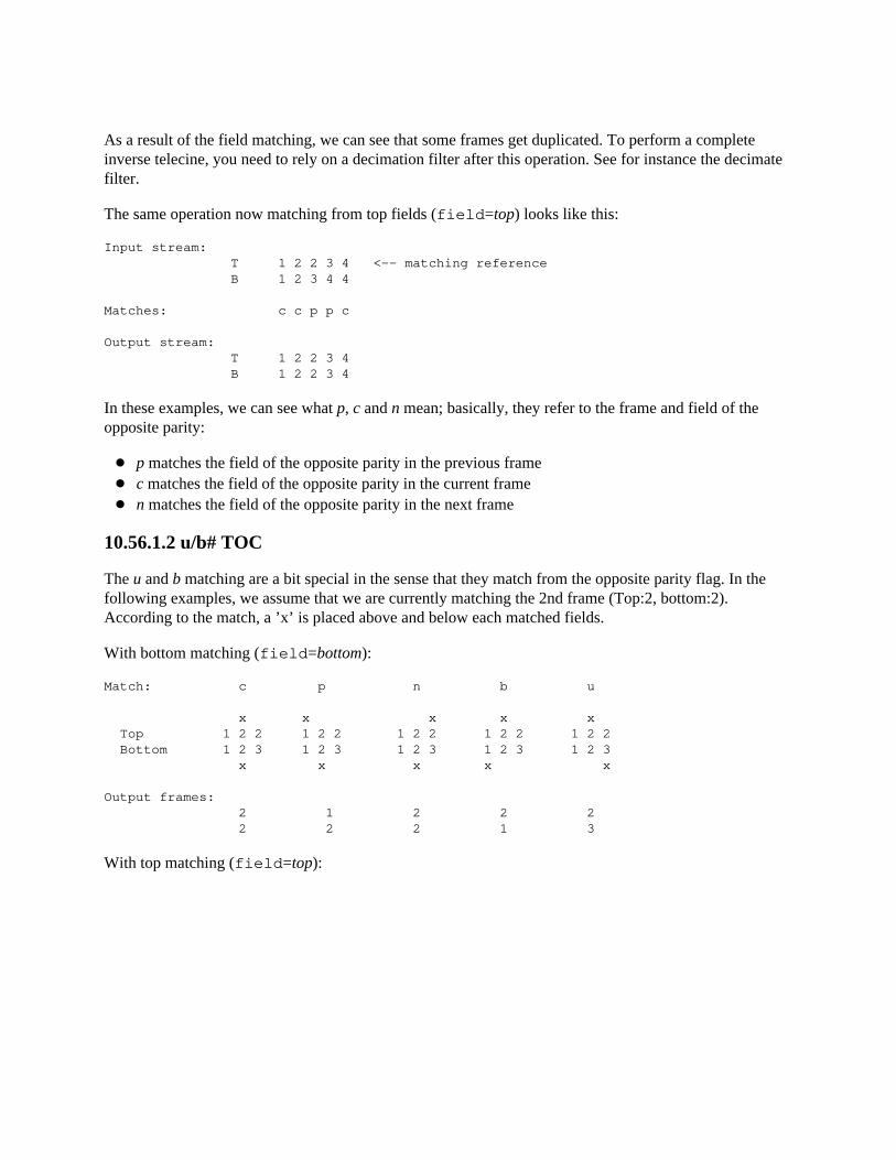
As a result of the field matching, we can see that some frames get duplicated. To perform a completeinverse telecine, you need to rely on a decimation filter after this operation. See for instance the decimate filter.
The same operation now matching from top fields (field=top) looks like this:
Input stream: T 1 2 2 3 4 <-- matching reference B 1 2 3 4 4
Matches: c c p p c
Output stream: T 1 2 2 3 4 B 1 2 2 3 4
In these examples, we can see what p, c and n mean; basically, they refer to the frame and field of theopposite parity:
p matches the field of the opposite parity in the previous framec matches the field of the opposite parity in the current framen matches the field of the opposite parity in the next frame
10.56.1.2 u/b# TOC
The u and b matching are a bit special in the sense that they match from the opposite parity flag. In thefollowing examples, we assume that we are currently matching the 2nd frame (Top:2, bottom:2).According to the match, a ’x’ is placed above and below each matched fields.
With bottom matching (field=bottom):
Match: c p n b u
x x x x x Top 1 2 2 1 2 2 1 2 2 1 2 2 1 2 2 Bottom 1 2 3 1 2 3 1 2 3 1 2 3 1 2 3 x x x x x
Output frames: 2 1 2 2 2 2 2 2 1 3
With top matching (field=top):
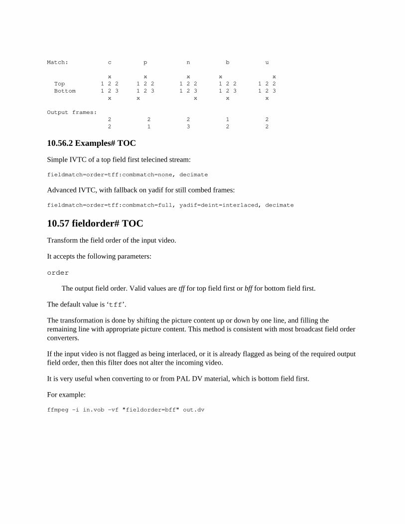
Match: c p n b u
x x x x x Top 1 2 2 1 2 2 1 2 2 1 2 2 1 2 2 Bottom 1 2 3 1 2 3 1 2 3 1 2 3 1 2 3 x x x x x
Output frames: 2 2 2 1 2 2 1 3 2 2
10.56.2 Examples# TOC
Simple IVTC of a top field first telecined stream:
fieldmatch=order=tff:combmatch=none, decimate
Advanced IVTC, with fallback on yadif for still combed frames:
fieldmatch=order=tff:combmatch=full, yadif=deint=interlaced, decimate
10.57 fieldorder# TOC
Transform the field order of the input video.
It accepts the following parameters:
order
The output field order. Valid values are tff for top field first or bff for bottom field first.
The default value is ‘tff’.
The transformation is done by shifting the picture content up or down by one line, and filling theremaining line with appropriate picture content. This method is consistent with most broadcast field order converters.
If the input video is not flagged as being interlaced, or it is already flagged as being of the required outputfield order, then this filter does not alter the incoming video.
It is very useful when converting to or from PAL DV material, which is bottom field first.
For example:
ffmpeg -i in.vob -vf "fieldorder=bff" out.dv
10.58 fifo, afifo# TOC
Buffer input images and send them when they are requested.
It is mainly useful when auto-inserted by the libavfilter framework.
It does not take parameters.
10.59 fillborders# TOC
Fill borders of the input video, without changing video stream dimensions. Sometimes video can havegarbage at the four edges and you may not want to crop video input to keep size multiple of some number.
This filter accepts the following options:
left
Number of pixels to fill from left border.
right
Number of pixels to fill from right border.
top
Number of pixels to fill from top border.
bottom
Number of pixels to fill from bottom border.
mode
Set fill mode.
It accepts the following values:
‘smear’
fill pixels using outermost pixels
‘mirror’
fill pixels using mirroring
‘fixed’
fill pixels with constant value
Default is smear.
color
Set color for pixels in fixed mode. Default is black.
10.60 find_rect# TOC
Find a rectangular object
It accepts the following options:
object
Filepath of the object image, needs to be in gray8.
threshold
Detection threshold, default is 0.5.
mipmaps
Number of mipmaps, default is 3.
xmin, ymin, xmax, ymax
Specifies the rectangle in which to search.
10.60.1 Examples# TOC
Generate a representative palette of a given video using ffmpeg:
ffmpeg -i file.ts -vf find_rect=newref.pgm,cover_rect=cover.jpg:mode=cover new.mkv
10.61 cover_rect# TOC
Cover a rectangular object
It accepts the following options:
cover
Filepath of the optional cover image, needs to be in yuv420.
mode
Set covering mode.
It accepts the following values:
‘cover’
cover it by the supplied image
‘blur’
cover it by interpolating the surrounding pixels
Default value is blur.
10.61.1 Examples# TOC
Generate a representative palette of a given video using ffmpeg:
ffmpeg -i file.ts -vf find_rect=newref.pgm,cover_rect=cover.jpg:mode=cover new.mkv
10.62 floodfill# TOC
Flood area with values of same pixel components with another values.
It accepts the following options:
x
Set pixel x coordinate.
y
Set pixel y coordinate.
s0
Set source #0 component value.
s1
Set source #1 component value.
s2
Set source #2 component value.
s3

Set source #3 component value.
d0
Set destination #0 component value.
d1
Set destination #1 component value.
d2
Set destination #2 component value.
d3
Set destination #3 component value.
10.63 format# TOC
Convert the input video to one of the specified pixel formats. Libavfilter will try to pick one that issuitable as input to the next filter.
It accepts the following parameters:
pix_fmts
A ’|’-separated list of pixel format names, such as "pix_fmts=yuv420p|monow|rgb24".
10.63.1 Examples# TOC
Convert the input video to the yuv420p format
format=pix_fmts=yuv420p
Convert the input video to any of the formats in the list
format=pix_fmts=yuv420p|yuv444p|yuv410p
10.64 fps# TOC
Convert the video to specified constant frame rate by duplicating or dropping frames as necessary.
It accepts the following parameters:
fps
The desired output frame rate. The default is 25.
start_time
Assume the first PTS should be the given value, in seconds. This allows for padding/trimming at thestart of stream. By default, no assumption is made about the first frame’s expected PTS, so nopadding or trimming is done. For example, this could be set to 0 to pad the beginning with duplicatesof the first frame if a video stream starts after the audio stream or to trim any frames with a negative PTS.
round
Timestamp (PTS) rounding method.
Possible values are:
zero
round towards 0
inf
round away from 0
down
round towards -infinity
up
round towards +infinity
near
round to nearest
The default is near.
eof_action
Action performed when reading the last frame.
Possible values are:
round
Use same timestamp rounding method as used for other frames.
pass
Pass through last frame if input duration has not been reached yet.
The default is round.
Alternatively, the options can be specified as a flat string: fps[:start_time[:round]].
See also the setpts filter.
10.64.1 Examples# TOC
A typical usage in order to set the fps to 25:
fps=fps=25
Sets the fps to 24, using abbreviation and rounding method to round to nearest:
fps=fps=film:round=near
10.65 framepack# TOC
Pack two different video streams into a stereoscopic video, setting proper metadata on supported codecs.The two views should have the same size and framerate and processing will stop when the shorter videoends. Please note that you may conveniently adjust view properties with the scale and fps filters.
It accepts the following parameters:
format
The desired packing format. Supported values are:
sbs
The views are next to each other (default).
tab
The views are on top of each other.
lines
The views are packed by line.
columns
The views are packed by column.

frameseq
The views are temporally interleaved.
Some examples:
# Convert left and right views into a frame-sequential videoffmpeg -i LEFT -i RIGHT -filter_complex framepack=frameseq OUTPUT
# Convert views into a side-by-side video with the same output resolution as the inputffmpeg -i LEFT -i RIGHT -filter_complex [0:v]scale=w=iw/2[left],[1:v]scale=w=iw/2[right],[left][right]framepack=sbs OUTPUT
10.66 framerate# TOC
Change the frame rate by interpolating new video output frames from the source frames.
This filter is not designed to function correctly with interlaced media. If you wish to change the frame rateof interlaced media then you are required to deinterlace before this filter and re-interlace after this filter.
A description of the accepted options follows.
fps
Specify the output frames per second. This option can also be specified as a value alone. The defaultis 50.
interp_start
Specify the start of a range where the output frame will be created as a linear interpolation of twoframes. The range is [0-255], the default is 15.
interp_end
Specify the end of a range where the output frame will be created as a linear interpolation of twoframes. The range is [0-255], the default is 240.
scene
Specify the level at which a scene change is detected as a value between 0 and 100 to indicate a newscene; a low value reflects a low probability for the current frame to introduce a new scene, while ahigher value means the current frame is more likely to be one. The default is 8.2.
flags
Specify flags influencing the filter process.
Available value for flags is:
scene_change_detect, scd
Enable scene change detection using the value of the option scene. This flag is enabled by default.
10.67 framestep# TOC
Select one frame every N-th frame.
This filter accepts the following option:
step
Select frame after every step frames. Allowed values are positive integers higher than 0. Defaultvalue is 1.
10.68 frei0r# TOC
Apply a frei0r effect to the input video.
To enable the compilation of this filter, you need to install the frei0r header and configure FFmpeg with --enable-frei0r.
It accepts the following parameters:
filter_name
The name of the frei0r effect to load. If the environment variable FREI0R_PATH is defined, thefrei0r effect is searched for in each of the directories specified by the colon-separated list in FREI0R_PATH. Otherwise, the standard frei0r paths are searched, in this order: HOME/.frei0r-1/lib/, /usr/local/lib/frei0r-1/, /usr/lib/frei0r-1/.
filter_params
A ’|’-separated list of parameters to pass to the frei0r effect.
A frei0r effect parameter can be a boolean (its value is either "y" or "n"), a double, a color (specified as R/G/B, where R, G, and B are floating point numbers between 0.0 and 1.0, inclusive) or a color descriptionas specified in the (ffmpeg-utils)"Color" section in the ffmpeg-utils manual, a position (specified as X/Y,where X and Y are floating point numbers) and/or a string.
The number and types of parameters depend on the loaded effect. If an effect parameter is not specified,the default value is set.
10.68.1 Examples# TOC
Apply the distort0r effect, setting the first two double parameters:
frei0r=filter_name=distort0r:filter_params=0.5|0.01
Apply the colordistance effect, taking a color as the first parameter:
frei0r=colordistance:0.2/0.3/0.4frei0r=colordistance:violetfrei0r=colordistance:0x112233
Apply the perspective effect, specifying the top left and top right image positions:
frei0r=perspective:0.2/0.2|0.8/0.2
For more information, see http://frei0r.dyne.org
10.69 fspp# TOC
Apply fast and simple postprocessing. It is a faster version of spp.
It splits (I)DCT into horizontal/vertical passes. Unlike the simple post- processing filter, one of them isperformed once per block, not per pixel. This allows for much higher speed.
The filter accepts the following options:
quality
Set quality. This option defines the number of levels for averaging. It accepts an integer in the range4-5. Default value is 4.
qp
Force a constant quantization parameter. It accepts an integer in range 0-63. If not set, the filter willuse the QP from the video stream (if available).
strength
Set filter strength. It accepts an integer in range -15 to 32. Lower values mean more details but alsomore artifacts, while higher values make the image smoother but also blurrier. Default value is 0 âPSNR optimal.
use_bframe_qp
Enable the use of the QP from the B-Frames if set to 1. Using this option may cause flicker since theB-Frames have often larger QP. Default is 0 (not enabled).
10.70 gblur# TOC
Apply Gaussian blur filter.
The filter accepts the following options:
sigma
Set horizontal sigma, standard deviation of Gaussian blur. Default is 0.5.
steps
Set number of steps for Gaussian approximation. Defauls is 1.
planes
Set which planes to filter. By default all planes are filtered.
sigmaV
Set vertical sigma, if negative it will be same as sigma. Default is -1.
10.71 geq# TOC
The filter accepts the following options:
lum_expr, lum
Set the luminance expression.
cb_expr, cb
Set the chrominance blue expression.
cr_expr, cr
Set the chrominance red expression.
alpha_expr, a
Set the alpha expression.
red_expr, r
Set the red expression.
green_expr, g
Set the green expression.
blue_expr, b
Set the blue expression.
The colorspace is selected according to the specified options. If one of the lum_expr, cb_expr, or cr_expr options is specified, the filter will automatically select a YCbCr colorspace. If one of the red_expr, green_expr, or blue_expr options is specified, it will select an RGB colorspace.
If one of the chrominance expression is not defined, it falls back on the other one. If no alpha expression isspecified it will evaluate to opaque value. If none of chrominance expressions are specified, they willevaluate to the luminance expression.
The expressions can use the following variables and functions:
N
The sequential number of the filtered frame, starting from 0.
X Y
The coordinates of the current sample.
W H
The width and height of the image.
SW SH
Width and height scale depending on the currently filtered plane. It is the ratio between thecorresponding luma plane number of pixels and the current plane ones. E.g. for YUV4:2:0 the valuesare 1,1 for the luma plane, and 0.5,0.5 for chroma planes.
T
Time of the current frame, expressed in seconds.
p(x, y)
Return the value of the pixel at location (x,y) of the current plane.
lum(x, y)
Return the value of the pixel at location (x,y) of the luminance plane.
cb(x, y)
Return the value of the pixel at location (x,y) of the blue-difference chroma plane. Return 0 if there isno such plane.
cr(x, y)
Return the value of the pixel at location (x,y) of the red-difference chroma plane. Return 0 if there isno such plane.
r(x, y) g(x, y) b(x, y)
Return the value of the pixel at location (x,y) of the red/green/blue component. Return 0 if there is nosuch component.
alpha(x, y)
Return the value of the pixel at location (x,y) of the alpha plane. Return 0 if there is no such plane.
For functions, if x and y are outside the area, the value will be automatically clipped to the closer edge.
10.71.1 Examples# TOC
Flip the image horizontally:
geq=p(W-X\,Y)
Generate a bidimensional sine wave, with angle PI/3 and a wavelength of 100 pixels:
geq=128 + 100*sin(2*(PI/100)*(cos(PI/3)*(X-50*T) + sin(PI/3)*Y)):128:128
Generate a fancy enigmatic moving light:
nullsrc=s=256x256,geq=random(1)/hypot(X-cos(N*0.07)*W/2-W/2\,Y-sin(N*0.09)*H/2-H/2)^2*1000000*sin(N*0.02):128:128
Generate a quick emboss effect:
format=gray,geq=lum_expr=’(p(X,Y)+(256-p(X-4,Y-4)))/2’
Modify RGB components depending on pixel position:
geq=r=’X/W*r(X,Y)’:g=’(1-X/W)*g(X,Y)’:b=’(H-Y)/H*b(X,Y)’
Create a radial gradient that is the same size as the input (also see the vignette filter):
geq=lum=255*gauss((X/W-0.5)*3)*gauss((Y/H-0.5)*3)/gauss(0)/gauss(0),format=gray

10.72 gradfun# TOC
Fix the banding artifacts that are sometimes introduced into nearly flat regions by truncation to 8-bit colordepth. Interpolate the gradients that should go where the bands are, and dither them.
It is designed for playback only. Do not use it prior to lossy compression, because compression tends tolose the dither and bring back the bands.
It accepts the following parameters:
strength
The maximum amount by which the filter will change any one pixel. This is also the threshold fordetecting nearly flat regions. Acceptable values range from .51 to 64; the default value is 1.2.Out-of-range values will be clipped to the valid range.
radius
The neighborhood to fit the gradient to. A larger radius makes for smoother gradients, but alsoprevents the filter from modifying the pixels near detailed regions. Acceptable values are 8-32; thedefault value is 16. Out-of-range values will be clipped to the valid range.
Alternatively, the options can be specified as a flat string: strength[:radius]
10.72.1 Examples# TOC
Apply the filter with a 3.5 strength and radius of 8:
gradfun=3.5:8
Specify radius, omitting the strength (which will fall-back to the default value):
gradfun=radius=8
10.73 haldclut# TOC
Apply a Hald CLUT to a video stream.
First input is the video stream to process, and second one is the Hald CLUT. The Hald CLUT input can bea simple picture or a complete video stream.
The filter accepts the following options:
shortest
Force termination when the shortest input terminates. Default is 0.
repeatlast
Continue applying the last CLUT after the end of the stream. A value of 0 disable the filter after thelast frame of the CLUT is reached. Default is 1.
haldclut also has the same interpolation options as lut3d (both filters share the same internals).
More information about the Hald CLUT can be found on Eskil Steenberg’s website (Hald CLUT author)at http://www.quelsolaar.com/technology/clut.html.
10.73.1 Workflow examples# TOC
10.73.1.1 Hald CLUT video stream# TOC
Generate an identity Hald CLUT stream altered with various effects:
ffmpeg -f lavfi -i haldclutsrc=8 -vf "hue=H=2*PI*t:s=sin(2*PI*t)+1, curves=cross_process" -t 10 -c:v ffv1 clut.nut
Note: make sure you use a lossless codec.
Then use it with haldclut to apply it on some random stream:
ffmpeg -f lavfi -i mandelbrot -i clut.nut -filter_complex ’[0][1] haldclut’ -t 20 mandelclut.mkv
The Hald CLUT will be applied to the 10 first seconds (duration of clut.nut), then the latest picture ofthat CLUT stream will be applied to the remaining frames of the mandelbrot stream.
10.73.1.2 Hald CLUT with preview# TOC
A Hald CLUT is supposed to be a squared image of Level*Level*Level by Level*Level*Level pixels. For a given Hald CLUT, FFmpeg will select the biggest possible squarestarting at the top left of the picture. The remaining padding pixels (bottom or right) will be ignored. Thisarea can be used to add a preview of the Hald CLUT.
Typically, the following generated Hald CLUT will be supported by the haldclut filter:
ffmpeg -f lavfi -i haldclutsrc=8 -vf " pad=iw+320 [padded_clut]; smptebars=s=320x256, split [a][b]; [padded_clut][a] overlay=W-320:h, curves=color_negative [main]; [main][b] overlay=W-320" -frames:v 1 clut.png
It contains the original and a preview of the effect of the CLUT: SMPTE color bars are displayed on theright-top, and below the same color bars processed by the color changes.
Then, the effect of this Hald CLUT can be visualized with:
ffplay input.mkv -vf "movie=clut.png, [in] haldclut"
10.74 hflip# TOC
Flip the input video horizontally.
For example, to horizontally flip the input video with ffmpeg:
ffmpeg -i in.avi -vf "hflip" out.avi
10.75 histeq# TOC
This filter applies a global color histogram equalization on a per-frame basis.
It can be used to correct video that has a compressed range of pixel intensities. The filter redistributes thepixel intensities to equalize their distribution across the intensity range. It may be viewed as an"automatically adjusting contrast filter". This filter is useful only for correcting degraded or poorlycaptured source video.
The filter accepts the following options:
strength
Determine the amount of equalization to be applied. As the strength is reduced, the distribution ofpixel intensities more-and-more approaches that of the input frame. The value must be a float numberin the range [0,1] and defaults to 0.200.
intensity
Set the maximum intensity that can generated and scale the output values appropriately. The strengthshould be set as desired and then the intensity can be limited if needed to avoid washing-out. Thevalue must be a float number in the range [0,1] and defaults to 0.210.
antibanding
Set the antibanding level. If enabled the filter will randomly vary the luminance of output pixels by asmall amount to avoid banding of the histogram. Possible values are none, weak or strong. Itdefaults to none.
10.76 histogram# TOC
Compute and draw a color distribution histogram for the input video.
The computed histogram is a representation of the color component distribution in an image.
Standard histogram displays the color components distribution in an image. Displays color graph for eachcolor component. Shows distribution of the Y, U, V, A or R, G, B components, depending on inputformat, in the current frame. Below each graph a color component scale meter is shown.
The filter accepts the following options:
level_height
Set height of level. Default value is 200. Allowed range is [50, 2048].
scale_height
Set height of color scale. Default value is 12. Allowed range is [0, 40].
display_mode
Set display mode. It accepts the following values:
‘stack’
Per color component graphs are placed below each other.
‘parade’
Per color component graphs are placed side by side.
‘overlay’
Presents information identical to that in the parade, except that the graphs representing colorcomponents are superimposed directly over one another.
Default is stack.
levels_mode
Set mode. Can be either linear, or logarithmic. Default is linear.
components
Set what color components to display. Default is 7.
fgopacity
Set foreground opacity. Default is 0.7.
bgopacity
Set background opacity. Default is 0.5.
10.76.1 Examples# TOC
Calculate and draw histogram:
ffplay -i input -vf histogram
10.77 hqdn3d# TOC
This is a high precision/quality 3d denoise filter. It aims to reduce image noise, producing smooth imagesand making still images really still. It should enhance compressibility.
It accepts the following optional parameters:
luma_spatial
A non-negative floating point number which specifies spatial luma strength. It defaults to 4.0.
chroma_spatial
A non-negative floating point number which specifies spatial chroma strength. It defaults to 3.0*luma_spatial/4.0.
luma_tmp
A floating point number which specifies luma temporal strength. It defaults to 6.0*luma_spatial/4.0.
chroma_tmp
A floating point number which specifies chroma temporal strength. It defaults to luma_tmp*chroma_spatial/luma_spatial.
10.78 hwdownload# TOC
Download hardware frames to system memory.
The input must be in hardware frames, and the output a non-hardware format. Not all formats will besupported on the output - it may be necessary to insert an additional format filter immediately followingin the graph to get the output in a supported format.
10.79 hwmap# TOC
Map hardware frames to system memory or to another device.
This filter has several different modes of operation; which one is used depends on the input and output formats:
Hardware frame input, normal frame output
Map the input frames to system memory and pass them to the output. If the original hardware frameis later required (for example, after overlaying something else on part of it), the hwmap filter can beused again in the next mode to retrieve it.
Normal frame input, hardware frame output
If the input is actually a software-mapped hardware frame, then unmap it - that is, return the originalhardware frame.
Otherwise, a device must be provided. Create new hardware surfaces on that device for the output,then map them back to the software format at the input and give those frames to the preceding filter.This will then act like the hwupload filter, but may be able to avoid an additional copy when theinput is already in a compatible format.
Hardware frame input and output
A device must be supplied for the output, either directly or with the derive_device option. Theinput and output devices must be of different types and compatible - the exact meaning of this issystem-dependent, but typically it means that they must refer to the same underlying hardwarecontext (for example, refer to the same graphics card).
If the input frames were originally created on the output device, then unmap to retrieve the original frames.
Otherwise, map the frames to the output device - create new hardware frames on the outputcorresponding to the frames on the input.
The following additional parameters are accepted:
mode
Set the frame mapping mode. Some combination of:
read
The mapped frame should be readable.
write
The mapped frame should be writeable.
overwrite
The mapping will always overwrite the entire frame.
This may improve performance in some cases, as the original contents of the frame need not be loaded.
direct
The mapping must not involve any copying.
Indirect mappings to copies of frames are created in some cases where either direct mapping isnot possible or it would have unexpected properties. Setting this flag ensures that the mapping isdirect and will fail if that is not possible.
Defaults to read+write if not specified.
derive_device type
Rather than using the device supplied at initialisation, instead derive a new device of type type fromthe device the input frames exist on.
reverse
In a hardware to hardware mapping, map in reverse - create frames in the sink and map them back tothe source. This may be necessary in some cases where a mapping in one direction is required butonly the opposite direction is supported by the devices being used.
This option is dangerous - it may break the preceding filter in undefined ways if there are anyadditional constraints on that filter’s output. Do not use it without fully understanding theimplications of its use.
10.80 hwupload# TOC
Upload system memory frames to hardware surfaces.
The device to upload to must be supplied when the filter is initialised. If using ffmpeg, select theappropriate device with the -filter_hw_device option.
10.81 hwupload_cuda# TOC
Upload system memory frames to a CUDA device.
It accepts the following optional parameters:
device
The number of the CUDA device to use
10.82 hqx# TOC
Apply a high-quality magnification filter designed for pixel art. This filter was originally created byMaxim Stepin.
It accepts the following option:
n
Set the scaling dimension: 2 for hq2x, 3 for hq3x and 4 for hq4x. Default is 3.
10.83 hstack# TOC
Stack input videos horizontally.
All streams must be of same pixel format and of same height.
Note that this filter is faster than using overlay and pad filter to create same output.
The filter accept the following option:
inputs
Set number of input streams. Default is 2.
shortest
If set to 1, force the output to terminate when the shortest input terminates. Default value is 0.
10.84 hue# TOC
Modify the hue and/or the saturation of the input.
It accepts the following parameters:
h
Specify the hue angle as a number of degrees. It accepts an expression, and defaults to "0".
s
Specify the saturation in the [-10,10] range. It accepts an expression and defaults to "1".
H
Specify the hue angle as a number of radians. It accepts an expression, and defaults to "0".
b
Specify the brightness in the [-10,10] range. It accepts an expression and defaults to "0".
h and H are mutually exclusive, and can’t be specified at the same time.
The b, h, H and s option values are expressions containing the following constants:
n
frame count of the input frame starting from 0
pts
presentation timestamp of the input frame expressed in time base units
r
frame rate of the input video, NAN if the input frame rate is unknown
t
timestamp expressed in seconds, NAN if the input timestamp is unknown
tb
time base of the input video
10.84.1 Examples# TOC
Set the hue to 90 degrees and the saturation to 1.0:
hue=h=90:s=1
Same command but expressing the hue in radians:
hue=H=PI/2:s=1
Rotate hue and make the saturation swing between 0 and 2 over a period of 1 second:
hue="H=2*PI*t: s=sin(2*PI*t)+1"
Apply a 3 seconds saturation fade-in effect starting at 0:
hue="s=min(t/3\,1)"
The general fade-in expression can be written as:
hue="s=min(0\, max((t-START)/DURATION\, 1))"
Apply a 3 seconds saturation fade-out effect starting at 5 seconds:
hue="s=max(0\, min(1\, (8-t)/3))"
The general fade-out expression can be written as:
hue="s=max(0\, min(1\, (START+DURATION-t)/DURATION))"
10.84.2 Commands# TOC
This filter supports the following commands:
b s h H
Modify the hue and/or the saturation and/or brightness of the input video. The command accepts thesame syntax of the corresponding option.
If the specified expression is not valid, it is kept at its current value.
10.85 hysteresis# TOC
Grow first stream into second stream by connecting components. This makes it possible to build morerobust edge masks.
This filter accepts the following options:
planes
Set which planes will be processed as bitmap, unprocessed planes will be copied from first stream.By default value 0xf, all planes will be processed.
threshold
Set threshold which is used in filtering. If pixel component value is higher than this value filteralgorithm for connecting components is activated. By default value is 0.
10.86 idet# TOC
Detect video interlacing type.
This filter tries to detect if the input frames are interlaced, progressive, top or bottom field first. It will alsotry to detect fields that are repeated between adjacent frames (a sign of telecine).
Single frame detection considers only immediately adjacent frames when classifying each frame. Multipleframe detection incorporates the classification history of previous frames.
The filter will log these metadata values:
single.current_frame
Detected type of current frame using single-frame detection. One of: “tff” (top field first), “bff”(bottom field first), “progressive”, or “undetermined”
single.tff
Cumulative number of frames detected as top field first using single-frame detection.
multiple.tff
Cumulative number of frames detected as top field first using multiple-frame detection.
single.bff
Cumulative number of frames detected as bottom field first using single-frame detection.
multiple.current_frame
Detected type of current frame using multiple-frame detection. One of: “tff” (top field first), “bff”(bottom field first), “progressive”, or “undetermined”
multiple.bff
Cumulative number of frames detected as bottom field first using multiple-frame detection.
single.progressive
Cumulative number of frames detected as progressive using single-frame detection.
multiple.progressive
Cumulative number of frames detected as progressive using multiple-frame detection.
single.undetermined
Cumulative number of frames that could not be classified using single-frame detection.
multiple.undetermined
Cumulative number of frames that could not be classified using multiple-frame detection.
repeated.current_frame
Which field in the current frame is repeated from the last. One of “neither”, “top”, or “bottom”.
repeated.neither
Cumulative number of frames with no repeated field.
repeated.top
Cumulative number of frames with the top field repeated from the previous frame’s top field.
repeated.bottom
Cumulative number of frames with the bottom field repeated from the previous frame’s bottom field.
The filter accepts the following options:
intl_thres
Set interlacing threshold.
prog_thres
Set progressive threshold.
rep_thres
Threshold for repeated field detection.
half_life
Number of frames after which a given frame’s contribution to the statistics is halved (i.e., itcontributes only 0.5 to its classification). The default of 0 means that all frames seen are given fullweight of 1.0 forever.
analyze_interlaced_flag
When this is not 0 then idet will use the specified number of frames to determine if the interlaced flagis accurate, it will not count undetermined frames. If the flag is found to be accurate it will be usedwithout any further computations, if it is found to be inaccurate it will be cleared without any furthercomputations. This allows inserting the idet filter as a low computational method to clean up theinterlaced flag
10.87 il# TOC
Deinterleave or interleave fields.
This filter allows one to process interlaced images fields without deinterlacing them. Deinterleaving splitsthe input frame into 2 fields (so called half pictures). Odd lines are moved to the top half of the outputimage, even lines to the bottom half. You can process (filter) them independently and then re-interleave them.
The filter accepts the following options:
luma_mode, l chroma_mode, c alpha_mode, a
Available values for luma_mode, chroma_mode and alpha_mode are:
‘none’
Do nothing.
‘deinterleave, d’
Deinterleave fields, placing one above the other.
‘interleave, i’
Interleave fields. Reverse the effect of deinterleaving.
Default value is none.
luma_swap, ls chroma_swap, cs alpha_swap, as
Swap luma/chroma/alpha fields. Exchange even & odd lines. Default value is 0.
10.88 inflate# TOC
Apply inflate effect to the video.
This filter replaces the pixel by the local(3x3) average by taking into account only values higher than the pixel.
It accepts the following options:
threshold0 threshold1 threshold2 threshold3
Limit the maximum change for each plane, default is 65535. If 0, plane will remain unchanged.
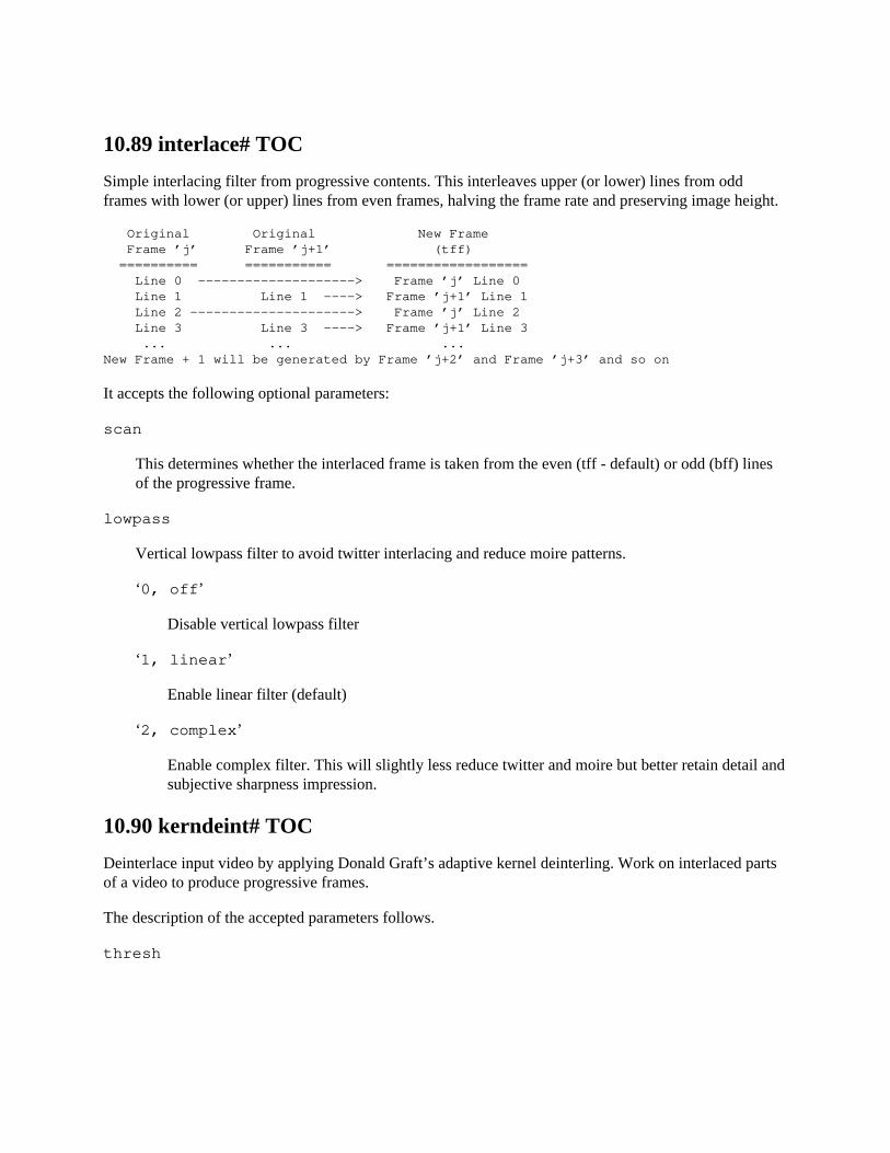
10.89 interlace# TOC
Simple interlacing filter from progressive contents. This interleaves upper (or lower) lines from oddframes with lower (or upper) lines from even frames, halving the frame rate and preserving image height.
Original Original New Frame Frame ’j’ Frame ’j+1’ (tff) ========== =========== ================== Line 0 --------------------> Frame ’j’ Line 0 Line 1 Line 1 ----> Frame ’j+1’ Line 1 Line 2 ---------------------> Frame ’j’ Line 2 Line 3 Line 3 ----> Frame ’j+1’ Line 3 ... ... ...New Frame + 1 will be generated by Frame ’j+2’ and Frame ’j+3’ and so on
It accepts the following optional parameters:
scan
This determines whether the interlaced frame is taken from the even (tff - default) or odd (bff) linesof the progressive frame.
lowpass
Vertical lowpass filter to avoid twitter interlacing and reduce moire patterns.
‘0, off’
Disable vertical lowpass filter
‘1, linear’
Enable linear filter (default)
‘2, complex’
Enable complex filter. This will slightly less reduce twitter and moire but better retain detail andsubjective sharpness impression.
10.90 kerndeint# TOC
Deinterlace input video by applying Donald Graft’s adaptive kernel deinterling. Work on interlaced partsof a video to produce progressive frames.
The description of the accepted parameters follows.
thresh
Set the threshold which affects the filter’s tolerance when determining if a pixel line must beprocessed. It must be an integer in the range [0,255] and defaults to 10. A value of 0 will result in applyingthe process on every pixels.
map
Paint pixels exceeding the threshold value to white if set to 1. Default is 0.
order
Set the fields order. Swap fields if set to 1, leave fields alone if 0. Default is 0.
sharp
Enable additional sharpening if set to 1. Default is 0.
twoway
Enable twoway sharpening if set to 1. Default is 0.
10.90.1 Examples# TOC
Apply default values:
kerndeint=thresh=10:map=0:order=0:sharp=0:twoway=0
Enable additional sharpening:
kerndeint=sharp=1
Paint processed pixels in white:
kerndeint=map=1
10.91 lenscorrection# TOC
Correct radial lens distortion
This filter can be used to correct for radial distortion as can result from the use of wide angle lenses, andthereby re-rectify the image. To find the right parameters one can use tools available for example as partof opencv or simply trial-and-error. To use opencv use the calibration sample (under samples/cpp) fromthe opencv sources and extract the k1 and k2 coefficients from the resulting matrix.
Note that effectively the same filter is available in the open-source tools Krita and Digikam from the KDE project.
In contrast to the vignette filter, which can also be used to compensate lens errors, this filter corrects thedistortion of the image, whereas vignette corrects the brightness distribution, so you may want to use bothfilters together in certain cases, though you will have to take care of ordering, i.e. whether vignettingshould be applied before or after lens correction.

10.91.1 Options# TOC
The filter accepts the following options:
cx
Relative x-coordinate of the focal point of the image, and thereby the center of the distortion. Thisvalue has a range [0,1] and is expressed as fractions of the image width. Default is 0.5.
cy
Relative y-coordinate of the focal point of the image, and thereby the center of the distortion. Thisvalue has a range [0,1] and is expressed as fractions of the image height. Default is 0.5.
k1
Coefficient of the quadratic correction term. This value has a range [-1,1]. 0 means no correction.Default is 0.
k2
Coefficient of the double quadratic correction term. This value has a range [-1,1]. 0 means nocorrection. Default is 0.
The formula that generates the correction is:
r_src = r_tgt * (1 + k1 * (r_tgt / r_0)^2 + k2 * (r_tgt / r_0)^4)
where r_0 is halve of the image diagonal and r_src and r_tgt are the distances from the focal point in thesource and target images, respectively.
10.92 libvmaf# TOC
Obtain the VMAF (Video Multi-Method Assessment Fusion) score between two input videos.
The obtained VMAF score is printed through the logging system.
It requires Netflix’s vmaf library (libvmaf) as a pre-requisite. After installing the library it can be enabledusing: ./configure --enable-libvmaf. If no model path is specified it uses the default model: vmaf_v0.6.1.pkl.
The filter has following options:
model_path
Set the model path which is to be used for SVM. Default value: "vmaf_v0.6.1.pkl"
log_path
Set the file path to be used to store logs.
log_fmt
Set the format of the log file (xml or json).
enable_transform
Enables transform for computing vmaf.
phone_model
Invokes the phone model which will generate VMAF scores higher than in the regular model, whichis more suitable for laptop, TV, etc. viewing conditions.
psnr
Enables computing psnr along with vmaf.
ssim
Enables computing ssim along with vmaf.
ms_ssim
Enables computing ms_ssim along with vmaf.
pool
Set the pool method (mean, min or harmonic mean) to be used for computing vmaf.
This filter also supports the framesync options.
On the below examples the input file main.mpg being processed is compared with the reference file ref.mpg.
ffmpeg -i main.mpg -i ref.mpg -lavfi libvmaf -f null -
Example with options:
ffmpeg -i main.mpg -i ref.mpg -lavfi libvmaf="psnr=1:enable-transform=1" -f null -
10.93 limiter# TOC
Limits the pixel components values to the specified range [min, max].
The filter accepts the following options:
min
Lower bound. Defaults to the lowest allowed value for the input.
max
Upper bound. Defaults to the highest allowed value for the input.
planes
Specify which planes will be processed. Defaults to all available.
10.94 loop# TOC
Loop video frames.
The filter accepts the following options:
loop
Set the number of loops. Setting this value to -1 will result in infinite loops. Default is 0.
size
Set maximal size in number of frames. Default is 0.
start
Set first frame of loop. Default is 0.
10.95 lut3d# TOC
Apply a 3D LUT to an input video.
The filter accepts the following options:
file
Set the 3D LUT file name.
Currently supported formats:
‘3dl’
AfterEffects
‘cube’
Iridas
‘dat’
DaVinci
‘m3d’
Pandora
interp
Select interpolation mode.
Available values are:
‘nearest’
Use values from the nearest defined point.
‘trilinear’
Interpolate values using the 8 points defining a cube.
‘tetrahedral’
Interpolate values using a tetrahedron.
This filter also supports the framesync options.
10.96 lumakey# TOC
Turn certain luma values into transparency.
The filter accepts the following options:
threshold
Set the luma which will be used as base for transparency. Default value is 0.
tolerance
Set the range of luma values to be keyed out. Default value is 0.
softness

Set the range of softness. Default value is 0. Use this to control gradual transition from zero to full transparency.
10.97 lut, lutrgb, lutyuv# TOC
Compute a look-up table for binding each pixel component input value to an output value, and apply it tothe input video.
lutyuv applies a lookup table to a YUV input video, lutrgb to an RGB input video.
These filters accept the following parameters:
c0
set first pixel component expression
c1
set second pixel component expression
c2
set third pixel component expression
c3
set fourth pixel component expression, corresponds to the alpha component
r
set red component expression
g
set green component expression
b
set blue component expression
a
alpha component expression
y
set Y/luminance component expression
u
set U/Cb component expression
v
set V/Cr component expression
Each of them specifies the expression to use for computing the lookup table for the corresponding pixelcomponent values.
The exact component associated to each of the c* options depends on the format in input.
The lut filter requires either YUV or RGB pixel formats in input, lutrgb requires RGB pixel formats ininput, and lutyuv requires YUV.
The expressions can contain the following constants and functions:
w h
The input width and height.
val
The input value for the pixel component.
clipval
The input value, clipped to the minval-maxval range.
maxval
The maximum value for the pixel component.
minval
The minimum value for the pixel component.
negval
The negated value for the pixel component value, clipped to the minval-maxval range; it correspondsto the expression "maxval-clipval+minval".
clip(val)
The computed value in val, clipped to the minval-maxval range.
gammaval(gamma)
The computed gamma correction value of the pixel component value, clipped to the minval-maxvalrange. It corresponds to the expression "pow((clipval-minval)/(maxval-minval)\,gamma)*(maxval-minval)+minval"
All expressions default to "val".
10.97.1 Examples# TOC
Negate input video:
lutrgb="r=maxval+minval-val:g=maxval+minval-val:b=maxval+minval-val"lutyuv="y=maxval+minval-val:u=maxval+minval-val:v=maxval+minval-val"
The above is the same as:
lutrgb="r=negval:g=negval:b=negval"lutyuv="y=negval:u=negval:v=negval"
Negate luminance:
lutyuv=y=negval
Remove chroma components, turning the video into a graytone image:
lutyuv="u=128:v=128"
Apply a luma burning effect:
lutyuv="y=2*val"
Remove green and blue components:
lutrgb="g=0:b=0"
Set a constant alpha channel value on input:
format=rgba,lutrgb=a="maxval-minval/2"
Correct luminance gamma by a factor of 0.5:
lutyuv=y=gammaval(0.5)
Discard least significant bits of luma:
lutyuv=y=’bitand(val, 128+64+32)’
Technicolor like effect:
lutyuv=u=’(val-maxval/2)*2+maxval/2’:v=’(val-maxval/2)*2+maxval/2’
10.98 lut2, tlut2# TOC
The lut2 filter takes two input streams and outputs one stream.
The tlut2 (time lut2) filter takes two consecutive frames from one single stream.
This filter accepts the following parameters:
c0
set first pixel component expression
c1
set second pixel component expression
c2
set third pixel component expression
c3
set fourth pixel component expression, corresponds to the alpha component
Each of them specifies the expression to use for computing the lookup table for the corresponding pixelcomponent values.
The exact component associated to each of the c* options depends on the format in inputs.
The expressions can contain the following constants:
w h
The input width and height.
x
The first input value for the pixel component.
y
The second input value for the pixel component.
bdx
The first input video bit depth.
bdy
The second input video bit depth.
All expressions default to "x".
10.98.1 Examples# TOC
Highlight differences between two RGB video streams:
lut2=’ifnot(x-y,0,pow(2,bdx)-1):ifnot(x-y,0,pow(2,bdx)-1):ifnot(x-y,0,pow(2,bdx)-1)’
Highlight differences between two YUV video streams:
lut2=’ifnot(x-y,0,pow(2,bdx)-1):ifnot(x-y,pow(2,bdx-1),pow(2,bdx)-1):ifnot(x-y,pow(2,bdx-1),pow(2,bdx)-1)’
Show max difference between two video streams:
lut2=’if(lt(x,y),0,if(gt(x,y),pow(2,bdx)-1,pow(2,bdx-1))):if(lt(x,y),0,if(gt(x,y),pow(2,bdx)-1,pow(2,bdx-1))):if(lt(x,y),0,if(gt(x,y),pow(2,bdx)-1,pow(2,bdx-1)))’
10.99 maskedclamp# TOC
Clamp the first input stream with the second input and third input stream.
Returns the value of first stream to be between second input stream - undershoot and third input stream+ overshoot.
This filter accepts the following options:
undershoot
Default value is 0.
overshoot
Default value is 0.
planes
Set which planes will be processed as bitmap, unprocessed planes will be copied from first stream.By default value 0xf, all planes will be processed.
10.100 maskedmerge# TOC
Merge the first input stream with the second input stream using per pixel weights in the third input stream.
A value of 0 in the third stream pixel component means that pixel component from first stream is returnedunchanged, while maximum value (eg. 255 for 8-bit videos) means that pixel component from secondstream is returned unchanged. Intermediate values define the amount of merging between both inputstream’s pixel components.
This filter accepts the following options:
planes
Set which planes will be processed as bitmap, unprocessed planes will be copied from first stream.By default value 0xf, all planes will be processed.
10.101 mcdeint# TOC
Apply motion-compensation deinterlacing.
It needs one field per frame as input and must thus be used together with yadif=1/3 or equivalent.
This filter accepts the following options:
mode
Set the deinterlacing mode.
It accepts one of the following values:
‘fast’ ‘medium’ ‘slow’
use iterative motion estimation
‘extra_slow’
like ‘slow’, but use multiple reference frames.
Default value is ‘fast’.
parity
Set the picture field parity assumed for the input video. It must be one of the following values:
‘0, tff’
assume top field first
‘1, bff’
assume bottom field first
Default value is ‘bff’.
qp
Set per-block quantization parameter (QP) used by the internal encoder.
Higher values should result in a smoother motion vector field but less optimal individual vectors.Default value is 1.
10.102 mergeplanes# TOC
Merge color channel components from several video streams.
The filter accepts up to 4 input streams, and merge selected input planes to the output video.
This filter accepts the following options:
mapping
Set input to output plane mapping. Default is 0.
The mappings is specified as a bitmap. It should be specified as a hexadecimal number in the form0xAa[Bb[Cc[Dd]]]. ’Aa’ describes the mapping for the first plane of the output stream. ’A’ sets thenumber of the input stream to use (from 0 to 3), and ’a’ the plane number of the corresponding inputto use (from 0 to 3). The rest of the mappings is similar, ’Bb’ describes the mapping for the outputstream second plane, ’Cc’ describes the mapping for the output stream third plane and ’Dd’ describesthe mapping for the output stream fourth plane.
format
Set output pixel format. Default is yuva444p.
10.102.1 Examples# TOC
Merge three gray video streams of same width and height into single video stream:
[a0][a1][a2]mergeplanes=0x001020:yuv444p
Merge 1st yuv444p stream and 2nd gray video stream into yuva444p video stream:
[a0][a1]mergeplanes=0x00010210:yuva444p
Swap Y and A plane in yuva444p stream:
format=yuva444p,mergeplanes=0x03010200:yuva444p
Swap U and V plane in yuv420p stream:
format=yuv420p,mergeplanes=0x000201:yuv420p
Cast a rgb24 clip to yuv444p:

format=rgb24,mergeplanes=0x000102:yuv444p
10.103 mestimate# TOC
Estimate and export motion vectors using block matching algorithms. Motion vectors are stored in frameside data to be used by other filters.
This filter accepts the following options:
method
Specify the motion estimation method. Accepts one of the following values:
‘esa’
Exhaustive search algorithm.
‘tss’
Three step search algorithm.
‘tdls’
Two dimensional logarithmic search algorithm.
‘ntss’
New three step search algorithm.
‘fss’
Four step search algorithm.
‘ds’
Diamond search algorithm.
‘hexbs’
Hexagon-based search algorithm.
‘epzs’
Enhanced predictive zonal search algorithm.
‘umh’
Uneven multi-hexagon search algorithm.
Default value is ‘esa’.
mb_size
Macroblock size. Default 16.
search_param
Search parameter. Default 7.
10.104 midequalizer# TOC
Apply Midway Image Equalization effect using two video streams.
Midway Image Equalization adjusts a pair of images to have the same histogram, while maintaining theirdynamics as much as possible. It’s useful for e.g. matching exposures from a pair of stereo cameras.
This filter has two inputs and one output, which must be of same pixel format, but may be of differentsizes. The output of filter is first input adjusted with midway histogram of both inputs.
This filter accepts the following option:
planes
Set which planes to process. Default is 15, which is all available planes.
10.105 minterpolate# TOC
Convert the video to specified frame rate using motion interpolation.
This filter accepts the following options:
fps
Specify the output frame rate. This can be rational e.g. 60000/1001. Frames are dropped if fps islower than source fps. Default 60.
mi_mode
Motion interpolation mode. Following values are accepted:
‘dup’
Duplicate previous or next frame for interpolating new ones.
‘blend’

Blend source frames. Interpolated frame is mean of previous and next frames.
‘mci’
Motion compensated interpolation. Following options are effective when this mode is selected:
‘mc_mode’
Motion compensation mode. Following values are accepted:
‘obmc’
Overlapped block motion compensation.
‘aobmc’
Adaptive overlapped block motion compensation. Window weighting coefficients arecontrolled adaptively according to the reliabilities of the neighboring motion vectors toreduce oversmoothing.
Default mode is ‘obmc’.
‘me_mode’
Motion estimation mode. Following values are accepted:
‘bidir’
Bidirectional motion estimation. Motion vectors are estimated for each source framein both forward and backward directions.
‘bilat’
Bilateral motion estimation. Motion vectors are estimated directly for interpolated frame.
Default mode is ‘bilat’.
‘me’
The algorithm to be used for motion estimation. Following values are accepted:
‘esa’
Exhaustive search algorithm.
‘tss’

Three step search algorithm.
‘tdls’
Two dimensional logarithmic search algorithm.
‘ntss’
New three step search algorithm.
‘fss’
Four step search algorithm.
‘ds’
Diamond search algorithm.
‘hexbs’
Hexagon-based search algorithm.
‘epzs’
Enhanced predictive zonal search algorithm.
‘umh’
Uneven multi-hexagon search algorithm.
Default algorithm is ‘epzs’.
‘mb_size’
Macroblock size. Default 16.
‘search_param’
Motion estimation search parameter. Default 32.
‘vsbmc’
Enable variable-size block motion compensation. Motion estimation is applied with smallerblock sizes at object boundaries in order to make the them less blur. Default is 0 (disabled).
scd
Scene change detection method. Scene change leads motion vectors to be in random direction. Scenechange detection replace interpolated frames by duplicate ones. May not be needed for other modes.Following values are accepted:
‘none’
Disable scene change detection.
‘fdiff’
Frame difference. Corresponding pixel values are compared and if it satisfies scd_thresholdscene change is detected.
Default method is ‘fdiff’.
scd_threshold
Scene change detection threshold. Default is 5.0.
10.106 mix# TOC
Mix several video input streams into one video stream.
A description of the accepted options follows.
nb_inputs
The number of inputs. If unspecified, it defaults to 2.
weights
Specify weight of each input video stream as sequence. Each weight is separated by space.
duration
Specify how end of stream is determined.
‘longest’
The duration of the longest input. (default)
‘shortest’
The duration of the shortest input.
‘first’
The duration of the first input.
10.107 mpdecimate# TOC
Drop frames that do not differ greatly from the previous frame in order to reduce frame rate.
The main use of this filter is for very-low-bitrate encoding (e.g. streaming over dialup modem), but itcould in theory be used for fixing movies that were inverse-telecined incorrectly.
A description of the accepted options follows.
max
Set the maximum number of consecutive frames which can be dropped (if positive), or the minimuminterval between dropped frames (if negative). If the value is 0, the frame is dropped disregarding thenumber of previous sequentially dropped frames.
Default value is 0.
hi lo frac
Set the dropping threshold values.
Values for hi and lo are for 8x8 pixel blocks and represent actual pixel value differences, so athreshold of 64 corresponds to 1 unit of difference for each pixel, or the same spread out differentlyover the block.
A frame is a candidate for dropping if no 8x8 blocks differ by more than a threshold of hi, and if nomore than frac blocks (1 meaning the whole image) differ by more than a threshold of lo.
Default value for hi is 64*12, default value for lo is 64*5, and default value for frac is 0.33.
10.108 negate# TOC
Negate input video.
It accepts an integer in input; if non-zero it negates the alpha component (if available). The default valuein input is 0.
10.109 nlmeans# TOC
Denoise frames using Non-Local Means algorithm.
Each pixel is adjusted by looking for other pixels with similar contexts. This context similarity is definedby comparing their surrounding patches of size pxp. Patches are searched in an area of rxr around the pixel.

Note that the research area defines centers for patches, which means some patches will be made of pixelsoutside that research area.
The filter accepts the following options.
s
Set denoising strength.
p
Set patch size.
pc
Same as p but for chroma planes.
The default value is 0 and means automatic.
r
Set research size.
rc
Same as r but for chroma planes.
The default value is 0 and means automatic.
10.110 nnedi# TOC
Deinterlace video using neural network edge directed interpolation.
This filter accepts the following options:
weights
Mandatory option, without binary file filter can not work. Currently file can be found here: https://github.com/dubhater/vapoursynth-nnedi3/blob/master/src/nnedi3_weights.bin
deint
Set which frames to deinterlace, by default it is all. Can be all or interlaced.
field
Set mode of operation.
Can be one of the following:
‘af’
Use frame flags, both fields.
‘a’
Use frame flags, single field.
‘t’
Use top field only.
‘b’
Use bottom field only.
‘tf’
Use both fields, top first.
‘bf’
Use both fields, bottom first.
planes
Set which planes to process, by default filter process all frames.
nsize
Set size of local neighborhood around each pixel, used by the predictor neural network.
Can be one of the following:
‘s8x6’ ‘s16x6’ ‘s32x6’ ‘s48x6’ ‘s8x4’ ‘s16x4’ ‘s32x4’
nns
Set the number of neurons in predictor neural network. Can be one of the following:
‘n16’
‘n32’ ‘n64’ ‘n128’ ‘n256’
qual
Controls the number of different neural network predictions that are blended together to compute thefinal output value. Can be fast, default or slow.
etype
Set which set of weights to use in the predictor. Can be one of the following:
‘a’
weights trained to minimize absolute error
‘s’
weights trained to minimize squared error
pscrn
Controls whether or not the prescreener neural network is used to decide which pixels should beprocessed by the predictor neural network and which can be handled by simple cubic interpolation.The prescreener is trained to know whether cubic interpolation will be sufficient for a pixel orwhether it should be predicted by the predictor nn. The computational complexity of the prescreenernn is much less than that of the predictor nn. Since most pixels can be handled by cubic interpolation,using the prescreener generally results in much faster processing. The prescreener is pretty accurate,so the difference between using it and not using it is almost always unnoticeable.
Can be one of the following:
‘none’ ‘original’ ‘new’
Default is new.
fapprox
Set various debugging flags.
10.111 noformat# TOC
Force libavfilter not to use any of the specified pixel formats for the input to the next filter.
It accepts the following parameters:
pix_fmts
A ’|’-separated list of pixel format names, such as pix_fmts=yuv420p|monow|rgb24".
10.111.1 Examples# TOC
Force libavfilter to use a format different from yuv420p for the input to the vflip filter:
noformat=pix_fmts=yuv420p,vflip
Convert the input video to any of the formats not contained in the list:
noformat=yuv420p|yuv444p|yuv410p
10.112 noise# TOC
Add noise on video input frame.
The filter accepts the following options:
all_seed c0_seed c1_seed c2_seed c3_seed
Set noise seed for specific pixel component or all pixel components in case of all_seed. Default valueis 123457.
all_strength, alls c0_strength, c0s c1_strength, c1s c2_strength, c2s c3_strength, c3s
Set noise strength for specific pixel component or all pixel components in case all_strength. Defaultvalue is 0. Allowed range is [0, 100].
all_flags, allf c0_flags, c0f c1_flags, c1f c2_flags, c2f c3_flags, c3f
Set pixel component flags or set flags for all components if all_flags. Available values for componentflags are:
‘a’
averaged temporal noise (smoother)
‘p’
mix random noise with a (semi)regular pattern
‘t’
temporal noise (noise pattern changes between frames)
‘u’
uniform noise (gaussian otherwise)
10.112.1 Examples# TOC
Add temporal and uniform noise to input video:
noise=alls=20:allf=t+u
10.113 normalize# TOC
Normalize RGB video (aka histogram stretching, contrast stretching). See: https://en.wikipedia.org/wiki/Normalization_(image_processing)
For each channel of each frame, the filter computes the input range and maps it linearly to theuser-specified output range. The output range defaults to the full dynamic range from pure black to pure white.
Temporal smoothing can be used on the input range to reduce flickering (rapid changes in brightness)caused when small dark or bright objects enter or leave the scene. This is similar to the auto-exposure(automatic gain control) on a video camera, and, like a video camera, it may cause a period of over- orunder-exposure of the video.
The R,G,B channels can be normalized independently, which may cause some color shifting, or linkedtogether as a single channel, which prevents color shifting. Linked normalization preserves hue.Independent normalization does not, so it can be used to remove some color casts. Independent and linkednormalization can be combined in any ratio.
The normalize filter accepts the following options:
blackpt whitept
Colors which define the output range. The minimum input value is mapped to the blackpt. Themaximum input value is mapped to the whitept. The defaults are black and white respectively.Specifying white for blackpt and black for whitept will give color-inverted, normalized video. Shades
of grey can be used to reduce the dynamic range (contrast). Specifying saturated colors here cancreate some interesting effects.
smoothing
The number of previous frames to use for temporal smoothing. The input range of each channel issmoothed using a rolling average over the current frame and the smoothing previous frames. Thedefault is 0 (no temporal smoothing).
independence
Controls the ratio of independent (color shifting) channel normalization to linked (color preserving)normalization. 0.0 is fully linked, 1.0 is fully independent. Defaults to 1.0 (fully independent).
strength
Overall strength of the filter. 1.0 is full strength. 0.0 is a rather expensive no-op. Defaults to 1.0 (full strength).
10.113.1 Examples# TOC
Stretch video contrast to use the full dynamic range, with no temporal smoothing; may flicker dependingon the source content:
normalize=blackpt=black:whitept=white:smoothing=0
As above, but with 50 frames of temporal smoothing; flicker should be reduced, depending on the source content:
normalize=blackpt=black:whitept=white:smoothing=50
As above, but with hue-preserving linked channel normalization:
normalize=blackpt=black:whitept=white:smoothing=50:independence=0
As above, but with half strength:
normalize=blackpt=black:whitept=white:smoothing=50:independence=0:strength=0.5
Map the darkest input color to red, the brightest input color to cyan:
normalize=blackpt=red:whitept=cyan
10.114 null# TOC
Pass the video source unchanged to the output.

10.115 ocr# TOC
Optical Character Recognition
This filter uses Tesseract for optical character recognition.
It accepts the following options:
datapath
Set datapath to tesseract data. Default is to use whatever was set at installation.
language
Set language, default is "eng".
whitelist
Set character whitelist.
blacklist
Set character blacklist.
The filter exports recognized text as the frame metadata lavfi.ocr.text.
10.116 ocv# TOC
Apply a video transform using libopencv.
To enable this filter, install the libopencv library and headers and configure FFmpeg with --enable-libopencv.
It accepts the following parameters:
filter_name
The name of the libopencv filter to apply.
filter_params
The parameters to pass to the libopencv filter. If not specified, the default values are assumed.
Refer to the official libopencv documentation for more precise information: http://docs.opencv.org/master/modules/imgproc/doc/filtering.html
Several libopencv filters are supported; see the following subsections.
10.116.1 dilate# TOC
Dilate an image by using a specific structuring element. It corresponds to the libopencv function cvDilate.
It accepts the parameters: struct_el|nb_iterations.
struct_el represents a structuring element, and has the syntax: colsxrows+anchor_xxanchor_y/shape
cols and rows represent the number of columns and rows of the structuring element, anchor_x and anchor_y the anchor point, and shape the shape for the structuring element. shape must be "rect", "cross","ellipse", or "custom".
If the value for shape is "custom", it must be followed by a string of the form "=filename". The file withname filename is assumed to represent a binary image, with each printable character corresponding to abright pixel. When a custom shape is used, cols and rows are ignored, the number or columns and rows ofthe read file are assumed instead.
The default value for struct_el is "3x3+0x0/rect".
nb_iterations specifies the number of times the transform is applied to the image, and defaults to 1.
Some examples:
# Use the default valuesocv=dilate
# Dilate using a structuring element with a 5x5 cross, iterating two timesocv=filter_name=dilate:filter_params=5x5+2x2/cross|2
# Read the shape from the file diamond.shape, iterating two times.# The file diamond.shape may contain a pattern of characters like this# *# ***# *****# ***# *# The specified columns and rows are ignored# but the anchor point coordinates are notocv=dilate:0x0+2x2/custom=diamond.shape|2
10.116.2 erode# TOC
Erode an image by using a specific structuring element. It corresponds to the libopencv function cvErode.
It accepts the parameters: struct_el:nb_iterations, with the same syntax and semantics as the dilate filter.

10.116.3 smooth# TOC
Smooth the input video.
The filter takes the following parameters: type|param1|param2|param3|param4.
type is the type of smooth filter to apply, and must be one of the following values: "blur", "blur_no_scale","median", "gaussian", or "bilateral". The default value is "gaussian".
The meaning of param1, param2, param3, and param4 depend on the smooth type. param1 and param2accept integer positive values or 0. param3 and param4 accept floating point values.
The default value for param1 is 3. The default value for the other parameters is 0.
These parameters correspond to the parameters assigned to the libopencv function cvSmooth.
10.117 oscilloscope# TOC
2D Video Oscilloscope.
Useful to measure spatial impulse, step responses, chroma delays, etc.
It accepts the following parameters:
x
Set scope center x position.
y
Set scope center y position.
s
Set scope size, relative to frame diagonal.
t
Set scope tilt/rotation.
o
Set trace opacity.
tx
Set trace center x position.
ty
Set trace center y position.
tw
Set trace width, relative to width of frame.
th
Set trace height, relative to height of frame.
c
Set which components to trace. By default it traces first three components.
g
Draw trace grid. By default is enabled.
st
Draw some statistics. By default is enabled.
sc
Draw scope. By default is enabled.
10.117.1 Examples# TOC
Inspect full first row of video frame.
oscilloscope=x=0.5:y=0:s=1
Inspect full last row of video frame.
oscilloscope=x=0.5:y=1:s=1
Inspect full 5th line of video frame of height 1080.
oscilloscope=x=0.5:y=5/1080:s=1
Inspect full last column of video frame.
oscilloscope=x=1:y=0.5:s=1:t=1
10.118 overlay# TOC
Overlay one video on top of another.
It takes two inputs and has one output. The first input is the "main" video on which the second input is overlaid.
It accepts the following parameters:
A description of the accepted options follows.
x y
Set the expression for the x and y coordinates of the overlaid video on the main video. Default valueis "0" for both expressions. In case the expression is invalid, it is set to a huge value (meaning that theoverlay will not be displayed within the output visible area).
eof_action
See framesync.
eval
Set when the expressions for x, and y are evaluated.
It accepts the following values:
‘init’
only evaluate expressions once during the filter initialization or when a command is processed
‘frame’
evaluate expressions for each incoming frame
Default value is ‘frame’.
shortest
See framesync.
format
Set the format for the output video.
It accepts the following values:
‘yuv420’
force YUV420 output
‘yuv422’
force YUV422 output
‘yuv444’
force YUV444 output
‘rgb’
force packed RGB output
‘gbrp’
force planar RGB output
‘auto’
automatically pick format
Default value is ‘yuv420’.
repeatlast
See framesync.
alpha
Set format of alpha of the overlaid video, it can be straight or premultiplied. Default is straight.
The x, and y expressions can contain the following parameters.
main_w, W main_h, H
The main input width and height.
overlay_w, w overlay_h, h
The overlay input width and height.
x y
The computed values for x and y. They are evaluated for each new frame.
hsub vsub
horizontal and vertical chroma subsample values of the output format. For example for the pixelformat "yuv422p" hsub is 2 and vsub is 1.
n
the number of input frame, starting from 0
pos
the position in the file of the input frame, NAN if unknown
t
The timestamp, expressed in seconds. It’s NAN if the input timestamp is unknown.
This filter also supports the framesync options.
Note that the n, pos, t variables are available only when evaluation is done per frame, and will evaluate toNAN when eval is set to ‘init’.
Be aware that frames are taken from each input video in timestamp order, hence, if their initial timestampsdiffer, it is a good idea to pass the two inputs through a setpts=PTS-STARTPTS filter to have them beginin the same zero timestamp, as the example for the movie filter does.
You can chain together more overlays but you should test the efficiency of such approach.
10.118.1 Commands# TOC
This filter supports the following commands:
x y
Modify the x and y of the overlay input. The command accepts the same syntax of the corresponding option.
If the specified expression is not valid, it is kept at its current value.
10.118.2 Examples# TOC
Draw the overlay at 10 pixels from the bottom right corner of the main video:
overlay=main_w-overlay_w-10:main_h-overlay_h-10
Using named options the example above becomes:
overlay=x=main_w-overlay_w-10:y=main_h-overlay_h-10
Insert a transparent PNG logo in the bottom left corner of the input, using the ffmpeg tool with the -filter_complex option:
ffmpeg -i input -i logo -filter_complex ’overlay=10:main_h-overlay_h-10’ output
Insert 2 different transparent PNG logos (second logo on bottom right corner) using the ffmpegtool:
ffmpeg -i input -i logo1 -i logo2 -filter_complex ’overlay=x=10:y=H-h-10,overlay=x=W-w-10:y=H-h-10’ output
Add a transparent color layer on top of the main video; WxH must specify the size of the main input tothe overlay filter:
[email protected]:size=WxH [over]; [in][over] overlay [out]
Play an original video and a filtered version (here with the deshake filter) side by side using the ffplay tool:
ffplay input.avi -vf ’split[a][b]; [a]pad=iw*2:ih[src]; [b]deshake[filt]; [src][filt]overlay=w’
The above command is the same as:
ffplay input.avi -vf ’split[b], pad=iw*2[src], [b]deshake, [src]overlay=w’
Make a sliding overlay appearing from the left to the right top part of the screen starting since time 2:
overlay=x=’if(gte(t,2), -w+(t-2)*20, NAN)’:y=0
Compose output by putting two input videos side to side:
ffmpeg -i left.avi -i right.avi -filter_complex "nullsrc=size=200x100 [background];[0:v] setpts=PTS-STARTPTS, scale=100x100 [left];[1:v] setpts=PTS-STARTPTS, scale=100x100 [right];[background][left] overlay=shortest=1 [background+left];[background+left][right] overlay=shortest=1:x=100 [left+right]"
Mask 10-20 seconds of a video by applying the delogo filter to a section
ffmpeg -i test.avi -codec:v:0 wmv2 -ar 11025 -b:v 9000k-vf ’[in]split[split_main][split_delogo];[split_delogo]trim=start=360:end=371,delogo=0:0:640:480[delogoed];[split_main][delogoed]overlay=eof_action=pass[out]’masked.avi
Chain several overlays in cascade:
nullsrc=s=200x200 [bg];testsrc=s=100x100, split=4 [in0][in1][in2][in3];[in0] lutrgb=r=0, [bg] overlay=0:0 [mid0];[in1] lutrgb=g=0, [mid0] overlay=100:0 [mid1];[in2] lutrgb=b=0, [mid1] overlay=0:100 [mid2];[in3] null, [mid2] overlay=100:100 [out0]
10.119 owdenoise# TOC
Apply Overcomplete Wavelet denoiser.
The filter accepts the following options:
depth
Set depth.
Larger depth values will denoise lower frequency components more, but slow down filtering.
Must be an int in the range 8-16, default is 8.
luma_strength, ls
Set luma strength.
Must be a double value in the range 0-1000, default is 1.0.
chroma_strength, cs
Set chroma strength.
Must be a double value in the range 0-1000, default is 1.0.
10.120 pad# TOC
Add paddings to the input image, and place the original input at the provided x, y coordinates.
It accepts the following parameters:
width, w height, h
Specify an expression for the size of the output image with the paddings added. If the value for widthor height is 0, the corresponding input size is used for the output.
The width expression can reference the value set by the height expression, and vice versa.
The default value of width and height is 0.
x y
Specify the offsets to place the input image at within the padded area, with respect to the top/leftborder of the output image.
The x expression can reference the value set by the y expression, and vice versa.
The default value of x and y is 0.
If x or y evaluate to a negative number, they’ll be changed so the input image is centered on thepadded area.
color
Specify the color of the padded area. For the syntax of this option, check the (ffmpeg-utils)"Color"section in the ffmpeg-utils manual.
The default value of color is "black".
eval
Specify when to evaluate width, height, x and y expression.
It accepts the following values:
‘init’
Only evaluate expressions once during the filter initialization or when a command is processed.
‘frame’
Evaluate expressions for each incoming frame.
Default value is ‘init’.
aspect
Pad to aspect instead to a resolution.
The value for the width, height, x, and y options are expressions containing the following constants:
in_w in_h
The input video width and height.
iw
ih
These are the same as in_w and in_h.
out_w out_h
The output width and height (the size of the padded area), as specified by the width and height expressions.
ow oh
These are the same as out_w and out_h.
x y
The x and y offsets as specified by the x and y expressions, or NAN if not yet specified.
a
same as iw / ih
sar
input sample aspect ratio
dar
input display aspect ratio, it is the same as (iw / ih) * sar
hsub vsub
The horizontal and vertical chroma subsample values. For example for the pixel format "yuv422p" hsub is 2 and vsub is 1.
10.120.1 Examples# TOC
Add paddings with the color "violet" to the input video. The output video size is 640x480, and thetop-left corner of the input video is placed at column 0, row 40
pad=640:480:0:40:violet
The example above is equivalent to the following command:
pad=width=640:height=480:x=0:y=40:color=violet
Pad the input to get an output with dimensions increased by 3/2, and put the input video at the center
of the padded area:
pad="3/2*iw:3/2*ih:(ow-iw)/2:(oh-ih)/2"
Pad the input to get a squared output with size equal to the maximum value between the input widthand height, and put the input video at the center of the padded area:
pad="max(iw\,ih):ow:(ow-iw)/2:(oh-ih)/2"
Pad the input to get a final w/h ratio of 16:9:
pad="ih*16/9:ih:(ow-iw)/2:(oh-ih)/2"
In case of anamorphic video, in order to set the output display aspect correctly, it is necessary to use sar in the expression, according to the relation:
(ih * X / ih) * sar = output_darX = output_dar / sar
Thus the previous example needs to be modified to:
pad="ih*16/9/sar:ih:(ow-iw)/2:(oh-ih)/2"
Double the output size and put the input video in the bottom-right corner of the output padded area:
pad="2*iw:2*ih:ow-iw:oh-ih"
10.121 palettegen# TOC
Generate one palette for a whole video stream.
It accepts the following options:
max_colors
Set the maximum number of colors to quantize in the palette. Note: the palette will still contain 256colors; the unused palette entries will be black.
reserve_transparent
Create a palette of 255 colors maximum and reserve the last one for transparency. Reserving thetransparency color is useful for GIF optimization. If not set, the maximum of colors in the palette willbe 256. You probably want to disable this option for a standalone image. Set by default.
transparency_color
Set the color that will be used as background for transparency.
stats_mode
Set statistics mode.
It accepts the following values:
‘full’
Compute full frame histograms.
‘diff’
Compute histograms only for the part that differs from previous frame. This might be relevant togive more importance to the moving part of your input if the background is static.
‘single’
Compute new histogram for each frame.
Default value is full.
The filter also exports the frame metadata lavfi.color_quant_ratio (nb_color_in / nb_color_out) which you can use to evaluate the degree of color quantization of the palette. Thisinformation is also visible at info logging level.
10.121.1 Examples# TOC
Generate a representative palette of a given video using ffmpeg:
ffmpeg -i input.mkv -vf palettegen palette.png
10.122 paletteuse# TOC
Use a palette to downsample an input video stream.
The filter takes two inputs: one video stream and a palette. The palette must be a 256 pixels image.
It accepts the following options:
dither
Select dithering mode. Available algorithms are:
‘bayer’
Ordered 8x8 bayer dithering (deterministic)
‘heckbert’
Dithering as defined by Paul Heckbert in 1982 (simple error diffusion). Note: this dithering issometimes considered "wrong" and is included as a reference.
‘floyd_steinberg’
Floyd and Steingberg dithering (error diffusion)
‘sierra2’
Frankie Sierra dithering v2 (error diffusion)
‘sierra2_4a’
Frankie Sierra dithering v2 "Lite" (error diffusion)
Default is sierra2_4a.
bayer_scale
When bayer dithering is selected, this option defines the scale of the pattern (how much thecrosshatch pattern is visible). A low value means more visible pattern for less banding, and highervalue means less visible pattern at the cost of more banding.
The option must be an integer value in the range [0,5]. Default is 2.
diff_mode
If set, define the zone to process
‘rectangle’
Only the changing rectangle will be reprocessed. This is similar to GIF cropping/offsettingcompression mechanism. This option can be useful for speed if only a part of the image ischanging, and has use cases such as limiting the scope of the error diffusal dither to therectangle that bounds the moving scene (it leads to more deterministic output if the scenedoesn’t change much, and as a result less moving noise and better GIF compression).
Default is none.
new
Take new palette for each output frame.
alpha_threshold
Sets the alpha threshold for transparency. Alpha values above this threshold will be treated ascompletely opaque, and values below this threshold will be treated as completely transparent.
The option must be an integer value in the range [0,255]. Default is 128.
10.122.1 Examples# TOC
Use a palette (generated for example with palettegen) to encode a GIF using ffmpeg:
ffmpeg -i input.mkv -i palette.png -lavfi paletteuse output.gif
10.123 perspective# TOC
Correct perspective of video not recorded perpendicular to the screen.
A description of the accepted parameters follows.
x0 y0 x1 y1 x2 y2 x3 y3
Set coordinates expression for top left, top right, bottom left and bottom right corners. Default valuesare 0:0:W:0:0:H:W:H with which perspective will remain unchanged. If the sense option is setto source, then the specified points will be sent to the corners of the destination. If the senseoption is set to destination, then the corners of the source will be sent to the specified coordinates.
The expressions can use the following variables:
W H
the width and height of video frame.
in
Input frame count.
on
Output frame count.
interpolation
Set interpolation for perspective correction.

It accepts the following values:
‘linear’ ‘cubic’
Default value is ‘linear’.
sense
Set interpretation of coordinate options.
It accepts the following values:
‘0, source’
Send point in the source specified by the given coordinates to the corners of the destination.
‘1, destination’
Send the corners of the source to the point in the destination specified by the given coordinates.
Default value is ‘source’.
eval
Set when the expressions for coordinates x0,y0,...x3,y3 are evaluated.
It accepts the following values:
‘init’
only evaluate expressions once during the filter initialization or when a command is processed
‘frame’
evaluate expressions for each incoming frame
Default value is ‘init’.
10.124 phase# TOC
Delay interlaced video by one field time so that the field order changes.
The intended use is to fix PAL movies that have been captured with the opposite field order to thefilm-to-video transfer.
A description of the accepted parameters follows.
mode
Set phase mode.
It accepts the following values:
‘t’
Capture field order top-first, transfer bottom-first. Filter will delay the bottom field.
‘b’
Capture field order bottom-first, transfer top-first. Filter will delay the top field.
‘p’
Capture and transfer with the same field order. This mode only exists for the documentation ofthe other options to refer to, but if you actually select it, the filter will faithfully do nothing.
‘a’
Capture field order determined automatically by field flags, transfer opposite. Filter selectsamong ‘t’ and ‘b’ modes on a frame by frame basis using field flags. If no field information isavailable, then this works just like ‘u’.
‘u’
Capture unknown or varying, transfer opposite. Filter selects among ‘t’ and ‘b’ on a frame byframe basis by analyzing the images and selecting the alternative that produces best matchbetween the fields.
‘T’
Capture top-first, transfer unknown or varying. Filter selects among ‘t’ and ‘p’ using image analysis.
‘B’
Capture bottom-first, transfer unknown or varying. Filter selects among ‘b’ and ‘p’ using image analysis.
‘A’
Capture determined by field flags, transfer unknown or varying. Filter selects among ‘t’, ‘b’and ‘p’ using field flags and image analysis. If no field information is available, then this worksjust like ‘U’. This is the default mode.
‘U’
Both capture and transfer unknown or varying. Filter selects among ‘t’, ‘b’ and ‘p’ using imageanalysis only.
10.125 pixdesctest# TOC
Pixel format descriptor test filter, mainly useful for internal testing. The output video should be equal tothe input video.
For example:
format=monow, pixdesctest
can be used to test the monowhite pixel format descriptor definition.
10.126 pixscope# TOC
Display sample values of color channels. Mainly useful for checking color and levels. Minimum supportedresolution is 640x480.
The filters accept the following options:
x
Set scope X position, relative offset on X axis.
y
Set scope Y position, relative offset on Y axis.
w
Set scope width.
h
Set scope height.
o
Set window opacity. This window also holds statistics about pixel area.
wx
Set window X position, relative offset on X axis.
wy

Set window Y position, relative offset on Y axis.
10.127 pp# TOC
Enable the specified chain of postprocessing subfilters using libpostproc. This library should beautomatically selected with a GPL build (--enable-gpl). Subfilters must be separated by ’/’ and canbe disabled by prepending a ’-’. Each subfilter and some options have a short and a long name that can beused interchangeably, i.e. dr/dering are the same.
The filters accept the following options:
subfilters
Set postprocessing subfilters string.
All subfilters share common options to determine their scope:
a/autoq
Honor the quality commands for this subfilter.
c/chrom
Do chrominance filtering, too (default).
y/nochrom
Do luminance filtering only (no chrominance).
n/noluma
Do chrominance filtering only (no luminance).
These options can be appended after the subfilter name, separated by a ’|’.
Available subfilters are:
hb/hdeblock[|difference[|flatness]]
Horizontal deblocking filter
difference
Difference factor where higher values mean more deblocking (default: 32).
flatness
Flatness threshold where lower values mean more deblocking (default: 39).
vb/vdeblock[|difference[|flatness]]
Vertical deblocking filter
difference
Difference factor where higher values mean more deblocking (default: 32).
flatness
Flatness threshold where lower values mean more deblocking (default: 39).
ha/hadeblock[|difference[|flatness]]
Accurate horizontal deblocking filter
difference
Difference factor where higher values mean more deblocking (default: 32).
flatness
Flatness threshold where lower values mean more deblocking (default: 39).
va/vadeblock[|difference[|flatness]]
Accurate vertical deblocking filter
difference
Difference factor where higher values mean more deblocking (default: 32).
flatness
Flatness threshold where lower values mean more deblocking (default: 39).
The horizontal and vertical deblocking filters share the difference and flatness values so you cannot setdifferent horizontal and vertical thresholds.
h1/x1hdeblock
Experimental horizontal deblocking filter
v1/x1vdeblock
Experimental vertical deblocking filter
dr/dering
Deringing filter
tn/tmpnoise[|threshold1[|threshold2[|threshold3]]], temporal noise reducer
threshold1
larger -> stronger filtering
threshold2
larger -> stronger filtering
threshold3
larger -> stronger filtering
al/autolevels[:f/fullyrange], automatic brightness / contrast correction
f/fullyrange
Stretch luminance to 0-255.
lb/linblenddeint
Linear blend deinterlacing filter that deinterlaces the given block by filtering all lines with a (1 2 1) filter.
li/linipoldeint
Linear interpolating deinterlacing filter that deinterlaces the given block by linearly interpolatingevery second line.
ci/cubicipoldeint
Cubic interpolating deinterlacing filter deinterlaces the given block by cubically interpolating everysecond line.
md/mediandeint
Median deinterlacing filter that deinterlaces the given block by applying a median filter to everysecond line.
fd/ffmpegdeint
FFmpeg deinterlacing filter that deinterlaces the given block by filtering every second line with a (-1 4 2 4 -1) filter.
l5/lowpass5
Vertically applied FIR lowpass deinterlacing filter that deinterlaces the given block by filtering alllines with a (-1 2 6 2 -1) filter.
fq/forceQuant[|quantizer]
Overrides the quantizer table from the input with the constant quantizer you specify.
quantizer
Quantizer to use
de/default
Default pp filter combination (hb|a,vb|a,dr|a)
fa/fast
Fast pp filter combination (h1|a,v1|a,dr|a)
ac
High quality pp filter combination (ha|a|128|7,va|a,dr|a)
10.127.1 Examples# TOC
Apply horizontal and vertical deblocking, deringing and automatic brightness/contrast:
pp=hb/vb/dr/al
Apply default filters without brightness/contrast correction:
pp=de/-al
Apply default filters and temporal denoiser:
pp=default/tmpnoise|1|2|3
Apply deblocking on luminance only, and switch vertical deblocking on or off automaticallydepending on available CPU time:
pp=hb|y/vb|a
10.128 pp7# TOC
Apply Postprocessing filter 7. It is variant of the spp filter, similar to spp = 6 with 7 point DCT, whereonly the center sample is used after IDCT.
The filter accepts the following options:
qp
Force a constant quantization parameter. It accepts an integer in range 0 to 63. If not set, the filterwill use the QP from the video stream (if available).
mode
Set thresholding mode. Available modes are:
‘hard’
Set hard thresholding.
‘soft’
Set soft thresholding (better de-ringing effect, but likely blurrier).
‘medium’
Set medium thresholding (good results, default).
10.129 premultiply# TOC
Apply alpha premultiply effect to input video stream using first plane of second stream as alpha.
Both streams must have same dimensions and same pixel format.
The filter accepts the following option:
planes
Set which planes will be processed, unprocessed planes will be copied. By default value 0xf, allplanes will be processed.
inplace
Do not require 2nd input for processing, instead use alpha plane from input stream.
10.130 prewitt# TOC
Apply prewitt operator to input video stream.
The filter accepts the following option:
planes
Set which planes will be processed, unprocessed planes will be copied. By default value 0xf, allplanes will be processed.
scale
Set value which will be multiplied with filtered result.
delta
Set value which will be added to filtered result.
10.131 program_opencl# TOC
Filter video using an OpenCL program.
source
OpenCL program source file.
kernel
Kernel name in program.
inputs
Number of inputs to the filter. Defaults to 1.
size, s
Size of output frames. Defaults to the same as the first input.
The program source file must contain a kernel function with the given name, which will be run once foreach plane of the output. Each run on a plane gets enqueued as a separate 2D global NDRange with onework-item for each pixel to be generated. The global ID offset for each work-item is therefore thecoordinates of a pixel in the destination image.
The kernel function needs to take the following arguments:
Destination image, __write_only image2d_t.
This image will become the output; the kernel should write all of it.
Frame index, unsigned int.
This is a counter starting from zero and increasing by one for each frame.
Source images, __read_only image2d_t.
These are the most recent images on each input. The kernel may read from them to generate theoutput, but they can’t be written to.
Example programs:
Copy the input to the output (output must be the same size as the input).
__kernel void copy(__write_only image2d_t destination, unsigned int index, __read_only image2d_t source){ const sampler_t sampler = CLK_NORMALIZED_COORDS_FALSE;
int2 location = (int2)(get_global_id(0), get_global_id(1));
float4 value = read_imagef(source, sampler, location);
write_imagef(destination, location, value);}
Apply a simple transformation, rotating the input by an amount increasing with the index counter.Pixel values are linearly interpolated by the sampler, and the output need not have the samedimensions as the input.
__kernel void rotate_image(__write_only image2d_t dst, unsigned int index, __read_only image2d_t src){ const sampler_t sampler = (CLK_NORMALIZED_COORDS_FALSE | CLK_FILTER_LINEAR);
float angle = (float)index / 100.0f;
float2 dst_dim = convert_float2(get_image_dim(dst)); float2 src_dim = convert_float2(get_image_dim(src));
float2 dst_cen = dst_dim / 2.0f; float2 src_cen = src_dim / 2.0f;
int2 dst_loc = (int2)(get_global_id(0), get_global_id(1));
float2 dst_pos = convert_float2(dst_loc) - dst_cen; float2 src_pos = { cos(angle) * dst_pos.x - sin(angle) * dst_pos.y, sin(angle) * dst_pos.x + cos(angle) * dst_pos.y }; src_pos = src_pos * src_dim / dst_dim;
float2 src_loc = src_pos + src_cen;
if (src_loc.x < 0.0f || src_loc.y < 0.0f || src_loc.x > src_dim.x || src_loc.y > src_dim.y) write_imagef(dst, dst_loc, 0.5f); else write_imagef(dst, dst_loc, read_imagef(src, sampler, src_loc));}
Blend two inputs together, with the amount of each input used varying with the index counter.
__kernel void blend_images(__write_only image2d_t dst, unsigned int index, __read_only image2d_t src1, __read_only image2d_t src2){ const sampler_t sampler = (CLK_NORMALIZED_COORDS_FALSE | CLK_FILTER_LINEAR);
float blend = (cos((float)index / 50.0f) + 1.0f) / 2.0f;
int2 dst_loc = (int2)(get_global_id(0), get_global_id(1)); int2 src1_loc = dst_loc * get_image_dim(src1) / get_image_dim(dst); int2 src2_loc = dst_loc * get_image_dim(src2) / get_image_dim(dst);
float4 val1 = read_imagef(src1, sampler, src1_loc); float4 val2 = read_imagef(src2, sampler, src2_loc);
write_imagef(dst, dst_loc, val1 * blend + val2 * (1.0f - blend));}
10.132 pseudocolor# TOC
Alter frame colors in video with pseudocolors.
This filter accept the following options:
c0
set pixel first component expression
c1
set pixel second component expression
c2
set pixel third component expression
c3
set pixel fourth component expression, corresponds to the alpha component
i
set component to use as base for altering colors
Each of them specifies the expression to use for computing the lookup table for the corresponding pixelcomponent values.

The expressions can contain the following constants and functions:
w h
The input width and height.
val
The input value for the pixel component.
ymin, umin, vmin, amin
The minimum allowed component value.
ymax, umax, vmax, amax
The maximum allowed component value.
All expressions default to "val".
10.132.1 Examples# TOC
Change too high luma values to gradient: pseudocolor="’if(between(val,ymax,amax),lerp(ymin,ymax,(val-ymax)/(amax-ymax)),-1):if(between(val,ymax,amax),lerp(umax,umin,(val-ymax)/(amax-ymax)),-1):if(between(val,ymax,amax),lerp(vmin,vmax,(val-ymax)/(amax-ymax)),-1):-1’"
10.133 psnr# TOC
Obtain the average, maximum and minimum PSNR (Peak Signal to Noise Ratio) between two input videos.
This filter takes in input two input videos, the first input is considered the "main" source and is passedunchanged to the output. The second input is used as a "reference" video for computing the PSNR.
Both video inputs must have the same resolution and pixel format for this filter to work correctly. Also itassumes that both inputs have the same number of frames, which are compared one by one.
The obtained average PSNR is printed through the logging system.
The filter stores the accumulated MSE (mean squared error) of each frame, and at the end of theprocessing it is averaged across all frames equally, and the following formula is applied to obtain the PSNR:
PSNR = 10*log10(MAX^2/MSE)
Where MAX is the average of the maximum values of each component of the image.
The description of the accepted parameters follows.
stats_file, f
If specified the filter will use the named file to save the PSNR of each individual frame. Whenfilename equals "-" the data is sent to standard output.
stats_version
Specifies which version of the stats file format to use. Details of each format are written below.Default value is 1.
stats_add_max
Determines whether the max value is output to the stats log. Default value is 0. Requiresstats_version >= 2. If this is set and stats_version < 2, the filter will return an error.
This filter also supports the framesync options.
The file printed if stats_file is selected, contains a sequence of key/value pairs of the form key:value foreach compared couple of frames.
If a stats_version greater than 1 is specified, a header line precedes the list of per-frame-pair stats, withkey value pairs following the frame format with the following parameters:
psnr_log_version
The version of the log file format. Will match stats_version.
fields
A comma separated list of the per-frame-pair parameters included in the log.
A description of each shown per-frame-pair parameter follows:
n
sequential number of the input frame, starting from 1
mse_avg
Mean Square Error pixel-by-pixel average difference of the compared frames, averaged over all theimage components.
mse_y, mse_u, mse_v, mse_r, mse_g, mse_b, mse_a
Mean Square Error pixel-by-pixel average difference of the compared frames for the componentspecified by the suffix.
psnr_y, psnr_u, psnr_v, psnr_r, psnr_g, psnr_b, psnr_a
Peak Signal to Noise ratio of the compared frames for the component specified by the suffix.
max_avg, max_y, max_u, max_v
Maximum allowed value for each channel, and average over all channels.
For example:
movie=ref_movie.mpg, setpts=PTS-STARTPTS [main];[main][ref] psnr="stats_file=stats.log" [out]
On this example the input file being processed is compared with the reference file ref_movie.mpg.The PSNR of each individual frame is stored in stats.log.
10.134 pullup# TOC
Pulldown reversal (inverse telecine) filter, capable of handling mixed hard-telecine, 24000/1001 fpsprogressive, and 30000/1001 fps progressive content.
The pullup filter is designed to take advantage of future context in making its decisions. This filter isstateless in the sense that it does not lock onto a pattern to follow, but it instead looks forward to thefollowing fields in order to identify matches and rebuild progressive frames.
To produce content with an even framerate, insert the fps filter after pullup, use fps=24000/1001 if theinput frame rate is 29.97fps, fps=24 for 30fps and the (rare) telecined 25fps input.
The filter accepts the following options:
jl jr jt jb
These options set the amount of "junk" to ignore at the left, right, top, and bottom of the image,respectively. Left and right are in units of 8 pixels, while top and bottom are in units of 2 lines. Thedefault is 8 pixels on each side.
sb
Set the strict breaks. Setting this option to 1 will reduce the chances of filter generating an occasionalmismatched frame, but it may also cause an excessive number of frames to be dropped during highmotion sequences. Conversely, setting it to -1 will make filter match fields more easily. This mayhelp processing of video where there is slight blurring between the fields, but may also cause there tobe interlaced frames in the output. Default value is 0.
mp
Set the metric plane to use. It accepts the following values:
‘l’
Use luma plane.
‘u’
Use chroma blue plane.
‘v’
Use chroma red plane.
This option may be set to use chroma plane instead of the default luma plane for doing filter’scomputations. This may improve accuracy on very clean source material, but more likely willdecrease accuracy, especially if there is chroma noise (rainbow effect) or any grayscale video. Themain purpose of setting mp to a chroma plane is to reduce CPU load and make pullup usable inrealtime on slow machines.
For best results (without duplicated frames in the output file) it is necessary to change the output framerate. For example, to inverse telecine NTSC input:
ffmpeg -i input -vf pullup -r 24000/1001 ...
10.135 qp# TOC
Change video quantization parameters (QP).
The filter accepts the following option:
qp
Set expression for quantization parameter.
The expression is evaluated through the eval API and can contain, among others, the following constants:
known
1 if index is not 129, 0 otherwise.
qp
Sequential index starting from -129 to 128.
10.135.1 Examples# TOC
Some equation like:
qp=2+2*sin(PI*qp)
10.136 random# TOC
Flush video frames from internal cache of frames into a random order. No frame is discarded. Inspired by frei0r nervous filter.
frames
Set size in number of frames of internal cache, in range from 2 to 512. Default is 30.
seed
Set seed for random number generator, must be an integer included between 0 and UINT32_MAX. Ifnot specified, or if explicitly set to less than 0, the filter will try to use a good random seed on a besteffort basis.
10.137 readeia608# TOC
Read closed captioning (EIA-608) information from the top lines of a video frame.
This filter adds frame metadata for lavfi.readeia608.X.cc and lavfi.readeia608.X.line,where X is the number of the identified line with EIA-608 data (starting from 0). A description of eachmetadata value follows:
lavfi.readeia608.X.cc
The two bytes stored as EIA-608 data (printed in hexadecimal).
lavfi.readeia608.X.line
The number of the line on which the EIA-608 data was identified and read.
This filter accepts the following options:
scan_min
Set the line to start scanning for EIA-608 data. Default is 0.
scan_max
Set the line to end scanning for EIA-608 data. Default is 29.
mac
Set minimal acceptable amplitude change for sync codes detection. Default is 0.2. Allowed range is [0.001 - 1].
spw
Set the ratio of width reserved for sync code detection. Default is 0.27. Allowed range is [0.01 - 0.7].
mhd
Set the max peaks height difference for sync code detection. Default is 0.1. Allowed range is [0.0- 0.5].
mpd
Set max peaks period difference for sync code detection. Default is 0.1. Allowed range is [0.0 - 0.5].
msd
Set the first two max start code bits differences. Default is 0.02. Allowed range is [0.0 - 0.5].
bhd
Set the minimum ratio of bits height compared to 3rd start code bit. Default is 0.75. Allowed rangeis [0.01 - 1].
th_w
Set the white color threshold. Default is 0.35. Allowed range is [0.1 - 1].
th_b
Set the black color threshold. Default is 0.15. Allowed range is [0.0 - 0.5].
chp
Enable checking the parity bit. In the event of a parity error, the filter will output 0x00 for thatcharacter. Default is false.
10.137.1 Examples# TOC
Output a csv with presentation time and the first two lines of identified EIA-608 captioning data.
ffprobe -f lavfi -i movie=captioned_video.mov,readeia608 -show_entries frame=pkt_pts_time:frame_tags=lavfi.readeia608.0.cc,lavfi.readeia608.1.cc -of csv
10.138 readvitc# TOC
Read vertical interval timecode (VITC) information from the top lines of a video frame.
The filter adds frame metadata key lavfi.readvitc.tc_str with the timecode value, if a validtimecode has been detected. Further metadata key lavfi.readvitc.found is set to 0/1 depending onwhether timecode data has been found or not.
This filter accepts the following options:
scan_max
Set the maximum number of lines to scan for VITC data. If the value is set to -1 the full video frameis scanned. Default is 45.
thr_b
Set the luma threshold for black. Accepts float numbers in the range [0.0,1.0], default value is 0.2.The value must be equal or less than thr_w.
thr_w
Set the luma threshold for white. Accepts float numbers in the range [0.0,1.0], default value is 0.6.The value must be equal or greater than thr_b.
10.138.1 Examples# TOC
Detect and draw VITC data onto the video frame; if no valid VITC is detected, draw --:--:--:--as a placeholder:
ffmpeg -i input.avi -filter:v ’readvitc,drawtext=fontfile=FreeMono.ttf:text=%{metadata\\:lavfi.readvitc.tc_str\\:--\\\\\\:--\\\\\\:--\\\\\\:--}:x=(w-tw)/2:y=400-ascent’
10.139 remap# TOC
Remap pixels using 2nd: Xmap and 3rd: Ymap input video stream.
Destination pixel at position (X, Y) will be picked from source (x, y) position where x = Xmap(X, Y) andy = Ymap(X, Y). If mapping values are out of range, zero value for pixel will be used for destination pixel.
Xmap and Ymap input video streams must be of same dimensions. Output video stream will haveXmap/Ymap video stream dimensions. Xmap and Ymap input video streams are 16bit depth, single channel.
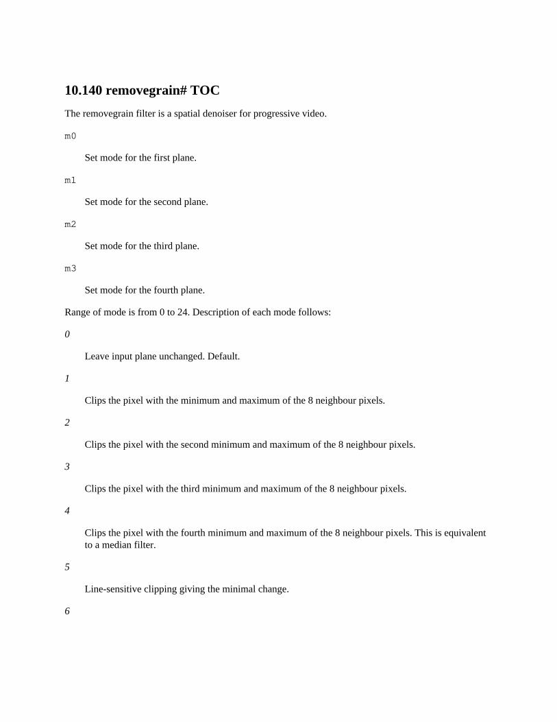
10.140 removegrain# TOC
The removegrain filter is a spatial denoiser for progressive video.
m0
Set mode for the first plane.
m1
Set mode for the second plane.
m2
Set mode for the third plane.
m3
Set mode for the fourth plane.
Range of mode is from 0 to 24. Description of each mode follows:
0
Leave input plane unchanged. Default.
1
Clips the pixel with the minimum and maximum of the 8 neighbour pixels.
2
Clips the pixel with the second minimum and maximum of the 8 neighbour pixels.
3
Clips the pixel with the third minimum and maximum of the 8 neighbour pixels.
4
Clips the pixel with the fourth minimum and maximum of the 8 neighbour pixels. This is equivalentto a median filter.
5
Line-sensitive clipping giving the minimal change.
6
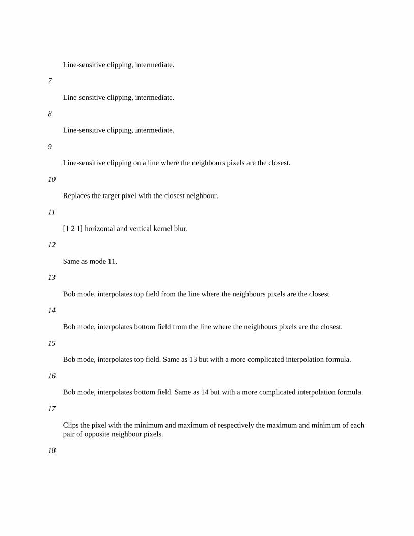
Line-sensitive clipping, intermediate.
7
Line-sensitive clipping, intermediate.
8
Line-sensitive clipping, intermediate.
9
Line-sensitive clipping on a line where the neighbours pixels are the closest.
10
Replaces the target pixel with the closest neighbour.
11
[1 2 1] horizontal and vertical kernel blur.
12
Same as mode 11.
13
Bob mode, interpolates top field from the line where the neighbours pixels are the closest.
14
Bob mode, interpolates bottom field from the line where the neighbours pixels are the closest.
15
Bob mode, interpolates top field. Same as 13 but with a more complicated interpolation formula.
16
Bob mode, interpolates bottom field. Same as 14 but with a more complicated interpolation formula.
17
Clips the pixel with the minimum and maximum of respectively the maximum and minimum of eachpair of opposite neighbour pixels.
18

Line-sensitive clipping using opposite neighbours whose greatest distance from the current pixel is minimal.
19
Replaces the pixel with the average of its 8 neighbours.
20
Averages the 9 pixels ([1 1 1] horizontal and vertical blur).
21
Clips pixels using the averages of opposite neighbour.
22
Same as mode 21 but simpler and faster.
23
Small edge and halo removal, but reputed useless.
24
Similar as 23.
10.141 removelogo# TOC
Suppress a TV station logo, using an image file to determine which pixels comprise the logo. It works byfilling in the pixels that comprise the logo with neighboring pixels.
The filter accepts the following options:
filename, f
Set the filter bitmap file, which can be any image format supported by libavformat. The width andheight of the image file must match those of the video stream being processed.
Pixels in the provided bitmap image with a value of zero are not considered part of the logo, non-zeropixels are considered part of the logo. If you use white (255) for the logo and black (0) for the rest, youwill be safe. For making the filter bitmap, it is recommended to take a screen capture of a black frame withthe logo visible, and then using a threshold filter followed by the erode filter once or twice.
If needed, little splotches can be fixed manually. Remember that if logo pixels are not covered, the filterquality will be much reduced. Marking too many pixels as part of the logo does not hurt as much, but itwill increase the amount of blurring needed to cover over the image and will destroy more informationthan necessary, and extra pixels will slow things down on a large logo.
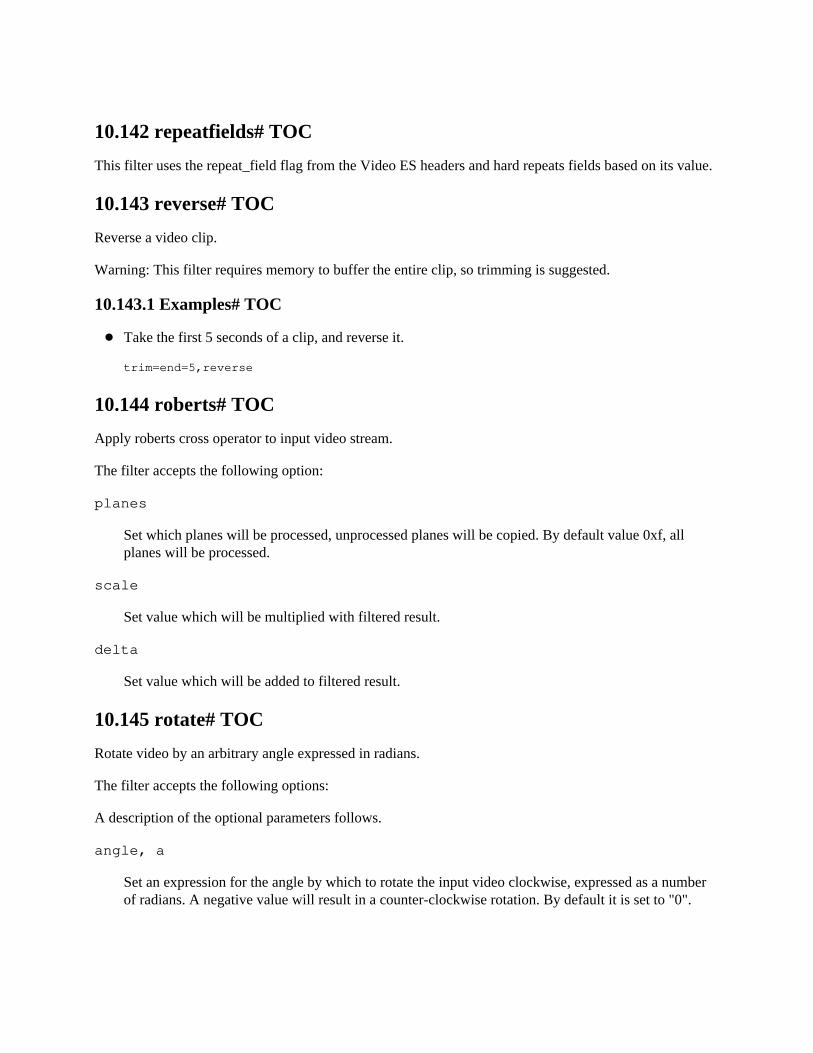
10.142 repeatfields# TOC
This filter uses the repeat_field flag from the Video ES headers and hard repeats fields based on its value.
10.143 reverse# TOC
Reverse a video clip.
Warning: This filter requires memory to buffer the entire clip, so trimming is suggested.
10.143.1 Examples# TOC
Take the first 5 seconds of a clip, and reverse it.
trim=end=5,reverse
10.144 roberts# TOC
Apply roberts cross operator to input video stream.
The filter accepts the following option:
planes
Set which planes will be processed, unprocessed planes will be copied. By default value 0xf, allplanes will be processed.
scale
Set value which will be multiplied with filtered result.
delta
Set value which will be added to filtered result.
10.145 rotate# TOC
Rotate video by an arbitrary angle expressed in radians.
The filter accepts the following options:
A description of the optional parameters follows.
angle, a
Set an expression for the angle by which to rotate the input video clockwise, expressed as a numberof radians. A negative value will result in a counter-clockwise rotation. By default it is set to "0".
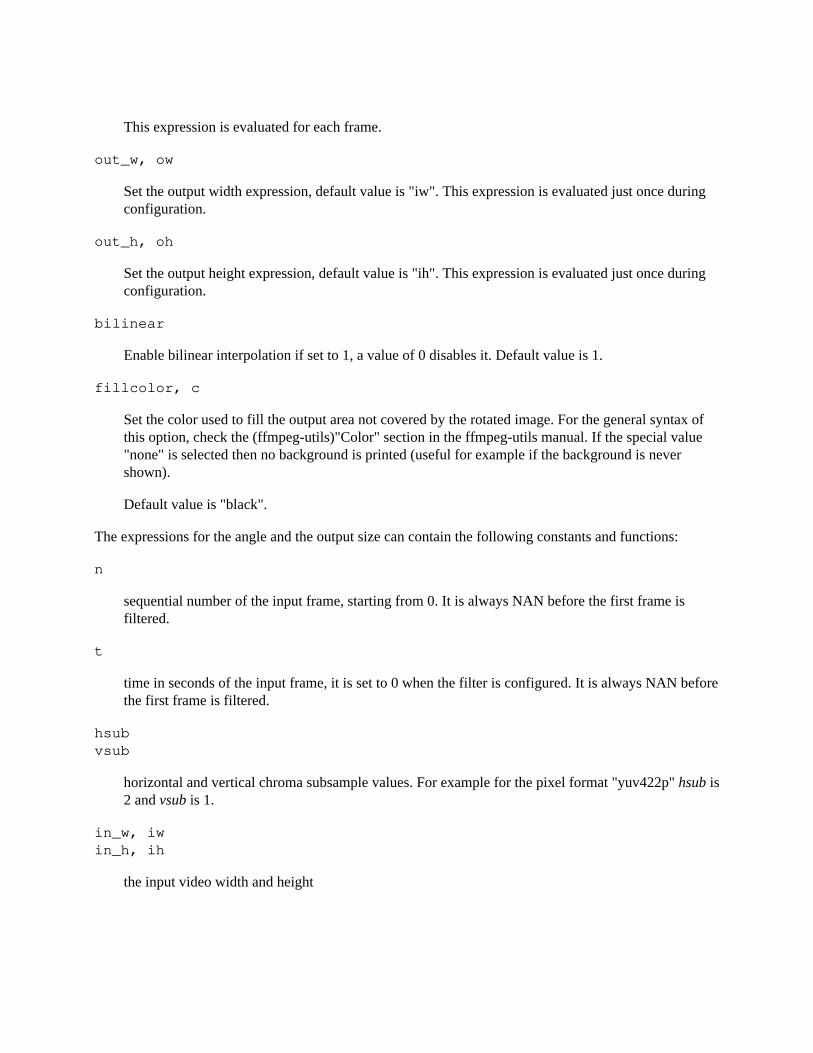
This expression is evaluated for each frame.
out_w, ow
Set the output width expression, default value is "iw". This expression is evaluated just once during configuration.
out_h, oh
Set the output height expression, default value is "ih". This expression is evaluated just once during configuration.
bilinear
Enable bilinear interpolation if set to 1, a value of 0 disables it. Default value is 1.
fillcolor, c
Set the color used to fill the output area not covered by the rotated image. For the general syntax ofthis option, check the (ffmpeg-utils)"Color" section in the ffmpeg-utils manual. If the special value"none" is selected then no background is printed (useful for example if the background is never shown).
Default value is "black".
The expressions for the angle and the output size can contain the following constants and functions:
n
sequential number of the input frame, starting from 0. It is always NAN before the first frame is filtered.
t
time in seconds of the input frame, it is set to 0 when the filter is configured. It is always NAN beforethe first frame is filtered.
hsub vsub
horizontal and vertical chroma subsample values. For example for the pixel format "yuv422p" hsub is2 and vsub is 1.
in_w, iw in_h, ih
the input video width and height
out_w, ow out_h, oh
the output width and height, that is the size of the padded area as specified by the width and height expressions
rotw(a) roth(a)
the minimal width/height required for completely containing the input video rotated by a radians.
These are only available when computing the out_w and out_h expressions.
10.145.1 Examples# TOC
Rotate the input by PI/6 radians clockwise:
rotate=PI/6
Rotate the input by PI/6 radians counter-clockwise:
rotate=-PI/6
Rotate the input by 45 degrees clockwise:
rotate=45*PI/180
Apply a constant rotation with period T, starting from an angle of PI/3:
rotate=PI/3+2*PI*t/T
Make the input video rotation oscillating with a period of T seconds and an amplitude of A radians:
rotate=A*sin(2*PI/T*t)
Rotate the video, output size is chosen so that the whole rotating input video is always completelycontained in the output:
rotate=’2*PI*t:ow=hypot(iw,ih):oh=ow’
Rotate the video, reduce the output size so that no background is ever shown:
rotate=2*PI*t:ow=’min(iw,ih)/sqrt(2)’:oh=ow:c=none
10.145.2 Commands# TOC
The filter supports the following commands:
a, angle
Set the angle expression. The command accepts the same syntax of the corresponding option.
If the specified expression is not valid, it is kept at its current value.
10.146 sab# TOC
Apply Shape Adaptive Blur.
The filter accepts the following options:
luma_radius, lr
Set luma blur filter strength, must be a value in range 0.1-4.0, default value is 1.0. A greater valuewill result in a more blurred image, and in slower processing.
luma_pre_filter_radius, lpfr
Set luma pre-filter radius, must be a value in the 0.1-2.0 range, default value is 1.0.
luma_strength, ls
Set luma maximum difference between pixels to still be considered, must be a value in the 0.1-100.0range, default value is 1.0.
chroma_radius, cr
Set chroma blur filter strength, must be a value in range -0.9-4.0. A greater value will result in a moreblurred image, and in slower processing.
chroma_pre_filter_radius, cpfr
Set chroma pre-filter radius, must be a value in the -0.9-2.0 range.
chroma_strength, cs
Set chroma maximum difference between pixels to still be considered, must be a value in the-0.9-100.0 range.
Each chroma option value, if not explicitly specified, is set to the corresponding luma option value.
10.147 scale# TOC
Scale (resize) the input video, using the libswscale library.
The scale filter forces the output display aspect ratio to be the same of the input, by changing the outputsample aspect ratio.
If the input image format is different from the format requested by the next filter, the scale filter willconvert the input to the requested format.
10.147.1 Options# TOC
The filter accepts the following options, or any of the options supported by the libswscale scaler.
See (ffmpeg-scaler)the ffmpeg-scaler manual for the complete list of scaler options.
width, w height, h
Set the output video dimension expression. Default value is the input dimension.
If the width or w value is 0, the input width is used for the output. If the height or h value is 0, theinput height is used for the output.
If one and only one of the values is -n with n >= 1, the scale filter will use a value that maintains theaspect ratio of the input image, calculated from the other specified dimension. After that it will,however, make sure that the calculated dimension is divisible by n and adjust the value if necessary.
If both values are -n with n >= 1, the behavior will be identical to both values being set to 0 aspreviously detailed.
See below for the list of accepted constants for use in the dimension expression.
eval
Specify when to evaluate width and height expression. It accepts the following values:
‘init’
Only evaluate expressions once during the filter initialization or when a command is processed.
‘frame’
Evaluate expressions for each incoming frame.
Default value is ‘init’.
interl
Set the interlacing mode. It accepts the following values:
‘1’
Force interlaced aware scaling.
‘0’
Do not apply interlaced scaling.
‘-1’
Select interlaced aware scaling depending on whether the source frames are flagged as interlacedor not.
Default value is ‘0’.
flags
Set libswscale scaling flags. See (ffmpeg-scaler)the ffmpeg-scaler manual for the complete list ofvalues. If not explicitly specified the filter applies the default flags.
param0, param1
Set libswscale input parameters for scaling algorithms that need them. See (ffmpeg-scaler)theffmpeg-scaler manual for the complete documentation. If not explicitly specified the filter appliesempty parameters.
size, s
Set the video size. For the syntax of this option, check the (ffmpeg-utils)"Video size" section in theffmpeg-utils manual.
in_color_matrix out_color_matrix
Set in/output YCbCr color space type.
This allows the autodetected value to be overridden as well as allows forcing a specific value used forthe output and encoder.
If not specified, the color space type depends on the pixel format.
Possible values:
‘auto’
Choose automatically.
‘bt709’
Format conforming to International Telecommunication Union (ITU) Recommendation BT.709.
‘fcc’
Set color space conforming to the United States Federal Communications Commission (FCC)Code of Federal Regulations (CFR) Title 47 (2003) 73.682 (a).
‘bt601’
Set color space conforming to:
ITU Radiocommunication Sector (ITU-R) Recommendation BT.601 ITU-R Rec. BT.470-6 (1998) Systems B, B1, and G Society of Motion Picture and Television Engineers (SMPTE) ST 170:2004
‘smpte240m’
Set color space conforming to SMPTE ST 240:1999.
in_range out_range
Set in/output YCbCr sample range.
This allows the autodetected value to be overridden as well as allows forcing a specific value used forthe output and encoder. If not specified, the range depends on the pixel format. Possible values:
‘auto/unknown’
Choose automatically.
‘jpeg/full/pc’
Set full range (0-255 in case of 8-bit luma).
‘mpeg/limited/tv’
Set "MPEG" range (16-235 in case of 8-bit luma).
force_original_aspect_ratio
Enable decreasing or increasing output video width or height if necessary to keep the original aspectratio. Possible values:
‘disable’
Scale the video as specified and disable this feature.
‘decrease’
The output video dimensions will automatically be decreased if needed.
‘increase’
The output video dimensions will automatically be increased if needed.
One useful instance of this option is that when you know a specific device’s maximum allowedresolution, you can use this to limit the output video to that, while retaining the aspect ratio. Forexample, device A allows 1280x720 playback, and your video is 1920x800. Using this option (set itto decrease) and specifying 1280x720 to the command line makes the output 1280x533.
Please note that this is a different thing than specifying -1 for w or h, you still need to specify theoutput resolution for this option to work.
The values of the w and h options are expressions containing the following constants:
in_w in_h
The input width and height
iw ih
These are the same as in_w and in_h.
out_w out_h
The output (scaled) width and height
ow oh
These are the same as out_w and out_h
a
The same as iw / ih
sar
input sample aspect ratio
dar
The input display aspect ratio. Calculated from (iw / ih) * sar.
hsub vsub
horizontal and vertical input chroma subsample values. For example for the pixel format "yuv422p" hsub is 2 and vsub is 1.
ohsub ovsub
horizontal and vertical output chroma subsample values. For example for the pixel format "yuv422p" hsub is 2 and vsub is 1.
10.147.2 Examples# TOC
Scale the input video to a size of 200x100
scale=w=200:h=100
This is equivalent to:
scale=200:100
or:
scale=200x100
Specify a size abbreviation for the output size:
scale=qcif
which can also be written as:
scale=size=qcif
Scale the input to 2x:
scale=w=2*iw:h=2*ih
The above is the same as:
scale=2*in_w:2*in_h
Scale the input to 2x with forced interlaced scaling:
scale=2*iw:2*ih:interl=1
Scale the input to half size:
scale=w=iw/2:h=ih/2
Increase the width, and set the height to the same size:
scale=3/2*iw:ow
Seek Greek harmony:
scale=iw:1/PHI*iwscale=ih*PHI:ih
Increase the height, and set the width to 3/2 of the height:
scale=w=3/2*oh:h=3/5*ih
Increase the size, making the size a multiple of the chroma subsample values:
scale="trunc(3/2*iw/hsub)*hsub:trunc(3/2*ih/vsub)*vsub"
Increase the width to a maximum of 500 pixels, keeping the same aspect ratio as the input:
scale=w=’min(500\, iw*3/2):h=-1’
Make pixels square by combining scale and setsar:
scale=’trunc(ih*dar):ih’,setsar=1/1
Make pixels square by combining scale and setsar, making sure the resulting resolution is even(required by some codecs):
scale=’trunc(ih*dar/2)*2:trunc(ih/2)*2’,setsar=1/1
10.147.3 Commands# TOC
This filter supports the following commands:
width, w height, h
Set the output video dimension expression. The command accepts the same syntax of thecorresponding option.
If the specified expression is not valid, it is kept at its current value.
10.148 scale_npp# TOC
Use the NVIDIA Performance Primitives (libnpp) to perform scaling and/or pixel format conversion onCUDA video frames. Setting the output width and height works in the same way as for the scale filter.
The following additional options are accepted:
format
The pixel format of the output CUDA frames. If set to the string "same" (the default), the inputformat will be kept. Note that automatic format negotiation and conversion is not yet supported forhardware frames
interp_algo

The interpolation algorithm used for resizing. One of the following:
nn
Nearest neighbour.
linear cubic cubic2p_bspline
2-parameter cubic (B=1, C=0)
cubic2p_catmullrom
2-parameter cubic (B=0, C=1/2)
cubic2p_b05c03
2-parameter cubic (B=1/2, C=3/10)
super
Supersampling
lanczos
10.149 scale2ref# TOC
Scale (resize) the input video, based on a reference video.
See the scale filter for available options, scale2ref supports the same but uses the reference video insteadof the main input as basis. scale2ref also supports the following additional constants for the w and h options:
main_w main_h
The main input video’s width and height
main_a
The same as main_w / main_h
main_sar
The main input video’s sample aspect ratio
main_dar, mdar
The main input video’s display aspect ratio. Calculated from (main_w / main_h) * main_sar.
main_hsub main_vsub
The main input video’s horizontal and vertical chroma subsample values. For example for the pixelformat "yuv422p" hsub is 2 and vsub is 1.
10.149.1 Examples# TOC
Scale a subtitle stream (b) to match the main video (a) in size before overlaying
’scale2ref[b][a];[a][b]overlay’
10.150 selectivecolor# TOC
Adjust cyan, magenta, yellow and black (CMYK) to certain ranges of colors (such as "reds", "yellows","greens", "cyans", ...). The adjustment range is defined by the "purity" of the color (that is, how saturatedit already is).
This filter is similar to the Adobe Photoshop Selective Color tool.
The filter accepts the following options:
correction_method
Select color correction method.
Available values are:
‘absolute’
Specified adjustments are applied "as-is" (added/subtracted to original pixel component value).
‘relative’
Specified adjustments are relative to the original component value.
Default is absolute.
reds
Adjustments for red pixels (pixels where the red component is the maximum)
yellows
Adjustments for yellow pixels (pixels where the blue component is the minimum)
greens
Adjustments for green pixels (pixels where the green component is the maximum)
cyans
Adjustments for cyan pixels (pixels where the red component is the minimum)
blues
Adjustments for blue pixels (pixels where the blue component is the maximum)
magentas
Adjustments for magenta pixels (pixels where the green component is the minimum)
whites
Adjustments for white pixels (pixels where all components are greater than 128)
neutrals
Adjustments for all pixels except pure black and pure white
blacks
Adjustments for black pixels (pixels where all components are lesser than 128)
psfile
Specify a Photoshop selective color file (.asv) to import the settings from.
All the adjustment settings (reds, yellows, ...) accept up to 4 space separated floating point adjustmentvalues in the [-1,1] range, respectively to adjust the amount of cyan, magenta, yellow and black for thepixels of its range.
10.150.1 Examples# TOC
Increase cyan by 50% and reduce yellow by 33% in every green areas, and increase magenta by 27%in blue areas:
selectivecolor=greens=.5 0 -.33 0:blues=0 .27
Use a Photoshop selective color preset:
selectivecolor=psfile=MySelectiveColorPresets/Misty.asv
10.151 separatefields# TOC
The separatefields takes a frame-based video input and splits each frame into its components fields,producing a new half height clip with twice the frame rate and twice the frame count.
This filter use field-dominance information in frame to decide which of each pair of fields to place first inthe output. If it gets it wrong use setfield filter before separatefields filter.
10.152 setdar, setsar# TOC
The setdar filter sets the Display Aspect Ratio for the filter output video.
This is done by changing the specified Sample (aka Pixel) Aspect Ratio, according to the following equation:
DAR = HORIZONTAL_RESOLUTION / VERTICAL_RESOLUTION * SAR
Keep in mind that the setdar filter does not modify the pixel dimensions of the video frame. Also, thedisplay aspect ratio set by this filter may be changed by later filters in the filterchain, e.g. in case of scalingor if another "setdar" or a "setsar" filter is applied.
The setsar filter sets the Sample (aka Pixel) Aspect Ratio for the filter output video.
Note that as a consequence of the application of this filter, the output display aspect ratio will changeaccording to the equation above.
Keep in mind that the sample aspect ratio set by the setsar filter may be changed by later filters in thefilterchain, e.g. if another "setsar" or a "setdar" filter is applied.
It accepts the following parameters:
r, ratio, dar (setdar only), sar (setsar only)
Set the aspect ratio used by the filter.
The parameter can be a floating point number string, an expression, or a string of the form num:den,where num and den are the numerator and denominator of the aspect ratio. If the parameter is notspecified, it is assumed the value "0". In case the form "num:den" is used, the : character should be escaped.
max
Set the maximum integer value to use for expressing numerator and denominator when reducing theexpressed aspect ratio to a rational. Default value is 100.
The parameter sar is an expression containing the following constants:
E, PI, PHI
These are approximated values for the mathematical constants e (Euler’s number), pi (Greek pi), andphi (the golden ratio).
w, h
The input width and height.
a
These are the same as w / h.
sar
The input sample aspect ratio.
dar
The input display aspect ratio. It is the same as (w / h) * sar.
hsub, vsub
Horizontal and vertical chroma subsample values. For example, for the pixel format "yuv422p" hsubis 2 and vsub is 1.
10.152.1 Examples# TOC
To change the display aspect ratio to 16:9, specify one of the following:
setdar=dar=1.77777setdar=dar=16/9
To change the sample aspect ratio to 10:11, specify:
setsar=sar=10/11
To set a display aspect ratio of 16:9, and specify a maximum integer value of 1000 in the aspect ratioreduction, use the command:
setdar=ratio=16/9:max=1000
10.153 setfield# TOC
Force field for the output video frame.
The setfield filter marks the interlace type field for the output frames. It does not change the inputframe, but only sets the corresponding property, which affects how the frame is treated by following filters(e.g. fieldorder or yadif).
The filter accepts the following options:
mode
Available values are:
‘auto’
Keep the same field property.
‘bff’
Mark the frame as bottom-field-first.
‘tff’
Mark the frame as top-field-first.
‘prog’
Mark the frame as progressive.
10.154 showinfo# TOC
Show a line containing various information for each input video frame. The input video is not modified.
The shown line contains a sequence of key/value pairs of the form key:value.
The following values are shown in the output:
n
The (sequential) number of the input frame, starting from 0.
pts
The Presentation TimeStamp of the input frame, expressed as a number of time base units. The timebase unit depends on the filter input pad.
pts_time
The Presentation TimeStamp of the input frame, expressed as a number of seconds.
pos
The position of the frame in the input stream, or -1 if this information is unavailable and/ormeaningless (for example in case of synthetic video).
fmt
The pixel format name.
sar
The sample aspect ratio of the input frame, expressed in the form num/den.
s
The size of the input frame. For the syntax of this option, check the (ffmpeg-utils)"Video size"section in the ffmpeg-utils manual.
i
The type of interlaced mode ("P" for "progressive", "T" for top field first, "B" for bottom field first).
iskey
This is 1 if the frame is a key frame, 0 otherwise.
type
The picture type of the input frame ("I" for an I-frame, "P" for a P-frame, "B" for a B-frame, or "?"for an unknown type). Also refer to the documentation of the AVPictureType enum and of the av_get_picture_type_char function defined in libavutil/avutil.h.
checksum
The Adler-32 checksum (printed in hexadecimal) of all the planes of the input frame.
plane_checksum
The Adler-32 checksum (printed in hexadecimal) of each plane of the input frame, expressed in theform "[c0 c1 c2 c3]".
10.155 showpalette# TOC
Displays the 256 colors palette of each frame. This filter is only relevant for pal8 pixel format frames.
It accepts the following option:
s
Set the size of the box used to represent one palette color entry. Default is 30 (for a 30x30 pixel box).
10.156 shuffleframes# TOC
Reorder and/or duplicate and/or drop video frames.
It accepts the following parameters:
mapping
Set the destination indexes of input frames. This is space or ’|’ separated list of indexes that mapsinput frames to output frames. Number of indexes also sets maximal value that each index may have.’-1’ index have special meaning and that is to drop frame.
The first frame has the index 0. The default is to keep the input unchanged.
10.156.1 Examples# TOC
Swap second and third frame of every three frames of the input:
ffmpeg -i INPUT -vf "shuffleframes=0 2 1" OUTPUT
Swap 10th and 1st frame of every ten frames of the input:
ffmpeg -i INPUT -vf "shuffleframes=9 1 2 3 4 5 6 7 8 0" OUTPUT
10.157 shuffleplanes# TOC
Reorder and/or duplicate video planes.
It accepts the following parameters:
map0
The index of the input plane to be used as the first output plane.
map1
The index of the input plane to be used as the second output plane.
map2
The index of the input plane to be used as the third output plane.
map3
The index of the input plane to be used as the fourth output plane.
The first plane has the index 0. The default is to keep the input unchanged.
10.157.1 Examples# TOC
Swap the second and third planes of the input:
ffmpeg -i INPUT -vf shuffleplanes=0:2:1:3 OUTPUT
10.158 signalstats# TOC
Evaluate various visual metrics that assist in determining issues associated with the digitization of analogvideo media.
By default the filter will log these metadata values:
YMIN
Display the minimal Y value contained within the input frame. Expressed in range of [0-255].
YLOW
Display the Y value at the 10% percentile within the input frame. Expressed in range of [0-255].
YAVG
Display the average Y value within the input frame. Expressed in range of [0-255].
YHIGH
Display the Y value at the 90% percentile within the input frame. Expressed in range of [0-255].
YMAX
Display the maximum Y value contained within the input frame. Expressed in range of [0-255].
UMIN
Display the minimal U value contained within the input frame. Expressed in range of [0-255].
ULOW
Display the U value at the 10% percentile within the input frame. Expressed in range of [0-255].
UAVG
Display the average U value within the input frame. Expressed in range of [0-255].
UHIGH
Display the U value at the 90% percentile within the input frame. Expressed in range of [0-255].
UMAX
Display the maximum U value contained within the input frame. Expressed in range of [0-255].
VMIN
Display the minimal V value contained within the input frame. Expressed in range of [0-255].
VLOW
Display the V value at the 10% percentile within the input frame. Expressed in range of [0-255].
VAVG
Display the average V value within the input frame. Expressed in range of [0-255].
VHIGH
Display the V value at the 90% percentile within the input frame. Expressed in range of [0-255].
VMAX
Display the maximum V value contained within the input frame. Expressed in range of [0-255].
SATMIN
Display the minimal saturation value contained within the input frame. Expressed in range of [0-~181.02].
SATLOW
Display the saturation value at the 10% percentile within the input frame. Expressed in range of [0-~181.02].
SATAVG
Display the average saturation value within the input frame. Expressed in range of [0-~181.02].
SATHIGH
Display the saturation value at the 90% percentile within the input frame. Expressed in range of [0-~181.02].
SATMAX
Display the maximum saturation value contained within the input frame. Expressed in range of [0-~181.02].
HUEMED
Display the median value for hue within the input frame. Expressed in range of [0-360].
HUEAVG
Display the average value for hue within the input frame. Expressed in range of [0-360].
YDIF
Display the average of sample value difference between all values of the Y plane in the current frameand corresponding values of the previous input frame. Expressed in range of [0-255].
UDIF
Display the average of sample value difference between all values of the U plane in the current frameand corresponding values of the previous input frame. Expressed in range of [0-255].
VDIF
Display the average of sample value difference between all values of the V plane in the current frameand corresponding values of the previous input frame. Expressed in range of [0-255].
YBITDEPTH
Display bit depth of Y plane in current frame. Expressed in range of [0-16].
UBITDEPTH
Display bit depth of U plane in current frame. Expressed in range of [0-16].
VBITDEPTH
Display bit depth of V plane in current frame. Expressed in range of [0-16].
The filter accepts the following options:
stat out
stat specify an additional form of image analysis. out output video with the specified type of pixel highlighted.
Both options accept the following values:
‘tout’
Identify temporal outliers pixels. A temporal outlier is a pixel unlike the neighboring pixels ofthe same field. Examples of temporal outliers include the results of video dropouts, head clogs,or tape tracking issues.
‘vrep’
Identify vertical line repetition. Vertical line repetition includes similar rows of pixels within aframe. In born-digital video vertical line repetition is common, but this pattern is uncommon invideo digitized from an analog source. When it occurs in video that results from the digitizationof an analog source it can indicate concealment from a dropout compensator.
‘brng’
Identify pixels that fall outside of legal broadcast range.
color, c
Set the highlight color for the out option. The default color is yellow.
10.158.1 Examples# TOC
Output data of various video metrics:
ffprobe -f lavfi movie=example.mov,signalstats="stat=tout+vrep+brng" -show_frames
Output specific data about the minimum and maximum values of the Y plane per frame:
ffprobe -f lavfi movie=example.mov,signalstats -show_entries frame_tags=lavfi.signalstats.YMAX,lavfi.signalstats.YMIN
Playback video while highlighting pixels that are outside of broadcast range in red.
ffplay example.mov -vf signalstats="out=brng:color=red"
Playback video with signalstats metadata drawn over the frame.
ffplay example.mov -vf signalstats=stat=brng+vrep+tout,drawtext=fontfile=FreeSerif.ttf:textfile=signalstat_drawtext.txt
The contents of signalstat_drawtext.txt used in the command are:
time %{pts:hms}Y (%{metadata:lavfi.signalstats.YMIN}-%{metadata:lavfi.signalstats.YMAX})U (%{metadata:lavfi.signalstats.UMIN}-%{metadata:lavfi.signalstats.UMAX})V (%{metadata:lavfi.signalstats.VMIN}-%{metadata:lavfi.signalstats.VMAX})saturation maximum: %{metadata:lavfi.signalstats.SATMAX}
10.159 signature# TOC
Calculates the MPEG-7 Video Signature. The filter can handle more than one input. In this case thematching between the inputs can be calculated additionally. The filter always passes through the firstinput. The signature of each stream can be written into a file.
It accepts the following options:
detectmode
Enable or disable the matching process.
Available values are:
‘off’
Disable the calculation of a matching (default).
‘full’
Calculate the matching for the whole video and output whether the whole video matches or only parts.
‘fast’
Calculate only until a matching is found or the video ends. Should be faster in some cases.
nb_inputs
Set the number of inputs. The option value must be a non negative integer. Default value is 1.
filename
Set the path to which the output is written. If there is more than one input, the path must be aprototype, i.e. must contain %d or %0nd (where n is a positive integer), that will be replaced with theinput number. If no filename is specified, no output will be written. This is the default.
format
Choose the output format.
Available values are:
‘binary’
Use the specified binary representation (default).
‘xml’
Use the specified xml representation.
th_d
Set threshold to detect one word as similar. The option value must be an integer greater than zero.The default value is 9000.
th_dc
Set threshold to detect all words as similar. The option value must be an integer greater than zero.The default value is 60000.
th_xh
Set threshold to detect frames as similar. The option value must be an integer greater than zero. Thedefault value is 116.
th_di
Set the minimum length of a sequence in frames to recognize it as matching sequence. The optionvalue must be a non negative integer value. The default value is 0.
th_it
Set the minimum relation, that matching frames to all frames must have. The option value must be adouble value between 0 and 1. The default value is 0.5.
10.159.1 Examples# TOC
To calculate the signature of an input video and store it in signature.bin:
ffmpeg -i input.mkv -vf signature=filename=signature.bin -map 0:v -f null -
To detect whether two videos match and store the signatures in XML format in signature0.xml andsignature1.xml:
ffmpeg -i input1.mkv -i input2.mkv -filter_complex "[0:v][1:v] signature=nb_inputs=2:detectmode=full:format=xml:filename=signature%d.xml" -map :v -f null -
10.160 smartblur# TOC
Blur the input video without impacting the outlines.
It accepts the following options:
luma_radius, lr
Set the luma radius. The option value must be a float number in the range [0.1,5.0] that specifies thevariance of the gaussian filter used to blur the image (slower if larger). Default value is 1.0.
luma_strength, ls
Set the luma strength. The option value must be a float number in the range [-1.0,1.0] that configuresthe blurring. A value included in [0.0,1.0] will blur the image whereas a value included in [-1.0,0.0]will sharpen the image. Default value is 1.0.
luma_threshold, lt
Set the luma threshold used as a coefficient to determine whether a pixel should be blurred or not.The option value must be an integer in the range [-30,30]. A value of 0 will filter all the image, avalue included in [0,30] will filter flat areas and a value included in [-30,0] will filter edges. Defaultvalue is 0.
chroma_radius, cr
Set the chroma radius. The option value must be a float number in the range [0.1,5.0] that specifiesthe variance of the gaussian filter used to blur the image (slower if larger). Default value is luma_radius.
chroma_strength, cs
Set the chroma strength. The option value must be a float number in the range [-1.0,1.0] thatconfigures the blurring. A value included in [0.0,1.0] will blur the image whereas a value included in[-1.0,0.0] will sharpen the image. Default value is luma_strength.
chroma_threshold, ct
Set the chroma threshold used as a coefficient to determine whether a pixel should be blurred or not.The option value must be an integer in the range [-30,30]. A value of 0 will filter all the image, avalue included in [0,30] will filter flat areas and a value included in [-30,0] will filter edges. Defaultvalue is luma_threshold.
If a chroma option is not explicitly set, the corresponding luma value is set.
10.161 ssim# TOC
Obtain the SSIM (Structural SImilarity Metric) between two input videos.
This filter takes in input two input videos, the first input is considered the "main" source and is passedunchanged to the output. The second input is used as a "reference" video for computing the SSIM.
Both video inputs must have the same resolution and pixel format for this filter to work correctly. Also itassumes that both inputs have the same number of frames, which are compared one by one.
The filter stores the calculated SSIM of each frame.
The description of the accepted parameters follows.
stats_file, f
If specified the filter will use the named file to save the SSIM of each individual frame. Whenfilename equals "-" the data is sent to standard output.
The file printed if stats_file is selected, contains a sequence of key/value pairs of the form key:value foreach compared couple of frames.
A description of each shown parameter follows:
n
sequential number of the input frame, starting from 1
Y, U, V, R, G, B
SSIM of the compared frames for the component specified by the suffix.
All
SSIM of the compared frames for the whole frame.
dB
Same as above but in dB representation.
This filter also supports the framesync options.
For example:
movie=ref_movie.mpg, setpts=PTS-STARTPTS [main];[main][ref] ssim="stats_file=stats.log" [out]
On this example the input file being processed is compared with the reference file ref_movie.mpg.The SSIM of each individual frame is stored in stats.log.
Another example with both psnr and ssim at same time:
ffmpeg -i main.mpg -i ref.mpg -lavfi "ssim;[0:v][1:v]psnr" -f null -
10.162 stereo3d# TOC
Convert between different stereoscopic image formats.
The filters accept the following options:
in
Set stereoscopic image format of input.
Available values for input image formats are:
‘sbsl’
side by side parallel (left eye left, right eye right)
‘sbsr’
side by side crosseye (right eye left, left eye right)
‘sbs2l’
side by side parallel with half width resolution (left eye left, right eye right)
‘sbs2r’
side by side crosseye with half width resolution (right eye left, left eye right)
‘abl’
above-below (left eye above, right eye below)
‘abr’
above-below (right eye above, left eye below)
‘ab2l’
above-below with half height resolution (left eye above, right eye below)
‘ab2r’
above-below with half height resolution (right eye above, left eye below)
‘al’
alternating frames (left eye first, right eye second)
‘ar’
alternating frames (right eye first, left eye second)
‘irl’
interleaved rows (left eye has top row, right eye starts on next row)
‘irr’
interleaved rows (right eye has top row, left eye starts on next row)
‘icl’
interleaved columns, left eye first
‘icr’
interleaved columns, right eye first
Default value is ‘sbsl’.
out
Set stereoscopic image format of output.
‘sbsl’
side by side parallel (left eye left, right eye right)
‘sbsr’
side by side crosseye (right eye left, left eye right)
‘sbs2l’
side by side parallel with half width resolution (left eye left, right eye right)
‘sbs2r’
side by side crosseye with half width resolution (right eye left, left eye right)
‘abl’
above-below (left eye above, right eye below)
‘abr’
above-below (right eye above, left eye below)
‘ab2l’
above-below with half height resolution (left eye above, right eye below)
‘ab2r’
above-below with half height resolution (right eye above, left eye below)
‘al’
alternating frames (left eye first, right eye second)
‘ar’
alternating frames (right eye first, left eye second)
‘irl’
interleaved rows (left eye has top row, right eye starts on next row)
‘irr’
interleaved rows (right eye has top row, left eye starts on next row)
‘arbg’
anaglyph red/blue gray (red filter on left eye, blue filter on right eye)
‘argg’
anaglyph red/green gray (red filter on left eye, green filter on right eye)
‘arcg’
anaglyph red/cyan gray (red filter on left eye, cyan filter on right eye)
‘arch’
anaglyph red/cyan half colored (red filter on left eye, cyan filter on right eye)
‘arcc’
anaglyph red/cyan color (red filter on left eye, cyan filter on right eye)
‘arcd’
anaglyph red/cyan color optimized with the least squares projection of dubois (red filter on lefteye, cyan filter on right eye)
‘agmg’
anaglyph green/magenta gray (green filter on left eye, magenta filter on right eye)
‘agmh’
anaglyph green/magenta half colored (green filter on left eye, magenta filter on right eye)
‘agmc’
anaglyph green/magenta colored (green filter on left eye, magenta filter on right eye)
‘agmd’
anaglyph green/magenta color optimized with the least squares projection of dubois (green filteron left eye, magenta filter on right eye)
‘aybg’
anaglyph yellow/blue gray (yellow filter on left eye, blue filter on right eye)
‘aybh’
anaglyph yellow/blue half colored (yellow filter on left eye, blue filter on right eye)
‘aybc’
anaglyph yellow/blue colored (yellow filter on left eye, blue filter on right eye)
‘aybd’
anaglyph yellow/blue color optimized with the least squares projection of dubois (yellow filteron left eye, blue filter on right eye)
‘ml’
mono output (left eye only)
‘mr’
mono output (right eye only)
‘chl’
checkerboard, left eye first
‘chr’
checkerboard, right eye first
‘icl’
interleaved columns, left eye first
‘icr’
interleaved columns, right eye first
‘hdmi’
HDMI frame pack
Default value is ‘arcd’.
10.162.1 Examples# TOC
Convert input video from side by side parallel to anaglyph yellow/blue dubois:
stereo3d=sbsl:aybd
Convert input video from above below (left eye above, right eye below) to side by side crosseye.
stereo3d=abl:sbsr
10.163 streamselect, astreamselect# TOC
Select video or audio streams.
The filter accepts the following options:
inputs
Set number of inputs. Default is 2.
map
Set input indexes to remap to outputs.
10.163.1 Commands# TOC
The streamselect and astreamselect filter supports the following commands:
map
Set input indexes to remap to outputs.
10.163.2 Examples# TOC
Select first 5 seconds 1st stream and rest of time 2nd stream:
sendcmd=’5.0 streamselect map 1’,streamselect=inputs=2:map=0
Same as above, but for audio:
asendcmd=’5.0 astreamselect map 1’,astreamselect=inputs=2:map=0
10.164 sobel# TOC
Apply sobel operator to input video stream.
The filter accepts the following option:
planes
Set which planes will be processed, unprocessed planes will be copied. By default value 0xf, allplanes will be processed.
scale
Set value which will be multiplied with filtered result.
delta
Set value which will be added to filtered result.
10.165 spp# TOC
Apply a simple postprocessing filter that compresses and decompresses the image at several (or - in thecase of quality level 6 - all) shifts and average the results.
The filter accepts the following options:
quality
Set quality. This option defines the number of levels for averaging. It accepts an integer in the range0-6. If set to 0, the filter will have no effect. A value of 6 means the higher quality. For eachincrement of that value the speed drops by a factor of approximately 2. Default value is 3.
qp
Force a constant quantization parameter. If not set, the filter will use the QP from the video stream (if available).
mode
Set thresholding mode. Available modes are:
‘hard’
Set hard thresholding (default).
‘soft’
Set soft thresholding (better de-ringing effect, but likely blurrier).
use_bframe_qp
Enable the use of the QP from the B-Frames if set to 1. Using this option may cause flicker since theB-Frames have often larger QP. Default is 0 (not enabled).
10.166 subtitles# TOC
Draw subtitles on top of input video using the libass library.
To enable compilation of this filter you need to configure FFmpeg with --enable-libass. This filteralso requires a build with libavcodec and libavformat to convert the passed subtitles file to ASS(Advanced Substation Alpha) subtitles format.
The filter accepts the following options:
filename, f
Set the filename of the subtitle file to read. It must be specified.
original_size
Specify the size of the original video, the video for which the ASS file was composed. For the syntaxof this option, check the (ffmpeg-utils)"Video size" section in the ffmpeg-utils manual. Due to amisdesign in ASS aspect ratio arithmetic, this is necessary to correctly scale the fonts if the aspectratio has been changed.
fontsdir
Set a directory path containing fonts that can be used by the filter. These fonts will be used inaddition to whatever the font provider uses.
alpha
Process alpha channel, by default alpha channel is untouched.
charenc
Set subtitles input character encoding. subtitles filter only. Only useful if not UTF-8.
stream_index, si
Set subtitles stream index. subtitles filter only.
force_style
Override default style or script info parameters of the subtitles. It accepts a string containing ASSstyle format KEY=VALUE couples separated by ",".
If the first key is not specified, it is assumed that the first value specifies the filename.
For example, to render the file sub.srt on top of the input video, use the command:
subtitles=sub.srt
which is equivalent to:
subtitles=filename=sub.srt
To render the default subtitles stream from file video.mkv, use:
subtitles=video.mkv
To render the second subtitles stream from that file, use:
subtitles=video.mkv:si=1
To make the subtitles stream from sub.srt appear in transparent green DejaVu Serif, use:
subtitles=sub.srt:force_style=’FontName=DejaVu Serif,PrimaryColour=&HAA00FF00’
10.167 super2xsai# TOC
Scale the input by 2x and smooth using the Super2xSaI (Scale and Interpolate) pixel art scaling algorithm.
Useful for enlarging pixel art images without reducing sharpness.
10.168 swaprect# TOC
Swap two rectangular objects in video.
This filter accepts the following options:
w
Set object width.
h
Set object height.
x1
Set 1st rect x coordinate.
y1
Set 1st rect y coordinate.
x2
Set 2nd rect x coordinate.
y2
Set 2nd rect y coordinate.
All expressions are evaluated once for each frame.
The all options are expressions containing the following constants:
w h
The input width and height.
a
same as w / h
sar
input sample aspect ratio
dar
input display aspect ratio, it is the same as (w / h) * sar
n
The number of the input frame, starting from 0.
t
The timestamp expressed in seconds. It’s NAN if the input timestamp is unknown.
pos
the position in the file of the input frame, NAN if unknown
10.169 swapuv# TOC
Swap U & V plane.
10.170 telecine# TOC
Apply telecine process to the video.
This filter accepts the following options:
first_field ‘top, t’
top field first
‘bottom, b’
bottom field first The default value is top.
pattern
A string of numbers representing the pulldown pattern you wish to apply. The default value is 23.
Some typical patterns:
NTSC output (30i):27.5p: 3222224p: 23 (classic)24p: 2332 (preferred)20p: 3318p: 33416p: 3444
PAL output (25i):27.5p: 1222224p: 222222222223 ("Euro pulldown")16.67p: 3316p: 33333334
10.171 threshold# TOC
Apply threshold effect to video stream.
This filter needs four video streams to perform thresholding. First stream is stream we are filtering.Second stream is holding threshold values, third stream is holding min values, and last, fourth stream isholding max values.
The filter accepts the following option:
planes
Set which planes will be processed, unprocessed planes will be copied. By default value 0xf, allplanes will be processed.
For example if first stream pixel’s component value is less then threshold value of pixel component from2nd threshold stream, third stream value will picked, otherwise fourth stream pixel component value willbe picked.
Using color source filter one can perform various types of thresholding:
10.171.1 Examples# TOC
Binary threshold, using gray color as threshold:
ffmpeg -i 320x240.avi -f lavfi -i color=gray -f lavfi -i color=black -f lavfi -i color=white -lavfi threshold output.avi
Inverted binary threshold, using gray color as threshold:
ffmpeg -i 320x240.avi -f lavfi -i color=gray -f lavfi -i color=white -f lavfi -i color=black -lavfi threshold output.avi
Truncate binary threshold, using gray color as threshold:
ffmpeg -i 320x240.avi -f lavfi -i color=gray -i 320x240.avi -f lavfi -i color=gray -lavfi threshold output.avi
Threshold to zero, using gray color as threshold:
ffmpeg -i 320x240.avi -f lavfi -i color=gray -f lavfi -i color=white -i 320x240.avi -lavfi threshold output.avi
Inverted threshold to zero, using gray color as threshold:
ffmpeg -i 320x240.avi -f lavfi -i color=gray -i 320x240.avi -f lavfi -i color=white -lavfi threshold output.avi
10.172 thumbnail# TOC
Select the most representative frame in a given sequence of consecutive frames.
The filter accepts the following options:
n
Set the frames batch size to analyze; in a set of n frames, the filter will pick one of them, and thenhandle the next batch of n frames until the end. Default is 100.
Since the filter keeps track of the whole frames sequence, a bigger n value will result in a higher memoryusage, so a high value is not recommended.
10.172.1 Examples# TOC
Extract one picture each 50 frames:
thumbnail=50
Complete example of a thumbnail creation with ffmpeg:
ffmpeg -i in.avi -vf thumbnail,scale=300:200 -frames:v 1 out.png
10.173 tile# TOC
Tile several successive frames together.
The filter accepts the following options:
layout
Set the grid size (i.e. the number of lines and columns). For the syntax of this option, check the (ffmpeg-utils)"Video size" section in the ffmpeg-utils manual.
nb_frames
Set the maximum number of frames to render in the given area. It must be less than or equal to wxh.The default value is 0, meaning all the area will be used.
margin
Set the outer border margin in pixels.
padding
Set the inner border thickness (i.e. the number of pixels between frames). For more advanced paddingoptions (such as having different values for the edges), refer to the pad video filter.
color
Specify the color of the unused area. For the syntax of this option, check the (ffmpeg-utils)"Color"section in the ffmpeg-utils manual. The default value of color is "black".
overlap
Set the number of frames to overlap when tiling several successive frames together. The value mustbe between 0 and nb_frames - 1.
init_padding
Set the number of frames to initially be empty before displaying first output frame. This controls howsoon will one get first output frame. The value must be between 0 and nb_frames - 1.
10.173.1 Examples# TOC
Produce 8x8 PNG tiles of all keyframes (-skip_frame nokey) in a movie:
ffmpeg -skip_frame nokey -i file.avi -vf ’scale=128:72,tile=8x8’ -an -vsync 0 keyframes%03d.png
The -vsync 0 is necessary to prevent ffmpeg from duplicating each output frame toaccommodate the originally detected frame rate.
Display 5 pictures in an area of 3x2 frames, with 7 pixels between them, and 2 pixels of initialmargin, using mixed flat and named options:
tile=3x2:nb_frames=5:padding=7:margin=2
10.174 tinterlace# TOC
Perform various types of temporal field interlacing.
Frames are counted starting from 1, so the first input frame is considered odd.
The filter accepts the following options:
mode
Specify the mode of the interlacing. This option can also be specified as a value alone. See below fora list of values for this option.
Available values are:
‘merge, 0’
Move odd frames into the upper field, even into the lower field, generating a double heightframe at half frame rate.
------> timeInput:Frame 1 Frame 2 Frame 3 Frame 4
11111 22222 33333 4444411111 22222 33333 4444411111 22222 33333 4444411111 22222 33333 44444
Output:11111 3333322222 4444411111 3333322222 4444411111 3333322222 4444411111 3333322222 44444
‘drop_even, 1’
Only output odd frames, even frames are dropped, generating a frame with unchanged height athalf frame rate.
------> timeInput:Frame 1 Frame 2 Frame 3 Frame 4

11111 22222 33333 4444411111 22222 33333 4444411111 22222 33333 4444411111 22222 33333 44444
Output:11111 3333311111 3333311111 3333311111 33333
‘drop_odd, 2’
Only output even frames, odd frames are dropped, generating a frame with unchanged height athalf frame rate.
------> timeInput:Frame 1 Frame 2 Frame 3 Frame 4
11111 22222 33333 4444411111 22222 33333 4444411111 22222 33333 4444411111 22222 33333 44444
Output: 22222 44444 22222 44444 22222 44444 22222 44444
‘pad, 3’
Expand each frame to full height, but pad alternate lines with black, generating a frame withdouble height at the same input frame rate.
------> timeInput:Frame 1 Frame 2 Frame 3 Frame 4
11111 22222 33333 4444411111 22222 33333 4444411111 22222 33333 4444411111 22222 33333 44444
Output:11111 ..... 33333 .......... 22222 ..... 4444411111 ..... 33333 .......... 22222 ..... 4444411111 ..... 33333 .......... 22222 ..... 4444411111 ..... 33333 .......... 22222 ..... 44444
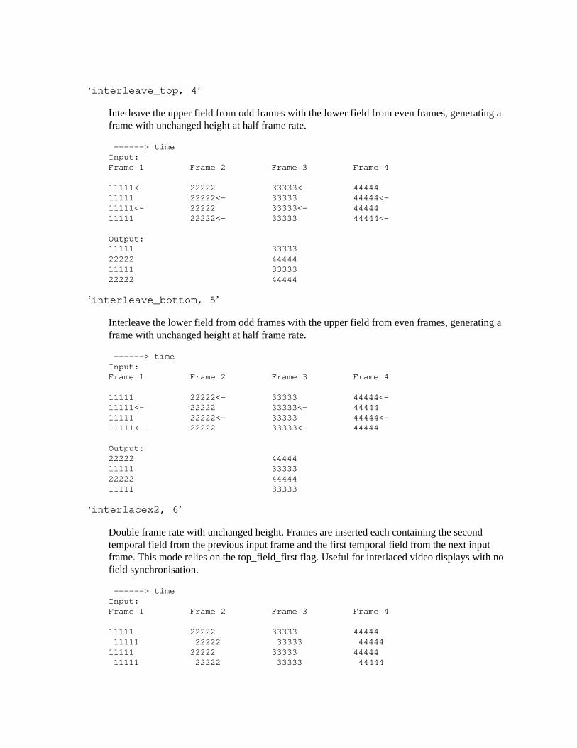
‘interleave_top, 4’
Interleave the upper field from odd frames with the lower field from even frames, generating aframe with unchanged height at half frame rate.
------> timeInput:Frame 1 Frame 2 Frame 3 Frame 4
11111<- 22222 33333<- 4444411111 22222<- 33333 44444<-11111<- 22222 33333<- 4444411111 22222<- 33333 44444<-
Output:11111 3333322222 4444411111 3333322222 44444
‘interleave_bottom, 5’
Interleave the lower field from odd frames with the upper field from even frames, generating aframe with unchanged height at half frame rate.
------> timeInput:Frame 1 Frame 2 Frame 3 Frame 4
11111 22222<- 33333 44444<-11111<- 22222 33333<- 4444411111 22222<- 33333 44444<-11111<- 22222 33333<- 44444
Output:22222 4444411111 3333322222 4444411111 33333
‘interlacex2, 6’
Double frame rate with unchanged height. Frames are inserted each containing the secondtemporal field from the previous input frame and the first temporal field from the next inputframe. This mode relies on the top_field_first flag. Useful for interlaced video displays with nofield synchronisation.
------> timeInput:Frame 1 Frame 2 Frame 3 Frame 4
11111 22222 33333 44444 11111 22222 33333 4444411111 22222 33333 44444 11111 22222 33333 44444
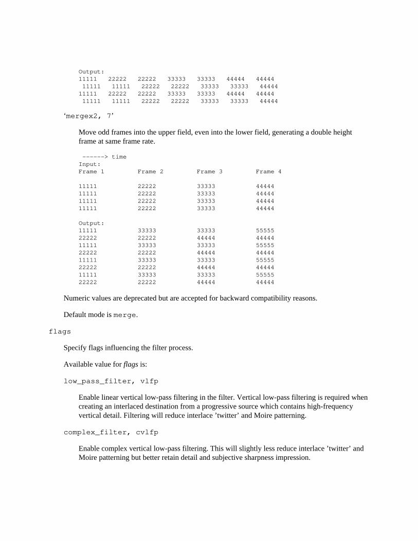
Output:11111 22222 22222 33333 33333 44444 44444 11111 11111 22222 22222 33333 33333 4444411111 22222 22222 33333 33333 44444 44444 11111 11111 22222 22222 33333 33333 44444
‘mergex2, 7’
Move odd frames into the upper field, even into the lower field, generating a double heightframe at same frame rate.
------> timeInput:Frame 1 Frame 2 Frame 3 Frame 4
11111 22222 33333 4444411111 22222 33333 4444411111 22222 33333 4444411111 22222 33333 44444
Output:11111 33333 33333 5555522222 22222 44444 4444411111 33333 33333 5555522222 22222 44444 4444411111 33333 33333 5555522222 22222 44444 4444411111 33333 33333 5555522222 22222 44444 44444
Numeric values are deprecated but are accepted for backward compatibility reasons.
Default mode is merge.
flags
Specify flags influencing the filter process.
Available value for flags is:
low_pass_filter, vlfp
Enable linear vertical low-pass filtering in the filter. Vertical low-pass filtering is required whencreating an interlaced destination from a progressive source which contains high-frequencyvertical detail. Filtering will reduce interlace ’twitter’ and Moire patterning.
complex_filter, cvlfp
Enable complex vertical low-pass filtering. This will slightly less reduce interlace ’twitter’ andMoire patterning but better retain detail and subjective sharpness impression.

Vertical low-pass filtering can only be enabled for mode interleave_top and interleave_bottom.
10.175 tonemap# TOC
Tone map colors from different dynamic ranges.
This filter expects data in single precision floating point, as it needs to operate on (and can output)out-of-range values. Another filter, such as zscale, is needed to convert the resulting frame to a usable format.
The tonemapping algorithms implemented only work on linear light, so input data should be linearizedbeforehand (and possibly correctly tagged).
ffmpeg -i INPUT -vf zscale=transfer=linear,tonemap=clip,zscale=transfer=bt709,format=yuv420p OUTPUT
10.175.1 Options# TOC
The filter accepts the following options.
tonemap
Set the tone map algorithm to use.
Possible values are:
none
Do not apply any tone map, only desaturate overbright pixels.
clip
Hard-clip any out-of-range values. Use it for perfect color accuracy for in-range values, whiledistorting out-of-range values.
linear
Stretch the entire reference gamut to a linear multiple of the display.
gamma
Fit a logarithmic transfer between the tone curves.
reinhard
Preserve overall image brightness with a simple curve, using nonlinear contrast, which results inflattening details and degrading color accuracy.
hable

Preserve both dark and bright details better than reinhard, at the cost of slightly darkeningeverything. Use it when detail preservation is more important than color and brightness accuracy.
mobius
Smoothly map out-of-range values, while retaining contrast and colors for in-range material asmuch as possible. Use it when color accuracy is more important than detail preservation.
Default is none.
param
Tune the tone mapping algorithm.
This affects the following algorithms:
none
Ignored.
linear
Specifies the scale factor to use while stretching. Default to 1.0.
gamma
Specifies the exponent of the function. Default to 1.8.
clip
Specify an extra linear coefficient to multiply into the signal before clipping. Default to 1.0.
reinhard
Specify the local contrast coefficient at the display peak. Default to 0.5, which means thatin-gamut values will be about half as bright as when clipping.
hable
Ignored.
mobius
Specify the transition point from linear to mobius transform. Every value below this point isguaranteed to be mapped 1:1. The higher the value, the more accurate the result will be, at thecost of losing bright details. Default to 0.3, which due to the steep initial slope still preservesin-range colors fairly accurately.
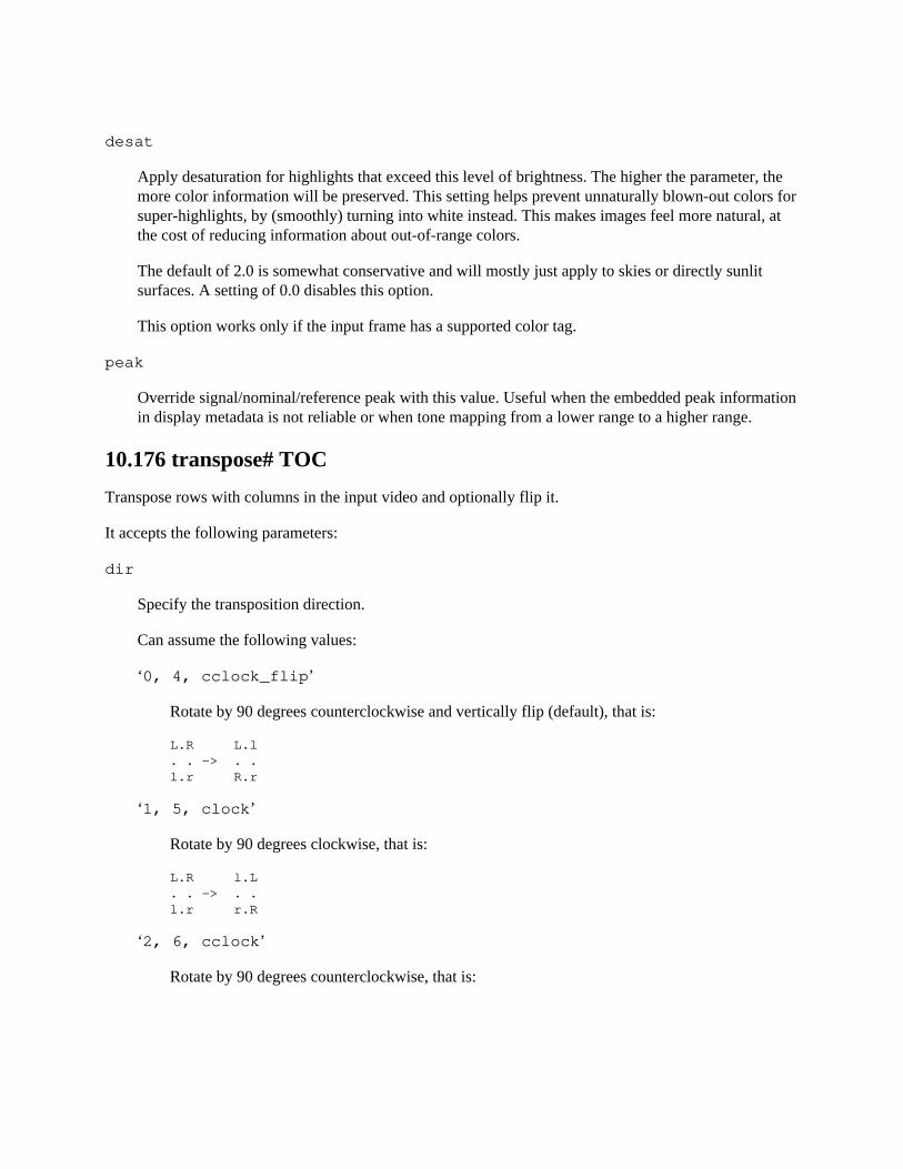
desat
Apply desaturation for highlights that exceed this level of brightness. The higher the parameter, themore color information will be preserved. This setting helps prevent unnaturally blown-out colors forsuper-highlights, by (smoothly) turning into white instead. This makes images feel more natural, atthe cost of reducing information about out-of-range colors.
The default of 2.0 is somewhat conservative and will mostly just apply to skies or directly sunlitsurfaces. A setting of 0.0 disables this option.
This option works only if the input frame has a supported color tag.
peak
Override signal/nominal/reference peak with this value. Useful when the embedded peak informationin display metadata is not reliable or when tone mapping from a lower range to a higher range.
10.176 transpose# TOC
Transpose rows with columns in the input video and optionally flip it.
It accepts the following parameters:
dir
Specify the transposition direction.
Can assume the following values:
‘0, 4, cclock_flip’
Rotate by 90 degrees counterclockwise and vertically flip (default), that is:
L.R L.l. . -> . .l.r R.r
‘1, 5, clock’
Rotate by 90 degrees clockwise, that is:
L.R l.L. . -> . .l.r r.R
‘2, 6, cclock’
Rotate by 90 degrees counterclockwise, that is:
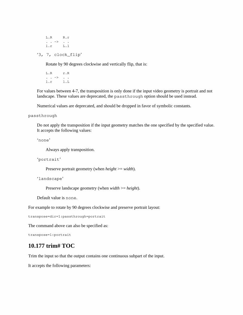
L.R R.r. . -> . .l.r L.l
‘3, 7, clock_flip’
Rotate by 90 degrees clockwise and vertically flip, that is:
L.R r.R. . -> . .l.r l.L
For values between 4-7, the transposition is only done if the input video geometry is portrait and notlandscape. These values are deprecated, the passthrough option should be used instead.
Numerical values are deprecated, and should be dropped in favor of symbolic constants.
passthrough
Do not apply the transposition if the input geometry matches the one specified by the specified value.It accepts the following values:
‘none’
Always apply transposition.
‘portrait’
Preserve portrait geometry (when height >= width).
‘landscape’
Preserve landscape geometry (when width >= height).
Default value is none.
For example to rotate by 90 degrees clockwise and preserve portrait layout:
transpose=dir=1:passthrough=portrait
The command above can also be specified as:
transpose=1:portrait
10.177 trim# TOC
Trim the input so that the output contains one continuous subpart of the input.
It accepts the following parameters:
start
Specify the time of the start of the kept section, i.e. the frame with the timestamp start will be the firstframe in the output.
end
Specify the time of the first frame that will be dropped, i.e. the frame immediately preceding the onewith the timestamp end will be the last frame in the output.
start_pts
This is the same as start, except this option sets the start timestamp in timebase units instead of seconds.
end_pts
This is the same as end, except this option sets the end timestamp in timebase units instead of seconds.
duration
The maximum duration of the output in seconds.
start_frame
The number of the first frame that should be passed to the output.
end_frame
The number of the first frame that should be dropped.
start, end, and duration are expressed as time duration specifications; see (ffmpeg-utils)the Timeduration section in the ffmpeg-utils(1) manual for the accepted syntax.
Note that the first two sets of the start/end options and the duration option look at the frame timestamp,while the _frame variants simply count the frames that pass through the filter. Also note that this filterdoes not modify the timestamps. If you wish for the output timestamps to start at zero, insert a setpts filterafter the trim filter.
If multiple start or end options are set, this filter tries to be greedy and keep all the frames that match atleast one of the specified constraints. To keep only the part that matches all the constraints at once, chainmultiple trim filters.
The defaults are such that all the input is kept. So it is possible to set e.g. just the end values to keepeverything before the specified time.
Examples:
Drop everything except the second minute of input:
ffmpeg -i INPUT -vf trim=60:120
Keep only the first second:
ffmpeg -i INPUT -vf trim=duration=1
10.178 unpremultiply# TOC
Apply alpha unpremultiply effect to input video stream using first plane of second stream as alpha.
Both streams must have same dimensions and same pixel format.
The filter accepts the following option:
planes
Set which planes will be processed, unprocessed planes will be copied. By default value 0xf, allplanes will be processed.
If the format has 1 or 2 components, then luma is bit 0. If the format has 3 or 4 components: for RGBformats bit 0 is green, bit 1 is blue and bit 2 is red; for YUV formats bit 0 is luma, bit 1 is chroma-Uand bit 2 is chroma-V. If present, the alpha channel is always the last bit.
inplace
Do not require 2nd input for processing, instead use alpha plane from input stream.
10.179 unsharp# TOC
Sharpen or blur the input video.
It accepts the following parameters:
luma_msize_x, lx
Set the luma matrix horizontal size. It must be an odd integer between 3 and 23. The default value is 5.
luma_msize_y, ly
Set the luma matrix vertical size. It must be an odd integer between 3 and 23. The default value is 5.
luma_amount, la
Set the luma effect strength. It must be a floating point number, reasonable values lay between -1.5and 1.5.
Negative values will blur the input video, while positive values will sharpen it, a value of zero willdisable the effect.
Default value is 1.0.
chroma_msize_x, cx
Set the chroma matrix horizontal size. It must be an odd integer between 3 and 23. The default valueis 5.
chroma_msize_y, cy
Set the chroma matrix vertical size. It must be an odd integer between 3 and 23. The default value is 5.
chroma_amount, ca
Set the chroma effect strength. It must be a floating point number, reasonable values lay between -1.5and 1.5.
Negative values will blur the input video, while positive values will sharpen it, a value of zero willdisable the effect.
Default value is 0.0.
All parameters are optional and default to the equivalent of the string ’5:5:1.0:5:5:0.0’.
10.179.1 Examples# TOC
Apply strong luma sharpen effect:
unsharp=luma_msize_x=7:luma_msize_y=7:luma_amount=2.5
Apply a strong blur of both luma and chroma parameters:
unsharp=7:7:-2:7:7:-2
10.180 uspp# TOC
Apply ultra slow/simple postprocessing filter that compresses and decompresses the image at several (or -in the case of quality level 8 - all) shifts and average the results.
The way this differs from the behavior of spp is that uspp actually encodes & decodes each case withlibavcodec Snow, whereas spp uses a simplified intra only 8x8 DCT similar to MJPEG.
The filter accepts the following options:
quality
Set quality. This option defines the number of levels for averaging. It accepts an integer in the range0-8. If set to 0, the filter will have no effect. A value of 8 means the higher quality. For eachincrement of that value the speed drops by a factor of approximately 2. Default value is 3.
qp
Force a constant quantization parameter. If not set, the filter will use the QP from the video stream (if available).
10.181 vaguedenoiser# TOC
Apply a wavelet based denoiser.
It transforms each frame from the video input into the wavelet domain, usingCohen-Daubechies-Feauveau 9/7. Then it applies some filtering to the obtained coefficients. It does aninverse wavelet transform after. Due to wavelet properties, it should give a nice smoothed result, andreduced noise, without blurring picture features.
This filter accepts the following options:
threshold
The filtering strength. The higher, the more filtered the video will be. Hard thresholding can use ahigher threshold than soft thresholding before the video looks overfiltered. Default value is 2.
method
The filtering method the filter will use.
It accepts the following values:
‘hard’
All values under the threshold will be zeroed.
‘soft’
All values under the threshold will be zeroed. All values above will be reduced by the threshold.
‘garrote’
Scales or nullifies coefficients - intermediary between (more) soft and (less) hard thresholding.
Default is garrote.
nsteps
Number of times, the wavelet will decompose the picture. Picture can’t be decomposed beyond aparticular point (typically, 8 for a 640x480 frame - as 2^9 = 512 > 480). Valid values are integersbetween 1 and 32. Default value is 6.
percent
Partial of full denoising (limited coefficients shrinking), from 0 to 100. Default value is 85.
planes
A list of the planes to process. By default all planes are processed.
10.182 vectorscope# TOC
Display 2 color component values in the two dimensional graph (which is called a vectorscope).
This filter accepts the following options:
mode, m
Set vectorscope mode.
It accepts the following values:
‘gray’
Gray values are displayed on graph, higher brightness means more pixels have same componentcolor value on location in graph. This is the default mode.
‘color’
Gray values are displayed on graph. Surrounding pixels values which are not present in videoframe are drawn in gradient of 2 color components which are set by option x and y. The 3rdcolor component is static.
‘color2’
Actual color components values present in video frame are displayed on graph.
‘color3’
Similar as color2 but higher frequency of same values x and y on graph increases value ofanother color component, which is luminance by default values of x and y.

‘color4’
Actual colors present in video frame are displayed on graph. If two different colors map to sameposition on graph then color with higher value of component not present in graph is picked.
‘color5’
Gray values are displayed on graph. Similar to color but with 3rd color component pickedfrom radial gradient.
x
Set which color component will be represented on X-axis. Default is 1.
y
Set which color component will be represented on Y-axis. Default is 2.
intensity, i
Set intensity, used by modes: gray, color, color3 and color5 for increasing brightness of colorcomponent which represents frequency of (X, Y) location in graph.
envelope, e ‘none’
No envelope, this is default.
‘instant’
Instant envelope, even darkest single pixel will be clearly highlighted.
‘peak’
Hold maximum and minimum values presented in graph over time. This way you can still spotout of range values without constantly looking at vectorscope.
‘peak+instant’
Peak and instant envelope combined together.
graticule, g
Set what kind of graticule to draw.
‘none’ ‘green’ ‘color’
opacity, o
Set graticule opacity.
flags, f
Set graticule flags.
‘white’
Draw graticule for white point.
‘black’
Draw graticule for black point.
‘name’
Draw color points short names.
bgopacity, b
Set background opacity.
lthreshold, l
Set low threshold for color component not represented on X or Y axis. Values lower than this valuewill be ignored. Default is 0. Note this value is multiplied with actual max possible value one pixelcomponent can have. So for 8-bit input and low threshold value of 0.1 actual threshold is 0.1 * 255 = 25.
hthreshold, h
Set high threshold for color component not represented on X or Y axis. Values higher than this valuewill be ignored. Default is 1. Note this value is multiplied with actual max possible value one pixelcomponent can have. So for 8-bit input and high threshold value of 0.9 actual threshold is 0.9 * 255 = 230.
colorspace, c
Set what kind of colorspace to use when drawing graticule.
‘auto’ ‘601’ ‘709’
Default is auto.

10.183 vidstabdetect# TOC
Analyze video stabilization/deshaking. Perform pass 1 of 2, see vidstabtransform for pass 2.
This filter generates a file with relative translation and rotation transform information about subsequentframes, which is then used by the vidstabtransform filter.
To enable compilation of this filter you need to configure FFmpeg with --enable-libvidstab.
This filter accepts the following options:
result
Set the path to the file used to write the transforms information. Default value is transforms.trf.
shakiness
Set how shaky the video is and how quick the camera is. It accepts an integer in the range 1-10, avalue of 1 means little shakiness, a value of 10 means strong shakiness. Default value is 5.
accuracy
Set the accuracy of the detection process. It must be a value in the range 1-15. A value of 1 meanslow accuracy, a value of 15 means high accuracy. Default value is 15.
stepsize
Set stepsize of the search process. The region around minimum is scanned with 1 pixel resolution.Default value is 6.
mincontrast
Set minimum contrast. Below this value a local measurement field is discarded. Must be a floatingpoint value in the range 0-1. Default value is 0.3.
tripod
Set reference frame number for tripod mode.
If enabled, the motion of the frames is compared to a reference frame in the filtered stream, identifiedby the specified number. The idea is to compensate all movements in a more-or-less static scene andkeep the camera view absolutely still.
If set to 0, it is disabled. The frames are counted starting from 1.
show
Show fields and transforms in the resulting frames. It accepts an integer in the range 0-2. Defaultvalue is 0, which disables any visualization.
10.183.1 Examples# TOC
Use default values:
vidstabdetect
Analyze strongly shaky movie and put the results in file mytransforms.trf:
vidstabdetect=shakiness=10:accuracy=15:result="mytransforms.trf"
Visualize the result of internal transformations in the resulting video:
vidstabdetect=show=1
Analyze a video with medium shakiness using ffmpeg:
ffmpeg -i input -vf vidstabdetect=shakiness=5:show=1 dummy.avi
10.184 vidstabtransform# TOC
Video stabilization/deshaking: pass 2 of 2, see vidstabdetect for pass 1.
Read a file with transform information for each frame and apply/compensate them. Together with the vidstabdetect filter this can be used to deshake videos. See also http://public.hronopik.de/vid.stab. It isimportant to also use the unsharp filter, see below.
To enable compilation of this filter you need to configure FFmpeg with --enable-libvidstab.
10.184.1 Options# TOC
input
Set path to the file used to read the transforms. Default value is transforms.trf.
smoothing
Set the number of frames (value*2 + 1) used for lowpass filtering the camera movements. Defaultvalue is 10.
For example a number of 10 means that 21 frames are used (10 in the past and 10 in the future) tosmoothen the motion in the video. A larger value leads to a smoother video, but limits theacceleration of the camera (pan/tilt movements). 0 is a special case where a static camera is simulated.
optalgo
Set the camera path optimization algorithm.
Accepted values are:
‘gauss’
gaussian kernel low-pass filter on camera motion (default)
‘avg’
averaging on transformations
maxshift
Set maximal number of pixels to translate frames. Default value is -1, meaning no limit.
maxangle
Set maximal angle in radians (degree*PI/180) to rotate frames. Default value is -1, meaning no limit.
crop
Specify how to deal with borders that may be visible due to movement compensation.
Available values are:
‘keep’
keep image information from previous frame (default)
‘black’
fill the border black
invert
Invert transforms if set to 1. Default value is 0.
relative
Consider transforms as relative to previous frame if set to 1, absolute if set to 0. Default value is 0.
zoom
Set percentage to zoom. A positive value will result in a zoom-in effect, a negative value in azoom-out effect. Default value is 0 (no zoom).
optzoom
Set optimal zooming to avoid borders.
Accepted values are:
‘0’
disabled
‘1’
optimal static zoom value is determined (only very strong movements will lead to visibleborders) (default)
‘2’
optimal adaptive zoom value is determined (no borders will be visible), see zoomspeed
Note that the value given at zoom is added to the one calculated here.
zoomspeed
Set percent to zoom maximally each frame (enabled when optzoom is set to 2). Range is from 0 to5, default value is 0.25.
interpol
Specify type of interpolation.
Available values are:
‘no’
no interpolation
‘linear’
linear only horizontal
‘bilinear’
linear in both directions (default)
‘bicubic’
cubic in both directions (slow)
tripod
Enable virtual tripod mode if set to 1, which is equivalent to relative=0:smoothing=0.Default value is 0.
Use also tripod option of vidstabdetect.
debug
Increase log verbosity if set to 1. Also the detected global motions are written to the temporary file global_motions.trf. Default value is 0.
10.184.2 Examples# TOC
Use ffmpeg for a typical stabilization with default values:
ffmpeg -i inp.mpeg -vf vidstabtransform,unsharp=5:5:0.8:3:3:0.4 inp_stabilized.mpeg
Note the use of the unsharp filter which is always recommended.
Zoom in a bit more and load transform data from a given file:
vidstabtransform=zoom=5:input="mytransforms.trf"
Smoothen the video even more:
vidstabtransform=smoothing=30
10.185 vflip# TOC
Flip the input video vertically.
For example, to vertically flip a video with ffmpeg:
ffmpeg -i in.avi -vf "vflip" out.avi
10.186 vfrdet# TOC
Detect variable frame rate video.
This filter tries to detect if the input is variable or constant frame rate.
At end it will output number of frames detected as having variable delta pts, and ones with constant deltapts. If there was frames with variable delta, than it will also show min and max delta encountered.
10.187 vignette# TOC
Make or reverse a natural vignetting effect.
The filter accepts the following options:
angle, a
Set lens angle expression as a number of radians.
The value is clipped in the [0,PI/2] range.
Default value: "PI/5"
x0 y0
Set center coordinates expressions. Respectively "w/2" and "h/2" by default.
mode
Set forward/backward mode.
Available modes are:
‘forward’
The larger the distance from the central point, the darker the image becomes.
‘backward’
The larger the distance from the central point, the brighter the image becomes. This can be usedto reverse a vignette effect, though there is no automatic detection to extract the lens angle andother settings (yet). It can also be used to create a burning effect.
Default value is ‘forward’.
eval
Set evaluation mode for the expressions (angle, x0, y0).
It accepts the following values:
‘init’
Evaluate expressions only once during the filter initialization.
‘frame’
Evaluate expressions for each incoming frame. This is way slower than the ‘init’ mode sinceit requires all the scalers to be re-computed, but it allows advanced dynamic expressions.
Default value is ‘init’.
dither
Set dithering to reduce the circular banding effects. Default is 1 (enabled).
aspect
Set vignette aspect. This setting allows one to adjust the shape of the vignette. Setting this value tothe SAR of the input will make a rectangular vignetting following the dimensions of the video.
Default is 1/1.
10.187.1 Expressions# TOC
The alpha, x0 and y0 expressions can contain the following parameters.
w h
input width and height
n
the number of input frame, starting from 0
pts
the PTS (Presentation TimeStamp) time of the filtered video frame, expressed in TB units, NAN if undefined
r
frame rate of the input video, NAN if the input frame rate is unknown
t
the PTS (Presentation TimeStamp) of the filtered video frame, expressed in seconds, NAN if undefined
tb
time base of the input video
10.187.2 Examples# TOC
Apply simple strong vignetting effect:
vignette=PI/4
Make a flickering vignetting:
vignette=’PI/4+random(1)*PI/50’:eval=frame
10.188 vmafmotion# TOC
Obtain the average vmaf motion score of a video. It is one of the component filters of VMAF.
The obtained average motion score is printed through the logging system.
In the below example the input file ref.mpg is being processed and score is computed.
ffmpeg -i ref.mpg -lavfi vmafmotion -f null -
10.189 vstack# TOC
Stack input videos vertically.
All streams must be of same pixel format and of same width.
Note that this filter is faster than using overlay and pad filter to create same output.
The filter accept the following option:
inputs
Set number of input streams. Default is 2.
shortest
If set to 1, force the output to terminate when the shortest input terminates. Default value is 0.
10.190 w3fdif# TOC
Deinterlace the input video ("w3fdif" stands for "Weston 3 Field Deinterlacing Filter").
Based on the process described by Martin Weston for BBC R&D, and implemented based on thede-interlace algorithm written by Jim Easterbrook for BBC R&D, the Weston 3 field deinterlacing filteruses filter coefficients calculated by BBC R&D.
There are two sets of filter coefficients, so called "simple": and "complex". Which set of filter coefficientsis used can be set by passing an optional parameter:
filter
Set the interlacing filter coefficients. Accepts one of the following values:
‘simple’
Simple filter coefficient set.
‘complex’
More-complex filter coefficient set.
Default value is ‘complex’.
deint
Specify which frames to deinterlace. Accept one of the following values:
‘all’
Deinterlace all frames,
‘interlaced’
Only deinterlace frames marked as interlaced.
Default value is ‘all’.
10.191 waveform# TOC
Video waveform monitor.
The waveform monitor plots color component intensity. By default luminance only. Each column of thewaveform corresponds to a column of pixels in the source video.
It accepts the following options:
mode, m
Can be either row, or column. Default is column. In row mode, the graph on the left siderepresents color component value 0 and the right side represents value = 255. In column mode, thetop side represents color component value = 0 and bottom side represents value = 255.
intensity, i
Set intensity. Smaller values are useful to find out how many values of the same luminance aredistributed across input rows/columns. Default value is 0.04. Allowed range is [0, 1].
mirror, r
Set mirroring mode. 0 means unmirrored, 1 means mirrored. In mirrored mode, higher values will berepresented on the left side for row mode and at the top for column mode. Default is 1 (mirrored).
display, d
Set display mode. It accepts the following values:
‘overlay’
Presents information identical to that in the parade, except that the graphs representing colorcomponents are superimposed directly over one another.
This display mode makes it easier to spot relative differences or similarities in overlapping areasof the color components that are supposed to be identical, such as neutral whites, grays, or blacks.
‘stack’
Display separate graph for the color components side by side in row mode or one below theother in column mode.
‘parade’
Display separate graph for the color components side by side in column mode or one below theother in row mode.
Using this display mode makes it easy to spot color casts in the highlights and shadows of animage, by comparing the contours of the top and the bottom graphs of each waveform. Sincewhites, grays, and blacks are characterized by exactly equal amounts of red, green, and blue,neutral areas of the picture should display three waveforms of roughly equal width/height. If not,the correction is easy to perform by making level adjustments the three waveforms.
Default is stack.
components, c
Set which color components to display. Default is 1, which means only luminance or red colorcomponent if input is in RGB colorspace. If is set for example to 7 it will display all 3 (if) availablecolor components.
envelope, e ‘none’
No envelope, this is default.
‘instant’
Instant envelope, minimum and maximum values presented in graph will be easily visible evenwith small step value.
‘peak’
Hold minimum and maximum values presented in graph across time. This way you can still spotout of range values without constantly looking at waveforms.
‘peak+instant’
Peak and instant envelope combined together.
filter, f ‘lowpass’
No filtering, this is default.
‘flat’
Luma and chroma combined together.
‘aflat’
Similar as above, but shows difference between blue and red chroma.
‘xflat’
Similar as above, but use different colors.
‘chroma’
Displays only chroma.
‘color’
Displays actual color value on waveform.
‘acolor’
Similar as above, but with luma showing frequency of chroma values.
graticule, g
Set which graticule to display.
‘none’
Do not display graticule.

‘green’
Display green graticule showing legal broadcast ranges.
‘orange’
Display orange graticule showing legal broadcast ranges.
opacity, o
Set graticule opacity.
flags, fl
Set graticule flags.
‘numbers’
Draw numbers above lines. By default enabled.
‘dots’
Draw dots instead of lines.
scale, s
Set scale used for displaying graticule.
‘digital’ ‘millivolts’ ‘ire’
Default is digital.
bgopacity, b
Set background opacity.
10.192 weave, doubleweave# TOC
The weave takes a field-based video input and join each two sequential fields into single frame,producing a new double height clip with half the frame rate and half the frame count.
The doubleweave works same as weave but without halving frame rate and frame count.
It accepts the following option:
first_field
Set first field. Available values are:
‘top, t’
Set the frame as top-field-first.
‘bottom, b’
Set the frame as bottom-field-first.
10.192.1 Examples# TOC
Interlace video using select and separatefields filter:
separatefields,select=eq(mod(n,4),0)+eq(mod(n,4),3),weave
10.193 xbr# TOC
Apply the xBR high-quality magnification filter which is designed for pixel art. It follows a set ofedge-detection rules, see http://www.libretro.com/forums/viewtopic.php?f=6&t=134.
It accepts the following option:
n
Set the scaling dimension: 2 for 2xBR, 3 for 3xBR and 4 for 4xBR. Default is 3.
10.194 yadif# TOC
Deinterlace the input video ("yadif" means "yet another deinterlacing filter").
It accepts the following parameters:
mode
The interlacing mode to adopt. It accepts one of the following values:
0, send_frame
Output one frame for each frame.
1, send_field
Output one frame for each field.
2, send_frame_nospatial
Like send_frame, but it skips the spatial interlacing check.
3, send_field_nospatial
Like send_field, but it skips the spatial interlacing check.
The default value is send_frame.
parity
The picture field parity assumed for the input interlaced video. It accepts one of the following values:
0, tff
Assume the top field is first.
1, bff
Assume the bottom field is first.
-1, auto
Enable automatic detection of field parity.
The default value is auto. If the interlacing is unknown or the decoder does not export thisinformation, top field first will be assumed.
deint
Specify which frames to deinterlace. Accept one of the following values:
0, all
Deinterlace all frames.
1, interlaced
Only deinterlace frames marked as interlaced.
The default value is all.
10.195 zoompan# TOC
Apply Zoom & Pan effect.
This filter accepts the following options:
zoom, z
Set the zoom expression. Default is 1.
x y
Set the x and y expression. Default is 0.
d
Set the duration expression in number of frames. This sets for how many number of frames effectwill last for single input image.
s
Set the output image size, default is ’hd720’.
fps
Set the output frame rate, default is ’25’.
Each expression can contain the following constants:
in_w, iw
Input width.
in_h, ih
Input height.
out_w, ow
Output width.
out_h, oh
Output height.
in
Input frame count.
on
Output frame count.
x y
Last calculated ’x’ and ’y’ position from ’x’ and ’y’ expression for current input frame.
px py
’x’ and ’y’ of last output frame of previous input frame or 0 when there was not yet such frame (firstinput frame).
zoom
Last calculated zoom from ’z’ expression for current input frame.
pzoom
Last calculated zoom of last output frame of previous input frame.
duration
Number of output frames for current input frame. Calculated from ’d’ expression for each input frame.
pduration
number of output frames created for previous input frame
a
Rational number: input width / input height
sar
sample aspect ratio
dar
display aspect ratio
10.195.1 Examples# TOC
Zoom-in up to 1.5 and pan at same time to some spot near center of picture:
zoompan=z=’min(zoom+0.0015,1.5)’:d=700:x=’if(gte(zoom,1.5),x,x+1/a)’:y=’if(gte(zoom,1.5),y,y+1)’:s=640x360
Zoom-in up to 1.5 and pan always at center of picture:
zoompan=z=’min(zoom+0.0015,1.5)’:d=700:x=’iw/2-(iw/zoom/2)’:y=’ih/2-(ih/zoom/2)’
Same as above but without pausing:
zoompan=z=’min(max(zoom,pzoom)+0.0015,1.5)’:d=1:x=’iw/2-(iw/zoom/2)’:y=’ih/2-(ih/zoom/2)’
10.196 zscale# TOC
Scale (resize) the input video, using the z.lib library: https://github.com/sekrit-twc/zimg.
The zscale filter forces the output display aspect ratio to be the same as the input, by changing the outputsample aspect ratio.
If the input image format is different from the format requested by the next filter, the zscale filter willconvert the input to the requested format.
10.196.1 Options# TOC
The filter accepts the following options.
width, w height, h
Set the output video dimension expression. Default value is the input dimension.
If the width or w value is 0, the input width is used for the output. If the height or h value is 0, theinput height is used for the output.
If one and only one of the values is -n with n >= 1, the zscale filter will use a value that maintains theaspect ratio of the input image, calculated from the other specified dimension. After that it will,however, make sure that the calculated dimension is divisible by n and adjust the value if necessary.
If both values are -n with n >= 1, the behavior will be identical to both values being set to 0 aspreviously detailed.
See below for the list of accepted constants for use in the dimension expression.
size, s
Set the video size. For the syntax of this option, check the (ffmpeg-utils)"Video size" section in theffmpeg-utils manual.
dither, d
Set the dither type.
Possible values are:
none ordered random
error_diffusion
Default is none.
filter, f
Set the resize filter type.
Possible values are:
point bilinear bicubic spline16 spline36 lanczos
Default is bilinear.
range, r
Set the color range.
Possible values are:
input limited full
Default is same as input.
primaries, p
Set the color primaries.
Possible values are:
input 709 unspecified 170m 240m 2020
Default is same as input.
transfer, t
Set the transfer characteristics.
Possible values are:
input 709 unspecified 601 linear 2020_10 2020_12 smpte2084 iec61966-2-1 arib-std-b67
Default is same as input.
matrix, m
Set the colorspace matrix.
Possible value are:
input 709 unspecified 470bg 170m 2020_ncl 2020_cl
Default is same as input.
rangein, rin
Set the input color range.
Possible values are:
input limited full
Default is same as input.
primariesin, pin
Set the input color primaries.
Possible values are:
input 709 unspecified 170m 240m 2020
Default is same as input.
transferin, tin
Set the input transfer characteristics.
Possible values are:
input 709 unspecified 601 linear 2020_10 2020_12
Default is same as input.
matrixin, min
Set the input colorspace matrix.
Possible value are:
input 709 unspecified 470bg 170m 2020_ncl 2020_cl
chromal, c
Set the output chroma location.
Possible values are:
input left center topleft top bottomleft bottom
chromalin, cin
Set the input chroma location.
Possible values are:
input left center topleft top bottomleft bottom
npl
Set the nominal peak luminance.
The values of the w and h options are expressions containing the following constants:
in_w in_h
The input width and height
iw ih
These are the same as in_w and in_h.
out_w out_h
The output (scaled) width and height
ow oh
These are the same as out_w and out_h
a

The same as iw / ih
sar
input sample aspect ratio
dar
The input display aspect ratio. Calculated from (iw / ih) * sar.
hsub vsub
horizontal and vertical input chroma subsample values. For example for the pixel format "yuv422p" hsub is 2 and vsub is 1.
ohsub ovsub
horizontal and vertical output chroma subsample values. For example for the pixel format "yuv422p" hsub is 2 and vsub is 1.
11 Video Sources# TOCBelow is a description of the currently available video sources.
11.1 buffer# TOC
Buffer video frames, and make them available to the filter chain.
This source is mainly intended for a programmatic use, in particular through the interface defined in libavfilter/vsrc_buffer.h.
It accepts the following parameters:
video_size
Specify the size (width and height) of the buffered video frames. For the syntax of this option, checkthe (ffmpeg-utils)"Video size" section in the ffmpeg-utils manual.
width
The input video width.
height
The input video height.
pix_fmt
A string representing the pixel format of the buffered video frames. It may be a numbercorresponding to a pixel format, or a pixel format name.
time_base
Specify the timebase assumed by the timestamps of the buffered frames.
frame_rate
Specify the frame rate expected for the video stream.
pixel_aspect, sar
The sample (pixel) aspect ratio of the input video.
sws_param
Specify the optional parameters to be used for the scale filter which is automatically inserted when aninput change is detected in the input size or format.
hw_frames_ctx
When using a hardware pixel format, this should be a reference to an AVHWFramesContextdescribing input frames.
For example:
buffer=width=320:height=240:pix_fmt=yuv410p:time_base=1/24:sar=1
will instruct the source to accept video frames with size 320x240 and with format "yuv410p", assuming1/24 as the timestamps timebase and square pixels (1:1 sample aspect ratio). Since the pixel format withname "yuv410p" corresponds to the number 6 (check the enum AVPixelFormat definition in libavutil/pixfmt.h), this example corresponds to:
buffer=size=320x240:pixfmt=6:time_base=1/24:pixel_aspect=1/1
Alternatively, the options can be specified as a flat string, but this syntax is deprecated:
width:height:pix_fmt:time_base.num:time_base.den:pixel_aspect.num:pixel_aspect.den[:sws_param]
11.2 cellauto# TOC
Create a pattern generated by an elementary cellular automaton.
The initial state of the cellular automaton can be defined through the filename and pattern options.If such options are not specified an initial state is created randomly.
At each new frame a new row in the video is filled with the result of the cellular automaton nextgeneration. The behavior when the whole frame is filled is defined by the scroll option.
This source accepts the following options:
filename, f
Read the initial cellular automaton state, i.e. the starting row, from the specified file. In the file, eachnon-whitespace character is considered an alive cell, a newline will terminate the row, and furthercharacters in the file will be ignored.
pattern, p
Read the initial cellular automaton state, i.e. the starting row, from the specified string.
Each non-whitespace character in the string is considered an alive cell, a newline will terminate therow, and further characters in the string will be ignored.
rate, r
Set the video rate, that is the number of frames generated per second. Default is 25.
random_fill_ratio, ratio
Set the random fill ratio for the initial cellular automaton row. It is a floating point number valueranging from 0 to 1, defaults to 1/PHI.
This option is ignored when a file or a pattern is specified.
random_seed, seed
Set the seed for filling randomly the initial row, must be an integer included between 0 andUINT32_MAX. If not specified, or if explicitly set to -1, the filter will try to use a good random seedon a best effort basis.
rule
Set the cellular automaton rule, it is a number ranging from 0 to 255. Default value is 110.
size, s
Set the size of the output video. For the syntax of this option, check the (ffmpeg-utils)"Video size"section in the ffmpeg-utils manual.
If filename or pattern is specified, the size is set by default to the width of the specified initialstate row, and the height is set to width * PHI.
If size is set, it must contain the width of the specified pattern string, and the specified pattern willbe centered in the larger row.
If a filename or a pattern string is not specified, the size value defaults to "320x518" (used for arandomly generated initial state).
scroll
If set to 1, scroll the output upward when all the rows in the output have been already filled. If set to0, the new generated row will be written over the top row just after the bottom row is filled. Defaultsto 1.
start_full, full
If set to 1, completely fill the output with generated rows before outputting the first frame. This is thedefault behavior, for disabling set the value to 0.
stitch
If set to 1, stitch the left and right row edges together. This is the default behavior, for disabling setthe value to 0.
11.2.1 Examples# TOC
Read the initial state from pattern, and specify an output of size 200x400.
cellauto=f=pattern:s=200x400
Generate a random initial row with a width of 200 cells, with a fill ratio of 2/3:
cellauto=ratio=2/3:s=200x200
Create a pattern generated by rule 18 starting by a single alive cell centered on an initial row withwidth 100:
cellauto=p=@:s=100x400:full=0:rule=18
Specify a more elaborated initial pattern:
cellauto=p=’@@ @ @@’:s=100x400:full=0:rule=18
11.3 coreimagesrc# TOC
Video source generated on GPU using Apple’s CoreImage API on OSX.
This video source is a specialized version of the coreimage video filter. Use a core image generator at thebeginning of the applied filterchain to generate the content.
The coreimagesrc video source accepts the following options:
list_generators
List all available generators along with all their respective options as well as possible minimum andmaximum values along with the default values.
list_generators=true
size, s
Specify the size of the sourced video. For the syntax of this option, check the (ffmpeg-utils)"Videosize" section in the ffmpeg-utils manual. The default value is 320x240.
rate, r
Specify the frame rate of the sourced video, as the number of frames generated per second. It has tobe a string in the format frame_rate_num/frame_rate_den, an integer number, a floating pointnumber or a valid video frame rate abbreviation. The default value is "25".
sar
Set the sample aspect ratio of the sourced video.
duration, d
Set the duration of the sourced video. See (ffmpeg-utils)the Time duration section in theffmpeg-utils(1) manual for the accepted syntax.
If not specified, or the expressed duration is negative, the video is supposed to be generated forever.
Additionally, all options of the coreimage video filter are accepted. A complete filterchain can be used forfurther processing of the generated input without CPU-HOST transfer. See coreimage documentation andexamples for details.
11.3.1 Examples# TOC
Use CIQRCodeGenerator to create a QR code for the FFmpeg homepage, given as complete andescaped command-line for Apple’s standard bash shell:
ffmpeg -f lavfi -i coreimagesrc=s=100x100:filter=CIQRCodeGenerator@inputMessage=https\\\\\://FFmpeg.org/@inputCorrectionLevel=H -frames:v 1 QRCode.png
This example is equivalent to the QRCode example of coreimage without the need for a nullsrc video source.
11.4 mandelbrot# TOC
Generate a Mandelbrot set fractal, and progressively zoom towards the point specified with start_x and start_y.
This source accepts the following options:
end_pts
Set the terminal pts value. Default value is 400.
end_scale
Set the terminal scale value. Must be a floating point value. Default value is 0.3.
inner
Set the inner coloring mode, that is the algorithm used to draw the Mandelbrot fractal internal region.
It shall assume one of the following values:
black
Set black mode.
convergence
Show time until convergence.
mincol
Set color based on point closest to the origin of the iterations.
period
Set period mode.
Default value is mincol.
bailout
Set the bailout value. Default value is 10.0.
maxiter
Set the maximum of iterations performed by the rendering algorithm. Default value is 7189.
outer
Set outer coloring mode. It shall assume one of following values:
iteration_count
Set iteration cound mode.
normalized_iteration_count
set normalized iteration count mode.
Default value is normalized_iteration_count.
rate, r
Set frame rate, expressed as number of frames per second. Default value is "25".
size, s
Set frame size. For the syntax of this option, check the (ffmpeg-utils)"Video size" section in theffmpeg-utils manual. Default value is "640x480".
start_scale
Set the initial scale value. Default value is 3.0.
start_x
Set the initial x position. Must be a floating point value between -100 and 100. Default value is -0.743643887037158704752191506114774.
start_y
Set the initial y position. Must be a floating point value between -100 and 100. Default value is -0.131825904205311970493132056385139.
11.5 mptestsrc# TOC
Generate various test patterns, as generated by the MPlayer test filter.
The size of the generated video is fixed, and is 256x256. This source is useful in particular for testingencoding features.
This source accepts the following options:
rate, r
Specify the frame rate of the sourced video, as the number of frames generated per second. It has tobe a string in the format frame_rate_num/frame_rate_den, an integer number, a floating pointnumber or a valid video frame rate abbreviation. The default value is "25".
duration, d
Set the duration of the sourced video. See (ffmpeg-utils)the Time duration section in theffmpeg-utils(1) manual for the accepted syntax.
If not specified, or the expressed duration is negative, the video is supposed to be generated forever.
test, t
Set the number or the name of the test to perform. Supported tests are:
dc_luma dc_chroma freq_luma freq_chroma amp_luma amp_chroma cbp mv ring1 ring2 all
Default value is "all", which will cycle through the list of all tests.
Some examples:
mptestsrc=t=dc_luma
will generate a "dc_luma" test pattern.
11.6 frei0r_src# TOC
Provide a frei0r source.
To enable compilation of this filter you need to install the frei0r header and configure FFmpeg with --enable-frei0r.
This source accepts the following parameters:
size
The size of the video to generate. For the syntax of this option, check the (ffmpeg-utils)"Video size"section in the ffmpeg-utils manual.
framerate
The framerate of the generated video. It may be a string of the form num/den or a frame rate abbreviation.
filter_name
The name to the frei0r source to load. For more information regarding frei0r and how to set theparameters, read the frei0r section in the video filters documentation.
filter_params
A ’|’-separated list of parameters to pass to the frei0r source.
For example, to generate a frei0r partik0l source with size 200x200 and frame rate 10 which is overlaid onthe overlay filter main input:
frei0r_src=size=200x200:framerate=10:filter_name=partik0l:filter_params=1234 [overlay]; [in][overlay] overlay
11.7 life# TOC
Generate a life pattern.
This source is based on a generalization of John Conway’s life game.
The sourced input represents a life grid, each pixel represents a cell which can be in one of two possiblestates, alive or dead. Every cell interacts with its eight neighbours, which are the cells that are horizontally,vertically, or diagonally adjacent.
At each interaction the grid evolves according to the adopted rule, which specifies the number of neighboralive cells which will make a cell stay alive or born. The rule option allows one to specify the rule to adopt.
This source accepts the following options:
filename, f
Set the file from which to read the initial grid state. In the file, each non-whitespace character isconsidered an alive cell, and newline is used to delimit the end of each row.
If this option is not specified, the initial grid is generated randomly.
rate, r
Set the video rate, that is the number of frames generated per second. Default is 25.
random_fill_ratio, ratio
Set the random fill ratio for the initial random grid. It is a floating point number value ranging from 0to 1, defaults to 1/PHI. It is ignored when a file is specified.
random_seed, seed
Set the seed for filling the initial random grid, must be an integer included between 0 andUINT32_MAX. If not specified, or if explicitly set to -1, the filter will try to use a good random seedon a best effort basis.
rule
Set the life rule.
A rule can be specified with a code of the kind "SNS/BNB", where NS and NB are sequences ofnumbers in the range 0-8, NS specifies the number of alive neighbor cells which make a live cell stayalive, and NB the number of alive neighbor cells which make a dead cell to become alive (i.e. to"born"). "s" and "b" can be used in place of "S" and "B", respectively.
Alternatively a rule can be specified by an 18-bits integer. The 9 high order bits are used to encodethe next cell state if it is alive for each number of neighbor alive cells, the low order bits specify therule for "borning" new cells. Higher order bits encode for an higher number of neighbor cells. Forexample the number 6153 = (12<<9)+9 specifies a stay alive rule of 12 and a born rule of 9, whichcorresponds to "S23/B03".
Default value is "S23/B3", which is the original Conway’s game of life rule, and will keep a cell aliveif it has 2 or 3 neighbor alive cells, and will born a new cell if there are three alive cells around a dead cell.
size, s
Set the size of the output video. For the syntax of this option, check the (ffmpeg-utils)"Video size"section in the ffmpeg-utils manual.
If filename is specified, the size is set by default to the same size of the input file. If size is set, itmust contain the size specified in the input file, and the initial grid defined in that file is centered inthe larger resulting area.
If a filename is not specified, the size value defaults to "320x240" (used for a randomly generatedinitial grid).
stitch
If set to 1, stitch the left and right grid edges together, and the top and bottom edges also. Defaults to 1.
mold
Set cell mold speed. If set, a dead cell will go from death_color to mold_color with a step of mold. mold can have a value from 0 to 255.

life_color
Set the color of living (or new born) cells.
death_color
Set the color of dead cells. If mold is set, this is the first color used to represent a dead cell.
mold_color
Set mold color, for definitely dead and moldy cells.
For the syntax of these 3 color options, check the (ffmpeg-utils)"Color" section in the ffmpeg-utils manual.
11.7.1 Examples# TOC
Read a grid from pattern, and center it on a grid of size 300x300 pixels:
life=f=pattern:s=300x300
Generate a random grid of size 200x200, with a fill ratio of 2/3:
life=ratio=2/3:s=200x200
Specify a custom rule for evolving a randomly generated grid:
life=rule=S14/B34
Full example with slow death effect (mold) using ffplay:
ffplay -f lavfi life=s=300x200:mold=10:r=60:ratio=0.1:death_color=#C83232:life_color=#00ff00,scale=1200:800:flags=16
11.8 allrgb, allyuv, color, haldclutsrc, nullsrc, rgbtestsrc, smptebars,smptehdbars, testsrc, testsrc2, yuvtestsrc# TOC
The allrgb source returns frames of size 4096x4096 of all rgb colors.
The allyuv source returns frames of size 4096x4096 of all yuv colors.
The color source provides an uniformly colored input.
The haldclutsrc source provides an identity Hald CLUT. See also haldclut filter.
The nullsrc source returns unprocessed video frames. It is mainly useful to be employed in analysis /debugging tools, or as the source for filters which ignore the input data.
The rgbtestsrc source generates an RGB test pattern useful for detecting RGB vs BGR issues. Youshould see a red, green and blue stripe from top to bottom.
The smptebars source generates a color bars pattern, based on the SMPTE Engineering Guideline EG 1-1990.
The smptehdbars source generates a color bars pattern, based on the SMPTE RP 219-2002.
The testsrc source generates a test video pattern, showing a color pattern, a scrolling gradient and atimestamp. This is mainly intended for testing purposes.
The testsrc2 source is similar to testsrc, but supports more pixel formats instead of just rgb24. Thisallows using it as an input for other tests without requiring a format conversion.
The yuvtestsrc source generates an YUV test pattern. You should see a y, cb and cr stripe from top to bottom.
The sources accept the following parameters:
level
Specify the level of the Hald CLUT, only available in the haldclutsrc source. A level of Ngenerates a picture of N*N*N by N*N*N pixels to be used as identity matrix for 3D lookup tables.Each component is coded on a 1/(N*N) scale.
color, c
Specify the color of the source, only available in the color source. For the syntax of this option,check the (ffmpeg-utils)"Color" section in the ffmpeg-utils manual.
size, s
Specify the size of the sourced video. For the syntax of this option, check the (ffmpeg-utils)"Videosize" section in the ffmpeg-utils manual. The default value is 320x240.
This option is not available with the allrgb, allyuv, and haldclutsrc filters.
rate, r
Specify the frame rate of the sourced video, as the number of frames generated per second. It has tobe a string in the format frame_rate_num/frame_rate_den, an integer number, a floating pointnumber or a valid video frame rate abbreviation. The default value is "25".
duration, d
Set the duration of the sourced video. See (ffmpeg-utils)the Time duration section in theffmpeg-utils(1) manual for the accepted syntax.
If not specified, or the expressed duration is negative, the video is supposed to be generated forever.
sar
Set the sample aspect ratio of the sourced video.
alpha
Specify the alpha (opacity) of the background, only available in the testsrc2 source. The valuemust be between 0 (fully transparent) and 255 (fully opaque, the default).
decimals, n
Set the number of decimals to show in the timestamp, only available in the testsrc source.
The displayed timestamp value will correspond to the original timestamp value multiplied by thepower of 10 of the specified value. Default value is 0.
11.8.1 Examples# TOC
Generate a video with a duration of 5.3 seconds, with size 176x144 and a frame rate of 10 frames persecond:
testsrc=duration=5.3:size=qcif:rate=10
The following graph description will generate a red source with an opacity of 0.2, with size "qcif"and a frame rate of 10 frames per second:
[email protected]:s=qcif:r=10
If the input content is to be ignored, nullsrc can be used. The following command generates noisein the luminance plane by employing the geq filter:
nullsrc=s=256x256, geq=random(1)*255:128:128
11.8.2 Commands# TOC
The color source supports the following commands:
c, color
Set the color of the created image. Accepts the same syntax of the corresponding color option.
11.9 openclsrc# TOC
Generate video using an OpenCL program.
source
OpenCL program source file.
kernel
Kernel name in program.
size, s
Size of frames to generate. This must be set.
format
Pixel format to use for the generated frames. This must be set.
rate, r
Number of frames generated every second. Default value is ’25’.
For details of how the program loading works, see the program_opencl filter.
Example programs:
Generate a colour ramp by setting pixel values from the position of the pixel in the output image.(Note that this will work with all pixel formats, but the generated output will not be the same.)
__kernel void ramp(__write_only image2d_t dst, unsigned int index){ int2 loc = (int2)(get_global_id(0), get_global_id(1));
float4 val; val.xy = val.zw = convert_float2(loc) / convert_float2(get_image_dim(dst));
write_imagef(dst, loc, val);}
Generate a Sierpinski carpet pattern, panning by a single pixel each frame.
__kernel void sierpinski_carpet(__write_only image2d_t dst, unsigned int index){ int2 loc = (int2)(get_global_id(0), get_global_id(1));
float4 value = 0.0f; int x = loc.x + index; int y = loc.y + index; while (x > 0 || y > 0) { if (x % 3 == 1 && y % 3 == 1) { value = 1.0f; break; } x /= 3; y /= 3; }
write_imagef(dst, loc, value);}
12 Video Sinks# TOCBelow is a description of the currently available video sinks.
12.1 buffersink# TOC
Buffer video frames, and make them available to the end of the filter graph.
This sink is mainly intended for programmatic use, in particular through the interface defined in libavfilter/buffersink.h or the options system.
It accepts a pointer to an AVBufferSinkContext structure, which defines the incoming buffers’ formats, tobe passed as the opaque parameter to avfilter_init_filter for initialization.
12.2 nullsink# TOC
Null video sink: do absolutely nothing with the input video. It is mainly useful as a template and for use inanalysis / debugging tools.
13 Multimedia Filters# TOCBelow is a description of the currently available multimedia filters.
13.1 abitscope# TOC
Convert input audio to a video output, displaying the audio bit scope.
The filter accepts the following options:
rate, r
Set frame rate, expressed as number of frames per second. Default value is "25".
size, s
Specify the video size for the output. For the syntax of this option, check the (ffmpeg-utils)"Videosize" section in the ffmpeg-utils manual. Default value is 1024x256.
colors
Specify list of colors separated by space or by ’|’ which will be used to draw channels. Unrecognizedor missing colors will be replaced by white color.

13.2 ahistogram# TOC
Convert input audio to a video output, displaying the volume histogram.
The filter accepts the following options:
dmode
Specify how histogram is calculated.
It accepts the following values:
‘single’
Use single histogram for all channels.
‘separate’
Use separate histogram for each channel.
Default is single.
rate, r
Set frame rate, expressed as number of frames per second. Default value is "25".
size, s
Specify the video size for the output. For the syntax of this option, check the (ffmpeg-utils)"Videosize" section in the ffmpeg-utils manual. Default value is hd720.
scale
Set display scale.
It accepts the following values:
‘log’
logarithmic
‘sqrt’
square root
‘cbrt’
cubic root
‘lin’
linear
‘rlog’
reverse logarithmic
Default is log.
ascale
Set amplitude scale.
It accepts the following values:
‘log’
logarithmic
‘lin’
linear
Default is log.
acount
Set how much frames to accumulate in histogram. Defauls is 1. Setting this to -1 accumulates all frames.
rheight
Set histogram ratio of window height.
slide
Set sonogram sliding.
It accepts the following values:
‘replace’
replace old rows with new ones.
‘scroll’
scroll from top to bottom.
Default is replace.
13.3 aphasemeter# TOC
Convert input audio to a video output, displaying the audio phase.
The filter accepts the following options:
rate, r
Set the output frame rate. Default value is 25.
size, s
Set the video size for the output. For the syntax of this option, check the (ffmpeg-utils)"Video size"section in the ffmpeg-utils manual. Default value is 800x400.
rc gc bc
Specify the red, green, blue contrast. Default values are 2, 7 and 1. Allowed range is [0, 255].
mpc
Set color which will be used for drawing median phase. If color is none which is default, no medianphase value will be drawn.
video
Enable video output. Default is enabled.
The filter also exports the frame metadata lavfi.aphasemeter.phase which represents mean phaseof current audio frame. Value is in range [-1, 1]. The -1 means left and right channels are completelyout of phase and 1 means channels are in phase.
13.4 avectorscope# TOC
Convert input audio to a video output, representing the audio vector scope.
The filter is used to measure the difference between channels of stereo audio stream. A monoaural signal,consisting of identical left and right signal, results in straight vertical line. Any stereo separation is visibleas a deviation from this line, creating a Lissajous figure. If the straight (or deviation from it) but horizontalline appears this indicates that the left and right channels are out of phase.
The filter accepts the following options:
mode, m
Set the vectorscope mode.
Available values are:
‘lissajous’
Lissajous rotated by 45 degrees.
‘lissajous_xy’
Same as above but not rotated.
‘polar’
Shape resembling half of circle.
Default value is ‘lissajous’.
size, s
Set the video size for the output. For the syntax of this option, check the (ffmpeg-utils)"Video size"section in the ffmpeg-utils manual. Default value is 400x400.
rate, r
Set the output frame rate. Default value is 25.
rc gc bc ac
Specify the red, green, blue and alpha contrast. Default values are 40, 160, 80 and 255. Allowedrange is [0, 255].
rf gf bf af
Specify the red, green, blue and alpha fade. Default values are 15, 10, 5 and 5. Allowed range is [0, 255].
zoom
Set the zoom factor. Default value is 1. Allowed range is [0, 10]. Values lower than 1 will autoadjust zoom factor to maximal possible value.
draw
Set the vectorscope drawing mode.
Available values are:
‘dot’
Draw dot for each sample.
‘line’
Draw line between previous and current sample.
Default value is ‘dot’.
scale
Specify amplitude scale of audio samples.
Available values are:
‘lin’
Linear.
‘sqrt’
Square root.
‘cbrt’
Cubic root.
‘log’
Logarithmic.
swap
Swap left channel axis with right channel axis.
mirror
Mirror axis.
‘none’
No mirror.
‘x’
Mirror only x axis.
‘y’
Mirror only y axis.
‘xy’
Mirror both axis.
13.4.1 Examples# TOC
Complete example using ffplay:
ffplay -f lavfi ’amovie=input.mp3, asplit [a][out1]; [a] avectorscope=zoom=1.3:rc=2:gc=200:bc=10:rf=1:gf=8:bf=7 [out0]’
13.5 bench, abench# TOC
Benchmark part of a filtergraph.
The filter accepts the following options:
action
Start or stop a timer.
Available values are:
‘start’
Get the current time, set it as frame metadata (using the key lavfi.bench.start_time),and forward the frame to the next filter.
‘stop’
Get the current time and fetch the lavfi.bench.start_time metadata from the inputframe metadata to get the time difference. Time difference, average, maximum and minimumtime (respectively t, avg, max and min) are then printed. The timestamps are expressed in seconds.
13.5.1 Examples# TOC
Benchmark selectivecolor filter:
bench=start,selectivecolor=reds=-.2 .12 -.49,bench=stop
13.6 concat# TOC
Concatenate audio and video streams, joining them together one after the other.
The filter works on segments of synchronized video and audio streams. All segments must have the samenumber of streams of each type, and that will also be the number of streams at output.
The filter accepts the following options:
n
Set the number of segments. Default is 2.
v
Set the number of output video streams, that is also the number of video streams in each segment.Default is 1.
a
Set the number of output audio streams, that is also the number of audio streams in each segment.Default is 0.
unsafe
Activate unsafe mode: do not fail if segments have a different format.
The filter has v+a outputs: first v video outputs, then a audio outputs.
There are nx(v+a) inputs: first the inputs for the first segment, in the same order as the outputs, then theinputs for the second segment, etc.
Related streams do not always have exactly the same duration, for various reasons including codec framesize or sloppy authoring. For that reason, related synchronized streams (e.g. a video and its audio track)should be concatenated at once. The concat filter will use the duration of the longest stream in eachsegment (except the last one), and if necessary pad shorter audio streams with silence.
For this filter to work correctly, all segments must start at timestamp 0.
All corresponding streams must have the same parameters in all segments; the filtering system willautomatically select a common pixel format for video streams, and a common sample format, sample rateand channel layout for audio streams, but other settings, such as resolution, must be converted explicitlyby the user.
Different frame rates are acceptable but will result in variable frame rate at output; be sure to configure theoutput file to handle it.
13.6.1 Examples# TOC
Concatenate an opening, an episode and an ending, all in bilingual version (video in stream 0, audioin streams 1 and 2):
ffmpeg -i opening.mkv -i episode.mkv -i ending.mkv -filter_complex \ ’[0:0] [0:1] [0:2] [1:0] [1:1] [1:2] [2:0] [2:1] [2:2] concat=n=3:v=1:a=2 [v] [a1] [a2]’ \ -map ’[v]’ -map ’[a1]’ -map ’[a2]’ output.mkv
Concatenate two parts, handling audio and video separately, using the (a)movie sources, andadjusting the resolution:
movie=part1.mp4, scale=512:288 [v1] ; amovie=part1.mp4 [a1] ;movie=part2.mp4, scale=512:288 [v2] ; amovie=part2.mp4 [a2] ;[v1] [v2] concat [outv] ; [a1] [a2] concat=v=0:a=1 [outa]
Note that a desync will happen at the stitch if the audio and video streams do not have exactly thesame duration in the first file.
13.6.2 Commands# TOC
This filter supports the following commands:
next
Close the current segment and step to the next one
13.7 drawgraph, adrawgraph# TOC
Draw a graph using input video or audio metadata.
It accepts the following parameters:
m1
Set 1st frame metadata key from which metadata values will be used to draw a graph.
fg1
Set 1st foreground color expression.
m2
Set 2nd frame metadata key from which metadata values will be used to draw a graph.
fg2
Set 2nd foreground color expression.
m3
Set 3rd frame metadata key from which metadata values will be used to draw a graph.
fg3
Set 3rd foreground color expression.
m4
Set 4th frame metadata key from which metadata values will be used to draw a graph.
fg4
Set 4th foreground color expression.
min
Set minimal value of metadata value.
max
Set maximal value of metadata value.
bg
Set graph background color. Default is white.
mode
Set graph mode.
Available values for mode is:
‘bar’ ‘dot’ ‘line’
Default is line.
slide
Set slide mode.
Available values for slide is:
‘frame’
Draw new frame when right border is reached.
‘replace’
Replace old columns with new ones.
‘scroll’
Scroll from right to left.
‘rscroll’
Scroll from left to right.
‘picture’
Draw single picture.
Default is frame.
size
Set size of graph video. For the syntax of this option, check the (ffmpeg-utils)"Video size" section inthe ffmpeg-utils manual. The default value is 900x256.
The foreground color expressions can use the following variables:
MIN
Minimal value of metadata value.
MAX
Maximal value of metadata value.
VAL
Current metadata key value.
The color is defined as 0xAABBGGRR.
Example using metadata from signalstats filter:
signalstats,drawgraph=lavfi.signalstats.YAVG:min=0:max=255
Example using metadata from ebur128 filter:
ebur128=metadata=1,adrawgraph=lavfi.r128.M:min=-120:max=5
13.8 ebur128# TOC
EBU R128 scanner filter. This filter takes an audio stream as input and outputs it unchanged. By default, itlogs a message at a frequency of 10Hz with the Momentary loudness (identified by M), Short-termloudness (S), Integrated loudness (I) and Loudness Range (LRA).
The filter also has a video output (see the video option) with a real time graph to observe the loudnessevolution. The graphic contains the logged message mentioned above, so it is not printed anymore whenthis option is set, unless the verbose logging is set. The main graphing area contains the short-termloudness (3 seconds of analysis), and the gauge on the right is for the momentary loudness (400 milliseconds).
More information about the Loudness Recommendation EBU R128 on http://tech.ebu.ch/loudness.
The filter accepts the following options:
video
Activate the video output. The audio stream is passed unchanged whether this option is set or no. Thevideo stream will be the first output stream if activated. Default is 0.
size
Set the video size. This option is for video only. For the syntax of this option, check the (ffmpeg-utils)"Video size" section in the ffmpeg-utils manual. Default and minimum resolution is 640x480.
meter
Set the EBU scale meter. Default is 9. Common values are 9 and 18, respectively for EBU scalemeter +9 and EBU scale meter +18. Any other integer value between this range is allowed.
metadata
Set metadata injection. If set to 1, the audio input will be segmented into 100ms output frames, eachof them containing various loudness information in metadata. All the metadata keys are prefixed with lavfi.r128..
Default is 0.
framelog
Force the frame logging level.

Available values are:
‘info’
information logging level
‘verbose’
verbose logging level
By default, the logging level is set to info. If the video or the metadata options are set, it switchesto verbose.
peak
Set peak mode(s).
Available modes can be cumulated (the option is a flag type). Possible values are:
‘none’
Disable any peak mode (default).
‘sample’
Enable sample-peak mode.
Simple peak mode looking for the higher sample value. It logs a message for sample-peak(identified by SPK).
‘true’
Enable true-peak mode.
If enabled, the peak lookup is done on an over-sampled version of the input stream for betterpeak accuracy. It logs a message for true-peak. (identified by TPK) and true-peak per frame(identified by FTPK). This mode requires a build with libswresample.
dualmono
Treat mono input files as "dual mono". If a mono file is intended for playback on a stereo system, itsEBU R128 measurement will be perceptually incorrect. If set to true, this option will compensatefor this effect. Multi-channel input files are not affected by this option.
panlaw
Set a specific pan law to be used for the measurement of dual mono files. This parameter is optional,and has a default value of -3.01dB.

13.8.1 Examples# TOC
Real-time graph using ffplay, with a EBU scale meter +18:
ffplay -f lavfi -i "amovie=input.mp3,ebur128=video=1:meter=18 [out0][out1]"
Run an analysis with ffmpeg:
ffmpeg -nostats -i input.mp3 -filter_complex ebur128 -f null -
13.9 interleave, ainterleave# TOC
Temporally interleave frames from several inputs.
interleave works with video inputs, ainterleave with audio.
These filters read frames from several inputs and send the oldest queued frame to the output.
Input streams must have well defined, monotonically increasing frame timestamp values.
In order to submit one frame to output, these filters need to enqueue at least one frame for each input, sothey cannot work in case one input is not yet terminated and will not receive incoming frames.
For example consider the case when one input is a select filter which always drops input frames. The interleave filter will keep reading from that input, but it will never be able to send new frames tooutput until the input sends an end-of-stream signal.
Also, depending on inputs synchronization, the filters will drop frames in case one input receives moreframes than the other ones, and the queue is already filled.
These filters accept the following options:
nb_inputs, n
Set the number of different inputs, it is 2 by default.
13.9.1 Examples# TOC
Interleave frames belonging to different streams using ffmpeg:
ffmpeg -i bambi.avi -i pr0n.mkv -filter_complex "[0:v][1:v] interleave" out.avi
Add flickering blur effect:
select=’if(gt(random(0), 0.2), 1, 2)’:n=2 [tmp], boxblur=2:2, [tmp] interleave
13.10 metadata, ametadata# TOC
Manipulate frame metadata.
This filter accepts the following options:
mode
Set mode of operation of the filter.
Can be one of the following:
‘select’
If both value and key is set, select frames which have such metadata. If only key is set, selectevery frame that has such key in metadata.
‘add’
Add new metadata key and value. If key is already available do nothing.
‘modify’
Modify value of already present key.
‘delete’
If value is set, delete only keys that have such value. Otherwise, delete key. If key is not set,delete all metadata values in the frame.
‘print’
Print key and its value if metadata was found. If key is not set print all metadata valuesavailable in frame.
key
Set key used with all modes. Must be set for all modes except print and delete.
value
Set metadata value which will be used. This option is mandatory for modify and add mode.
function
Which function to use when comparing metadata value and value.
Can be one of following:
‘same_str’
Values are interpreted as strings, returns true if metadata value is same as value.
‘starts_with’
Values are interpreted as strings, returns true if metadata value starts with the value option string.
‘less’
Values are interpreted as floats, returns true if metadata value is less than value.
‘equal’
Values are interpreted as floats, returns true if value is equal with metadata value.
‘greater’
Values are interpreted as floats, returns true if metadata value is greater than value.
‘expr’
Values are interpreted as floats, returns true if expression from option expr evaluates to true.
expr
Set expression which is used when function is set to expr. The expression is evaluated throughthe eval API and can contain the following constants:
VALUE1
Float representation of value from metadata key.
VALUE2
Float representation of value as supplied by user in value option.
file
If specified in print mode, output is written to the named file. Instead of plain filename anywritable url can be specified. Filename “-” is a shorthand for standard output. If file option is notset, output is written to the log with AV_LOG_INFO loglevel.
13.10.1 Examples# TOC
Print all metadata values for frames with key lavfi.signalstats.YDIF with values between 0and 1.
signalstats,metadata=print:key=lavfi.signalstats.YDIF:value=0:function=expr:expr=’between(VALUE1,0,1)’
Print silencedetect output to file metadata.txt.
silencedetect,ametadata=mode=print:file=metadata.txt
Direct all metadata to a pipe with file descriptor 4.
metadata=mode=print:file=’pipe\:4’
13.11 perms, aperms# TOC
Set read/write permissions for the output frames.
These filters are mainly aimed at developers to test direct path in the following filter in the filtergraph.
The filters accept the following options:
mode
Select the permissions mode.
It accepts the following values:
‘none’
Do nothing. This is the default.
‘ro’
Set all the output frames read-only.
‘rw’
Set all the output frames directly writable.
‘toggle’
Make the frame read-only if writable, and writable if read-only.
‘random’
Set each output frame read-only or writable randomly.
seed
Set the seed for the random mode, must be an integer included between 0 and UINT32_MAX. If notspecified, or if explicitly set to -1, the filter will try to use a good random seed on a best effort basis.
Note: in case of auto-inserted filter between the permission filter and the following one, the permissionmight not be received as expected in that following filter. Inserting a format or aformat filter before theperms/aperms filter can avoid this problem.
13.12 realtime, arealtime# TOC
Slow down filtering to match real time approximately.
These filters will pause the filtering for a variable amount of time to match the output rate with the inputtimestamps. They are similar to the re option to ffmpeg.
They accept the following options:
limit
Time limit for the pauses. Any pause longer than that will be considered a timestamp discontinuityand reset the timer. Default is 2 seconds.
13.13 select, aselect# TOC
Select frames to pass in output.
This filter accepts the following options:
expr, e
Set expression, which is evaluated for each input frame.
If the expression is evaluated to zero, the frame is discarded.
If the evaluation result is negative or NaN, the frame is sent to the first output; otherwise it is sent tothe output with index ceil(val)-1, assuming that the input index starts from 0.
For example a value of 1.2 corresponds to the output with index ceil(1.2)-1 = 2-1 = 1,that is the second output.
outputs, n
Set the number of outputs. The output to which to send the selected frame is based on the result of theevaluation. Default value is 1.
The expression can contain the following constants:
n
The (sequential) number of the filtered frame, starting from 0.
selected_n
The (sequential) number of the selected frame, starting from 0.
prev_selected_n
The sequential number of the last selected frame. It’s NAN if undefined.
TB
The timebase of the input timestamps.
pts
The PTS (Presentation TimeStamp) of the filtered video frame, expressed in TB units. It’s NAN if undefined.
t
The PTS of the filtered video frame, expressed in seconds. It’s NAN if undefined.
prev_pts
The PTS of the previously filtered video frame. It’s NAN if undefined.
prev_selected_pts
The PTS of the last previously filtered video frame. It’s NAN if undefined.
prev_selected_t
The PTS of the last previously selected video frame, expressed in seconds. It’s NAN if undefined.
start_pts
The PTS of the first video frame in the video. It’s NAN if undefined.
start_t
The time of the first video frame in the video. It’s NAN if undefined.
pict_type (video only)
The type of the filtered frame. It can assume one of the following values:
I P B
S SI SP BI
interlace_type (video only)
The frame interlace type. It can assume one of the following values:
PROGRESSIVE
The frame is progressive (not interlaced).
TOPFIRST
The frame is top-field-first.
BOTTOMFIRST
The frame is bottom-field-first.
consumed_sample_n (audio only)
the number of selected samples before the current frame
samples_n (audio only)
the number of samples in the current frame
sample_rate (audio only)
the input sample rate
key
This is 1 if the filtered frame is a key-frame, 0 otherwise.
pos
the position in the file of the filtered frame, -1 if the information is not available (e.g. for synthetic video)
scene (video only)
value between 0 and 1 to indicate a new scene; a low value reflects a low probability for the currentframe to introduce a new scene, while a higher value means the current frame is more likely to be one(see the example below)
concatdec_select
The concat demuxer can select only part of a concat input file by setting an inpoint and an outpoint,but the output packets may not be entirely contained in the selected interval. By using this variable, it ispossible to skip frames generated by the concat demuxer which are not exactly contained in the selected interval.
This works by comparing the frame pts against the lavf.concat.start_time and the lavf.concat.durationpacket metadata values which are also present in the decoded frames.
The concatdec_select variable is -1 if the frame pts is at least start_time and either the durationmetadata is missing or the frame pts is less than start_time + duration, 0 otherwise, and NaN if thestart_time metadata is missing.
That basically means that an input frame is selected if its pts is within the interval set by the concat demuxer.
The default value of the select expression is "1".
13.13.1 Examples# TOC
Select all frames in input:
select
The example above is the same as:
select=1
Skip all frames:
select=0
Select only I-frames:
select=’eq(pict_type\,I)’
Select one frame every 100:
select=’not(mod(n\,100))’
Select only frames contained in the 10-20 time interval:
select=between(t\,10\,20)
Select only I-frames contained in the 10-20 time interval:
select=between(t\,10\,20)*eq(pict_type\,I)
Select frames with a minimum distance of 10 seconds:
select=’isnan(prev_selected_t)+gte(t-prev_selected_t\,10)’
Use aselect to select only audio frames with samples number > 100:
aselect=’gt(samples_n\,100)’
Create a mosaic of the first scenes:
ffmpeg -i video.avi -vf select=’gt(scene\,0.4)’,scale=160:120,tile -frames:v 1 preview.png
Comparing scene against a value between 0.3 and 0.5 is generally a sane choice.
Send even and odd frames to separate outputs, and compose them:
select=n=2:e=’mod(n, 2)+1’ [odd][even]; [odd] pad=h=2*ih [tmp]; [tmp][even] overlay=y=h
Select useful frames from an ffconcat file which is using inpoints and outpoints but where the sourcefiles are not intra frame only.
ffmpeg -copyts -vsync 0 -segment_time_metadata 1 -i input.ffconcat -vf select=concatdec_select -af aselect=concatdec_select output.avi
13.14 sendcmd, asendcmd# TOC
Send commands to filters in the filtergraph.
These filters read commands to be sent to other filters in the filtergraph.
sendcmd must be inserted between two video filters, asendcmd must be inserted between two audiofilters, but apart from that they act the same way.
The specification of commands can be provided in the filter arguments with the commands option, or in afile specified by the filename option.
These filters accept the following options:
commands, c
Set the commands to be read and sent to the other filters.
filename, f
Set the filename of the commands to be read and sent to the other filters.
13.14.1 Commands syntax# TOC
A commands description consists of a sequence of interval specifications, comprising a list of commandsto be executed when a particular event related to that interval occurs. The occurring event is typically thecurrent frame time entering or leaving a given time interval.
An interval is specified by the following syntax:
START[-END] COMMANDS;
The time interval is specified by the START and END times. END is optional and defaults to the maximum time.
The current frame time is considered within the specified interval if it is included in the interval [START, END), that is when the time is greater or equal to START and is lesser than END.
COMMANDS consists of a sequence of one or more command specifications, separated by ",", relating tothat interval. The syntax of a command specification is given by:
[FLAGS] TARGET COMMAND ARG
FLAGS is optional and specifies the type of events relating to the time interval which enable sending thespecified command, and must be a non-null sequence of identifier flags separated by "+" or "|" andenclosed between "[" and "]".
The following flags are recognized:
enter
The command is sent when the current frame timestamp enters the specified interval. In other words,the command is sent when the previous frame timestamp was not in the given interval, and thecurrent is.
leave
The command is sent when the current frame timestamp leaves the specified interval. In other words,the command is sent when the previous frame timestamp was in the given interval, and the current is not.
If FLAGS is not specified, a default value of [enter] is assumed.
TARGET specifies the target of the command, usually the name of the filter class or a specific filterinstance name.
COMMAND specifies the name of the command for the target filter.
ARG is optional and specifies the optional list of argument for the given COMMAND.
Between one interval specification and another, whitespaces, or sequences of characters starting with #until the end of line, are ignored and can be used to annotate comments.
A simplified BNF description of the commands specification syntax follows:
COMMAND_FLAG ::= "enter" | "leave"COMMAND_FLAGS ::= COMMAND_FLAG [(+|"|")COMMAND_FLAG]COMMAND ::= ["[" COMMAND_FLAGS "]"] TARGET COMMAND [ARG]COMMANDS ::= COMMAND [,COMMANDS]INTERVAL ::= START[-END] COMMANDSINTERVALS ::= INTERVAL[;INTERVALS]
13.14.2 Examples# TOC
Specify audio tempo change at second 4:
asendcmd=c=’4.0 atempo tempo 1.5’,atempo
Target a specific filter instance:
asendcmd=c=’4.0 atempo@my tempo 1.5’,atempo@my
Specify a list of drawtext and hue commands in a file.
# show text in the interval 5-105.0-10.0 [enter] drawtext reinit ’fontfile=FreeSerif.ttf:text=hello world’, [leave] drawtext reinit ’fontfile=FreeSerif.ttf:text=’;
# desaturate the image in the interval 15-2015.0-20.0 [enter] hue s 0, [enter] drawtext reinit ’fontfile=FreeSerif.ttf:text=nocolor’, [leave] hue s 1, [leave] drawtext reinit ’fontfile=FreeSerif.ttf:text=color’;
# apply an exponential saturation fade-out effect, starting from time 2525 [enter] hue s exp(25-t)
A filtergraph allowing to read and process the above command list stored in a file test.cmd, can bespecified with:
sendcmd=f=test.cmd,drawtext=fontfile=FreeSerif.ttf:text=’’,hue
13.15 setpts, asetpts# TOC
Change the PTS (presentation timestamp) of the input frames.
setpts works on video frames, asetpts on audio frames.
This filter accepts the following options:
expr
The expression which is evaluated for each frame to construct its timestamp.
The expression is evaluated through the eval API and can contain the following constants:
FRAME_RATE
frame rate, only defined for constant frame-rate video
PTS

The presentation timestamp in input
N
The count of the input frame for video or the number of consumed samples, not including the currentframe for audio, starting from 0.
NB_CONSUMED_SAMPLES
The number of consumed samples, not including the current frame (only audio)
NB_SAMPLES, S
The number of samples in the current frame (only audio)
SAMPLE_RATE, SR
The audio sample rate.
STARTPTS
The PTS of the first frame.
STARTT
the time in seconds of the first frame
INTERLACED
State whether the current frame is interlaced.
T
the time in seconds of the current frame
POS
original position in the file of the frame, or undefined if undefined for the current frame
PREV_INPTS
The previous input PTS.
PREV_INT
previous input time in seconds
PREV_OUTPTS
The previous output PTS.
PREV_OUTT
previous output time in seconds
RTCTIME
The wallclock (RTC) time in microseconds. This is deprecated, use time(0) instead.
RTCSTART
The wallclock (RTC) time at the start of the movie in microseconds.
TB
The timebase of the input timestamps.
13.15.1 Examples# TOC
Start counting PTS from zero
setpts=PTS-STARTPTS
Apply fast motion effect:
setpts=0.5*PTS
Apply slow motion effect:
setpts=2.0*PTS
Set fixed rate of 25 frames per second:
setpts=N/(25*TB)
Set fixed rate 25 fps with some jitter:
setpts=’1/(25*TB) * (N + 0.05 * sin(N*2*PI/25))’
Apply an offset of 10 seconds to the input PTS:
setpts=PTS+10/TB
Generate timestamps from a "live source" and rebase onto the current timebase:
setpts=’(RTCTIME - RTCSTART) / (TB * 1000000)’
Generate timestamps by counting samples:
asetpts=N/SR/TB
13.16 setrange# TOC
Force color range for the output video frame.
The setrange filter marks the color range property for the output frames. It does not change the inputframe, but only sets the corresponding property, which affects how the frame is treated by following filters.
The filter accepts the following options:
range
Available values are:
‘auto’
Keep the same color range property.
‘unspecified, unknown’
Set the color range as unspecified.
‘limited, tv, mpeg’
Set the color range as limited.
‘full, pc, jpeg’
Set the color range as full.
13.17 settb, asettb# TOC
Set the timebase to use for the output frames timestamps. It is mainly useful for testing timebase configuration.
It accepts the following parameters:
expr, tb
The expression which is evaluated into the output timebase.
The value for tb is an arithmetic expression representing a rational. The expression can contain theconstants "AVTB" (the default timebase), "intb" (the input timebase) and "sr" (the sample rate, audioonly). Default value is "intb".
13.17.1 Examples# TOC
Set the timebase to 1/25:
settb=expr=1/25
Set the timebase to 1/10:
settb=expr=0.1
Set the timebase to 1001/1000:
settb=1+0.001
Set the timebase to 2*intb:
settb=2*intb
Set the default timebase value:
settb=AVTB
13.18 showcqt# TOC
Convert input audio to a video output representing frequency spectrum logarithmically usingBrown-Puckette constant Q transform algorithm with direct frequency domain coefficient calculation (butthe transform itself is not really constant Q, instead the Q factor is actually variable/clamped), withmusical tone scale, from E0 to D#10.
The filter accepts the following options:
size, s
Specify the video size for the output. It must be even. For the syntax of this option, check the (ffmpeg-utils)"Video size" section in the ffmpeg-utils manual. Default value is 1920x1080.
fps, rate, r
Set the output frame rate. Default value is 25.
bar_h
Set the bargraph height. It must be even. Default value is -1 which computes the bargraph height automatically.
axis_h
Set the axis height. It must be even. Default value is -1 which computes the axis height automatically.
sono_h
Set the sonogram height. It must be even. Default value is -1 which computes the sonogram height automatically.
fullhd
Set the fullhd resolution. This option is deprecated, use size, s instead. Default value is 1.
sono_v, volume
Specify the sonogram volume expression. It can contain variables:
bar_v
the bar_v evaluated expression
frequency, freq, f
the frequency where it is evaluated
timeclamp, tc
the value of timeclamp option
and functions:
a_weighting(f)
A-weighting of equal loudness
b_weighting(f)
B-weighting of equal loudness
c_weighting(f)
C-weighting of equal loudness.
Default value is 16.
bar_v, volume2
Specify the bargraph volume expression. It can contain variables:
sono_v
the sono_v evaluated expression
frequency, freq, f
the frequency where it is evaluated
timeclamp, tc
the value of timeclamp option
and functions:
a_weighting(f)
A-weighting of equal loudness
b_weighting(f)
B-weighting of equal loudness
c_weighting(f)
C-weighting of equal loudness.
Default value is sono_v.
sono_g, gamma
Specify the sonogram gamma. Lower gamma makes the spectrum more contrast, higher gammamakes the spectrum having more range. Default value is 3. Acceptable range is [1, 7].
bar_g, gamma2
Specify the bargraph gamma. Default value is 1. Acceptable range is [1, 7].
bar_t
Specify the bargraph transparency level. Lower value makes the bargraph sharper. Default value is 1.Acceptable range is [0, 1].
timeclamp, tc
Specify the transform timeclamp. At low frequency, there is trade-off between accuracy in timedomain and frequency domain. If timeclamp is lower, event in time domain is represented moreaccurately (such as fast bass drum), otherwise event in frequency domain is represented moreaccurately (such as bass guitar). Acceptable range is [0.002, 1]. Default value is 0.17.
attack
Set attack time in seconds. The default is 0 (disabled). Otherwise, it limits future samples by applyingasymmetric windowing in time domain, useful when low latency is required. Accepted range is [0, 1].
basefreq
Specify the transform base frequency. Default value is 20.01523126408007475, which isfrequency 50 cents below E0. Acceptable range is [10, 100000].
endfreq
Specify the transform end frequency. Default value is 20495.59681441799654, which isfrequency 50 cents above D#10. Acceptable range is [10, 100000].
coeffclamp
This option is deprecated and ignored.
tlength
Specify the transform length in time domain. Use this option to control accuracy trade-off betweentime domain and frequency domain at every frequency sample. It can contain variables:
frequency, freq, f
the frequency where it is evaluated
timeclamp, tc
the value of timeclamp option.
Default value is 384*tc/(384+tc*f).
count
Specify the transform count for every video frame. Default value is 6. Acceptable range is [1, 30].
fcount
Specify the transform count for every single pixel. Default value is 0, which makes it computedautomatically. Acceptable range is [0, 10].
fontfile
Specify font file for use with freetype to draw the axis. If not specified, use embedded font. Note thatdrawing with font file or embedded font is not implemented with custom basefreq and endfreq, use axisfile option instead.
font
Specify fontconfig pattern. This has lower priority than fontfile. The : in the pattern may be replacedby | to avoid unnecessary escaping.

fontcolor
Specify font color expression. This is arithmetic expression that should return integer value0xRRGGBB. It can contain variables:
frequency, freq, f
the frequency where it is evaluated
timeclamp, tc
the value of timeclamp option
and functions:
midi(f)
midi number of frequency f, some midi numbers: E0(16), C1(24), C2(36), A4(69)
r(x), g(x), b(x)
red, green, and blue value of intensity x.
Default value is st(0, (midi(f)-59.5)/12); st(1, if(between(ld(0),0,1),0.5-0.5*cos(2*PI*ld(0)), 0)); r(1-ld(1)) + b(ld(1)).
axisfile
Specify image file to draw the axis. This option override fontfile and fontcolor option.
axis, text
Enable/disable drawing text to the axis. If it is set to 0, drawing to the axis is disabled, ignoring fontfile and axisfile option. Default value is 1.
csp
Set colorspace. The accepted values are:
‘unspecified’
Unspecified (default)
‘bt709’
BT.709
‘fcc’

FCC
‘bt470bg’
BT.470BG or BT.601-6 625
‘smpte170m’
SMPTE-170M or BT.601-6 525
‘smpte240m’
SMPTE-240M
‘bt2020ncl’
BT.2020 with non-constant luminance
cscheme
Set spectrogram color scheme. This is list of floating point values with format left_r|left_g|left_b|right_r|right_g|right_b. The default is 1|0.5|0|0|0.5|1.
13.18.1 Examples# TOC
Playing audio while showing the spectrum:
ffplay -f lavfi ’amovie=a.mp3, asplit [a][out1]; [a] showcqt [out0]’
Same as above, but with frame rate 30 fps:
ffplay -f lavfi ’amovie=a.mp3, asplit [a][out1]; [a] showcqt=fps=30:count=5 [out0]’
Playing at 1280x720:
ffplay -f lavfi ’amovie=a.mp3, asplit [a][out1]; [a] showcqt=s=1280x720:count=4 [out0]’
Disable sonogram display:
sono_h=0
A1 and its harmonics: A1, A2, (near)E3, A3:
ffplay -f lavfi ’aevalsrc=0.1*sin(2*PI*55*t)+0.1*sin(4*PI*55*t)+0.1*sin(6*PI*55*t)+0.1*sin(8*PI*55*t), asplit[a][out1]; [a] showcqt [out0]’
Same as above, but with more accuracy in frequency domain:
ffplay -f lavfi ’aevalsrc=0.1*sin(2*PI*55*t)+0.1*sin(4*PI*55*t)+0.1*sin(6*PI*55*t)+0.1*sin(8*PI*55*t), asplit[a][out1]; [a] showcqt=timeclamp=0.5 [out0]’
Custom volume:
bar_v=10:sono_v=bar_v*a_weighting(f)
Custom gamma, now spectrum is linear to the amplitude.
bar_g=2:sono_g=2
Custom tlength equation:
tc=0.33:tlength=’st(0,0.17); 384*tc / (384 / ld(0) + tc*f /(1-ld(0))) + 384*tc / (tc*f / ld(0) + 384 /(1-ld(0)))’
Custom fontcolor and fontfile, C-note is colored green, others are colored blue:
fontcolor=’if(mod(floor(midi(f)+0.5),12), 0x0000FF, g(1))’:fontfile=myfont.ttf
Custom font using fontconfig:
font=’Courier New,Monospace,mono|bold’
Custom frequency range with custom axis using image file:
axisfile=myaxis.png:basefreq=40:endfreq=10000
13.19 showfreqs# TOC
Convert input audio to video output representing the audio power spectrum. Audio amplitude is on Y-axiswhile frequency is on X-axis.
The filter accepts the following options:
size, s
Specify size of video. For the syntax of this option, check the (ffmpeg-utils)"Video size" section inthe ffmpeg-utils manual. Default is 1024x512.
mode
Set display mode. This set how each frequency bin will be represented.
It accepts the following values:
‘line’ ‘bar’ ‘dot’
Default is bar.
ascale
Set amplitude scale.

It accepts the following values:
‘lin’
Linear scale.
‘sqrt’
Square root scale.
‘cbrt’
Cubic root scale.
‘log’
Logarithmic scale.
Default is log.
fscale
Set frequency scale.
It accepts the following values:
‘lin’
Linear scale.
‘log’
Logarithmic scale.
‘rlog’
Reverse logarithmic scale.
Default is lin.
win_size
Set window size.
It accepts the following values:
‘w16’ ‘w32’
‘w64’ ‘w128’ ‘w256’ ‘w512’ ‘w1024’ ‘w2048’ ‘w4096’ ‘w8192’ ‘w16384’ ‘w32768’ ‘w65536’
Default is w2048
win_func
Set windowing function.
It accepts the following values:
‘rect’ ‘bartlett’ ‘hanning’ ‘hamming’ ‘blackman’ ‘welch’ ‘flattop’ ‘bharris’ ‘bnuttall’ ‘bhann’ ‘sine’ ‘nuttall’ ‘lanczos’ ‘gauss’ ‘tukey’ ‘dolph’ ‘cauchy’ ‘parzen’ ‘poisson’
Default is hanning.
overlap
Set window overlap. In range [0, 1]. Default is 1, which means optimal overlap for selectedwindow function will be picked.
averaging
Set time averaging. Setting this to 0 will display current maximal peaks. Default is 1, which meanstime averaging is disabled.
colors
Specify list of colors separated by space or by ’|’ which will be used to draw channel frequencies.Unrecognized or missing colors will be replaced by white color.
cmode
Set channel display mode.
It accepts the following values:
‘combined’ ‘separate’
Default is combined.
minamp
Set minimum amplitude used in log amplitude scaler.
13.20 showspectrum# TOC
Convert input audio to a video output, representing the audio frequency spectrum.
The filter accepts the following options:
size, s
Specify the video size for the output. For the syntax of this option, check the (ffmpeg-utils)"Videosize" section in the ffmpeg-utils manual. Default value is 640x512.
slide
Specify how the spectrum should slide along the window.
It accepts the following values:
‘replace’
the samples start again on the left when they reach the right
‘scroll’
the samples scroll from right to left
‘fullframe’
frames are only produced when the samples reach the right
‘rscroll’
the samples scroll from left to right
Default value is replace.
mode
Specify display mode.
It accepts the following values:
‘combined’
all channels are displayed in the same row
‘separate’
all channels are displayed in separate rows
Default value is ‘combined’.
color
Specify display color mode.
It accepts the following values:
‘channel’
each channel is displayed in a separate color
‘intensity’
each channel is displayed using the same color scheme
‘rainbow’
each channel is displayed using the rainbow color scheme
‘moreland’
each channel is displayed using the moreland color scheme
‘nebulae’
each channel is displayed using the nebulae color scheme
‘fire’
each channel is displayed using the fire color scheme
‘fiery’
each channel is displayed using the fiery color scheme
‘fruit’
each channel is displayed using the fruit color scheme
‘cool’
each channel is displayed using the cool color scheme
Default value is ‘channel’.
scale
Specify scale used for calculating intensity color values.
It accepts the following values:
‘lin’
linear
‘sqrt’
square root, default
‘cbrt’
cubic root
‘log’
logarithmic
‘4thrt’
4th root
‘5thrt’
5th root
Default value is ‘sqrt’.
saturation
Set saturation modifier for displayed colors. Negative values provide alternative color scheme. 0 isno saturation at all. Saturation must be in [-10.0, 10.0] range. Default value is 1.
win_func
Set window function.
It accepts the following values:
‘rect’ ‘bartlett’ ‘hann’ ‘hanning’ ‘hamming’ ‘blackman’ ‘welch’ ‘flattop’ ‘bharris’ ‘bnuttall’ ‘bhann’ ‘sine’ ‘nuttall’ ‘lanczos’ ‘gauss’ ‘tukey’ ‘dolph’ ‘cauchy’ ‘parzen’ ‘poisson’
Default value is hann.
orientation
Set orientation of time vs frequency axis. Can be vertical or horizontal. Default is vertical.
overlap
Set ratio of overlap window. Default value is 0. When value is 1 overlap is set to recommended sizefor specific window function currently used.
gain
Set scale gain for calculating intensity color values. Default value is 1.
data
Set which data to display. Can be magnitude, default or phase.
rotation
Set color rotation, must be in [-1.0, 1.0] range. Default value is 0.
The usage is very similar to the showwaves filter; see the examples in that section.
13.20.1 Examples# TOC
Large window with logarithmic color scaling:
showspectrum=s=1280x480:scale=log
Complete example for a colored and sliding spectrum per channel using ffplay:
ffplay -f lavfi ’amovie=input.mp3, asplit [a][out1]; [a] showspectrum=mode=separate:color=intensity:slide=1:scale=cbrt [out0]’
13.21 showspectrumpic# TOC
Convert input audio to a single video frame, representing the audio frequency spectrum.
The filter accepts the following options:
size, s
Specify the video size for the output. For the syntax of this option, check the (ffmpeg-utils)"Videosize" section in the ffmpeg-utils manual. Default value is 4096x2048.
mode
Specify display mode.
It accepts the following values:
‘combined’
all channels are displayed in the same row
‘separate’
all channels are displayed in separate rows
Default value is ‘combined’.
color
Specify display color mode.
It accepts the following values:
‘channel’
each channel is displayed in a separate color
‘intensity’
each channel is displayed using the same color scheme
‘rainbow’
each channel is displayed using the rainbow color scheme
‘moreland’
each channel is displayed using the moreland color scheme
‘nebulae’
each channel is displayed using the nebulae color scheme
‘fire’
each channel is displayed using the fire color scheme
‘fiery’
each channel is displayed using the fiery color scheme
‘fruit’
each channel is displayed using the fruit color scheme
‘cool’
each channel is displayed using the cool color scheme
Default value is ‘intensity’.
scale
Specify scale used for calculating intensity color values.
It accepts the following values:
‘lin’
linear
‘sqrt’
square root, default
‘cbrt’
cubic root
‘log’
logarithmic
‘4thrt’
4th root
‘5thrt’
5th root
Default value is ‘log’.
saturation
Set saturation modifier for displayed colors. Negative values provide alternative color scheme. 0 isno saturation at all. Saturation must be in [-10.0, 10.0] range. Default value is 1.
win_func
Set window function.
It accepts the following values:
‘rect’

‘bartlett’ ‘hann’ ‘hanning’ ‘hamming’ ‘blackman’ ‘welch’ ‘flattop’ ‘bharris’ ‘bnuttall’ ‘bhann’ ‘sine’ ‘nuttall’ ‘lanczos’ ‘gauss’ ‘tukey’ ‘dolph’ ‘cauchy’ ‘parzen’ ‘poisson’
Default value is hann.
orientation
Set orientation of time vs frequency axis. Can be vertical or horizontal. Default is vertical.
gain
Set scale gain for calculating intensity color values. Default value is 1.
legend
Draw time and frequency axes and legends. Default is enabled.
rotation
Set color rotation, must be in [-1.0, 1.0] range. Default value is 0.
13.21.1 Examples# TOC
Extract an audio spectrogram of a whole audio track in a 1024x1024 picture using ffmpeg:
ffmpeg -i audio.flac -lavfi showspectrumpic=s=1024x1024 spectrogram.png
13.22 showvolume# TOC
Convert input audio volume to a video output.
The filter accepts the following options:
rate, r
Set video rate.
b
Set border width, allowed range is [0, 5]. Default is 1.
w
Set channel width, allowed range is [80, 8192]. Default is 400.
h
Set channel height, allowed range is [1, 900]. Default is 20.
f
Set fade, allowed range is [0, 1]. Default is 0.95.
c
Set volume color expression.
The expression can use the following variables:
VOLUME
Current max volume of channel in dB.
PEAK
Current peak.
CHANNEL
Current channel number, starting from 0.
t
If set, displays channel names. Default is enabled.
v
If set, displays volume values. Default is enabled.
o
Set orientation, can be horizontal: h or vertical: v, default is h.
s
Set step size, allowed range is [0, 5]. Default is 0, which means step is disabled.
p
Set background opacity, allowed range is [0, 1]. Default is 0.
m
Set metering mode, can be peak: p or rms: r, default is p.
ds
Set display scale, can be linear: lin or log: log, default is lin.
dm
In second. If set to > 0., display a line for the max level in the previous seconds. default is disabled: 0.
dmc
The color of the max line. Use when dm option is set to > 0. default is: orange
13.23 showwaves# TOC
Convert input audio to a video output, representing the samples waves.
The filter accepts the following options:
size, s
Specify the video size for the output. For the syntax of this option, check the (ffmpeg-utils)"Videosize" section in the ffmpeg-utils manual. Default value is 600x240.
mode
Set display mode.

Available values are:
‘point’
Draw a point for each sample.
‘line’
Draw a vertical line for each sample.
‘p2p’
Draw a point for each sample and a line between them.
‘cline’
Draw a centered vertical line for each sample.
Default value is point.
n
Set the number of samples which are printed on the same column. A larger value will decrease theframe rate. Must be a positive integer. This option can be set only if the value for rate is not explicitly specified.
rate, r
Set the (approximate) output frame rate. This is done by setting the option n. Default value is "25".
split_channels
Set if channels should be drawn separately or overlap. Default value is 0.
colors
Set colors separated by ’|’ which are going to be used for drawing of each channel.
scale
Set amplitude scale.
Available values are:
‘lin’
Linear.
‘log’
Logarithmic.
‘sqrt’
Square root.
‘cbrt’
Cubic root.
Default is linear.
draw
Set the draw mode. This is mostly useful to set for high n.
Available values are:
‘scale’
Scale pixel values for each drawn sample.
‘full’
Draw every sample directly.
Default value is scale.
13.23.1 Examples# TOC
Output the input file audio and the corresponding video representation at the same time:
amovie=a.mp3,asplit[out0],showwaves[out1]
Create a synthetic signal and show it with showwaves, forcing a frame rate of 30 frames per second:
aevalsrc=sin(1*2*PI*t)*sin(880*2*PI*t):cos(2*PI*200*t),asplit[out0],showwaves=r=30[out1]
13.24 showwavespic# TOC
Convert input audio to a single video frame, representing the samples waves.
The filter accepts the following options:
size, s
Specify the video size for the output. For the syntax of this option, check the (ffmpeg-utils)"Videosize" section in the ffmpeg-utils manual. Default value is 600x240.
split_channels
Set if channels should be drawn separately or overlap. Default value is 0.
colors
Set colors separated by ’|’ which are going to be used for drawing of each channel.
scale
Set amplitude scale.
Available values are:
‘lin’
Linear.
‘log’
Logarithmic.
‘sqrt’
Square root.
‘cbrt’
Cubic root.
Default is linear.
13.24.1 Examples# TOC
Extract a channel split representation of the wave form of a whole audio track in a 1024x800 pictureusing ffmpeg:
ffmpeg -i audio.flac -lavfi showwavespic=split_channels=1:s=1024x800 waveform.png
13.25 sidedata, asidedata# TOC
Delete frame side data, or select frames based on it.
This filter accepts the following options:
mode
Set mode of operation of the filter.
Can be one of the following:
‘select’
Select every frame with side data of type.
‘delete’
Delete side data of type. If type is not set, delete all side data in the frame.
type
Set side data type used with all modes. Must be set for select mode. For the list of frame side datatypes, refer to the AVFrameSideDataType enum in libavutil/frame.h. For example, tochoose AV_FRAME_DATA_PANSCAN side data, you must specify PANSCAN.
13.26 spectrumsynth# TOC
Sythesize audio from 2 input video spectrums, first input stream represents magnitude across time andsecond represents phase across time. The filter will transform from frequency domain as displayed invideos back to time domain as presented in audio output.
This filter is primarily created for reversing processed showspectrum filter outputs, but can synthesizesound from other spectrograms too. But in such case results are going to be poor if the phase data is notavailable, because in such cases phase data need to be recreated, usually its just recreated from randomnoise. For best results use gray only output (channel color mode in showspectrum filter) and log scalefor magnitude video and lin scale for phase video. To produce phase, for 2nd video, use data option.Inputs videos should generally use fullframe slide mode as that saves resources needed for decoding video.
The filter accepts the following options:
sample_rate
Specify sample rate of output audio, the sample rate of audio from which spectrum was generatedmay differ.
channels
Set number of channels represented in input video spectrums.
scale
Set scale which was used when generating magnitude input spectrum. Can be lin or log. Default is log.
slide
Set slide which was used when generating inputs spectrums. Can be replace, scroll, fullframe or rscroll. Default is fullframe.
win_func
Set window function used for resynthesis.
overlap
Set window overlap. In range [0, 1]. Default is 1, which means optimal overlap for selectedwindow function will be picked.
orientation
Set orientation of input videos. Can be vertical or horizontal. Default is vertical.
13.26.1 Examples# TOC
First create magnitude and phase videos from audio, assuming audio is stereo with 44100 samplerate, then resynthesize videos back to audio with spectrumsynth:
ffmpeg -i input.flac -lavfi showspectrum=mode=separate:scale=log:overlap=0.875:color=channel:slide=fullframe:data=magnitude -an -c:v rawvideo magnitude.nutffmpeg -i input.flac -lavfi showspectrum=mode=separate:scale=lin:overlap=0.875:color=channel:slide=fullframe:data=phase -an -c:v rawvideo phase.nutffmpeg -i magnitude.nut -i phase.nut -lavfi spectrumsynth=channels=2:sample_rate=44100:win_func=hann:overlap=0.875:slide=fullframe output.flac
13.27 split, asplit# TOC
Split input into several identical outputs.
asplit works with audio input, split with video.
The filter accepts a single parameter which specifies the number of outputs. If unspecified, it defaults to 2.
13.27.1 Examples# TOC
Create two separate outputs from the same input:
[in] split [out0][out1]
To create 3 or more outputs, you need to specify the number of outputs, like in:
[in] asplit=3 [out0][out1][out2]
Create two separate outputs from the same input, one cropped and one padded:
[in] split [splitout1][splitout2];[splitout1] crop=100:100:0:0 [cropout];[splitout2] pad=200:200:100:100 [padout];
Create 5 copies of the input audio with ffmpeg:
ffmpeg -i INPUT -filter_complex asplit=5 OUTPUT
13.28 zmq, azmq# TOC
Receive commands sent through a libzmq client, and forward them to filters in the filtergraph.
zmq and azmq work as a pass-through filters. zmq must be inserted between two video filters, azmqbetween two audio filters. Both are capable to send messages to any filter type.
To enable these filters you need to install the libzmq library and headers and configure FFmpeg with --enable-libzmq.
For more information about libzmq see: http://www.zeromq.org/
The zmq and azmq filters work as a libzmq server, which receives messages sent through a networkinterface defined by the bind_address (or the abbreviation "b") option. Default value of this option is tcp://localhost:5555. You may want to alter this value to your needs, but do not forget to escapeany ’:’ signs (see filtergraph escaping).
The received message must be in the form:
TARGET COMMAND [ARG]
TARGET specifies the target of the command, usually the name of the filter class or a specific filterinstance name. The default filter instance name uses the pattern ‘Parsed_<filter_name>_<index>’, but you can override this by using the ‘filter_name@id’syntax (see Filtergraph syntax).
COMMAND specifies the name of the command for the target filter.
ARG is optional and specifies the optional argument list for the given COMMAND.
Upon reception, the message is processed and the corresponding command is injected into the filtergraph.Depending on the result, the filter will send a reply to the client, adopting the format:
ERROR_CODE ERROR_REASONMESSAGE
MESSAGE is optional.
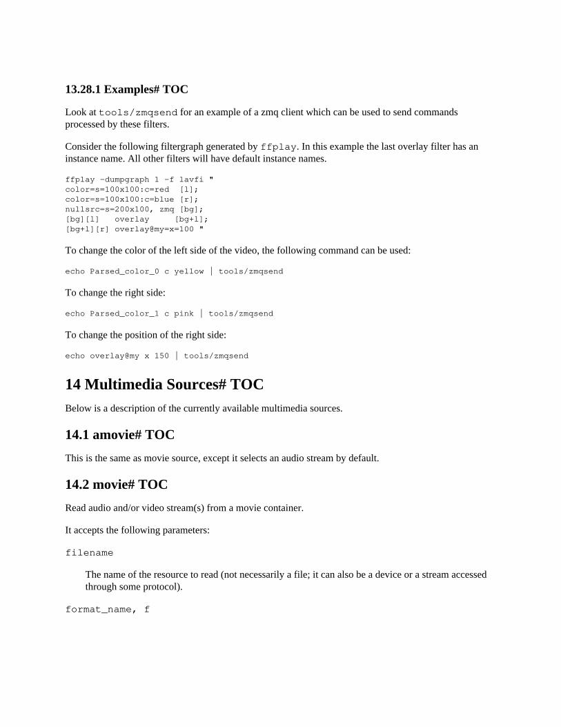
13.28.1 Examples# TOC
Look at tools/zmqsend for an example of a zmq client which can be used to send commandsprocessed by these filters.
Consider the following filtergraph generated by ffplay. In this example the last overlay filter has aninstance name. All other filters will have default instance names.
ffplay -dumpgraph 1 -f lavfi "color=s=100x100:c=red [l];color=s=100x100:c=blue [r];nullsrc=s=200x100, zmq [bg];[bg][l] overlay [bg+l];[bg+l][r] overlay@my=x=100 "
To change the color of the left side of the video, the following command can be used:
echo Parsed_color_0 c yellow | tools/zmqsend
To change the right side:
echo Parsed_color_1 c pink | tools/zmqsend
To change the position of the right side:
echo overlay@my x 150 | tools/zmqsend
14 Multimedia Sources# TOCBelow is a description of the currently available multimedia sources.
14.1 amovie# TOC
This is the same as movie source, except it selects an audio stream by default.
14.2 movie# TOC
Read audio and/or video stream(s) from a movie container.
It accepts the following parameters:
filename
The name of the resource to read (not necessarily a file; it can also be a device or a stream accessedthrough some protocol).
format_name, f
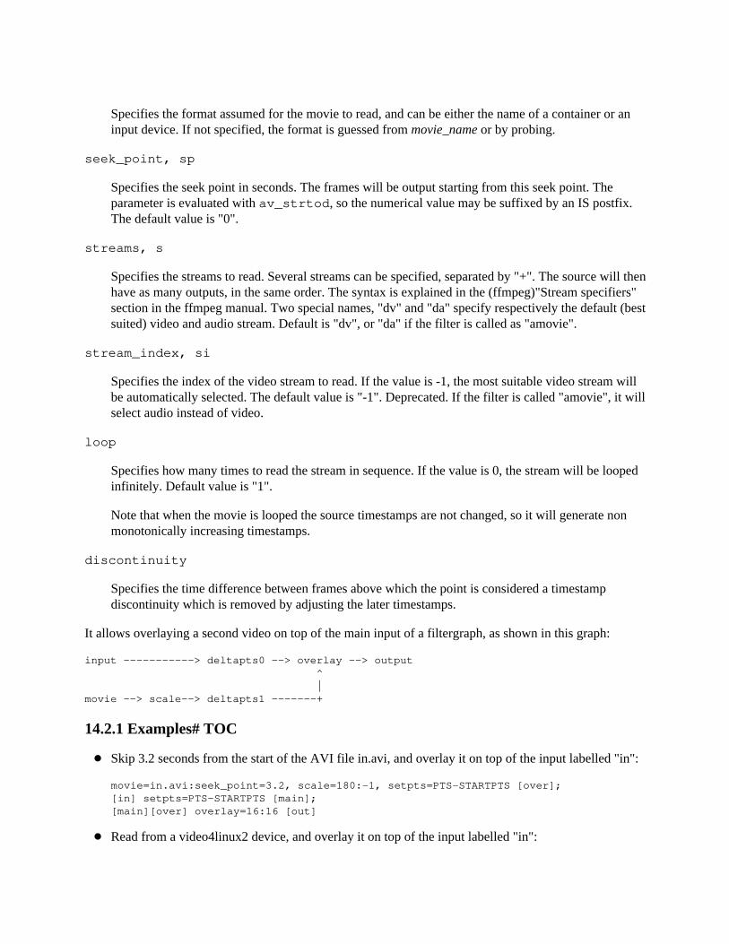
Specifies the format assumed for the movie to read, and can be either the name of a container or aninput device. If not specified, the format is guessed from movie_name or by probing.
seek_point, sp
Specifies the seek point in seconds. The frames will be output starting from this seek point. Theparameter is evaluated with av_strtod, so the numerical value may be suffixed by an IS postfix.The default value is "0".
streams, s
Specifies the streams to read. Several streams can be specified, separated by "+". The source will thenhave as many outputs, in the same order. The syntax is explained in the (ffmpeg)"Stream specifiers"section in the ffmpeg manual. Two special names, "dv" and "da" specify respectively the default (bestsuited) video and audio stream. Default is "dv", or "da" if the filter is called as "amovie".
stream_index, si
Specifies the index of the video stream to read. If the value is -1, the most suitable video stream willbe automatically selected. The default value is "-1". Deprecated. If the filter is called "amovie", it willselect audio instead of video.
loop
Specifies how many times to read the stream in sequence. If the value is 0, the stream will be loopedinfinitely. Default value is "1".
Note that when the movie is looped the source timestamps are not changed, so it will generate nonmonotonically increasing timestamps.
discontinuity
Specifies the time difference between frames above which the point is considered a timestampdiscontinuity which is removed by adjusting the later timestamps.
It allows overlaying a second video on top of the main input of a filtergraph, as shown in this graph:
input -----------> deltapts0 --> overlay --> output ^ |movie --> scale--> deltapts1 -------+
14.2.1 Examples# TOC
Skip 3.2 seconds from the start of the AVI file in.avi, and overlay it on top of the input labelled "in":
movie=in.avi:seek_point=3.2, scale=180:-1, setpts=PTS-STARTPTS [over];[in] setpts=PTS-STARTPTS [main];[main][over] overlay=16:16 [out]
Read from a video4linux2 device, and overlay it on top of the input labelled "in":
movie=/dev/video0:f=video4linux2, scale=180:-1, setpts=PTS-STARTPTS [over];[in] setpts=PTS-STARTPTS [main];[main][over] overlay=16:16 [out]
Read the first video stream and the audio stream with id 0x81 from dvd.vob; the video is connected tothe pad named "video" and the audio is connected to the pad named "audio":
movie=dvd.vob:s=v:0+#0x81 [video] [audio]
14.2.2 Commands# TOC
Both movie and amovie support the following commands:
seek
Perform seek using "av_seek_frame". The syntax is: seek stream_index|timestamp|flags
stream_index: If stream_index is -1, a default stream is selected, and timestamp is automaticallyconverted from AV_TIME_BASE units to the stream specific time_base.timestamp: Timestamp in AVStream.time_base units or, if no stream is specified, inAV_TIME_BASE units.flags: Flags which select direction and seeking mode.
get_duration
Get movie duration in AV_TIME_BASE units.
15 See Also# TOCffmpeg, ffplay, ffprobe, libavfilter
16 Authors# TOCThe FFmpeg developers.
For details about the authorship, see the Git history of the project (git://source.ffmpeg.org/ffmpeg), e.g. bytyping the command git log in the FFmpeg source directory, or browsing the online repository at http://source.ffmpeg.org.
Maintainers for the specific components are listed in the file MAINTAINERS in the source code tree.
This document was generated using makeinfo.


![[BEST]Ffmpeg Tutorial](https://static.fdocuments.in/doc/165x107/5477b7bb5906b59b318b4661/bestffmpeg-tutorial.jpg)