FF HSE & IE - Fieldbus Foundation · 3 © 2007 Fieldbus Foundation Foundation Fieldbus HSE HSE for...
38
© 2007 Fieldbus Foundation TAN Aik Hong Regional Key Account Manager Belden-Hirschmann (Singapore) Fieldbus Foundation – India Marketing Committee Technology Event Fieldbus Foundation ISA EXPO – 2007, Pragati Maidan, New-Delhi
Transcript of FF HSE & IE - Fieldbus Foundation · 3 © 2007 Fieldbus Foundation Foundation Fieldbus HSE HSE for...

© 2007 Fieldbus Foundation
TAN Aik HongRegional Key Account ManagerBelden-Hirschmann (Singapore)
Fieldbus Foundation – India Marketing Committee
Technology Event
Fieldbus Foundation
ISA EXPO – 2007,
Pragati Maidan, New-Delhi
2© 2007 Fieldbus Foundation
FOUNDATION FIELDBUS
HSE

3© 2007 Fieldbus Foundation
Foundation Fieldbus HSEHSE for use as a control backboneHSE enhances access to H1 technology via Linking Devices (LD)HSE uses standard Fast ETHERNET (IEEE802.3u)
Preserve all H1 functions and carry H1 servicesHigh speed transfer/huge bandwidthCommercial off the shelf (COTS) Ethernet components
Redundancy on the network level
LD
Controller
HSE
H1 segment
PLC Workstations
LDH1 segment
RIO
HSE RIO* In preparation

4© 2007 Fieldbus Foundation
FOUNDATION Fieldbus ArchitectureISO/OSI Model H1 HSE
User LayerUser Layer
EthernetPhysical
Data Link
Network
Transport
Session
Presentation
1
2
6
5
4
3
7
H1 @ 31.25 kbit/s
H1 DLL (LM/LAS)
FAS
FMSApplication FDA
TCP/UDP
IP
HSE @ 100MBPS
IEEE802 DLL

5© 2007 Fieldbus Foundation
Standard Ethernet and Automation ProtocolsL5 protocol necessary for automation communication,L3 and L4 protocol necessary for realtime applications.
Application Programming Interface (API)
Established standards of the IT world
Data Link (2)Physical (1) Ethernet IEEE 802.3
ARP ICMP
UDP
SNMPHTTP DNS FTP???Middleware(5-7)
TCP ???Transport(4)
Network(3) IP ???
New Industrial-Ethernet protocols

6© 2007 Fieldbus Foundation
Industrial Automation ProtocolsEthernet/IP
By ODVA (Open DeviceNet Vendor Association)In higher protocol layers ControlNet/DeviceNet
Modbus TCP/IPIDA (Interface for Distributed Automation) /modbus.org
Technology: compatible to ModBus/TCP
PROFInetBy PNO (Profibus Nutzer Organisation)Technology: Take-over of complete Profibus
®
PROCESS FIELD BUS

7© 2007 Fieldbus Foundation
H1 Physical Layer

8© 2007 Fieldbus Foundation
FF standard
H1 EthernetSpeed 31.25 kbit/s 100 Mbit/sDistance 1900 m 100 m Two-wire Yes No Multidrop Yes No Bus power Yes No Intrinsically safe Yes No Media redundancy No Yes Deterministic Yes Yes

9© 2007 Fieldbus Foundation
Key Cable ParametersIEC 61158-2 / ISA-SP 50 Standard Type A Cable (our 3076F) Type B Cable (our 3077F)Impedance 100 Ohms +/- 20 100 Ohms +/- 30Capacitance Unbalance 4 nF/km 6 nF/kmConductor DC Resistance 24 Ohms/km 56 Ohms/kmAttenuation @ 39 kHz 3 dB/km 5 dB/kmMax. Propagation Delay: 1.7 us/kmMinimum Shield Coverage 90% 90%Conductor Size 18 AWG 22 AWGMax network length up to 1900m 1200m
Type A Cable Type B Cable
Impedance 100 Ω @ 31.25 kHz
Capacitance Unbalance < 4 ηF/km
Conductor DC Resistance < 24 Ω/km
Cable Shielding > 90% coverage
CcS
Ccc
Insulation
Drain wire
Shield
CcS
Conductor
Inductance & resistance
Centricity

10© 2007 Fieldbus Foundation
Bus Power
R
PowerPowerSupplySupply
Fieldbus Fieldbus CardCard
FieldField ControlControl StationStation
WorkstationWorkstation
BackboneBackbone--networknetwork
Zone 1Zone 1
Zone 0Zone 0EexEex ia IICia IIC
EExEEx(e)(e) EExEEx(e)(e)Power Budget
400 mA, 24V (non-IS)
215 mA, 13V (FNICO/Zone 2)
100 mA, 12.8V (IS FISCO, Zone 1)
70 mA, 10.6V (IS Entity)
Bus trunkline power the Fieldbarriers

11© 2007 Fieldbus Foundation
Ethernet Physical Layer

12© 2007 Fieldbus Foundation
OSI Reference Model (Physical)
Hub/RepeaterMedia Converter
Physical
Data Link
Network
Transport
Session
Presentation
Application
1
6
5
4
3
2
7
The Physical Layer defines the physics of getting a message from one device to another. Is responsible for an error free transmissionConverts bits into signals for outgoing messages and signals into bits for incoming onesThis is the most important area in terms of troubleshooting and operations
HIRSCHMANN HIRSCHMANN

13© 2007 Fieldbus Foundation
Network Topologies - Bus
min. 0.5 mSegmentmax. 185 m
BNC T-JointTerminator 50 Ω
Ethernet 10 Mbit/s –10Base2
min. 2.5 m
Transceiver cablemax. 50 m
Terminator 50 Ω
Transceiver
Segmentmax. 500 m
Ethernet 10 Mbit/s –10Base5

14© 2007 Fieldbus Foundation
Network Topologies - Star

15© 2007 Fieldbus Foundation
Network Topologies - Tree
HIRSCHMANN
HIRSCHMANNHIRSCHMANNHIRSCHMANN HIRSCHMANNHIRSCHMANNHIRSCHMANN
HIRSCHMANN HIRSCHMANNHIRSCHMANNHIRSCHMANN

16© 2007 Fieldbus Foundation
Network Topologies - Ring
HIRSCHMANN
HIRSCHMANN
HIRSCHMANNHIRSCHMANNHIRSCHMANN
HIRSCHMANN

17© 2007 Fieldbus Foundation
Network Topologies - Mesh
HIRSCHMANN HIRSCHMANN
HIRSCHMANNHIRSCHMANNHIRSCHMANN
HIRSCHMANN

18© 2007 Fieldbus Foundation
Twisted Pair
Categorization of TP cable: Cat. 3: min. transmission frequency 20 MHz Cat. 5: min. transmission frequency 125 MHz Cat. 6: min. transmission frequency 250 MHz Cat. 7: min. transmission frequency 600 MHz

19© 2007 Fieldbus Foundation
Twisted-Pair – Industrial Connectors
Currently no industry suitable connector standardized by IEEEDemands: mechanical stability, IP protection (IP64 or IP67), stable against vibrationsProprietary solutions:
DB-9: large installed baseM12: suggested by IAONA for Ethernet, well-known in fieldbus areaVS-RJ45: RJ45 adaptedRJ Lnxx: sleeve nut over RJ45
M12
20© 2007 Fieldbus Foundation
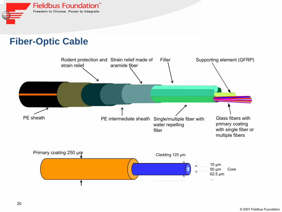
Fiber-Optic Cable
PE intermediate sheath Single/multiple fiber withwater repellingfiller
FillerStrain relief made ofaramide fiber
Rodent protection andstrain relief
PE sheath Glass fibers withprimary coatingwith single fiber ormultiple fibers
Supporting element (GFRP)
Primary coating 250 µm
10 µm50 µm Core62.5 µm...
Cladding 125 µm
21© 2007 Fieldbus Foundation
Fiber Optic transmissionFiber optic cable has huge advantages over copper
It’s immune to Electromagnetic InterferenceSupport of long distances
Fiber is made fromGlass – High quality, used for long distances or high speedPlastic – Cheaper, used for short distances and low speedGlass core + plastic cladding – compromize, fieldbusses only
There are 3 basic light sourcesLEDs – low cost, used for MMFELEDs - medium cost, used for SMF, cheaper than LDs, no Laser protection measures neededLaser, Laser Diodes LD – used with SMF over long distances

22© 2007 Fieldbus Foundation
Fiber types 1: Multimode FiberBecause of the high dispersion, multimode fiber is only used for short distances.LEDs for glass fiber use either 850 nm or 1300 nm wavelength for transmission
Cladding diameter 125 µm
Core diameter 50µm or 62.5µm

23© 2007 Fieldbus Foundation
Fiber types 2: Singlemode FiberCapable of transmission rates of several Tbit/sUse of ELEDs at 1300 nm wavelength till about 30 km, for longer distances lasers/LDs with 1550 nm as transmittersQuoted as between 8/125 µm and 10/125 µm cable, depending on manufacturer
Cladding diameter 125µm Core diameter 8µm or 10µm
24© 2007 Fieldbus Foundation
Ethernet Data Link Layer

25© 2007 Fieldbus Foundation
OSI Reference Model (Data Link)The Data Link Layer provides the rules for converting electrical signals to data, error checking, physical addressing and media access control.Handles the delivery of frames from sender to receiver through the physical layer.
Physical
Network
Transport
Session
Presentation
Application
1
6
5
4
3
2
7
Data Link
SwitchesHIRSCHMANN
HIRSCHMANNHIRSCHMANNHIRSCHMANN

26© 2007 Fieldbus Foundation
MAC and LLC LayerApplication72b: Logical Link Control (LLC)
Link make and break, packet traffic control, packet sequencing, packet acknowledgement
LLC offers link control independent of medium. 2a: Medium Access Control (MAC)
Functions in send directionFunctions in receive direction
Presentation6
Session5
Transport4
Network
1
3
2 Data Link
Physical
LLC
MAC
2b
2a
27© 2007 Fieldbus Foundation
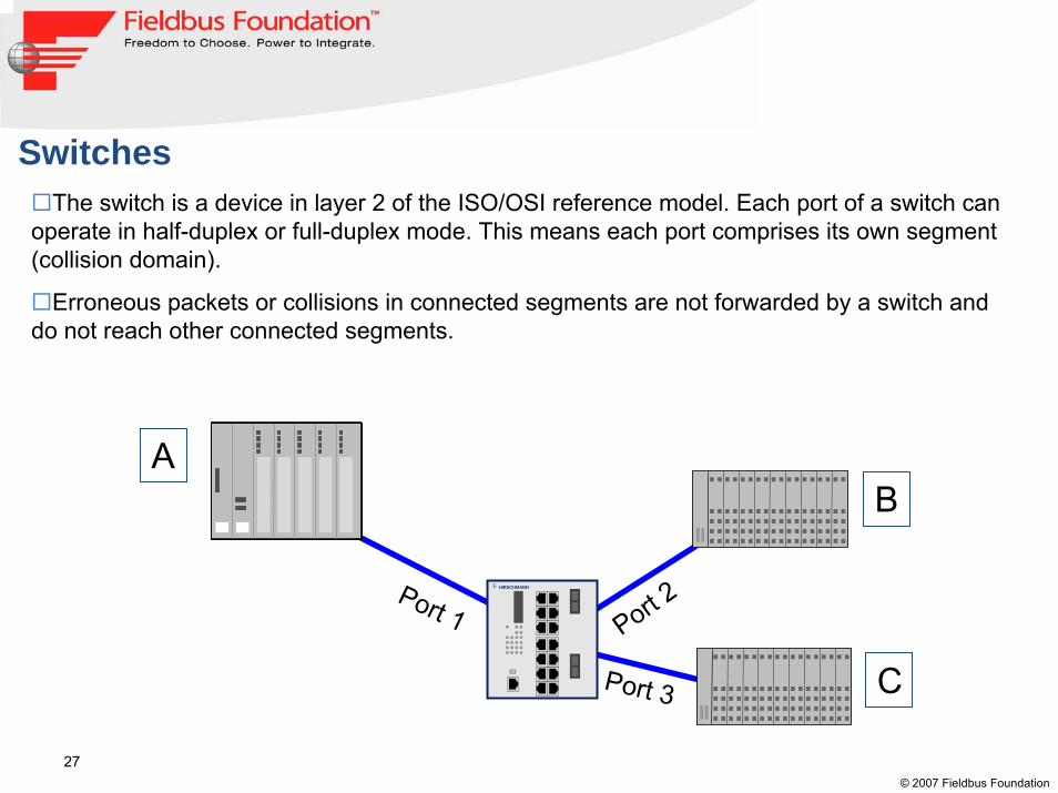
SwitchesThe switch is a device in layer 2 of the ISO/OSI reference model. Each port of a switch can
operate in half-duplex or full-duplex mode. This means each port comprises its own segment (collision domain).
Erroneous packets or collisions in connected segments are not forwarded by a switch and do not reach other connected segments.
AB
C
Port 1 Port 2
Port 3
HIRSCHMANN

28© 2007 Fieldbus Foundation
Industrial Ethernet

29© 2007 Fieldbus Foundation
ETHERNET: The PresentETHERNET today is not the same when it was invented 30 years ago
What’s the improvements?
- Higher bandwidth -10Mbit/100Mbit/1Gbit/10G
- Full-duplex communication → without collisions
- Switching
- Prioritization and flow control
- VLANs - Virtual Local Area Networks

30© 2007 Fieldbus Foundation
Why Industrial ETHERNET?• The fieldbuses available on the market use different types of physical
transmission; as a result bus-specific infrastructure components are necessary and the interface to the higher level networks requires so-called “gateways”.
• Ethernet offers a dramatic increase in bandwidth compared to fieldbuses (e.g. Profibus DP up to 12 Mbit/s – Ethernet up to 10Gigabit/s).
• Ethernet makes vertical integration possible(From ERP down to the station controller).
• Ethernet is an open protocol.
• The majority of fieldbus manufacturers have developed their own protocols that build on standard Ethernet: Modbus/TCP, EtherNet/IP, ProfiNet, FF HSE, Powerlink.

31© 2007 Fieldbus Foundation
ETHERNET: Office vs IndustryOffice Industrial
Cabling depends on industrial installationBasic installation Fixed basic installation in the building, flexible installation of devices at the workplace
Top hat rail / clamp
Connectors No specific requirements IP20, IP30, IP67 with confection in the fieldRedundant, often ring topologiesTopology Mostly star networks at the tertiary level;
hierarchical trees Bus topologies for fieldbusesTemperature Normal Extended range from -40~+70oC, natural
convectionHumidity Normal Rel. humidity up to 95% (non-condensing)Dust Low PossibleMechanical Low Shock and vibration:
SPS standards IEC 1131-2, IEC 60068Chemical No specific requirements PossibleElectrical No specific requirements EMI: EN50022, EN50082-2, FCC part15 (Class
B), IEC 1000-4-2, IEC 1000-4-6, IEC 1000-4-4, EN61000
EMC Low HighSize of data packets Short LargeAvailability Medium HighMTBF medium 20~100 yearsTransmission Mostly acyclic Cyclic & acyclicReal-time capability Mostly not required Required
Data
Environment
Installation
32© 2007 Fieldbus Foundation
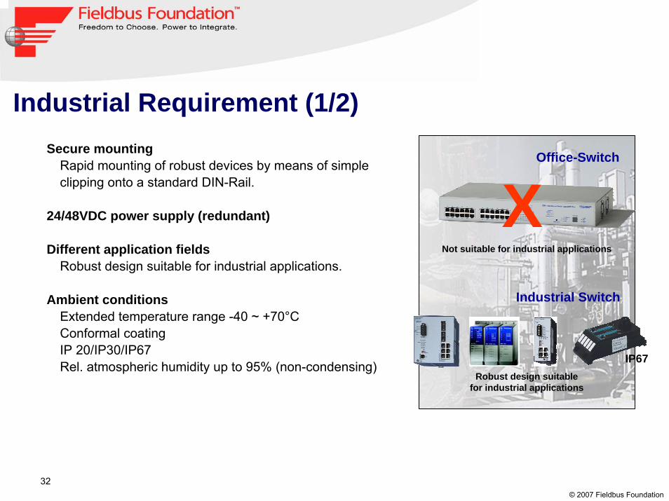
Industrial Requirement (1/2)
Office-Switch
Not suitable for industrial applications
XIndustrial Switch
Secure mountingRapid mounting of robust devices by means of simple clipping onto a standard DIN-Rail.
24/48VDC power supply (redundant)
Different application fieldsRobust design suitable for industrial applications.
Ambient conditionsExtended temperature range -40 ~ +70°CConformal coatingIP 20/IP30/IP67Rel. atmospheric humidity up to 95% (non-condensing)
IP67Robust design suitable
for industrial applications

33© 2007 Fieldbus Foundation
Mechanical stabilityVibration, shock and free-fall tests in accordance with PLC standards EN 61131-2 (IEC 1131-2:1992), IEC 60068.
Electrical requirementEMI: EN 50022, EN 50082-2, FCC Part 15 (Class B)IEC 1000-4-2, IEC 1000-4-6, IEC 1000-4-4, EN 61000.
Certifications / ApprovalsCE, cUL 60950, cUL 508cUL 1604 Class 1 Div 2 (A, B, C, D) or FM 3611 Class I Div 2ATEX 100a Zone 2Maritime applications, e.g., GL (Germanischer Lloyd), DNVSubstation IEC61850
High MTBF (Mean Time Between Failure)Approx. from 20 to >100 years, in comparison with office devices with typically 3 to 5 years.(Fan-less design)
Industrial Requirement (2/2)

34© 2007 Fieldbus Foundation
ETHERNET: Office vs Industry
Home/Office product- Link status LED not visible- 110/230 V AC- Unprofessional mounting using
cable ties
Industrial-graded product- Link status easily monitored- 24 V DC- DIN-rail mounting
35© 2007 Fieldbus Foundation
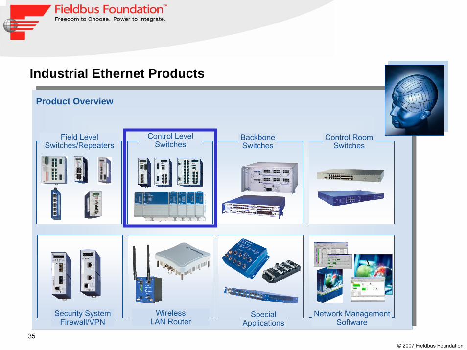
Product Overview
Network ManagementSoftware
Security SystemFirewall/VPN
Control Room Switches
Control Level Switches
Field Level Switches/Repeaters
Industrial Ethernet Products
Wireless LAN Router
BackboneSwitches
SpecialApplications

36© 2007 Fieldbus Foundation
Control Level Switches / Openrail Compact
2x Gigabit-ETHERNET uplinks
Twisted Pair /RJ45 (10/100Mbit/s)Twisted Pair /M12 (10/100Mbit/s)Multimode/SC (100Mbit/s)Multimode/ST (100Mbit/s)Singlemode/SC (100Mbit/s)Singlemode LH /SC(100Mbit/s)SFP slot (1000Mbit/s)
Twisted Pair /RJ45 (10/100Mbit/s)Twisted Pair /M12 (10/100Mbit/s)
Compact switch (Rail)
2x Fast-ETHERNET uplinksRS 20
RS 30
04
08
16
24
4x 100 Mbit/s
8x 100 Mbit/s16x 100 Mbit/s24x 100 Mbit/s
Number of Fast-ETHERNET ports
00
02
No Gigabit-ETHERNET port
2x 1000 Mbit/s
Number of Gigabit-ETHERNET ports
T1
T5
M2
M4
S2
L2
06
Media type uplink port 1
T1
T5
M2
M4
S2
L2
06
Multimode/SC (100Mbit/s)Multimode/ST (100Mbit/s)Singlemode/SC (100Mbit/s)Singlemode LH/SC (100Mbit/s)SFP slot (1000Mbit/s)
Media type uplink port 1
RS 30 24 O6 T1 S D A E H H 01.0Design FE-ports GE-ports Uplink port 1 Uplink port 2 Temperature Power Supply Approvals Software Configuration OEM type Software release
02
01.0 Software release 1.0Software release
H
X
StandardCustomer specific
OEM type / Configuration
E
P
EnhancedRemote access, diagnosis, filters, redundancy
Professional:Enhanced software plus security,extended diagnosis and redundancy
Software version
A
B
cUL508, cUL1604 Class1 Div.2
cUL508, cUL1604 Class1 Div.2, GLSubstation IEC61850,Railway standard EN 50121-4/EN 50155ATEX 100a Zone 2
Approvals
Power supply
D 9,6 - 60V DC and 18 - 30 V AC(only Rail)
S
T
Standard 0°C up to +60°C
Extended -40°C up to +70°C
Temperature range
optio
nal
HcUL508, cUL1604 Class1 Div.2, GLSubstation IEC61850,Railway standard EN 50121-4
E Extended -40°C up to +70°Cinclusive Conformal Coating

37© 2007 Fieldbus Foundation
Control Level Switches / Openrail Compact

38© 2007 Fieldbus Foundation
Thank you for your attention!