FF Gladiator Plan Package.pdf - 0201.nccdn.net · FrogFlite Gloster Gladiator Modifications to...
17
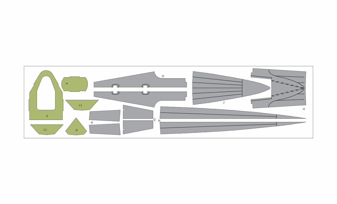
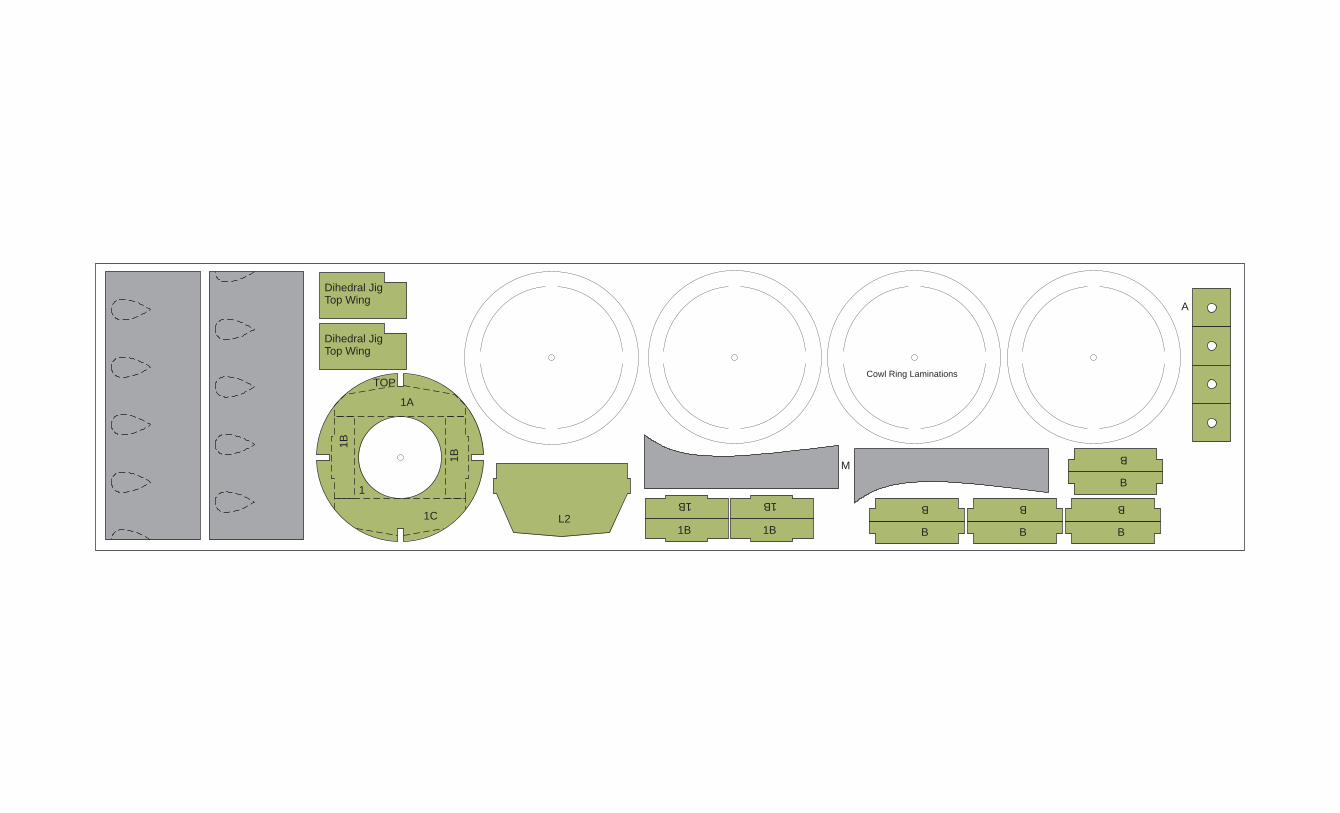
There are several notes I need to provide to aid you with the enclosed package. The original kits used 1/16" balsa. Since I wanted to print these directly on balsa sheet I developed the parts for 1/32" balsa sheet. As a result, some of the parts have been drawn to allow for cross grain laminations. The fuselage formers are a good example. This works fine as long as you are using 1/32" sheet stock. If you do not have a printer that will allow direct printing on the balsa, consider using the iron on T- shirt transfer paper layouts provided via the parmodels.com web site. This material can be printed on any color inkjet printer. You can then transfer the part graphics to balsa sheet of any thickness using a regular clothes iron. I like to use a removable nose for winding. The parts have been drawn with this in mind. The nose former has been drawn so a removable nose button can be used. A template has been provided to aid in forming the nose button. The kit included reinforcements for the rear motor peg. The parts in this package include the same rear motor peg reinforcement parts. The only difference is two sets of those parts are included to allow for models build from 1/32” balsa. This has proven to be plenty strong for a fully wound motor of 1/8" Tan rubber. A piece of 3/32” OD aluminum tubing is used for the rear motor peg. A few modifications to the original kit structure have been included. The original kit used solid blocks on the forward portion of the fuselage top and bottom. These have been replaces with sheet wood parts. That allows the color and markings to be consistent on the model and also helps eliminate a bit of weight. All of the modifications are shown on a supplemental illustration sheets. The original kit did not include landing gear leg covers. This drawing package does include them for the gear legs so the finished model will more closely resemble the box art. The original kit had markings printed on the balsa pieces with a bare balsa background. This reproduction drawing package uses the original kit markings with color added to the bare balsa areas. I do hope you build and enjoy a model from this plan package. Paul Bradley
Transcript of FF Gladiator Plan Package.pdf - 0201.nccdn.net · FrogFlite Gloster Gladiator Modifications to...
There are several notes I need to provide to aid you with the enclosed package. The original kits used 1/16" balsa. Since I wanted to print these directly on balsa sheet I developed the parts for 1/32" balsa sheet. As a result, some of the parts have been drawn to allow for cross grain laminations. The fuselage formers are a good example. This works fine as long as you are using 1/32" sheet stock.
If you do not have a printer that will allow direct printing on the balsa, consider using the iron on T-shirt transfer paper layouts provided via the parmodels.com web site. This material can be printed on any color inkjet printer. You can then transfer the part graphics to balsa sheet of any thickness using a regular clothes iron. I like to use a removable nose for winding. The parts have been drawn with this in mind. The nose former has been drawn so a removable nose button can be used. A template has been provided to aid in forming the nose button.
The kit included reinforcements for the rear motor peg. The parts in this package include the same rear motor peg reinforcement parts. The only difference is two sets of those parts are included to allow for models build from 1/32” balsa. This has proven to be plenty strong for a fully wound motor of 1/8" Tan rubber. A piece of 3/32” OD aluminum tubing is used for the rear motor peg.
A few modifications to the original kit structure have been included. The original kit used solid blocks on the forward portion of the fuselage top and bottom. These have been replaces with sheet wood parts. That allows the color and markings to be consistent on the model and also helps eliminate a bit of weight. All of the modifications are shown on a supplemental illustration sheets.
The original kit did not include landing gear leg covers. This drawing package does include them for the gear legs so the finished model will more closely resemble the box art.
The original kit had markings printed on the balsa pieces with a bare balsa background. This reproduction drawing package uses the original kit markings with color added to the bare balsa areas. I do hope you build and enjoy a model from this plan package.
Paul Bradley

K
K
I
I
P

LG Covers
Nose ButtonKeys
4
6
C
C
G
Q
R
H
J
N
3
6
DL1
L1
Cowl Ring Laminations
1B 1B
1B 1B
B B B
B
B B B
B
M
A
L2
Dihedral JigTop Wing
Dihedral JigTop Wing
1
1A
1C
1B
1B
TOP

Incidence Jig
Incidence Jig
Interplane Struts - Rear
Interplane Struts - Front
Center Section Struts
Center Section Struts
Bott WingDihedral Jig
Bott WingDihedral Jig
Exhaust
Exhaust
L2
X
1
TO
P

3
5

5
2A
2A
2C2C
E

O4
2B
2B
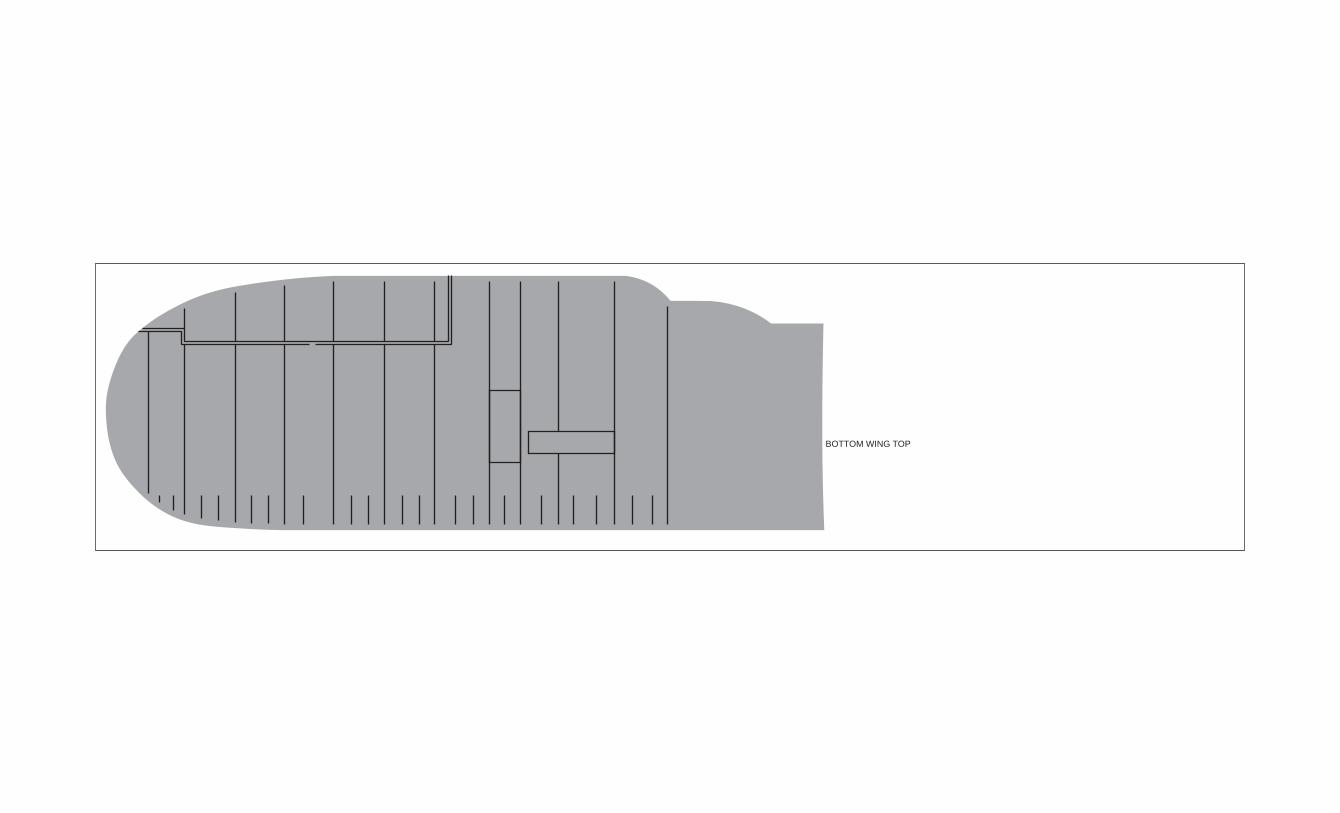
BOTTOM WING TOP

Forward Cowl
Former
1A
1A
1C
1C

BOTTOM WING TOP
FrogFlite Gloster Gladiator
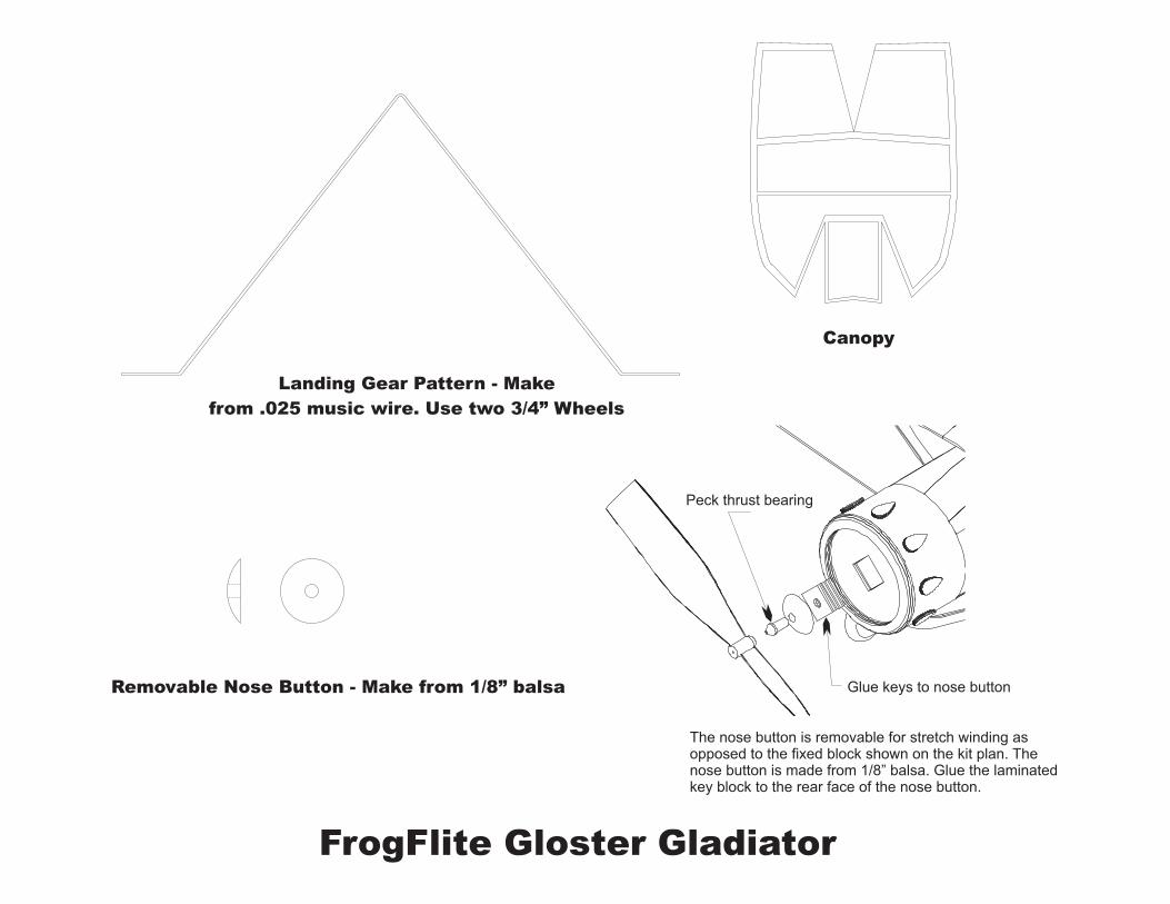
Landing Gear Pattern - Make
from .025 music wire. Use two 3/4” Wheels
Canopy
Removable Nose Button - Make from 1/8” balsa
The nose button is removable for stretch winding asopposed to the fixed block shown on the kit plan. Thenose button is made from 1/8” balsa. Glue the laminatedkey block to the rear face of the nose button.
Peck thrust bearing
Glue keys to nose button
FrogFlite Gloster Gladiator
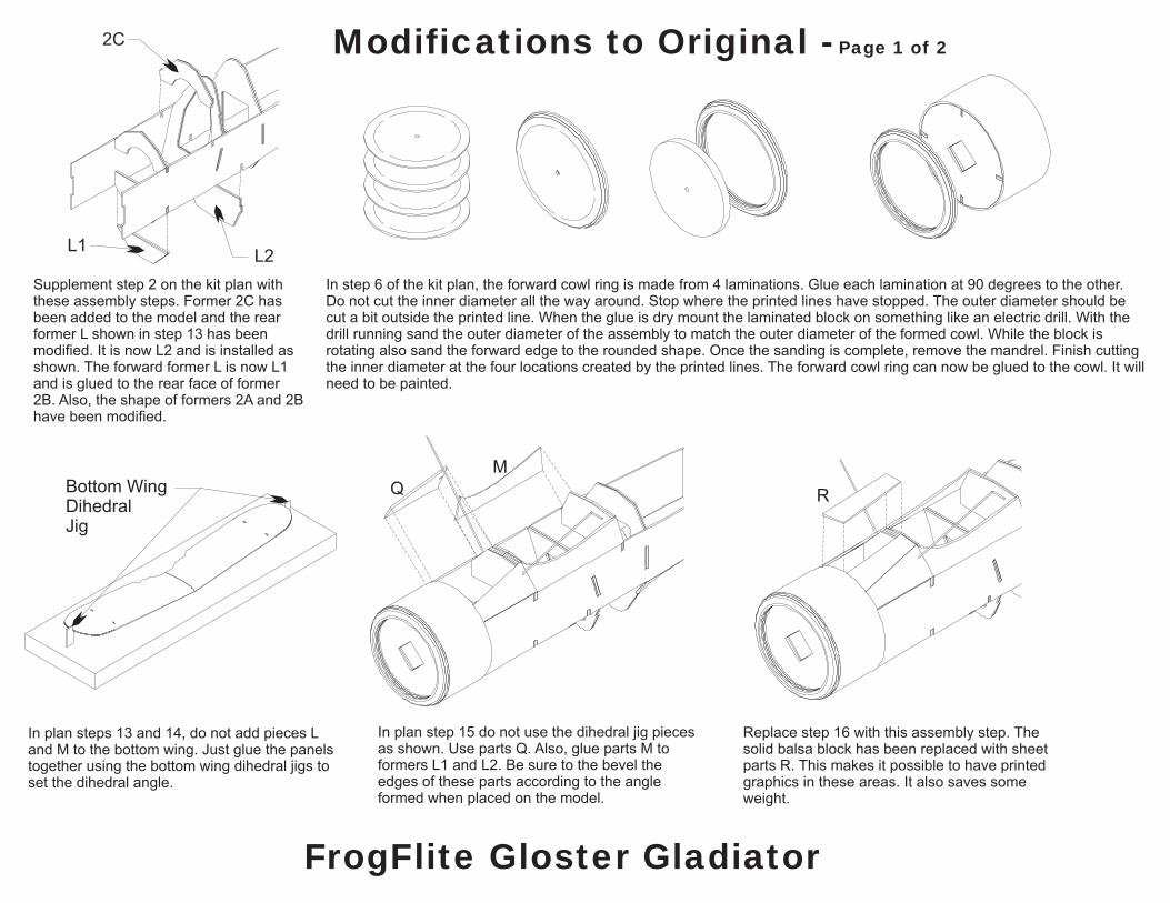
Modifications to Original - Page 1 of 2
Supplement step 2 on the kit plan withthese assembly steps. Former 2C hasbeen added to the model and the rearformer L shown in step 13 has beenmodified. It is now L2 and is installed asshown. The forward former L is now L1and is glued to the rear face of former2B. Also, the shape of formers 2A and 2Bhave been modified.
In plan steps 13 and 14, do not add pieces Land M to the bottom wing. Just glue the panelstogether using the bottom wing dihedral jigs toset the dihedral angle.
In step 6 of the kit plan, the forward cowl ring is made from 4 laminations. Glue each lamination at 90 degrees to the other.Do not cut the inner diameter all the way around. Stop where the printed lines have stopped. The outer diameter should becut a bit outside the printed line. When the glue is dry mount the laminated block on something like an electric drill. With thedrill running sand the outer diameter of the assembly to match the outer diameter of the formed cowl. While the block isrotating also sand the forward edge to the rounded shape. Once the sanding is complete, remove the mandrel. Finish cuttingthe inner diameter at the four locations created by the printed lines. The forward cowl ring can now be glued to the cowl. It willneed to be painted.
In plan step 15 do not use the dihedral jig piecesas shown. Use parts Q. Also, glue parts M toformers L1 and L2. Be sure to the bevel theedges of these parts according to the angleformed when placed on the model.
Replace step 16 with this assembly step. Thesolid balsa block has been replaced with sheetparts R. This makes it possible to have printedgraphics in these areas. It also saves someweight.
2C
L2L1
Q
M
RBottom WingDihedralJig

Modifications to Original - Page 2 of 2
Replace steps 17 and 18 with this assembly step.The solid balsa block has been replaced withsheet parts I. This makes it possible to haveprinted graphics in these areas. It also savessome weight.
The kit plan illustration of the model showslanding gear covers. They were not included inthe kit. Landing gear covers have been includedin the reproduction model part set and areinstalled as shown.
The kit plan does not specifically show theinstallation of canopy parts K. They are identifiedon the 3D illustration but not mentioned in theassembly steps. Parts K should be installedbefore the plastic canopy as shown.
Plan step 22 calls for the tail wheel to be installed.The tail wheel has been modified to be consistentwith the other models in the Quick Build series.This is easier to install and should be morerobust. A placement guide has been printed onpart P.
For kit plan steps 23 through 26 the top wing is builtand assembled on the model. It is felt that assemblingthe top wing completely before it is installed on themodel is much easier and accurate. As a result extraribs have been drawn for use on the outer wing panelroots when forming the dihedral joints. Disregard theplan references to butt strap pieces. They are not used.Be sure to use the top wing dihedral jigs.
I
Top WingDihedralJig
Bevel
K
K