FETS RFQ Design Review - Imperial College London RFQ Design Review.pdf · FETS RFQ Design Review...
43
2011 Peter Savage Imperial College 10/12/2011 FETS RFQ Design Review
-
Upload
nguyendung -
Category
Documents
-
view
214 -
download
0
Transcript of FETS RFQ Design Review - Imperial College London RFQ Design Review.pdf · FETS RFQ Design Review...

2011
Peter Savage
Imperial College
10/12/2011
FETS RFQ Design Review

FETS RFQ Design Review
P. Savage, Imperial College Page 2
Present:
Amanda Brummitt Rutherford Appleton Laboratory
Alberto Garbayo Rutherford Appleton Laboratory
Scott Lawrie Rutherford Appleton Laboratory
Alan Letchford Rutherford Appleton Laboratory
Juergen Pozimski Imperial College London
Peter Savage Imperial College London

FETS RFQ Design Review
P. Savage, Imperial College Page 3
Table of Contents
Overview ............................................................................................................................................. 4
Design Philosophy ............................................................................................................................... 5
Transverse Profile ............................................................................................................................... 6
Longitudinal Profile ............................................................................................................................. 8
Major Vane........................................................................................................................................ 11
Minor Vane ....................................................................................................................................... 12
Datum System ................................................................................................................................... 13
MAJOR VANE .................................................................................................................................... 13
MINOR VANE ................................................................................................................................. 14
Frequency Modelling ........................................................................................................................ 15
Vacuum Port ..................................................................................................................................... 16
Vacuum seal ...................................................................................................................................... 19
Probe Port ......................................................................................................................................... 23
Tuners ............................................................................................................................................... 26
Finger Strip RF Seal ........................................................................................................................... 29
LONGITUDINAL AND TRANSVERSE JOINTS ............................................................................................... 29
TUNER AND PROBE PORTS ................................................................................................................... 30
Cooling Pockets ................................................................................................................................. 31
RFQ Alignment .................................................................................................................................. 35
Bulk Copper ....................................................................................................................................... 36
Low Energy End ................................................................................................................................. 38
High Energy End ................................................................................................................................ 39
Modulation Compensation ............................................................................................................... 40
Inspection .......................................................................................................................................... 42

FETS RFQ Design Review
P. Savage, Imperial College Page 4
Overview
A Radio Frequency Quadrupole (RFQ) can be used to accelerate an ion beam. In our case this RFQ
will be used to accelerate H- ions from 65keV to 3 MeV. It is part of the Front End Test Stand (FETS)
accelerator line being built in R8 at the Rutherford Laboratories.
Figure 1: One metre long RFQ – an assembly of two pairs of parts
Figure 2: Looking along the RFQ beam axis
The RFQ is an assembly of two major vanes (shown in brown) and two minor vanes (shown in yellow).

FETS RFQ Design Review
P. Savage, Imperial College Page 5
Design Philosophy
Many RFQs have been built to date with varying degrees of success. The tried and tested method is
to manufacture the RFQ as an assembly of parts. The complex internal geometry makes a build from
solid impractical with today’s machining technology.
The default method for joining the parts is vacuum brazing. This technique offers a number of
advantages including:
1. Results in one solid part.
2. Good vacuum seal.
3. Good RF seal.
4. High Q value.
5. Many joints made in one operation.
Some of the disadvantages include:
1. The RFQ cannot be dismantled if required.
2. Distortion of material due to high temperatures used during brazing.
3. Annealing of material due to high temperatures used.
4. Precise stress relieving cycles required during manufacture.
The most experienced RFQ builders in the world cannot guarantee successful vacuum brazing and,
even when successful sometimes RFQs do not perform to the designed specification. For these
reasons the FETS team decided to pursue an RFQ design that allowed the assembled parts to be
dismantled. Reasons for dismantling could include:
1. Realignment
2. Cleaning
3. Removing surface irregularities caused by sparking
4. Re-machining to change operating frequency
The price to pay for this flexibility of design includes:
1. Challenging vacuum seal.
2. Potentially lower Q value

FETS RFQ Design Review
P. Savage, Imperial College Page 6
Transverse Profile
Both the major and minor vanes use one 2D sketch to define their shape. The sketch is fully
constrained to the centre origin that represents the beam axis. The result is that if one parameter is
changed in the spreadsheet the assembly grows or shrinks transversally around the beam axis.
Figure 3: 2D sketch that controls the geometry of the major and minor vanes

FETS RFQ Design Review
P. Savage, Imperial College Page 7
Figure 4: End view of RFQ section 1
Why is the RFQ this shape transversally?
Radiofrequency currents flow radially in the four quadrants producing two opposing vane tips of
positive voltage and two opposing vane tips of negative voltage at any one time. This produces a
quadrupole focusing or defocusing effect on the beam. One half cycle later the voltages change sign,
reversing the focusing. The overall focusing effect keeps the beam within the small volume between
the vane tips.
The importance of size and alignment
To keep the RFQ running at the designed frequency (324MHz) the size of the transverse profile and
the alignment of the major and minor vanes must be tightly controlled. If the size deviates too far
from the designed specification then we risk exciting dipole modes (with frequencies close to
324MHz) in addition to the desired quadrupole mode. Similarly if the alignment isn’t within
specification then the asymmetry will encourage the excitation of dipole modes.

FETS RFQ Design Review
P. Savage, Imperial College Page 8
Longitudinal Profile
Looking along the length of the RFQ the transverse profile remains largely the same. The changes
are at the vane tips (ignoring external features).
Figure 5: Three-quarter view of RFQ section 3
Figure 6: Close-up view showing the vane tip modulations that produce the longitudinal electric field.

FETS RFQ Design Review
P. Savage, Imperial College Page 9
Figure n: Close-up view showing the vane tip modulations that produce the longitudinal electric
field.
What do the vane modulations do?
Figure 7: Sequence to show how the vane modulations accelerate a particle bunch – Simon Jolly
How were they generated?
Alan Letchford used his RFQSIM code to generate the parameters a, ma, r0 and rho. These
parameters control the shape of the RFQ modulations and hence they control the acceleration
performance.
Simon Jolly wrote a Visual Basic script for Autodesk Inventor that takes the parameters from a
spreadsheet (RFQVaneParamsMaster.xls ) and generates a 2D spline. The spline is then revolved to
create a 3D rod (much like that used for a rod type RFQ). Some further manipulations are then
performed to generate a vane tip, see figure 8.

FETS RFQ Design Review
P. Savage, Imperial College Page 10
Figure 8: A vane tip with modulations
Simon then imported these vane modulation models into GPT and then later into COMSOL finite
element software to perform particle tracking simulations.
This modelling procedure allowed Simon Jolly to work on the particle tracking in parallel to Peter
Savage working on the mechanical design.

FETS RFQ Design Review
P. Savage, Imperial College Page 11
Major Vane
Major Vane Stock Finished part
Length (mm) 1050 1010,67
Width (mm) 270 260
Height (mm) 137 128,63
Mass (kg) 357 77
Material Copper C10100
Table 1: RFQ major vane sizes and weights
Figure 9: RFQ major vane – showing external features
Figure 10: RFQ major vane – showing internal features

FETS RFQ Design Review
P. Savage, Imperial College Page 12
Minor Vane
Minor Vane Stock Finished part
Length (mm) 1050 1010,67
Width (mm) 113 102,50
Height (mm) 137 128,63
Mass (kg) 148 29
Material Copper C10100
Table 2: RFQ minor vane sizes and weights
Figure 11: RFQ minor vane – showing external features
Figure 12: RFQ minor vane – showing internal vane

FETS RFQ Design Review
P. Savage, Imperial College Page 13
Datum System
MAJOR VANE
Datum Location Function
A Main face Primary machining reference B Side face Secondary machining reference C End face Tertiary machining reference With three datum planes the part is full constrained, i.e. there are no remaining degrees of freedom. What we need now is to refine the datum system to allow accurate positioning of the internal profile. By using external datum features as references for the position of the internal profile we have provided features that can be used during manufacture and assembly. D Interface planes (common zone) Control alignment of vanes during assembly E 1st dowel hole on A External longitudinal vane modulation reference F 2nd dowel hole on A G Line linking E and F (derived feature) Controls inner profile longitudinal alignment The manufacturer can mount the major vane onto a simple plate with two dowels at the correct spacing for datum holes E and F and that are aligned to the machine axis – see figure n. The position of one of the dowels can be clocked and recorded. Now the vane alignment and the start position of the vane modulations can be defined by the position of the first dowel centre and the derived axis between the two dowels centres. These external references can be used both for vane to vane alignment during assembly and for alignment of the assembled RFQ section onto the FETS. H Vacuum port centre J 450 faces K Probe port axis L Tuner port axis The remaining datums control the locations of external features.
Figure 13: Major vane with machining mounting plate

FETS RFQ Design Review
P. Savage, Imperial College Page 14
MINOR VANE
Datum Location Function
A Main face Primary machining reference B Side face Secondary machining reference C End face Tertiary machining reference The interface planes for the minor vane have a high degree of accuracy for separation and parallelism. They do not define the relative height of the vane and therefore a dowel hole is introduced onto the end face for this purpose. D Dowel hole on face C External reference for vane profile (eq to D above) E 1st dowel hole on A External longitudinal vane modulation reference F 2nd dowel hole on A G Line linking E and F (derived feature) Controls inner profile longitudinal alignment The remaining datums control the locations of external features.
Figure 14: Minor vane with machining mounting plate

FETS RFQ Design Review
P. Savage, Imperial College Page 15
Frequency Modelling
Scott Lawrie (RAL) and Saad Alsari (Imperial College) performed extensive modelling simulations to
study the effects of features that impacted on the RFQ internal volume and hence the RFQ
frequency.
The features studied include:
Quadrant radius
Model length
Influence of ports
Influence of tuner depth
Autodesk Inventor CAD software was used to create the 3D solid models representing the RFQ
internal volume – see figure n. This 3D CAD file was then passed to Saad and Scott who performed
FEA modelling using COMSOL and ANSYS respectively.
Figure 15: 3D CAD data in SAT format used to study the effect of tuner depth on frequency
As a rule of thumb the quadrant radius to frequency relationship can be taken as:
0,1mm quadrant radius change = 800kHz frequency change
Hence the use of a profile tolerance of 0,05mm which incorporates size, location, orientation and
form to produce a structure with a potential deviation of 400kHz from the designed frequency. This
is within the range of the tuners.

FETS RFQ Design Review
P. Savage, Imperial College Page 16
Vacuum Port
Figure 16: RFQ major vane vacuum port
Features:
Recessed to protect vacuum sealing face from scratches.
Stainless steel interface flange used to prevent excessive use of tapped holes in copper.
Standard CF? Used
Keep short distance from pump to RFQ body to maximise pumping efficiency.
Large diameter as possible to maximise pumping efficiency.
Water cooled through webs.
Central to the (varying) length RFQ sections
Webs optimised for maximum pumping efficiency with sufficient width for cooling channels.
FETS RFQ Design Review
P. Savage, Imperial College Page 17
Figure 17: Exploded view of major vane showing vacuum pump mounting

FETS RFQ Design Review
P. Savage, Imperial College Page 18
Figure 18: Vacuum port cooling manifold

FETS RFQ Design Review
P. Savage, Imperial College Page 19
Vacuum seal
The internal volume of the RFQ is required to be under a vacuum pressure in the low 10-6 mbar
region.
Many techniques for joining the RFQ assembly (to achieve a good vacuum seal) have been
investigated including:
1. Vacuum brazing
2. Laser welding
3. Friction stir welding
4. Using Indium wire as a gasket
5. Using a 3D bonded rubber O ring
Our FETS RFQ cold model was assembled using vacuum brazing with some success. The remaining
welding techniques have been investigated but not exhaustively. Laser welding could offer several
advantages to the RQF builder. Insufficient resources prevented a complete evaluation of the
various joining techniques.
A desire to be able to disassemble the FETS RFQ led to investigations of gaskets to provide the
vacuum seal. A vacuum seal was achieved using Indium wire but the assembly process was found to
be very sensitive and regarded to be impractical at full scale. A bonded rubber gasket was found to
maintain a good vacuum seal at elevated temperatures and could be produced at low cost with basic
fixtures. For these reasons the bonded rubber gasket is the sealing method used for the FETS RFQ.
Figure 19: 3D Viton O ring

FETS RFQ Design Review
P. Savage, Imperial College Page 20
One weld test model assembly was used to vacuum test the rubber O ring design.
Figure 20: Weld test model with 3D rubber seal in place
Figure 21: Vacuum performance of 3D O ring at elevated temperatures (talk # 64)

FETS RFQ Design Review
P. Savage, Imperial College Page 21

FETS RFQ Design Review
P. Savage, Imperial College Page 22
Figure 22: Exploded view showing 3D O ring vacuum seal

FETS RFQ Design Review
P. Savage, Imperial College Page 23
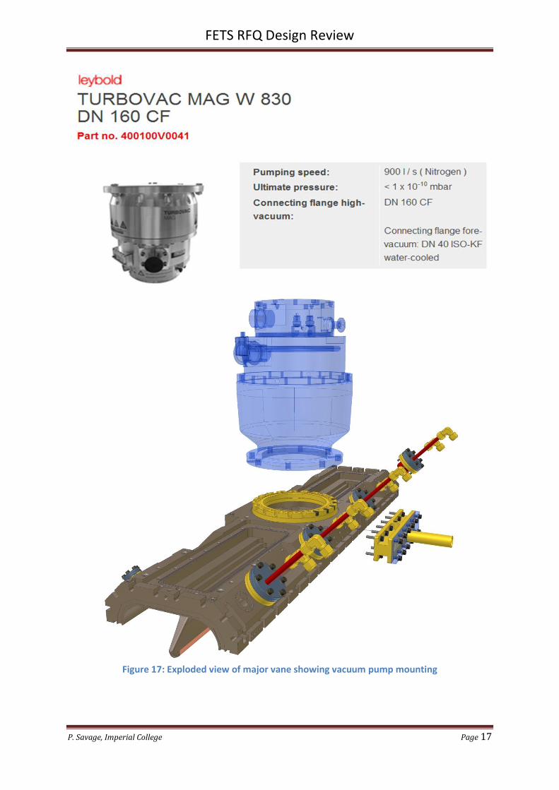
Probe Port
Name: Probe Port
Function: Provide CF16 port for vacuum measurement and/or analysis
Quantity: 4 per major vane
Table 3: CF flange dimensions, source Leybold 2005
Figure 23: Probe Port plug assembly
FETS RFQ Design Review
P. Savage, Imperial College Page 24
Figure 24: Probe Port location on RFQ major vane
Figure 25: Probe port modified CF16 bored flange
Flange: Modified Kurt Lesker CF flange F0133X000NM
Vacuum seal: Viton O ring 0181-16
Screws: M3 x 12 Stainless Steel Caphead

FETS RFQ Design Review
P. Savage, Imperial College Page 25
Figure 26: Probe port modified CF16 blank flange
Flange: Modified Kurt Lesker CF flange F0133X000N
Vacuum seal: Viton or copper standard CF gasket
Screws: M4 x 12 Stainless Steel Caphead

FETS RFQ Design Review
P. Savage, Imperial College Page 26
Tuners
The tuners are simple cylinders that fit into ports that are equi-spaced transversally in the RFQ.
There are 8 tuner ports per major vane giving a total of 16 tuner ports per 1m length of RFQ. Each
tuner will be water cooled and mounts to the RFQ via a stainless steel interim flange. This will
protect the copper threads from stripping.
Figure 27: Tuner port location on RFQ major vane
The RFQ frequency has been modelled to be correct when the tuner faces are sitting flush with the
inner surface of the quadrant radius. Once the RFQ has been assembled a bead pull test will
determine whether the longitudinal fields are sufficiently flat. If required the tuners will be skimmed
to make them protrude less, increasing the internal volume and driving the frequency down.
Alternatively the interim flange will be skimmed making the tuner protrude into the cavity, reducing
the internal volume and driving the frequency up.
Figure 28: Section view of static tuner

FETS RFQ Design Review
P. Savage, Imperial College Page 27
In addition one tuner port per 1m RFQ section will be fitted with a moveable tuner. The aim of the
moveable tuner is to constantly move into and out of the RFQ in response to a signal from the
feedback system. A loop protruding inside the RFQ will send a signal to the feedback system. The
frequency will change due to volume changes caused by fluctuations in temperature. The movement
is provided by a ZLTM50M (stepper motor) linear shift mechanism from VG Scienta.
Figure 29: ZLTM50M linear shift from VG Scienta

FETS RFQ Design Review
P. Savage, Imperial College Page 28
Figure 30: Linear Transfer Mechanisms by VG Scienta

FETS RFQ Design Review
P. Savage, Imperial College Page 29
Finger Strip RF Seal
LONGITUDINAL AND TRANSVERSE JOINTS
Groove depth: 25% to 50% compression.
Thickness = 2.79mm ~ 2.80mm
25% of 2.80mm = 0.70mm. Therefore groove depth = 2.10mm.
50% of 2.80mm = 1.40mm. Therefore groove depth = 1.40mm.
37.5% depth longitudinal (Groove on one side only) = 1.75mm +/- 0.2mm
37.5% depth transverse (Groove on both sides) = 0.88mm +/- 0.1mm
Load at 37.5% compression = 76 kg/m
Groove width: 8.00mm +/- 0.1mm
Supplier: TBA Electro Conductive Products Ltd.
Quantity: 6m per 1m RFQ assembly
Order quantity = 30m

FETS RFQ Design Review
P. Savage, Imperial College Page 30
TUNER AND PROBE PORTS
Groove depth: 25% to 50% compression.
Thickness = 2.79mm ~ 2.80mm
25% of 2.80mm = 0.70mm. Therefore groove depth = 2.10mm.
50% of 2.80mm = 1.40mm. Therefore groove depth = 1.40mm.
37.5% depth (Groove on one side only) = 1.75mm +/- 0.2mm
Load at 37.5% compression = 19 kg/m
Groove width: 6.60mm +/- 0.1mm
Supplier: TBA Electro Conductive Products Ltd.
Quantity: 3m per 1m RFQ assembly
Order quantity = 15m
How much current will the finger strip need to withstand? “Assuming 500 kW of RF power in the copper I get an rms current averaged over the structure of 10.4 kA based on the surface resistance. However this current flows through all the four fingerstrip joints simultaneously giving 26 A/cm rms peak for a 4m RFQ or 2.6 A/cm rms averaged for the duty factor.” – Alan, 27th Sep 2011

FETS RFQ Design Review
P. Savage, Imperial College Page 31
Cooling Pockets The RF power fed into the RFQ will make it hot. If it gets hot it will grow and go off-tune. We therefore need to maintain a stable temperature and this will be achieved with cooling water circuits. Conventionally RFQs have gun drilled channels running the full length that are blanked off at the end faces using vacuum brazed copper plugs. Access to the drilled holes is via holes drilled into the outer faces. Our design philosophy of avoiding vacuum brazing meant that this option would have required a novel end face plug seal. In addition, to avoid having a water seal inside the vacuum and to avoid the problems caused by deep drilling holes in copper we opted to mill channels into the RFQ from the outer faces. The advantages of this concept include:
1. No water seal inside the vacuum 2. No need to consider drift from long gun drilled holes 3. Accessible for cleaning 4. The coolant run can be modified by modifying the baffles.
The disadvantages of this concept include:
1. Large volume of material needs to be removed to get close to the vane tip 2. Getting coolant close to the vane cutback is challenging
Figure 31: Major vane cooling pockets

FETS RFQ Design Review
P. Savage, Imperial College Page 32
Figure 32: Section view showing major vane fitted with cooling baffles

FETS RFQ Design Review
P. Savage, Imperial College Page 33
Figure 33: Coolant path around baffles in major vane
Figure 34: Minor vane cooling channel lids – baffles not shown

FETS RFQ Design Review
P. Savage, Imperial College Page 34
Support System
Figure 35: RFQ 1m section support system
Each (nominally) 1m long RFQ section is mounted into a cradle which in turn mounts to a support
frame via a kinematic system. The entire support system can be moved in Z along the FETS rail
system.
The centre of the FETS rail system is at 800mm above the hall floor. The FETS beam axis is 800mm
above the rail system centre (the plane that passes through the axes of both rails).
Figure 36: Four RFQ support frames on the FETS

FETS RFQ Design Review
P. Savage, Imperial College Page 35
RFQ Alignment
The procedure for aligning each RFQ section relative to the beam axis will be discussed and
approved by the RAL alignment team.
The main alignment steps can be envisaged as:
1. Levelling
2. Setting the height
3. Setting the transverse alignment
Levelling:
Adjust the three screw jacks until the datum pads that create datum face A on a major vane are level
to within 50 microns. This will ensure that the vanes have a rotation of less than 0,0110 - see figure
n. Each screw jack uses a standard M20 x 2,5 thread which provides 50 microns translation for a 7.20
turn.
Figure 37: RFQ transverse rotation
Setting the height:
Rotate the three screw jacks by the same amount to achieve the desired height. If required dowel
holes on the end faces of the RFQ can be used as a reference to the position of the vane tips.
Setting the transverse alignment:
Undo the bolts on the base of the kinematic system and use the jacking screws to position the frame
transversally. Longitudinal positioning will be made when the RFQ sections are bolted together.

FETS RFQ Design Review
P. Savage, Imperial College Page 36
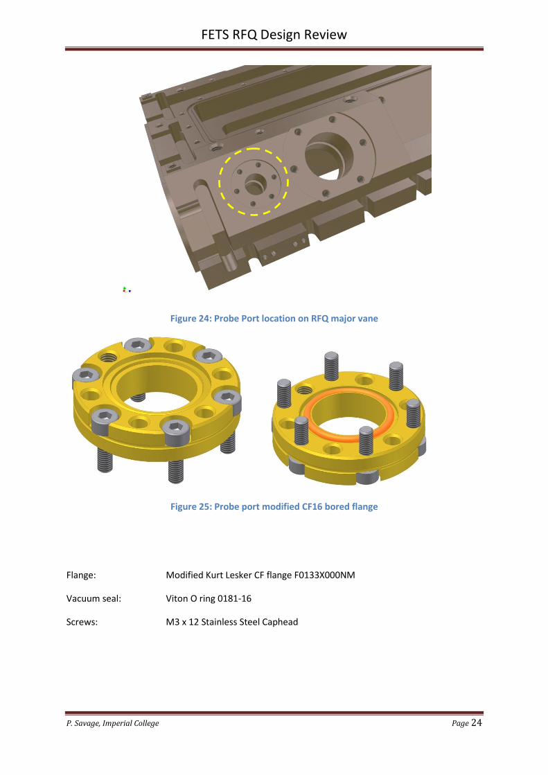
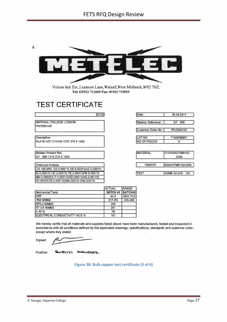
Bulk Copper
Table 4: Copper prices and weights
Contact: Bob Richards
FETS RFQ Design Review
P. Savage, Imperial College Page 37
Figure 38: Bulk copper test certificate (3 of 4)

FETS RFQ Design Review
P. Savage, Imperial College Page 38
Low Energy End
Figure 39: RFQ Low energy end profile
Figure 40: LEBT to RFQ interface

FETS RFQ Design Review
P. Savage, Imperial College Page 39
High Energy End
Figure 41: RFQ High energy end profile

FETS RFQ Design Review
P. Savage, Imperial College Page 40
Modulation Compensation
Any internal features that change the internal volume will alter the frequency. The last features to
be modelled were the vane modulations. The effect of the vane modulations on frequency can be
seen in figure 42.
Figure 42: RFQ frequency versus quadrant radii - Scott Lawrie, RAL
One idea to offset the changing frequency with length was to have different quadrant radii for
different RFQ sections. However this would present too many engineering challenges with custom
designs required for each section and mating problems at the section to section interfaces.
The chosen concept was to maintain constant quadrant radius along the entire 4m RFQ length and
introduce grooves where required to alter the internal volume, see figure 43.

FETS RFQ Design Review
P. Savage, Imperial College Page 41
Figure 43: Diameter 25mm ball nosed cutter used to create modulation compensation grooves
Scott’s ANSYS modelling showed that a constant frequency over the 4m RFQ length can be achieved
with the following groove specification:
Section Portion Groove depth
1 All None
2 First 0,5m None
2 Last 0,5m 2,55 mm
3 All 4,10 mm
4 All 4,10 mm
Table 5: Groove depths required in RFQ sections
For more information refer to “RFQ Eigenmode Overview” by Scott Lawrie

FETS RFQ Design Review
P. Savage, Imperial College Page 42
Inspection
Figure 44: Inspecting the major vane internal profile and interface surfaces.
Inspection to take place and approved before delivery to the customer.
Measurements (w.r.t. datum dowel holes) to prove part is within tolerance for:
1. Internal profile at discrete intervals along the length.
2. Interface surfaces (datum D)
3. End faces
Visual inspection of external features.

FETS RFQ Design Review
P. Savage, Imperial College Page 43
Figure 45: Inspecting the minor vane internal profile and interface surfaces.