FERROUS SCRAP PREHEATING SYSTEM PHASE 111 FINAL...
30
Surface"Combustion FERROUS SCRAP PREHEATING SYSTEM PHASE 111 = FINAL REPORT Work Performed Under Contract No. DE-AC02-89CE40874 Prepared For: U.S. Department of Energy Washington, D.C. Prepared By: Surface Combustion, Inc. Maumee, Ohio 43537 Surface Contract Number RX-6127 May 13,1996 DISTRIBUTION OF THIS DOCUMENT IS UNLIMITED
Transcript of FERROUS SCRAP PREHEATING SYSTEM PHASE 111 FINAL...

Surface" Combustion
FERROUS SCRAP PREHEATING SYSTEM
PHASE 111 = FINAL REPORT
Work Performed Under Contract No. DE-AC02-89CE40874
Prepared For:
U.S. Department of Energy Washington, D.C.
Prepared By:
Surface Combustion, Inc. Maumee, Ohio 43537
Surface Contract Number RX-6127
May 13,1996
DISTRIBUTION OF THIS DOCUMENT IS UNLIMITED

Surface Combustion Q TABLE OF CONTENTS
ABSTRACT ..................................................................................................................... ii ... EXECUTIVE SUMMARY ................................................................................................. 111
1.0 OBJECTIVE .............................................................................................................I
2.0 INTRODUCTION ...................................................................................................... 2 2.1 Background ........................................................................................................ 3
3.0 PREHEATING FURNACE DESCRIPTION .............................................................. 5
4.0 DESCRIPTION OF THE WORK AND RESULTS .................................................. 10 4.1 Purchase Components .................................................................................... 10 4.2 Fabricate System ............................................................................................. 10 4.3 Installation ........................................................................................................ 11 4.4 Start-up And Preliminary Testing .................................................................... 12 4.5 Performance Testing ...................................................... ,. ................................ 12 4.6 Production Data Collection ........................................................ : ..................... 13 4.7 Environmental Activities ................................................................................... 13 4.8 Data Analysis And ReporVAdministration ........................................................ 14
5.0 ANALYSIS. CONCLUSIONS AND RECOMMENDATIONS ................................... 15 5.1 Economic Analysis ........................................................................................... 15 5.2 Emissions ........................................................................................................ 20 5.3 Evaluation Of Applicability Of Technology ....................................................... 21 5.4 Recommendations ........................................................................................... 22
FIGURES Figure 1 . Ferrous Scrap Preheating System ................................................................ 6 Figure 2 - Preheater Chamber and Car ......................................................................... 7 Figure 3 - Furnace Preheater Operation ........................................................................ 9
TABLES Table 1 . Scrap Preheater Economics ........................................................................... 16 Table 2 . Scrap Preheater Economics ........................................................................... 17 Table 3 . Scrap Preheater Economics ........................................................................... 18 Table 4 . Scrap Preheater Economics ........................................................................... 19 Table 5 . Projected Emissions For Stainless Steel Preheater ....................................... 20 Table 6 . Waste Reduction For Combined Arc Furnace and Preheater ........................ 21
May 13. 1996 i RX-6127

DISCLAIMER
Portions of this document may be illegible in electronic image products. Images are produced from the best available original document.
. .

Surface Cornbustlon 8 ABSTRACT
Utilizing electric arc melters for making steel has allowed many smaller manufacturers to compete with large integrated mills. The electric arc furnace melts scrap to produce steel. The subject of this report is a Scrap Preheater that heats and cleans the arc furnace scrap using its own low cost natural gas energy supply. Scrap preheating can increase the capacity of a given arc furnace and reduce the operating costs. In addition it reduces the air emissions and allows utilization of lower cost scrap.
The program was divided into three phases and was to culminate with an operating prototype at a demonstration host site steel mill. A host site agreement was executed and critical components were tested. The prototype scrap preheater was completely designed. It was sized to preheat 30 tons of scrap in a scrap bucket in 30 minutes. Energy is supplied by a rich fume reactor that completely oxidizes organics from the scrap and auxiliary natural gas. There were several delays and changes in the project that resulted in the host site requesting to withdraw from the program. Extensive efforts were made to secure a replacement host site. However, when another host could not be found, the project was terminated.
DISCLAIMER
This report was prepared as an account of work sponsored by an agency of the United States Government. Neither the United States Government nor any agency thereof, nor any of their employees, makes any warranty, express or implied, or assumes any legal liability or responsi- bility for the accuracy, completeness, or usefulness of any information, apparatus, product, or process disclosed, or represents that its use would not infringe privately owned rights. Refer- ence herein to any specific commercial product, process, or service by trade name, trademark, manufacturer, or otherwise does not necessarily constitute or imply its endorsement, recorn- mendation, or favoring by the United States Government or any agency thereof. The views and opinions of authors expressed herein do not necessarily state or reflect those of the United States Government or any agency thereof.
May 13,1996 ii RX-6127

Surface Combustion Q EXECUTIVE SUMMARY
Utilization of electric arc steel making has allowed many smaller producers to compete with the large mills. An electric arc furnace (EAF) melts scrap metal to produce a variety of steel products. Using scrap as the metal source is less costly than refining from ores, but the metal is of a lower quality due to impurities in the scrap. Over the years, methods have been developed to improve EAF metal quality and reduce the cost of production. As a result, an increasing share of total steel production is shifting to EAFs. By recent estimates, EAF production is growing at a rate of about 10% per year, and currently accounts for nearly one half of all U.S. steel production (U.S. Department of Energy and Electric Power Research Institute Project 2787-2, 1987) .
The subject of this report is a Scrap Preheating System, a new method of preheating scrap metal before it is charged into an EAF. A major benefit in the U.S. is the partial substitution of gas for electricity. In the scrap preheating system, a portion of the energy is supplied in a separate vessel, causing the EAF to use less energy, which shortens the heating time. The general effect is that the arc furnace can produce more steel in a given time at a reduced cost per ton of molten metal. Scrap preheating is practiced in Europe and Asia, but in the U.S., the energy cost structure and other physical limitations have deterred its acceptance.
The scrap preheating system is a stand-alone furnace with its own gas fueled energy source. The preheater operates under controlled conditions, specifically, a low oxygen level atmosphere in which oils and other organics in the scrap contribute to the energy of preheat. The scrap is heated in the same buckets that are normally used to transport the scrap from the yard to the melter. The unit can be installed in a remote location, possibly in the scrap yard.
Surface Combustion estimates that the proposed Scrap Preheating Furnace can reduce the cost of melting steel by $11 per ton. The savings are in reduced energy cost, increased productivity and yield, reduced electrode and refractory usage, and the ability to process a lower grade of oily scrap. Typically, these systems will heat a thirty ton bucket of scrap in about thirty minutes. Most of these units will have a one or two year payback period.
Preheated scrap requires less time in the electric arc furnace, thus reducing the quantity of ozone related gases emitted per ton of steel produced. Specifically the preheating furnace generates less NOx and volatile organic compounds (VOC) than an electric arc furnace. In addition, it may be possible to melt some of the oily in-plant metallic wastes, and avoid disposal costs.
May 13,1996 iii RX-6127

Surface Combustlon 8 The program is divided into three phases. Phase 12, Marketing and Technology Evaluation, is reported in the Phase I Final Report dated June, 1990. Phase 113, critical item testing and system design is reported in Phase II Final Report dated November 23, 1993. Phase 111 was to culminate in a full sized demonstration furnace installed and operated at Washington Steel Corporation's Melt Shop in Houston, Pennsylvania. This program is sponsored by the U.S. Department of Energy (Office of Industrial Technologies) with major co-funding by a consortium of natural gas companies through the Industrial Gas Technology Commercialization Center (a Consortium of Natural Gas Suppliers), Washington Steel Corporation (the Host Site) and Surface Combustion, Inc. (prime contractor and equipment supplier)2.
At the start of Phase Ill, commercial components were placed on order and detailed installation plans were prepared by the host site Washington Steel. However, Washington Steel was purchased by Lukens, and subsequently made a series of melt shop improvements increasing their melting capacity. As a result, the preheater design capacity was too small. In addition, the unit needed to be installed in a different location resulting in considerably higher costs than the original estimates. All parties mutually agreed to terminate the agreement with Washington Steel and search for a new host demonstration site. The search was narrowed to three (3) mills that could use the system with minimal change to the original design and size. After further negotiations none of these sites were willing to host a demonstration. The project has therefore been terminated for lack of a host site.
Surface Combustion still feels that the Scrap Preheater is a technically sound approach. In addition, the United States steel industry is showing more interest in preheating and is considering installation of systems. The economics of using this preheater shows a one to two year payback. The project should be re-evaluated in three to five years, with special emphasis on reducing installed cost.
May 13,1996 iv RX-6127

Surface Cornbustlon Q 1 .O OBJECTIVE
The overall objective of this program was to demonstrate the benefits of preheating scrap for the production of steel using an electric arc furnace. A full sized prototype preheater was to be used in a host mini-mill. The program was divided into three phases each with the following objectives:
Phase I: Evaluate the preheating concept, survey the potential users and determine the applicability of the approach, and complete an agreement with a demonstration host site.
Phase I I : Test the critical components, interface with the host site and prepare detail design for the system, and order long lead time items.
Phase I l l : Fabricate and install the system, test the system, and determine the operating economics.
The reports for Phases I and I I have been issued.
May 13,1996 1 RX-6127
Surface Combustion 8 2.0 INTRODUCTION
The U.S. steel industry has recovered from its slump in the early 1980's and is again becoming more internationally competitive. Changes in economics and technology have resulted in a smaller number of more efficient mills that have begun to make the capital investment and improvements needed to make the U.S. a world leader in steel production. One of the fastest growing sectors of steel production is the recycling of scrap steel using an Electric Arc Furnace (EAF)4. Melting scrap allows production of molten metal at a lower cost than is possible by refining iron ore in a blast furnace. Although the quality of metal from an arc furnace is lower, on-going improvements in quality have made the product competitive in an expanding sector of the total steel market.
The subject of this report is a thermal system which preheats scrap steel before charging into an EAF. The preheater is designed to improve overall productivity and efficiency of the melting operation. The scrap metal is loaded int0.a handling bucket and then transported to the preheat chamber. Thermal energy is applied to the scrap, removing moisture and oils while bringing the metal to a suitable preheat temperature for the EAF. After processing, the heated scrap is transported to the EAF. The EAF creates very high temperatures with electric arcs, creating a molten metal pool covered
' with slag impurities. The molten steel is then transferred to a refining vessel which adjusts the steel composition prior to forming or continuous casting: The solidified metal is rolled and milled into forms that are used to make products.
Preheating scrap for an EAF is not a new idea. It is currently practiced in various forms in Europe and Asia, but the foreign technology has not been economically attractive for the U.S. steel industry. The preheating approach presented in this report is a result of examining domestic needs, and designing a preheater that is specifically aimed at U.S. physical retrofit requirements and the domestic energy cost structure. A survey of EAF operators revealed considerable interest in this approach, but also a level of reluctance in investing in a system5.
The overall objective of this project is to build and demonstrate a full scale scrap preheater that can be used to verify economic projections and serve as a model for future installations. The general project is divided into three phases, including system evaluation at the Host Site. Previous reports covered Phase 12, the technical and market feasibility activities and Phase I 13, testing of critical components and detailed design of the system. This report covers Phase Ill which was planned to fabricate, install, and test a demonstration preheater. The project, sponsored by the U.S. Department of Energy Office of Industrial Technologies, has substantial cost sharing by The Industrial Gas Technology Commercialization Center (a Consortium of Natural Gas S u p p I i e r s) .
May 13,1996 2 RX-6127

Surface Combustion 8 2.1 BACKGROUND
The arrival of EAF technology led to the formation of steel mini-mills and many smaller steel suppliers. From the beginning, there has been continuous improvement in the efficiency of arc furnace operations. Some of these innovations are water-cooled panels, oxy-fuel burners, foamy slag practices, and use of direct reduced iron ore6 as feed stock. In addition, the power supplied to a given furnace has been increasing. These changes have reduced the time it takes to melt several charges of scrap from about three hours to about one hour, thereby increasing the productivity of the furnace. A' DOE and EPRI publication entitled Technoeconomic Assessment of Electric Steel Making Through the Year 2000, illustrates the trends in EAF operations, and lists scrap preheating as the next logical improvement'.
In the early 1 9 8 0 ' ~ ~ Surface Combustion, under contract with Columbia Gas System Service Corporation and Southern California Gas Co., began the development that led to the current Ferrous Scrap Preheater approach. A pilot plant was built that heated 6 ton batches of scrap in a chamber while measuring the temperature and heating rate. One parameter being tested was the effect of the recirculating gas flow rate.
As predicted by a heat transfer model, the rate of thermal transfer is directly proportional to the gas recirculation rate7. During the heating process, hot gases enter the top of the load and lose energy as they pass downward. As a result, the top of the load starts heating first as a thermal front passes down through the load. A cycle is complete when the thermal front reaches the bottom of the load. It was found that a llOO°F inlet gas temperature resulted in an average metal temperature of 900 to 1000°F. If the total thermal energy in the scrap was evenly distributed, all of the scrap would be at the average temperature. Since there are temperature gradients in the scrap, some areas will be above the average temperature while others will be lower. Two charges of preheated scrap were melted in an EAF at National Castings in Toledo, Ohio. In both cases melting times were decreased. The results proved that a preheater of this type was technically possible.
Surface Combustion enhanced the approach for preheating by incorporating feedback from EAF operators. A marketing effort in the mid 1980's resulted in several good potential demonstration sites, but the economics at that time were not favorable. Most of the steel mills were experiencing financial difficulties and were unwilling to make major capital investments. These mills had excess melting capacity, and there was uncertainty about natural gas prices. The project was shelved because of industry conditions. With the recovery of the U.S. steel industry, it was time to re-evaluate this method of enhancing steel production.
May 13,1996 3 RX-6127

Surface Combustion Q In Phase I it was determined, 1) that scrap preheating is technically and mechanically suited for enhancing steel and stainless steel production, and 2) a need exists- for a scrap preheating system that can reduce the cost of producing steel.
Although preheating is used routinely in Europe and Asia, it has not been accepted as well in the United States. One of the first North American attempts at scrap preheating was installed at Timken, Fairfield, Ohio. It utilized Japanese "fourth hole" technology where the exhaust gas from the arc furnace is used as the energy source to the preheat scrap. This system is no longer in service mainly due to difficulty in coordinating the preheater to arc furnace operating schedule. The Consteel process employs continuous preheating and melting. It has been applied to three sites in the United States, but is best suited for new mills rather than retrofit to existing melters'. The Fuchs preheater employs a shaft furnace attached to top of an arc furnace. They have successful installations in England and Mexico and have plans for United States sitesg. In this approach, the first charge is placed in the furnace and the second charge is preheated in the shaft. The first charge is not preheated. Other. alternatives to preheating include increasing the power to the melter, use of oxy-fuel burners, and using two shells, one to preheat while the electrodes are in the other one melting the charge".
A detailed air emission study was completed as part of Phase I of the project. It included measurements of potential emissions from the metal and the organics that may be present on the scrap. Measurements included emission of heavy metal and dioxins.
We feel that the proposed preheater system is superior to the current alternatives because it is easier to retrofit, it reduces emissions, it can utilize lower grade oily scrap, preheats the entire charge, and does not increase electrical demand. The independent energy supply allows total preheat of all of the scrap and does not require refractory lined scrap buckets. The ideal application is one in which there is a need for increased capacity, oily scrap can be utilized, and there is a large premium for increased electrical demand.
May 13,1996 4 RX-6127

Surface Combustion 8 3.0 PREHEATING FURNACE DESCRIPTION
The preheating furnace consists of three major components: 1) the I ieating chamber, 2) the recirculating fan, and 3) the Rich Fume Reactor (RFR). (The components are shown in Figure 1.) The buckets of scrap are placed in the heating chamber and sealed. Hot gases are then forced through the bucket by the recirculating fan. The gases pass through the bucket and exit through the bottom. After exiting the bucket, the gases pass to the RFR where natural gas and organics from the scrap are burned to reheat the gas stream. Finally, the gas exits the RFR and is passed through the recirculating fan back to the top of the bucket. A portion of the stream is vented downstream of the RFR. The system pressure is maintained using an exhaust fan in this vent stream.
The scrap buckets are transferred into and out of the heating chamber using transfer cars. There are two cars, each containing the lower portion of a heating chamber. A bucket is placed on the car within the lower heating chamber section and the car moves into position. The top of the heating chamber is lowered over the bucket sealing onto the lower heating chamber on the car. The hood seal is lowered to the top of the scrap bucket and the heating cycle begins. When the cycle is complete, the heating chamber cover is raised and transfer car moves to the pick-up position while the other car moves the next load plus the heating position.
The heating chamber is round and contains insulation on its interior. There are two ducts attached to the top of the chamber, one to admit the hot gases and the other to duct the return gases. When the cover is raised, the ducts also lift. When the cover is lowered, the moving ducts connect to the stationary ducts using water seals. Figure 2 is a detail of the heating chamber containing a bucket. The removable cover is the portion above the chamber split line. The portion below the split line is the lower heating chamber which is attached to the transfer car. The bucket sits in a positioning cradle which is also attached to the car. The hot gas enters through the top of the chamber and into the hood. The hood seals to the top of the bucket using a ceramic fiber material. There is an expansion joint at the top of the hood to compensate for any misalignment with the bucket or thermal expansion.
The RFR is capable of operating at 1400°F to 1600°F and completely burning natural gas and organics with a resulting flue gas having less than 2% oxygen. Two natural gas burners fire tangentially at the upstream end of the RFR providing stable combustion. Auxiliary natural gas is added to the flue gas stream of these burners. The recycling gases enter the RFR axially through a duct that is surrounded by the combustion air inlet. This mixing arrangement makes the RFR capable of operating over a wide range of conditions. Down-stream of the mixing area, a residence chamber completes the combustion reaction. The flows of combustion air and auxiliary fuel vary to control the oxygen level and the temperature of the RFR exhaust as process needs change. Cutting oils, water, and other organics, driven-off the scrap as it is heated, will pass to the RFR and are thermally oxidized.
-
May 13,1996 5 RX-6127

Surface Combustion Q FIGURE 1
Scrap Preheating Furnace
NOTE: BY-PASS DUCTING REMOVED FOR CLARm.
May 13,1996 6 RX-6127

Surface Combustion 8 FIGURE 2
Preheater Chamber and Car
PWEAT C W
'CHAMBER SPLIT LINE
May 13,1996 7 RX-6127

Surface Combustlon 8 The anticipated temperature of the gas entering the preheating chamber is 1 100°F. A portion of the recycle stream will by-pass the RFR which operates at 1400°F to 1 6OO0F, and mix with the RFR off-gases to maintain the 11 00°F gas-preheat temperature. The mixture temperature is controlled by varying the fraction of the gas that by-passes the RFR. The mixed gases pass through the recirculating blower and then to the heating chamber.
The heating chamber is a round chamber that is raised and lowered with its own lift mechanism. The chamber has a hood.which is supported from the inside roof of the pieheat chamber. The hood is connected to the inlet duct of the preheater chamber through a high temperature expansion joint. The hood rests on top of the scrap bucket and is sealed with a seal which was selected from Phase II testing.
The ductwork connecting the preheating chamber, the RFR and the recirculation fan is designed with isolation valves and bypass lines to isolate the preheater chamber when scrap buckets are being charged or discharged. This bypass ductwork is used to maintain RFR operations during bucket changes.
There are control valves and a bypass line around the RFR to temper the gases flowing into the scrap bucket. The ducts are internally insulated and have high temperature expansion joints.
The scrap preheating furnace is controlled using three temperature control loops, an oxygen control loop, and a pressure control loop. The temperature loops control the gases entering the heating chamber, the RFR auxiliary fuel flow, and the cold air infiltration at the exhaust fan. The oxygen controller maintains the oxygen level in the exhaust from the RFR, and the pressure controller maintains the draft level in the heating chamber.
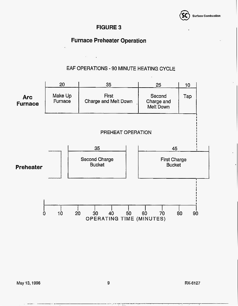
The operation of the preheater can be coordinated with the arc furnace to allow preheating of multiple scrap charges. Figure 3 shows how this is accomplished for a typical arc furnace with 90 minute tap to tap time and two charges. The first charge is the larger and takes 45 minutes to preheat. It is started during the melt down of the second charge and continues to preheat during tapping and furnace make-up. Note if the arc furnace energy were used as the energy source, much less preheat time is available since there is no heat in the arc furnace during tapping and furnace make-up. The second charge, which is smaller, is preheated while the first charge is being melted down. The combination of longer available preheating time and independent control of the energy provides complete preheat of the entire charge.
May 13,1996 8 RX-6127
Surface Combustion Q
20
FIGURE 3
35 25 I 10 I
Furnace Preheater Operation
EAF OPERATIONS - 90 MINUTE HEATING CYCLE
Make Up Furnace
Arc Furnace
First Charge and Melt Down
Preheater
May 13,1996
Second Charge and Melt Down
PREHEAT OPERATION
35 .................
Second Charge Bucket 1 1 1
....... - ..... ....
I I I I I I I I I I I I 45 I
First Charge Bucket
1 - I I I I I I I I I
I 0 10 20 30 40 50 60 70 80 90
OPERATING TIME (MINUTES)
9 RX-6127

Surface Combustion Q 4.0 DESCRIPTION OF THE WORK AND RESULTS
Early in Phase 111 the Washington Steel host site agreement was terminated and most of the work was stopped. There was a period when we attempted to find a new host site and secure additional funding. When this failed, the program was terminated. The following is a definition of each task and the status of its execution when the program was terminated.
Phase I l l test plan was divided into the following tasks. The tasks are presented as they were stated in the test plan. The status represents that at the end of the project.
4.1 PURCHASE COMPONENTS
All of the required commercial components needed for the assembly and testing of the system will be purchased in this task. Purchasing will be handled through the Maumee office. Good commercial practice of multiple bids will be used. Savings realized due to the buying power of Surface will be applied to this task. The commercial items will include control systems, fans and motors, refractory, electrical components, burners, etc. Since most of these items will be shipped directly to the fabricator(s), quality assurance will be per the fabricator's QNQC plan.
4.1.1 Status
Approximately 95% of all of the commercial items were placed on order. When the host site agreement with Washington Steel was terminated, un-shipped purchase orders were placed on hold. When the program was terminated, standard commercial items were returned to vendors. Special items such as transfer cars lift mechanisms were accepted and disposed.
4.2 FABRICATE SYSTEM
The system will be shop fabricated and where possible, pre-piped, pre-wired and bricked. Purchase orders will be'awarded to one or more fabrication shops that will build components from the drawings supplied by Surface. Only experience proven shops that are capable of consistently high quality workmanship will be considered. Quality assurance procedures will be reviewed as pan' of the bid evaluation. The fabricator will supply steel and miscellaneous construction material as part of their scope. Commercial items will be shipped to the proper fabricator who will install them in the system. During the fabrication Surface Combustion will have an inspector responsible for assuring that the work meets the Surface Combustion quality assurance standards.
May 13,1996 10 RX-6127
@ Surface Combustion
Fabricated components will be moved to one location where the major subsystems will be assembled and given a final checkout using an approved shop test plan. At this time major joints will be made and the system will be aligned. Moving parts will be tested and cycled where possible. Instrumentation, including controllers and relays, will be assembled into the appropriate electrical cabinets and prewired to terminal strips. The systems will be equipped with transmitters to determine the operating cost and performance. There will be a communication link to the data acquisition computer purchased as part of Phase II.
All combustion safety systems will conform to the National Fire Prevention Association guidelines. All components will be of the heavy duty quality required for steel mill service.
4.2.1 Status
The prewired control cabinet was completed, but the major fabrication purchase orders were not released. Based upon expenditures, this task was about 2% complete.
4.3 INSTALLATION
Early in this phase site preparation will begin with the removal of obstructing equipment and preparation of a concrete foundation for the equipment. The work will be done by local subcontractor(s) under the direction of Surface Combustion. All utilities will be brought to immediate area. The pre-tested subassemblies will be shipped to the site and reassembled. Interconnecting piping and wiring will be completed and the entire system will be checked for concurrence to the drawings and bills of material.
The burners will be lit, control valves set, transmitters calibrated, and the refractory dried and cured. Components will be leak tested. A pre-start up test plan will be prepared and executed. The installation will be examined to assure compliance with the host site and Surface Combustion QNQC procedures.
’ This task also includes the testing and data collection to establish a baseline operating point without preheating. The baseline will be used to calculate the operating improvements with preheat. The EAF will be operated for a period that is statistically significant collecting operating and cost data for the calculations. The calculations and acceptance criteria will be agreed to by Surface and the host site before they are released.
We plan to install the unit at the Washington Steel melt shop located in Houston, PA. The shop is equipped with a new 60 ton EAF with an AOD upstream of a continuous caster. They specialize in stainless steel products. Scrap is purchased from a dealer in Carnegie, PA and shipped in daily in bulk containers.
May 13,1996 11 RX-6127
I .. . , . --- - ____I-_ I__

Surface Combustion 8 4.3.1 Status
The initial porti n of this tasks was interface with the host site to prepare an installation plan and definitize estimate of installation costs. This portion was completed with Washington Steel prior to their termination. The actual installation of the system was not started.
4.4 START-UP AND PRELIMINARY TESTING
The unit will be operated as a system with all components functioning. Buckets will be placed in the heating chamber and the flow rates measured. The rich fume reactor will be started up and the proper control parameters entered into the controllers. A load of scrap will be heated to confirm system operation. During this time it will probably be necessary to make minor adjustments to the equipment to establish smooth operation.
4.4.1 Status
Start-up and preliminary test plans were prepared. No actual start-up or testing was done in this phase.
4.5 PERFORMANCE TESTING
The data collected during this phase will be used to establish the operating parameters of the system and the savings that can be achieved by using it. Each of the savings areas will be evaluated using the statistical approach established in Task 3.3. A "standard" load will be established and heated in a way that heating rate data can be collected. The initial testing will involve the preheater, but in later tests the loads will be charged into the EAF to complete the analysis. The data collected during these tests will be stored in the data acquisition computer. Data analysis will be done jointly by the host site and Surface. During the testing period, the host site operators will be trained in all aspects of the system operation.
It is probable that there will be some modifications required to achieve the desired operating conditions. These will be done as part of the project.
4.5.1 Status
Nothing was done for this task.
May 13,1996 12 RX-6127

Surface Combustion 8 4.6 PRODUCTION DATA COLLECTION
The real operating tests will come when the host site takes over control of the system. For a period of two (2) months the system will be operated by the host site under the guidance of Surface. The operating data will continue to be collected and integrated into the overall economical analysis. The items to be considered in the savings calculations are as follows:
Electricity Usage (Kwh/ton of metal) Electrical Demand Changes ($/Kw) Electrode Consumption (Ib. electrode/ton of metal) Preheater Operating Costs (utilities and operating labor) Savings from Lower Quality Scrap ($/ton of scrap) Increased Yield (ton of metal/ton of scrap) Refractory Consumption ($/ton of metal) Productivity Increase (tons of metal tapped per quarter)
At the conclusion of these tests, a complete economic analysis will be prepared jointly between the Host site and Surface. If the operation is successful and the savings are sufficient, the host site will be given the opportunity to continue to use the equipment.
4.6.1 Status
Nothing was done for this task.
4.7 ENVIRONMENTAL ACTIVITIES
It is anticipated that the system will be permitted as a piece of process equipment used in recycling steel. During the performance testing, exhaust gas analysis will be made that will document the expected emissions from the unit. This information will be used to gain the operating permits required.
Since there is a concern regarding the emissions of heavy metals from the preheater when heating galvanized stock, several loads of galvanized scrap will be heated while taking a detailed exhaust gas analysis. These loads will not be charged into the EAF since the host site is a producer of stainless steel.
Emissions from the EAF will be documented prior to preheater brought on line to establish a base line for this test.
4.7.1 Status
Assistance was given to Washington Steel to apply for a permit to install. The data was based upon the air emission study completed in Phase I and included expected VOC, NOx and particulate emissions.
May 13,1996 13 RX-6127
Surface Combustion 8 4.8 DATA ANALYSIS AND REPORT/ADMINISTRATION
The operating data from the testing tasks will be reduced and pres nt d in a series of memo reports. These will then be-compiled and augmented in preparation of the final report. At least two (2) presentations will be made documenting the test results and the economic advantages. Since this is a new product the market consultant who was part of Phase I1 will be retained to provide'customer needs and desires for the system.
Monthly reports, periodic reports, and project control will also be part of this task.
4.8.1 Status
In addition to the normal administrative activities, The following unanticipated activities were included in this activity: Termination of the Washington Steel host site agreement, mail and telephone search for new host site, and meetings with potential new host sites and preparation of additional background. data.
May 13,1996 14 RX-6127
_ _ , - _ _ .. I ___.-

Surface Combustion Q 5.0 ANALYSIS, CONCLUSIONS AND RECOMMENDATIONS
5.1 ECONOMIC ANALYSIS
Tables 1 through 4 list the cost savings and paybacks for four different cases of preheating. Two preheat temperatures are presented because of the uncertainty of the maximum allowable bucket temperature. The original assumption was that scrap could be preheated to 900°F using 11 00°F feed gas. This could result in a maximum bucket metal temperature of 1000°F. It may be necessary to limit the preheat temperature to 5OO0F if the maximum bucket temperature must be limited to 800°F. It is. unclear whether it will be possible to reinforce the buckets to achieve 900°F preheat or whether it will be necessary to change the alloy in the side of the bucket. Tables were prepared for both stainless steel and carbon steel. The difference between the two materials in the cost of the scrap, value of the product, and use of in plant oily fines as feed material for stainless steel. Use of these fines reduces the amount of scrap and eliminates the cost of disposal of the fines.
The capital and installation costs are taken from estimates prepared for purchase of these services. The utility and material costs are those for Washington Steel. Increased productivity values of preheater operations of 15% increase for 900°F and 7.5% increase for 500°F preheat are taken from published operating information. Savings from use of oily scrap were calculated assuming that it could be increased by 5% of the total charge and that the cost differential was that between turnings and high quality scrap (bales or bundles). This difference is about $50/ton for carbon steel and $1 OO/ton for stainless". The calculated paybacks of 1.5 to 2.1 years and IRR (Internal Rate of Return) of 65% to 42% are generally acceptable but mills may have potential investments with better paybacks. It is obvious that the major payback is from increase in productivity and use of oily scrap. Energy savings are too small to justify an investment of this size. Note that these paybacks assume that the mill can take advantage of all of the advantages of the preheating system.
May 13,1996 15 RX-6127

Surface Combustion 8 TABLE 1
* SCRAP PREHEATER ECONOMICS
Stainless Steel of 900°F Preheat
200,000 TonNear Capacity 9% Increase in Production at $40/Ton 5% Increase in Oily Scrap at $100/Ton
Capital Costs $1,900,000 Installation $600,000 Maintenance $57,000
Production Rate (TonNr) 200,000 Preheat Temperature (OF) 900 Savings 9.0%
Natural Gas (.267 Btu/Ton) $1 86,900 $3.50 per 1,000 CF Power Preheater (2.4 Kwh/Ton) $1 5,360 $0.032 per Kwh Electricity EAF (70 Kwh/Ton) ($448,000) $0.032 per Kwh Electrode Cost (.8 Lb/Ton) ($1 66,400) $1.04 per Lb Refractory Cost (9% Reduct) ($1 04,760) $5.82 per Ton
Oily Scrap (5% Increase) $1 00.00 per Ton of Scrap Increased Product (9.0%) $720,000 $40.00 per Ton
($1,000,000)
Depreciation 7 Year $357,143 Operating Savings ($1,719,160)
, Operating Cost $259,260 Net Income $1 ,I 02,757 Income Tax $551,379 After Tax Income $551,379 Non-Cash (Productivity) $720,000
I I I Total Annual Benefit I $1.628.521 I
Payback After Tax 1.54 Years After Tax 5 Year IRR 65.8%
May 13,1996 16 RX-6127

Surface Combustlon 8 TABLE 2
SCRAP PREHEATER ECONOMICS
Carbon Steel of 900°F Preheat
200,000 TonNear Capacity 9% Increase in Production at $40/Ton 5% increase in oily Scrap at $50/Ton
Capital Costs $1,900,000 Installation $600,000 Maintenance $57,000
I
Production Rate (TonNr) 200,000 Preheat Temperature ( O F ) 900 Savinas 9.0%
Natural Gas (.267 Btu/Ton) $1 86,900 $3.50 per 1,000 CF Power Preheater (2.4 Kwh/Ton) $1 5,360 $0.032 per Kwh Electricity EAF (70 Kwh/Ton) ($448,000) $0.032 per Kwh Electrode Cost (.8 Lb/Ton) ($1 66,400) $1.04 per Lb Refractory Cost (9% Reduct) ($1 04,760) $5.82 per Ton
__
Oily Scrap (5% Increase) ($500,000) $50.00 per Ton of Scrap Increased Product (9.0%) $720,000 $40.00 per Ton
Depreciation 7 Year $357,143 Operating Savings ($1,219,160) Operating Cost $259,260 Net Income $602,757 Income Tax $301,379 After Tax Income $301,379 Non-Cash (Productivity) $720,000
Total Annual Benefit $1,378,521
Payback After Tax 1.81 Years After Tax 5 Year IRR 52.9%
May 13,1996 17 RX-6127

Surface Comhustlon w TABLE 3
SCRAP PREHEATER ECONOMICS
Stainless Steel of 500°F Preheat
200,000 TonNear Capacity 7.5% Increase in Production at $40/Ton 5% Increase in Oily Scrap at $100/Ton
Capital Costs $1,900,000 Installation $600,000 Maintenance $45 , 0 00
Production Rate (TonNr) 200,000 Preheat TemDerature ( O F ) 500 ~ _ _
Savings 7.5% I 1 1 I
Depreciation 7 Year $357,143 ODeratina Savinas ($1.394.500) Operating Cost $95,740 Net Income $941.61 7 Income Tax $470,809 After Tax Income $470,809 Non-Cash (Productivity) $600,000
1 I 1 Total Annual Benefit I $1.427.951 I 1 Payback After Tax 1.75 Years After Tax 5 Year IRR 55.4%
May 13,1996 18 RX-6127
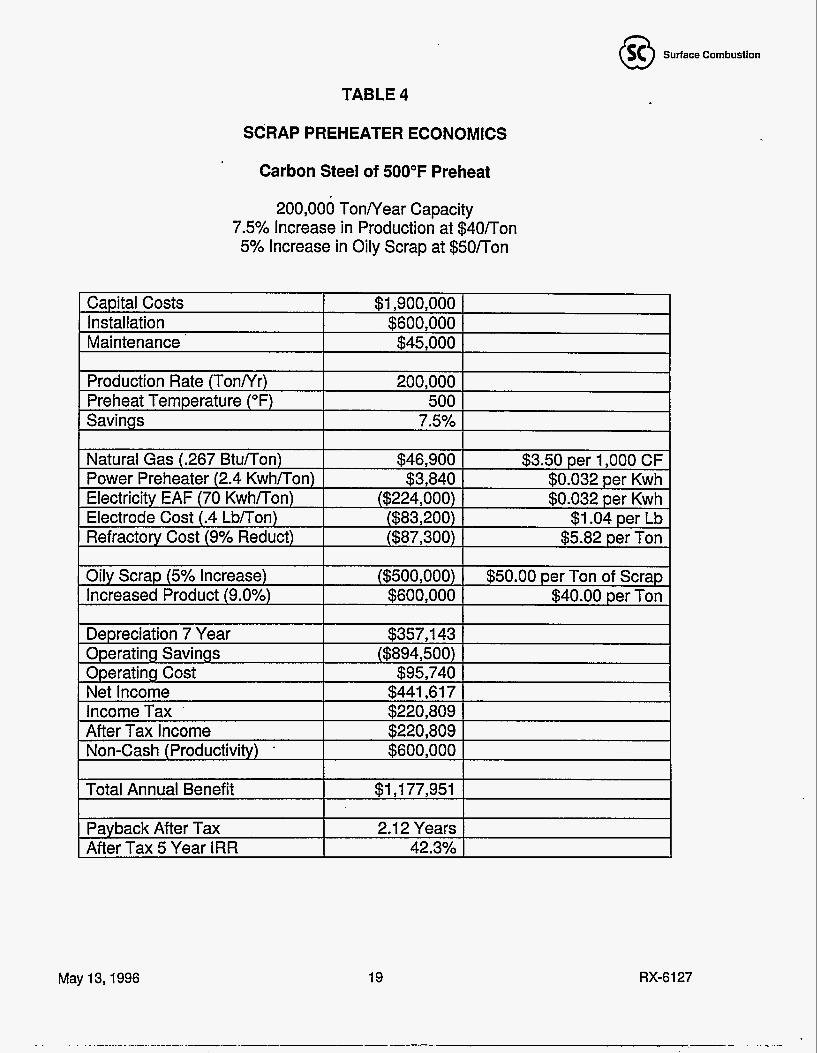
Surface Combustion Q9 TABLE 4
SCRAP PREHEATER ECONOMICS
Carbon Steel of 500°F Preheat
200,000 TonNear Capacity 7.5% Increase in Production at $40/Ton 5% Increase in Oily Scrap at $50/Ton
Capital Costs $1,900,000 Installation $600.000
1 - ~ -
Maintenance . $45,000 I
Production Rate (TonNr) 200,000 Preheat Temperature ( O F ) 500 Savinas 7.5%
Natural Gas (.267 BtulTon) $46,900 $3.50 per 1,000 CF Power Preheater (2.4 Kwh/Ton) $3,840 $0.032 per Kwh Electricity EAF (70 Kwh/Ton) ($224,000) $0.032 per Kwh Electrode Cost (.4 Lb/Ton) ($83,200) $1.04 per Lb Refractory Cost (9% Reduct) ($87,300) $5.82 per Ton
Oily Scrap (5% Increase) ($500,000) $50.00 per Ton of Scrap Increased Product (9.0%) $600,000 $40.00 per Ton
Depreciation 7 Year $357,143 Operating Savings ($894,500) Operating Cost $95,740 Net Income $441,617 IncomeTax ' $220 , 809 After Tax Income $220,809 Non-Cash (Productivity) . $600,000
Total Annual Benefit $1,177,951 I I . I
~
Payback After Tax After Tax 5 Year IRR
2.1 2 Years 42.3%
May 13,1996 19 RX-6127

Surface Combustion Q
COMPONENT
5.2 EMISSIONS
ESTIMATED EMISSION RATE I Maxm. Mass Rate
Tests during Phase II demonstrated that the preheater should have ve low VOC (volatile organic components), carbon monoxide, and particulate emission^?^'^. There may be small amounts of NOx, SOx, and HCI generated from components in the oils on the scrap. The results shown in Table 5 are for the preheater and do not include the arc furnace. Data are reported as uncorrected concentrations with oxygen contamination of 2%. The total effect on emission includes emissions from the preheater plus the emissions from the arc furnace.
TABLE 5
PROJECTED EMISSIONS FOR STAINLESS STEEL PREHEATER
Preheating reduces total wastes (gaseous emissions plus solids) in three ways:
1. Arc furnace emissions (Ib pollutant /ton of melted metal) are reduced because the furnace operates for a shorter time to melt the steel.
waste disposal problem. 2. When producing stainless steel, in-plant fines can be remelted, eliminating a solid
3. Since less electricity is required to melt a ton of steel, the power plant will produce lower emissions.
Although different arc furnaces may have different emissions, the data presented by ~
Geddis, R.R. et.al.’* was used as the base case for calculation of the reduction of wastes. Table 6 is based upon a preheater operating at 200,000 tons/year metal production and preheating to 900°F.
May 13,1996 20 RX-6127
I .

TABLE 6 WASTE REDUCTION
FOR COMBINED ARC FURNACE AND PREHEATER
Components
Arc Furnace NOx Preheater NOx Power Plant NOx TOTAL NOx
Surface Combustion 8
Arc Furnace Only With Preheater Preheater LblTon TonlYr LblTon TonlYr TonlYr
0.4 40 0.3 34 0.02 2
2.5 250 2.25 225 290 261 29
I ArcFurnace 14,15 I Waste 1 BaseCase
voc co Solids
0.1 5 15 15 3.0 300 250 50
600 2.5 600
VOC is volatile organic component. Solids are oily grinding produced during manufacture of stainless steel. These are currently sent off-site for disposal. It is assumed the power plant produces 0.005 Ib NOx/Kw generated and the preheater motors consumes 0.1 2 KwhlTon molten metal.
5.3 EVALUATION OF APPLICABILITY OF TECHNOLOGY
The proposed approach to scrap preheating offers solutions to the perceived problems with other available preheating systems for retrofit applications. The major objections raised by potential users were in four areas.
1. Problems Relatina To Incomplete Preheating. Most of the existing units that preheat in the scrap bucket use the arc furnace off gases as the only source of energy. There is generally insufficient time and energy to preheat the entire contents of the bucket. When there are organics remaining in the bucket, it can smoke as it is being moved to the arc furnace. There is concern that the smoke may contain harmful components including carcinogens and/or dioxin.
We have countered that using natural gas as the primary energy source will allow preheating of the entire bucket, removing of all the organics fully preheated buckets should not smoke. This has not been confirmed by testing.
2. Does Not Utilize The "Free" Enerqv Available From The Arc Furnace. Analysis of the economics in section 4.1 shows that the energy cost for operation of the afterburner is relatively small compared to the other cost savings. However, a "hybred" unit that using arc furnace off gas supplemented with natural gas may have more market appeal.
May 13,1996 21 RX-6127

@ Surface Combustion
3. Uncertaintv Relatina To Required Bucket Modification And Life Of Preheated Buckets. A typical melt shop will have eight to fifteen scrap buckets that are used in normal operations. They cost approximately $100,000 each. The bottom of the bucket has a "clam shell" that opens to allow the scrap to fall into the arc furnace. Often, the locking mechanism fails and so the bottom of the clan shell is held together with rope which burns when the bucket is over the hot arc furnace. With the preheater, it will be necessary to keep the locking mechanism in good repair.
The scrap buckets generally have an attached bail that is used to lift the buckets. The preheater requires that the bail be changed so it can be removed during preheating. The mill cranes handle other vessels with removable bails so this has not been a particular concern. However, the life of the bucket has been a concern. Heated buckets may tend to deform with use and may require more frequent replacement. There is no quantitative data available in this area.
4. Economics. The economic analysis in section 4.1 indicates that the system has a 1.5 to 2.5 year payback. This is based upon being able to take full advantage of the savings categories, especially increased productivity and lower cost scrap. The payback is at the upper end of acceptability, and would be unacceptable if both of the major savings can not be utilized. There was also a concern that the cost of oily scrap would increase if there was a demand created by preheating.
It will be necessary to include "intangibles" such as lower emissions, safety from removing water (ice) from the scrap, and smoother operations as part of the justification for investment in a preheater system.
5.4 RECOMMENDATIONS
We recommend that the program be placed "on the shelf" for three to five years. After that time the market conditions should be reevaluated for applicability of this system.
If the following factors are true this approach to preheating should be reevaluated.
1. Demand for increased production from existing mini-mills. 2. More lower quality (lower cost) scrap is available due to increased recycle. 3. Cost of electricity (and demand charges) are increasing. 4. There is a general acceptance of the idea of preheating in the United States.
If this program is reconsidered there are several technical areas that could be considered.
May 13,1996 22 RX-6127

Surface Combustion 8 1. Galvanized Scrap. Auto scrap has a growing amount of galvanized material. Today
the zinc from galvanized scrap ends up in the baghouses and renders arc furnace dust a hazardous waste. Zinc metal is volatile and can leave the arc furnace as a zinc vapor or very fine zinc oxide dust formed from vaporous zinc. Preheating will oxidize the zinc before it reaches the arc furnace and should reduce the amount of zinc in the arc furnace dust. Tests and/or operating data from other preheaters will be required to confirm this idea.
It would also be possible to preheat the scrap in a “reducing” atmosphere which ’ would vaporize the zinc and remove it from the scrap without oxidizing it. It could
then be removed from the gas stream as zinc metal. This would require some changes in the preheating system. When combined with preheating, thermal zinc removal may be an economical approach.
2. Tin Plate. Recycling is providing more tin plate material (cans). Preheating also oxidizes the tin which may reduce the amount of tin in the molten metal. Again testing and/or operating data are required to confirm this idea.
3. Dirty Scrap. Painted scrap or scrap coated with organics are excellent charges for the preheater because the organics are used as energy in preheating. Trends in availability and cost of this scrap should be determined.
4. Direct Reduced Iron (DRI). It is necessary to confirm the ability to preheat DRI. DRI has a very high surface area and can literally ignite under the right conditions.
5. Separate Preheatina Chamber. The original concept did not heat scrap in the scrap bucket, there was a separate refractory lined chamber to preheat the scrap by recirculating hot gases. The hot scrap was then dumped into the bucket. Although material handling is more complex when using a separate preheating chamber, problems relating to bucket modifications and bucket life are eliminated. A separate chamber may be required if process modifications such as zinc or tin removal are incorporated.
If the project is revitalized, one the early steps should be finding a mini-mill who is interested in being a host site. This is the “acid test” for the system. If no one is interested it is a sign of limited market acceptance.
May 13,1996 23 RX-6127

Surface Cornbustion 8 LITERATURE CITED
1
2
3
4
5
6
7
8
9
10
11
12
13
14
15
“Technoeconomic Assessment of Electric Steel Making Through the Year 2000.” Final report of the U.S. Department of Energy and the Electric Power Research Institute Project 2787-2, prepared by the center for Metals Production, Pittsburgh, October, 1987.
Surface Combustion, Inc. “Ferrous Scrap Preheating System”, Phase I Report, June, 1990.
Surface Combustion, Inc. “Ferrous Scrap Preheating System”, Phase I1 Report for U.S. Department of Energy Contract DE-AC02-89CE40874, November 23,1993.
Mclntyre, E.H., Goodwill, J.E. and Klesser, D.E. “The Challenge of Improving Electric Arc Furnace Efficiency”. Page 28-33 Iron and Steel Enaineer, May 1994.
Liebman, March, Clar, Richard, Bherklie, John, and Price, David. “An Assessment of the Prospects for Adopting Steel scrap Preheating in the United States”. Electric Furnace Conference Proceedings, 47 Orlando 1989.
Read, B.B. “Flat Rolled Minis, High Grade Scrap and One Question” American Metal Market {Steel MonthMA Page 5A. February 8,1995.
Prakash, S.N. “Ferrous Scrap Preheating Reduces Energy and Pollution Control Costs.” International Conference on Minimizing Energy Cost in Air Pollution Control Systems. Pittsburgh, April 1985.
McManus, G. J. “Scrap Preheating: A Trend Gains Momentum”, pages 60 and 61 , Iron and Steel Enaineer, August, 1995.
Hess, G.W. “Sheer Ingenuity Cuts Electric Costs”, Iron Aae, pages 14-16, October 1991 ,. Robertson, Scott “Two Vessels, Four Electrodes” New Steel, pages 48-51 , October, 1994.
New Steel “Iron Age Scrap Price Bulletin”, page 38, October 1995.
Surface Combustion, Inc. “Ferrous Scrap Preheating Emissions Characterization Test Report” Phase II Topical Report, October 13,1992.
Schultz, T.J. and Shah, J.K. “Waste UtilizationlRecovery by Preheating Ferrous Scrap”. Proceedings of 11 th Annual Incineration Conference, Albuquerque, New Mexico, May 1992.
Geddis, R.R., Chaltant, R.V. and Langel, W.A. “CO, VOC. and NO, Emission Factors For Electric Arc Furnaces” Paper No. 93-WA-81.03 presented at 86th Annual Meeting & Exposition, Air and Waste Management Association, June 1993.
Barnard, W.R., “Emission Factors For Iron and Steel Sources - Criteria and Toxic Pollutants”, U.S. Environmental Protection Agency.
5/6/96 TJS:as TJS-R001.96
May 13,1996 24 RX-6127