
Ferrites and accessories - Packing€¦ · Blister tape Standard tray 3.2 2.2.1 7 5 PQ cores PQ 16...
18
EPCOS AG 2017. Reproduction, publication and dissemination of this publication, enclosures hereto and the information contained therein without EPCOS’ prior express consent is prohibited. EPCOS AG is a TDK Group Company. Ferrites and accessories Packing Date: May 2017
Transcript of Ferrites and accessories - Packing€¦ · Blister tape Standard tray 3.2 2.2.1 7 5 PQ cores PQ 16...
EPCOS AG 2017. Reproduction, publication and dissemination of this publication, enclosures hereto and theinformation contained therein without EPCOS’ prior express consent is prohibited.
EPCOS AG is a TDK Group Company.
Ferrites and accessories
Packing
Date: May 2017
2 5/17Please read Cautions and warnings and Important notes at the end of this document.
Packing
Packing
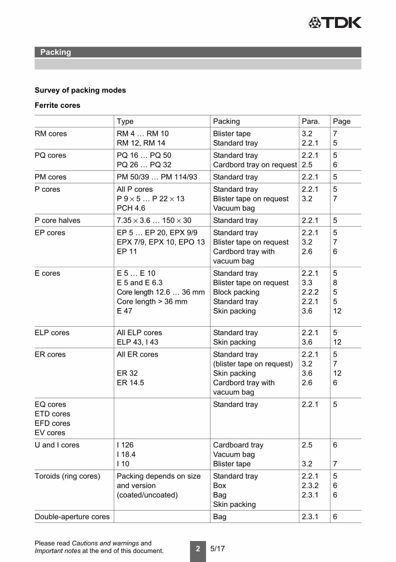
Survey of packing modes
Ferrite cores
Type Packing Para. PageRM cores RM 4 … RM 10
RM 12, RM 14Blister tapeStandard tray
3.22.2.1
75
PQ cores PQ 16 … PQ 50PQ 26 … PQ 32
Standard trayCardbord tray on request
2.2.12.5
56
PM cores PM 50/39 … PM 114/93 Standard tray 2.2.1 5P cores All P cores
P 9 × 5 … P 22 × 13PCH 4.6
Standard trayBlister tape on requestVacuum bag
2.2.13.2
57
P core halves 7.35 × 3.6 … 150 × 30 Standard tray 2.2.1 5EP cores EP 5 … EP 20, EPX 9/9
EPX 7/9, EPX 10, EPO 13EP 11
Standard trayBlister tape on requestCardbord tray with vacuum bag
2.2.13.22.6
576
E cores E 5 … E 10E 5 and E 6.3Core length 12.6 … 36 mmCore length > 36 mmE 47
Standard trayBlister tape on requestBlock packingStandard traySkin packing
2.2.13.32.2.22.2.13.6
585512
ELP cores All ELP coresELP 43, I 43
Standard traySkin packing
2.2.13.6
512
ER cores All ER cores
ER 32ER 14.5
Standard tray(blister tape on request)Skin packingCardbord tray with vacuum bag
2.2.13.23.62.6
57126
EQ coresETD coresEFD coresEV cores
Standard tray 2.2.1 5
U and I cores I 126I 18.4I 10
Cardboard trayVacuum bagBlister tape
2.5
3.2
6
7Toroids (ring cores) Packing depends on size
and version(coated/uncoated)
Standard trayBoxBagSkin packing
2.2.12.3.22.3.1
566
Double-aperture cores Bag 2.3.1 6
3 5/17Please read Cautions and warnings and Important notes at the end of this document.
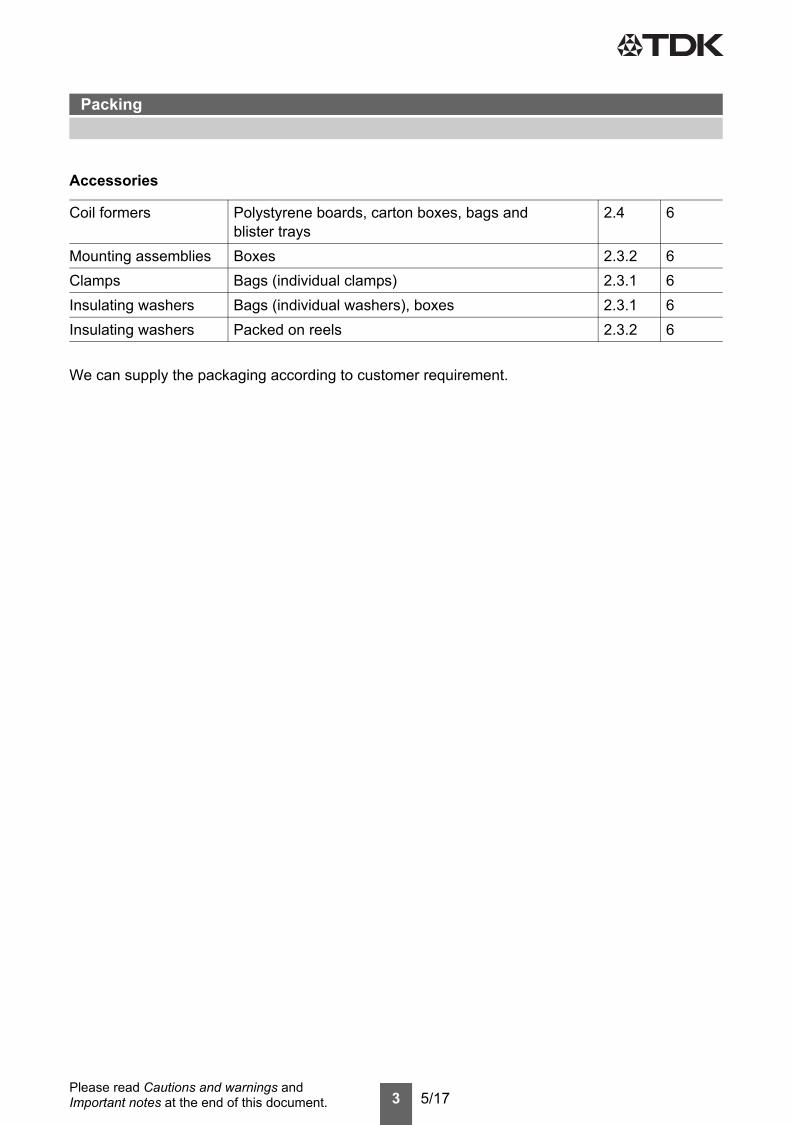
Accessories
We can supply the packaging according to customer requirement.
Coil formers Polystyrene boards, carton boxes, bags andblister trays
2.4 6
Mounting assemblies Boxes 2.3.2 6Clamps Bags (individual clamps) 2.3.1 6Insulating washers Bags (individual washers), boxes 2.3.1 6Insulating washers Packed on reels 2.3.2 6
Packing
4 5/17Please read Cautions and warnings and Important notes at the end of this document.
1 General informationOur product packaging modes ensure maximum protection against damage during transportation.Moreover, our packing materials are selected with environmental considerations in mind. They aremarked with the appropriate recycling symbols.Because of the large variety of types and sizes, we use five basic kinds of packing, which are de-scribed in points 2 and 3 below:■ Blister tape■ Tray■ Container■ Reel■ MagazineThe packing units are based on the following system:
1.1 Packing unit (PU)Usually, a packing unit is a collection of a number of basic packages. The size of the packing unitis stated for the particular components in their data sheets. When ordering, please state completepacking units if possible. We reserve the right to round the ordered quantity accordingly.
1.2 Dispatch unitA number of packing units are combined to form a dispatch unit. Standard dispatch units for largequantities are a Europallet or pallet carton. For small quantities, folding corrugated cardboard boxesare used in standard sizes. In the case of small quantities a dispatch unit may also include packageswith other components.
1.3 Barcode labelOn the product packing label (standard label) we include bar-code information in addition to plaintext. In addition to benefits relating to the internal flow of goods, this provides above all a more rapidand error-free means of identification checking for the customer.
Packing
5 5/17Please read Cautions and warnings and Important notes at the end of this document.
2 Modes of packing2.1 Blister tapeBlister packing was specially devised for handling by automatic systems but has also proved to bevery good for conventional handling, especially where small quantities are concerned. See point 3.2for a detailed description and a list of the core types that can be supplied in this type of packing.
2.2 Tray (pallet)2.2.1 Standard trayThe polystyrene tray (basic package) is the standard packing for most types of core. The area of200 mm × 300 mm corresponds to the module dimensions of DIN 55 510 and is based on the areaof the 800 mm × 1200 mm Europallet. Depending on the overall height of the trays and the numberscontained, several trays will be stacked to form a packing unit and provided with a corrugated card-board cover. For the protection of the cores the entire stack is also shrink-wrapped in polyethylenefilm.Each core is enclosed in a separate compartment. When P cores and similar types are packed insets, the halves of the core pairs are packed so that their pole faces are opposite one another. Asa rule their association is identified by markings in the polystyrene (recessed webs, thinner webs).In the case of P 3.3 × 2.6 and P 4.6 × 4.1 cores the halves of a set are not located in a single traybut in different trays of a packing unit.
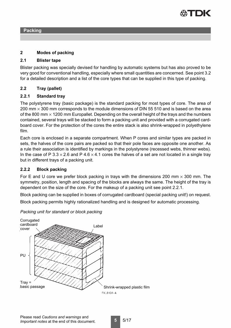
2.2.2 Block packingFor E and U core we prefer block packing in trays with the dimensions 200 mm × 300 mm. Thesymmetry, position, length and spacing of the blocks are always the same. The height of the tray isdependent on the size of the core. For the makeup of a packing unit see point 2.2.1.Block packing can be supplied in boxes of corrugated cardboard (special packing unit!) on request.Block packing permits highly rationalized handling and is designed for automatic processing.
Packing unit for standard or block packing
Label
Shrink-wrapped plastic film
Corrugated
PU
Tray =basic passage
cardboardcover
Packing
6 5/17Please read Cautions and warnings and Important notes at the end of this document.
2.3 Container2.3.1 BagSmall ferrite parts are packed in flat polyethylene vacuum bags. The number per bag depends onthe volume of the parts. Generally four bags in a corrugated cardboard box form a packing unit.Small accessories (clamps, pinless and SMD coil formers) are also packed in this way. The size ofthe bag depends on the volume of the parts (packing unit).
2.3.2 BoxesCoated ring cores of medium size are packed in cardboard boxes with cardboard or polyethylenefoam inlays. The number per box depends on the volume of the cores.Accessories (large mounting assemblies, clamps, washers packed on reels etc.) are packed inboxes of cardboard or corrugated cardboard.
2.4 Packing for coil formersFor coil formers we use different packing types depending on size, pin type and packing equipment.So we use polystyrene boards for some PTH coil formers like RM types. For most of the other PTHcoil formers and some SMD coil formers we use cardboard boxes as bulk packaging. Coil formerswithout pins are mainly packed in plastic bags. For some SMD coil formers we also use blister traypackaging.
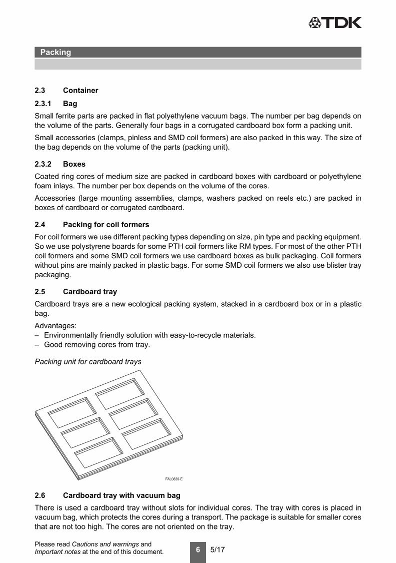
2.5 Cardboard trayCardboard trays are a new ecological packing system, stacked in a cardboard box or in a plasticbag.Advantages:– Environmentally friendly solution with easy-to-recycle materials.– Good removing cores from tray.
2.6 Cardboard tray with vacuum bagThere is used a cardboard tray without slots for individual cores. The tray with cores is placed invacuum bag, which protects the cores during a transport. The package is suitable for smaller coresthat are not too high. The cores are not oriented on the tray.
Packing unit for cardboard trays
Packing
7 5/17Please read Cautions and warnings and Important notes at the end of this document.
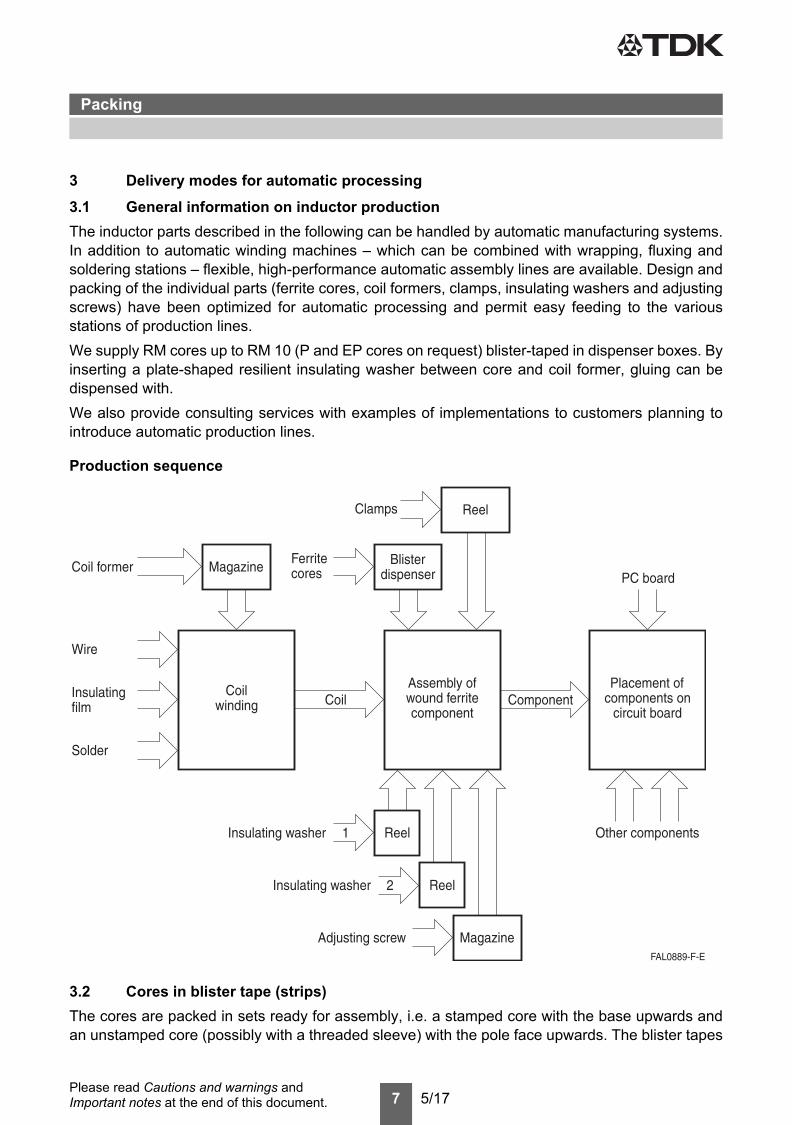
3 Delivery modes for automatic processing3.1 General information on inductor productionThe inductor parts described in the following can be handled by automatic manufacturing systems.In addition to automatic winding machines – which can be combined with wrapping, fluxing andsoldering stations – flexible, high-performance automatic assembly lines are available. Design andpacking of the individual parts (ferrite cores, coil formers, clamps, insulating washers and adjustingscrews) have been optimized for automatic processing and permit easy feeding to the variousstations of production lines.We supply RM cores up to RM 10 (P and EP cores on request) blister-taped in dispenser boxes. Byinserting a plate-shaped resilient insulating washer between core and coil former, gluing can bedispensed with.We also provide consulting services with examples of implementations to customers planning tointroduce automatic production lines.
Production sequence
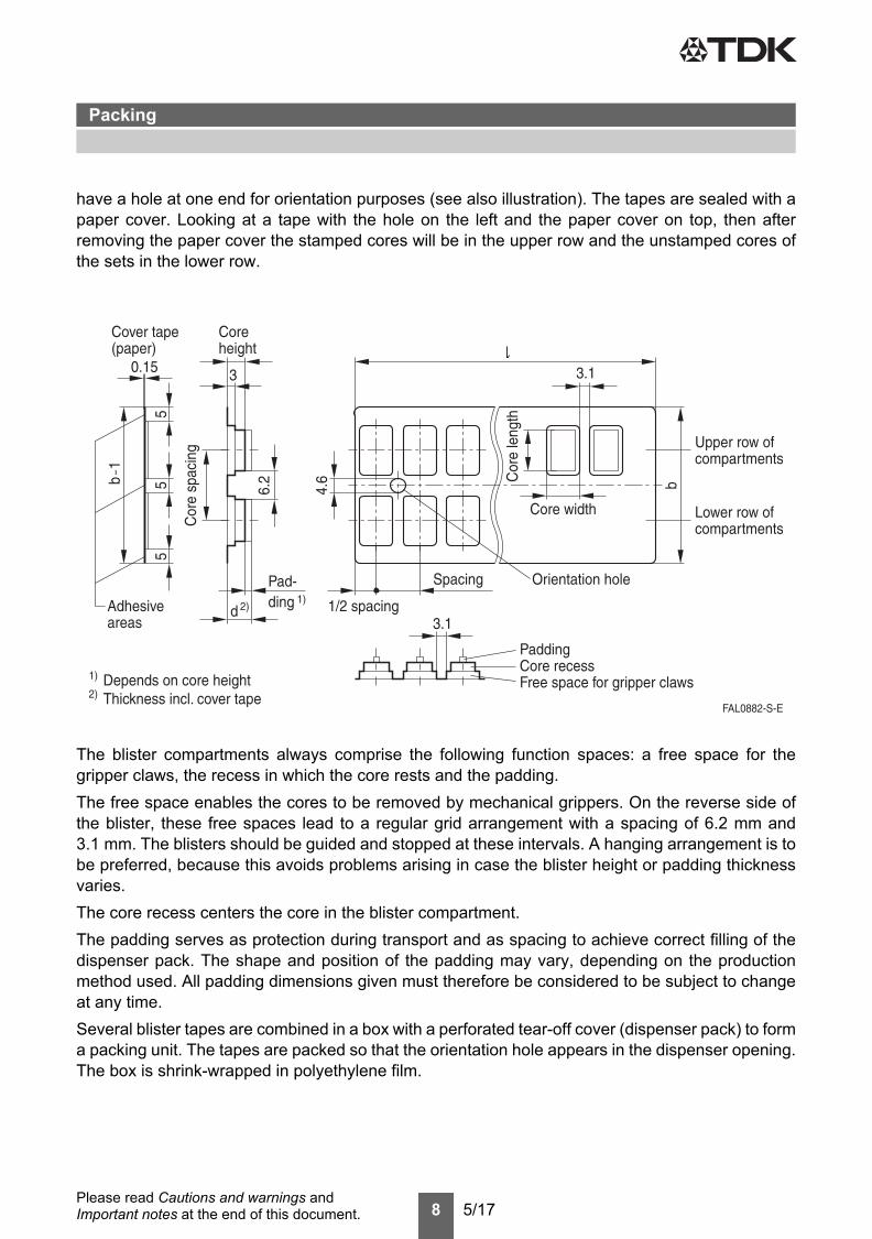
3.2 Cores in blister tape (strips)The cores are packed in sets ready for assembly, i.e. a stamped core with the base upwards andan unstamped core (possibly with a threaded sleeve) with the pole face upwards. The blister tapes
Packing
8 5/17Please read Cautions and warnings and Important notes at the end of this document.
have a hole at one end for orientation purposes (see also illustration). The tapes are sealed with apaper cover. Looking at a tape with the hole on the left and the paper cover on top, then afterremoving the paper cover the stamped cores will be in the upper row and the unstamped cores ofthe sets in the lower row.
The blister compartments always comprise the following function spaces: a free space for thegripper claws, the recess in which the core rests and the padding.The free space enables the cores to be removed by mechanical grippers. On the reverse side ofthe blister, these free spaces lead to a regular grid arrangement with a spacing of 6.2 mm and3.1 mm. The blisters should be guided and stopped at these intervals. A hanging arrangement is tobe preferred, because this avoids problems arising in case the blister height or padding thicknessvaries.The core recess centers the core in the blister compartment.The padding serves as protection during transport and as spacing to achieve correct filling of thedispenser pack. The shape and position of the padding may vary, depending on the productionmethod used. All padding dimensions given must therefore be considered to be subject to changeat any time.Several blister tapes are combined in a box with a perforated tear-off cover (dispenser pack) to forma packing unit. The tapes are packed so that the orientation hole appears in the dispenser opening.The box is shrink-wrapped in polyethylene film.
Packing
9 5/17Please read Cautions and warnings and Important notes at the end of this document.
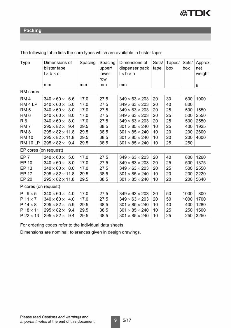
The following table lists the core types which are available in blister tape:
For ordering codes refer to the individual data sheets.Dimensions are nominal; tolerances given in design drawings.
Type Dimensions ofblister tapel × b × d
mm
Spacing
mm
Spacingupper/lowerrowmm
Dimensions ofdispenser packl × b × h
mm
Sets/tape
Tapes/box
Sets/box
Approx.netweight
gRM coresRM 4RM 4 LPRM 5RM 6R 6 RM 7RM 8RM 10RM 10 LP
340 × 60 × 6.6340 × 60 × 5.0340 × 60 × 8.0340 × 60 × 8.0340 × 60 × 8.0295 × 82 × 9.4295 × 82 × 11.8295 × 82 × 11.8295 × 82 × 9.4
17.017.017.017.017.029.529.529.529.5
27.527.527.527.527.538.538.538.538.5
349 × 63 × 203349 × 63 × 203349 × 63 × 203349 × 63 × 203349 × 63 × 203301 × 85 × 240301 × 85 × 240301 × 85 × 240301 × 85 × 240
202020202010101010
304025252525202025
600800500500500400200200250
1000
155025502550192526004600
EP cores (on request)EP 7EP 10EP 13 EP 17EP 20
340 × 60 × 5.0340 × 60 × 8.0340 × 60 × 8.0295 × 82 × 11.8295 × 82 × 11.8
17.017.017.029.529.5
27.527.527.538.538.5
349 × 63 × 203349 × 63 × 203349 × 63 × 203301 × 85 × 240301 × 85 × 240
2020201010
4025252020
800500500200200
12601375255022205640
P cores (on request)P 9 × 5P 11 × 7P 14 × 8P 18 × 11P 22 × 13
340 × 60 × 4.0340 × 60 × 4.0295 × 82 × 5.9295 × 82 × 9.4295 × 82 × 9.4
17.017.029.529.529.5
27.527.538.538.538.5
349 × 63 × 203349 × 63 × 203301 × 85 × 240301 × 85 × 240301 × 85 × 240
2020101010
5050402525
10001000
400250250
8001700128015003250
Packing
10 5/17Please read Cautions and warnings and Important notes at the end of this document.
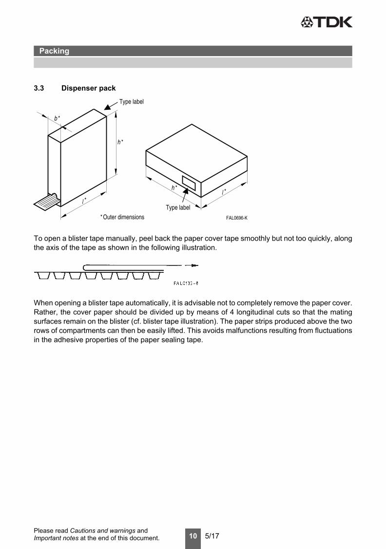
3.3 Dispenser pack
To open a blister tape manually, peel back the paper cover tape smoothly but not too quickly, alongthe axis of the tape as shown in the following illustration.
When opening a blister tape automatically, it is advisable not to completely remove the paper cover.Rather, the cover paper should be divided up by means of 4 longitudinal cuts so that the matingsurfaces remain on the blister (cf. blister tape illustration). The paper strips produced above the tworows of compartments can then be easily lifted. This avoids malfunctions resulting from fluctuationsin the adhesive properties of the paper sealing tape.
Packing
11 5/17Please read Cautions and warnings and Important notes at the end of this document.
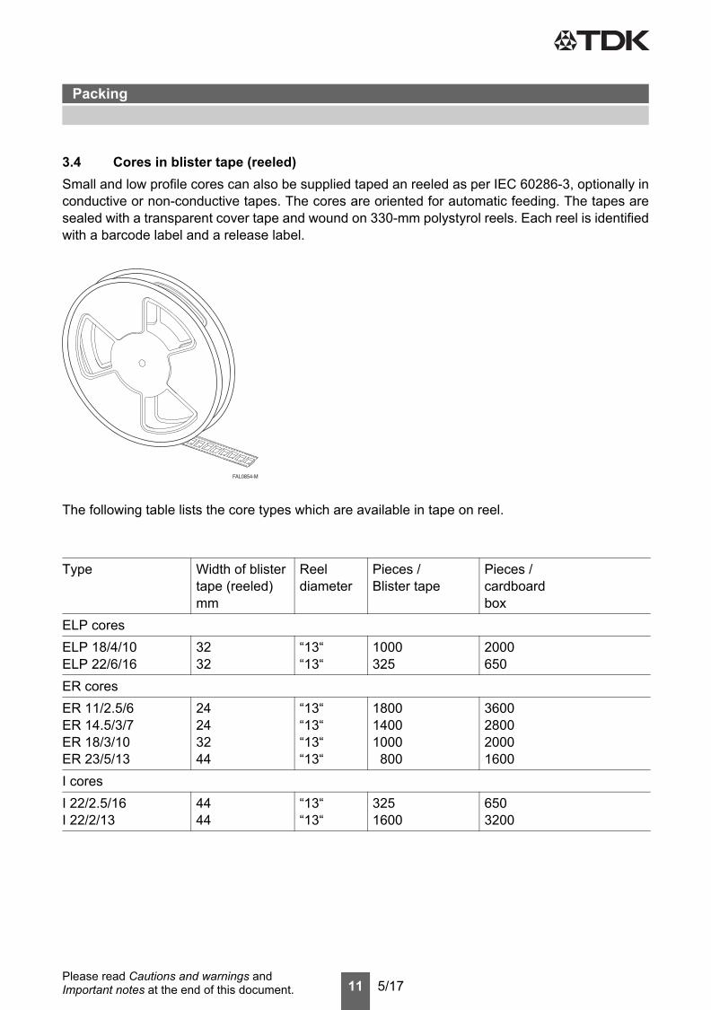
3.4 Cores in blister tape (reeled)Small and low profile cores can also be supplied taped an reeled as per IEC 60286-3, optionally inconductive or non-conductive tapes. The cores are oriented for automatic feeding. The tapes aresealed with a transparent cover tape and wound on 330-mm polystyrol reels. Each reel is identifiedwith a barcode label and a release label.
The following table lists the core types which are available in tape on reel.
Type Width of blister tape (reeled) mm
Reel diameter
Pieces /Blister tape
Pieces / cardboardbox
ELP coresELP 18/4/10ELP 22/6/16
3232
“13““13“
1000325
2000650
ER coresER 11/2.5/6ER 14.5/3/7ER 18/3/10ER 23/5/13
24243244
“13““13““13““13“
180014001000 800
3600280020001600
I coresI 22/2.5/16I 22/2/13
4444
“13““13“
3251600
6503200
Packing
12 5/17Please read Cautions and warnings and Important notes at the end of this document.
Packing
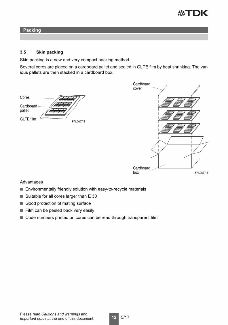
3.5 Skin packingSkin packing is a new and very compact packing method.Several cores are placed on a cardboard pallet and sealed in GLTE film by heat shrinking. The var-ious pallets are then stacked in a cardboard box.
Advantages■ Environmentally friendly solution with easy-to-recycle materials■ Suitable for all cores larger than E 30■ Good protection of mating surface■ Film can be peeled back very easily■ Code numbers printed on cores can be read through transparent film
13 5/17Please read Cautions and warnings and Important notes at the end of this document.
Mechanical stress and mountingFerrite cores have to meet mechanical requirements during assembling and for a growing numberof applications. Since ferrites are ceramic materials one has to be aware of the special behaviorunder mechanical load.As valid for any ceramic material, ferrite cores are brittle and sensitive to any shock, fast tempera-ture changing or tensile load. Especially high cooling rates under ultrasonic cleaning and high staticor cyclic loads can cause cracks or failure of the ferrite cores.For detailed information see data book, chapter “General - Definitions, 8.1”.
Effects of core combination on AL value Stresses in the core affect not only the mechanical but also the magnetic properties. It is apparentthat the initial permeability is dependent on the stress state of the core. The higher the stresses arein the core, the lower is the value for the initial permeability. Thus the embedding medium shouldhave the greatest possible elasticity.For detailed information see data book, chapter “General - Definitions, 8.1”.
Heating upFerrites can run hot during operation at higher flux densities and higher frequencies.
NiZn-materials The magnetic properties of NiZn-materials can change irreversible in high magnetic fields.
Ferrite AccessoriesEPCOS ferrite accessories have been designed and evaluated only in combination with EPCOSferrite cores. EPCOS explicitly points out that EPCOS ferrite accessories or EPCOS ferrite coresmay not be compatible with those of other manufacturers. Any such combination requires prior te-sting by the customer and will be at the customer‘s own risk.EPCOS assumes no warranty or reliability for the combination of EPCOS ferrite accessories withcores and other accessories from any other manufacturer.
Processing remarksThe start of the winding process should be soft. Else the flanges may be destroyed.– Too strong winding forces may blast the flanges or squeeze the tube that the cores can not be
mounted any more.– Too long soldering time at high temperature (>300 °C) may effect coplanarity or pin arrange-
ment.– Not following the processing notes for soldering of the J-leg terminals may cause solderability
problems at the transformer because of pollution with Sn oxyde of the tin bath or burned insula-tion of the wire. For detailed information see chapter “Processing notes”, section 2.2.
– The dimensions of the hole arrangement have fixed values and should be understood asa recommendation for drilling the printed circuit board. For dimensioning the pins, the groupof holes can only be seen under certain conditions, as they fit into the given hole arrangement.To avoid problems when mounting the transformer, the manufacturing tolerances for positioning the customers’ drilling process must be considered by increasing the hole diameter.
Cautions and warningsFerrites and accessories
Cautions and warnings
14 5/17Please read Cautions and warnings and Important notes at the end of this document.
Ferrites and accessories
Display of ordering codes for EPCOS productsThe ordering code for one and the same product can be represented differently in data sheets, data books, other publications and the website of EPCOS, or in order-related documents such asshipping notes, order confirmations and product labels. The varying representations of the ordering codes are due to different processes employed and do not affect the specifications of the respective products. Detailed information can be found on the Internet under www.epcos.com/orderingcodes.
Cautions and warnings
15 5/17Please read Cautions and warnings and Important notes at the end of this document.
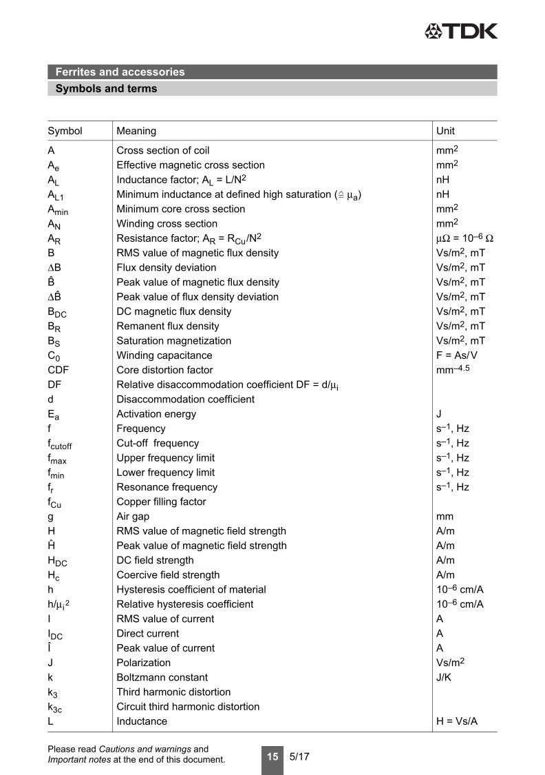
Symbol Meaning Unit
AAeALAL1AminANARBΔBB ΔB BDCBRBSC0CDFDFdEaffcutofffmaxfminfrfCugHH HDCHchh/μi 2
IIDCIJkk3k3cL
Cross section of coilEffective magnetic cross sectionInductance factor; AL = L/N2
Minimum inductance at defined high saturation ( μa)Minimum core cross sectionWinding cross sectionResistance factor; AR = RCu/N2
RMS value of magnetic flux densityFlux density deviationPeak value of magnetic flux densityPeak value of flux density deviationDC magnetic flux densityRemanent flux densitySaturation magnetizationWinding capacitanceCore distortion factorRelative disaccommodation coefficient DF = d/μiDisaccommodation coefficientActivation energyFrequencyCut-off frequencyUpper frequency limitLower frequency limitResonance frequencyCopper filling factorAir gapRMS value of magnetic field strengthPeak value of magnetic field strengthDC field strengthCoercive field strengthHysteresis coefficient of materialRelative hysteresis coefficientRMS value of currentDirect currentPeak value of currentPolarizationBoltzmann constantThird harmonic distortionCircuit third harmonic distortionInductance
mm2
mm2
nHnHmm2
mm2
μΩ = 10–6 ΩVs/m2, mTVs/m2, mTVs/m2, mTVs/m2, mTVs/m2, mTVs/m2, mTVs/m2, mTF = As/Vmm–4.5
Js–1, Hzs–1, Hzs–1, Hzs–1, Hzs–1, Hz
mmA/mA/mA/mA/m10–6 cm/A10–6 cm/AAAAVs/m2
J/K
H = Vs/A
Symbols and termsFerrites and accessories
Symbols and terms
16 5/17Please read Cautions and warnings and Important notes at the end of this document.
Symbol Meaning Unit
ΔL/LL0LHLpLrevLslelNNPCuPtransPVPFQRRCuRhΔRhRiRpRsRthRVsTΔTTCttvtan δtan δLtan δrtan δetan δhtan δ/μiUÛVeZZn
Relative inductance changeInductance of coil without coreMain inductanceParallel inductanceReversible inductanceSeries inductanceEffective magnetic path lengthAverage length of turnNumber of turnsCopper (winding) lossesTransferrable powerRelative core lossesPerformance factorQuality factor (Q = ωL/Rs = 1/tan δL)ResistanceCopper (winding) resistance (f = 0)Hysteresis loss resistance of a coreRh changeInternal resistanceParallel loss resistance of a coreSeries loss resistance of a coreThermal resistanceEffective loss resistance of a coreTotal air gapTemperatureTemperature differenceCurie temperatureTimePulse duty factorLoss factorLoss factor of coil(Residual) loss factor at H → 0Relative loss factorHysteresis loss factorRelative loss factor of material at H → 0RMS value of voltagePeak value of voltageEffective magnetic volumeComplex impedanceNormalized impedance |Z|n = |Z| /N2 × ε (le/Ae)
HHHHHHmmmm
WWmW/g
ΩΩΩΩΩΩΩK/WΩmm°CK°Cs
VVmm3
ΩΩ/mm
Symbols and termsFerrites and accessories
17 5/17Please read Cautions and warnings and Important notes at the end of this document.
All dimensions are given in mm.
Surface-mount device
Symbol Meaning Unit
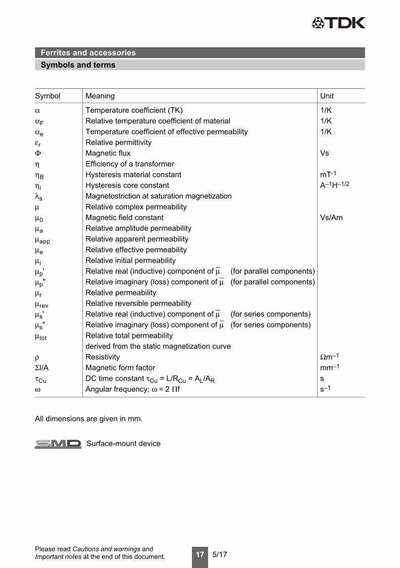
ααFαeεrΦηηBηiλsμμ0μaμappμeμiμp'μp"μrμrevμs'μs"μtot
ρΣl/AτCuω
Temperature coefficient (TK)Relative temperature coefficient of materialTemperature coefficient of effective permeabilityRelative permittivityMagnetic fluxEfficiency of a transformerHysteresis material constantHysteresis core constantMagnetostriction at saturation magnetizationRelative complex permeabilityMagnetic field constantRelative amplitude permeabilityRelative apparent permeabilityRelative effective permeabilityRelative initial permeabilityRelative real (inductive) component of μ (for parallel components)Relative imaginary (loss) component of μ (for parallel components)Relative permeabilityRelative reversible permeabilityRelative real (inductive) component of μ (for series components)Relative imaginary (loss) component of μ (for series components)Relative total permeabilityderived from the static magnetization curveResistivityMagnetic form factorDC time constant τCu = L/RCu = AL/ARAngular frequency; ω = 2 Πf
1/K1/K1/K
Vs
mT-1
A–1H–1/2
Vs/Am
Ωm–1
mm–1
ss–1
Symbols and termsFerrites and accessories
18 5/17Please read Cautions and warnings and Important notes at the end of this document.
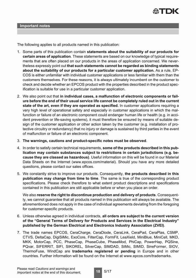
The following applies to all products named in this publication:
1. Some parts of this publication contain statements about the suitability of our products forcertain areas of application. These statements are based on our knowledge of typical require-ments that are often placed on our products in the areas of application concerned. We never-theless expressly point out that such statements cannot be regarded as binding statementsabout the suitability of our products for a particular customer application. As a rule, EP-COS is either unfamiliar with individual customer applications or less familiar with them than thecustomers themselves. For these reasons, it is always ultimately incumbent on the customer tocheck and decide whether an EPCOS product with the properties described in the product spec-ification is suitable for use in a particular customer application.
2. We also point out that in individual cases, a malfunction of electronic components or fail-ure before the end of their usual service life cannot be completely ruled out in the currentstate of the art, even if they are operated as specified. In customer applications requiring avery high level of operational safety and especially in customer applications in which the mal-function or failure of an electronic component could endanger human life or health (e.g. in acci-dent prevention or life-saving systems), it must therefore be ensured by means of suitable de-sign of the customer application or other action taken by the customer (e.g. installation of pro-tective circuitry or redundancy) that no injury or damage is sustained by third parties in the eventof malfunction or failure of an electronic component.
3. The warnings, cautions and product-specific notes must be observed.
4. In order to satisfy certain technical requirements, some of the products described in this pub-lication may contain substances subject to restrictions in certain jurisdictions (e.g. be-cause they are classed as hazardous). Useful information on this will be found in our MaterialData Sheets on the Internet (www.epcos.com/material). Should you have any more detailedquestions, please contact our sales offices.
5. We constantly strive to improve our products. Consequently, the products described in thispublication may change from time to time. The same is true of the corresponding productspecifications. Please check therefore to what extent product descriptions and specificationscontained in this publication are still applicable before or when you place an order.
We also reserve the right to discontinue production and delivery of products. Consequent-ly, we cannot guarantee that all products named in this publication will always be available. Theaforementioned does not apply in the case of individual agreements deviating from the foregoingfor customer-specific products.
6. Unless otherwise agreed in individual contracts, all orders are subject to the current versionof the “General Terms of Delivery for Products and Services in the Electrical Industry”published by the German Electrical and Electronics Industry Association (ZVEI).
7. The trade names EPCOS, CeraCharge, CeraDiode, CeraLink, CeraPad, CeraPlas, CSMP,CTVS, DeltaCap, DigiSiMic, ExoCore, FilterCap, FormFit, LeaXield, MiniBlue, MiniCell, MKD,MKK, MotorCap, PCC, PhaseCap, PhaseCube, PhaseMod, PhiCap, PowerHap, PQSine,PQvar, SIFERRIT, SIFI, SIKOREL, SilverCap, SIMDAD, SiMic, SIMID, SineFormer, SIOV,ThermoFuse, WindCap are trademarks registered or pending in Europe and in othercountries. Further information will be found on the Internet at www.epcos.com/trademarks.
Important notes


![000’(-...P7 Ł7 O PQ P ƒ7 Q P7 R S7 M12 ƒ[/ 012! P7 Ł7 O PQ? @7 O PQ V ₁12 X,2 / 012 &&" P7 Ł7 O PQ PH uH • MN2 uQ ó PQ è Q í @12 O PQ º ˇ7 u] &(& P7 Ł7 O PQ Y ⁄2](https://static.fdocuments.in/doc/165x107/5f061dee7e708231d4165fd6/000a-p7-7-o-pq-p-7-q-p7-r-s7-m12-012-p7-7-o-pq-7-o-pq-v-a12.jpg)