Ferrite coils support NFC circuits ideally - TDK … · Ferrite coils support NFC circuits ideally...
1 20151104 Multilayer Ferrite Coil MLJ Series Ferrite coils support NFC circuits ideally The number of smartphones and other compact mobile devices that are “NFC-compliant” or “NFC-equipped” is increasing. NFC is an abbreviation of Near Field Communication, a technology which enables an NFC- equipped device to communicate with a special reader/writer or another NFC-equipped device when the device is held over the reader/writer or is brought close to the other device, using radio waves at a frequency of 13.56MHz. Thanks to the adoption of a newly-developed low-loss ferrite material, TDK’s MLJ series multilayer ferrite coils now offer improved communication properties which are ideal for NFC-equipped devices, while featuring compact package sizes. Rapid worldwide adoption of NFC-equipped devices is forecast NFC, a technology invented more than 10 years ago, has been spreading rapidly throughout the world in recent years. In Japan, systems adopting non-contact type IC cards such as mobile payment systems, e-money, and payments at the ticket barriers of stations are already common, and they are also helping to expand the use of NFC functionality. It is expected that applications of NFC functionality will become more numerous throughout the world in the future, at the same time as the number of NFC-equipped devices in use grows. Figure 1 is a schematic diagram of a typical NFC circuit. An LC filter circuit made up of a coil and capacitor is inserted between the antenna and control IC. It is necessary to minimize variations between the inductance of the coil and the capacitance of the capacitor since they affect impedance matching. Also, a narrow tolerance (inductance value of ±5% or smaller) and properties that are stable even after going through a reflow furnace or current energization are required of the coil. Moreover, a high Q value is required since low loss is required at a communication frequency of 13.56MHz. TDK’s new multilayer ferrite coil, the MLJ1608 series, satisfies such requirements. The MLJ1608 series consists of coils that are optimally designed to offer the characteristics required by NFC
-
Upload
truongdien -
Category
Documents
-
view
222 -
download
0
Transcript of Ferrite coils support NFC circuits ideally - TDK … · Ferrite coils support NFC circuits ideally...

120151104
Multilayer Ferrite Coil MLJ Series
Ferrite coils support NFC circuits ideallyThe number of smartphones and other compact mobile devices that are “NFC-compliant” or “NFC-equipped” is increasing. NFC is an abbreviation of Near Field Communication, a technology which enables an NFC-equipped device to communicate with a special reader/writer or another NFC-equipped device when the device is held over the reader/writer or is brought close to the other device, using radio waves at a frequency of 13.56MHz. Thanks to the adoption of a newly-developed low-loss ferrite material, TDK’s MLJ series multilayer ferrite coils now offer improved communication properties which are ideal for NFC-equipped devices, while featuring compact package sizes.
Rapid worldwide adoption of NFC-equipped devices is forecast
NFC, a technology invented more than 10 years ago, has been spreading rapidly throughout the world in recent years. In Japan, systems adopting non-contact type IC cards such as mobile payment systems, e-money, and payments at the ticket barriers of stations are already common, and they are also helping to expand the use of NFC functionality. It is expected that applications of NFC functionality will become more numerous throughout the world in the future, at the same time as the number of NFC-equipped devices in use grows.
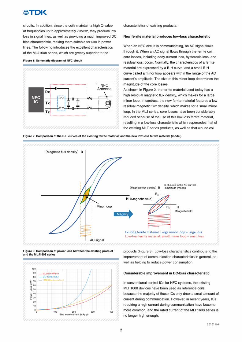
Figure 1 is a schematic diagram of a typical NFC circuit. An LC filter circuit made up of a coil and capacitor is inserted
between the antenna and control IC.
It is necessary to minimize variations between the inductance of the coil and the capacitance of the capacitor since they affect impedance matching. Also, a narrow tolerance (inductance value of ±5% or smaller) and properties that are stable even after going through a reflow furnace or current energization are required of the coil. Moreover, a high Q value is required since low loss is required at a communication frequency of 13.56MHz. TDK’s new multilayer ferrite coil, the MLJ1608 series, satisfies such requirements.
The MLJ1608 series consists of coils that are optimally designed to offer the characteristics required by NFC
220151104
circuits. In addition, since the coils maintain a high Q value at frequencies up to approximately 70MHz, they produce low loss in signal lines, as well as providing a much improved DC bias characteristic, making them suitable for use in power lines. The following introduces the excellent characteristics of the MLJ1608 series, which are greatly superior to the
characteristics of existing products.
New ferrite material produces low-loss characteristic
When an NFC circuit is communicating, an AC signal flows through it. When an AC signal flows through the ferrite coil, core losses, including eddy-current loss, hysteresis loss, and residual loss, occur. Normally, the characteristics of a ferrite material are expressed by a B-H curve, and a small B-H curve called a minor loop appears within the range of the AC current’s amplitude. The size of this minor loop determines the magnitude of the core losses. As shown in Figure 2, the ferrite material used today has a high residual magnetic flux density, which makes for a large minor loop. In contrast, the new ferrite material features a low residual magnetic flux density, which makes for a small minor loop. In the MLJ series, core losses have been considerably reduced because of the use of this low-loss ferrite material, resulting in a low-loss characteristic which supersedes that of the existing MLF series products, as well as that wound coil
products (Figure 3). Low-loss characteristics contribute to the improvement of communication characteristics in general, as well as helping to reduce power consumption.
Considerable improvement in DC-bias characteristic
In conventional control ICs for NFC systems, the existing MLF1608 devices have been used as reference coils, because the majority of these ICs only drew a small amount of current during communication. However, in recent years, ICs requiring a high current during communication have become more common, and the rated current of the MLF1608 series is no longer high enough.
Existing ferrite material: Large minor loop = large lossLow-loss ferrite material: Small minor loop = small loss
B
H
(Magnetic flux density)
(Magnetic field)
B-H curve in the AC current amplitude (model)
Ha
Ba
(Magnetic flux density)
Multilayer Ferrite Inductor
NFCAntenna
Wire Winding Ferrite Inductor
B
H(Magnetic field)
AC signal
Minor loop
Magnify
1200
900
600
300
0
H[A_per_meter]
Less leakage flux!!
RxNFCIC Tx
Tx
Figure 2: Comparison of the B-H curves of the existing ferrite material, and the new low-loss ferrite material (model)
Existing ferrite material: Large minor loop = large lossLow-loss ferrite material: Small minor loop = small loss
B
H
(Magnetic flux density)
(Magnetic field)
B-H curve in the AC current amplitude (model)
Ha
Ba
(Magnetic flux density)
Multilayer Ferrite Inductor
NFCAntenna
Wire Winding Ferrite Inductor
B
H(Magnetic field)
AC signal
Minor loop
Magnify
1200
900
600
300
0
H[A_per_meter]
Less leakage flux!!
RxNFCIC Tx
Tx
Figure 1: Schematic diagram of NFC circuit
Figure 3: Comparison of power loss between the existing product and the MLJ1608 series
0
10
20
30
40
50
60
70
80
90
100
0 100 200 300 400
Pow
er L
oss
( mW
)
Sine wave current (mAp-p)
MLJ1608WR56JMLF1608DR56J1608 Wire wound coil

320151104
those of a wire-wound coil thanks to the improvement in DC-bias characteristics (Figure 4).
Q characteristic: values in the conducting state are important
Since NFC operates at a frequency of 13.56 MHz, system designers require coils that exhibit high Q values at this frequency. Generally, the Q characteristic is described in catalogues, and there is no problem as long as the product is used at currents lower than the rated maximum. However, since a large current of up to 300 mA flows in an NFC circuit, the Q characteristic deteriorates if a general multilayer ferrite coil for signal lines is used. Therefore, the Q characteristic in a conducting state is important in an NFC circuit. As is shown in Figure 5, the Q characteristic of the MLJ series yields an extremely mild degradation curve and ensures a The MLJ series uses a newly developed low-loss high-
current ferrite material. This new ferrite material has DC-bias characteristics more than twice as good as those of the existing MLF series, while maintaining an equivalent performance level. Because of these improved DC-bias characteristics, the MLJ1608 series has been able to achieve a rated current greater than that of MLF2012 type, a device which is one size larger.
NFC circuits draw an AC current ranging from approximately 100 mA to 300 mA during communication. Over this range, the MLJ1608 series products exhibit characteristics equivalent to
characteristic equivalent or superior to that of the wire-wound coil products in the range of the current that flows in NFC circuits.
Comparison of coils’ communication characteristics
The MLJ series not only features superior characteristics as a coil, but exhibits excellent communication characteristics when used as a coil in NFC circuits as well. Tests conducted by the NFC Forum (an industry association that establishes technical or test specifications for NFC) have measurement points at 5 mm intervals on three axes (green dots in Figure 7). Figure 8 shows the result of the comparison of the voltages at Z = 5mm in the horizontal and vertical directions, as well as a comparison of the voltages at reference points up to 10mm (reference values), although the latter ones are out of
0
100
200
300
400
500
600
700
800
900
1000
0 200100 300 400 500
Indu
ctan
ce (n
H)
Current (mA)
MLJ1608WR56JMLF1608DR56J1608 Wire wound coilMLF2012DR56J
Current rangein NFC coils
Inductance vs DC Bias
Figure 4: Comparison of DC-bias characteristics between existing products and the new MLJ1608 series
0
5
10
15
20
25
30
35
40
45
50
0200100 300 400 500
Qua
lity
Fac
tor
Sine wave current (mAp-p)
Current rangein NFC coils
MLJ1608WR56JMLF1608DR56J1608 Wire wound coil
Figure 5: Comparison of Q characteristics between the existing products and MLJ series in a conducting state
5mm
5mm10mm
10mm
5mm
Z-axis
Reference mark
Figure 7: Outline of the NFC Forum’s method for evaluating communication characteristics
Figure 6: Comparison of magnetic flux leakage between a multilayer coil and a wire-wound coil Existing ferrite material: Large minor loop = large loss
Low-loss ferrite material: Small minor loop = small loss
B
H
(Magnetic flux density)
(Magnetic field)
B-H curve in the AC current amplitude (model)
Ha
Ba
(Magnetic flux density)
Multilayer Ferrite Inductor
NFCAntenna
Wire Winding Ferrite Inductor
B
H(Magnetic field)
AC signal
Minor loop
Magnify
1200
900
600
300
0
H[A_per_meter]
Less leakage flux!!
RxNFCIC Tx
Tx

420151104
《Main features》● Newly developed ferrite material enables high current rating.● Precise lamination provides for tight tolerances.● Ferrite material significantly reduces high-frequency losses.
《Main applications》NFC circuits in smart phones and PCs, power supply lines in various electronic devices
《Main electrical characteristics (example)》
FEATURES, APPLICATIONS AND ELECTRICAL CHARACTERISTICS
L Q L, Q measuring conditions Self-resonantFrequency
DCresistance
Rated current Part No.*
Frequency Current Idc-1 Idc-1 Idc-2
(nH) Tolerance min. (MHz) (mA) (MHz)min. (MHz)typ. (Ω) (mA)typ. (mA)max. (mA)max.
160 ±5%±10% 25 25 1.0 330 450 0.12±30% 750 600 700 MLJ1608WR16△T000
220 ±5%±10% 25 25 1.0 290 400 0.20±30% 700 550 600 MLJ1608WR22△T000
270 ±5%±10% 25 25 1.0 260 350 0.22±30% 650 550 550 MLJ1608WR27△T000
330 ±5%±10% 25 25 1.0 230 320 0.24±30% 650 500 500 MLJ1608WR33△T000
390 ±5%±10% 25 25 1.0 210 290 0.28±30% 600 450 450 MLJ1608WR39△T000
470 ±5%±10% 25 25 1.0 190 260 0.38±30% 600 400 400 MLJ1608WR47△T000
560 ±5%±10% 25 25 1.0 170 230 0.40±30% 550 400 400 MLJ1608WR56△T000
Type Temperature range Package quantity(pieces/reel)
Individual weight(mg)Operating temperature(°C) Storage temperature(°C)*
MLJ1608 –55 to +125 –55 to +125 4,000 4
《Main Specifications》
the measurement range of the NFC Forum. The line at 3.14V is the required voltage in this test. The higher the voltage, the better the NFC communication characteristics. The MLJ series ensures voltages exceeding those of the wire-wound coil in this test.As has been described, the MLJ series products are optimally designed for NFC circuits, offering properties better than those of wire-wound coils.
Conclusion
The advantages of the MLJ series are derived from its use of the new low-loss ferrite material that TDK has developed. TDK’s world-class material development technologies enable it to create products with properties that are equivalent or superior to those of wire-wound coils. The ferrite material developed for the MLJ series is a revolutionary material. TDK intends to develop more new products benefiting from the superior performance achievable with this outstanding new ferrite material.
* The " △ " of the Part Number contains the inductance tolerance code, J ( ± 5%) or K ( ± 10%)
*The Storage temperature range is for after the circuit board is mounted.
0
1
2
3
4
5
6
7
8
9
–12 –10 –8 –6 –4 –2 0 2 4 6 8 10 12
Volta
ge (V
)
X-axis (mm)
0
1
2
3
4
5
6
7
8
9
–12 –10 –8 –6 –4 –2 0 2 4 6 8 10 12
Volta
ge (V
)
Y-axis (mm)
0
1
2
3
4
5
6
7
8
9
0 5 10
Volta
ge (V
)
Z-axis (mm)
X-axis Y-axis Z-axis
Figu
reR
esul
t
MLF1608WR56J1608 Wire wound coil
Figure 8: Comparison of the communication characteristics of the MLJ1608 and of a wire-wound coil