
FernTel IP / IP150 - gasdetectorsusa.com · 72 Martin 73 Vol 06.01.06 14:40 0:22 Figure 7:...
22
Weatherproof VoIP-telephone Short manual FHF BA 9620-04 07/12 V8 / V9 FernTel IP / IP150 Tabletop unit
Transcript of FernTel IP / IP150 - gasdetectorsusa.com · 72 Martin 73 Vol 06.01.06 14:40 0:22 Figure 7:...

Weatherproof VoIP-telephone
Short manual
FHF BA 9620-04 07/12 V8 /V9
FernTel IP / IP150
Tabletop unit
BA 9620-04 07/12 V8 / V9 FernTel IP / IP150 – Short manual Brand names are used with no guarantee that they may be freely employed. Almost all hardware and software designations in this manual are registered trademarks or should be treated as such. All rights reserved. No part of this manual may be reproduced in any way (print, photocopy, microfilm or by any other means) or processed, duplicated or distributed using electronic systems without explicit approval. Texts and illustrations have been compiled and software created with the utmost care, however errors cannot be completely ruled out. This documentation is therefore supplied under exclusion of any liability or warranty of suitability for specific purposes. FHF reserves the right to improve or modify this documentation without prior notice.
Note
Please read the operating manual carefully before installing the device.
This is only a short manual for the weatherproof default version. The most important operating procedures and the mounting and installation instructions are part of this document. For the complete configuration and operating of all features as well as the description of the special versions the knowledge of the complete manual is necessary.
The complete manual is attached on the CD.
Please check the contents of the box for completeness.
Copyright © 2012 FHF Funke + Huster Fernsig GmbH Gewerbeallee 15 – 19 45478 Mülheim an der Ruhr Tel +49 (208) 8268-0 Fax +49 (208) 8268-377 http://www.fhf.de

Short manual FernTel IP / IP150 Page 3
Table of Contents
1 VoIP-Telephone FernTel IP / IP150 ................................ 4
1.1 FernTel IP / IP150 Keypad Description........................... 4
1.2 Display.............................................................................. 5
1.2.1 Default Display....................................................................... 5
1.2.2 Menu and Listing Display ........................................................ 7
1.3 Mounting and Installing................................................... 8
1.3.1 Wall Version........................................................................... 8
1.3.2 Table Version......................................................................... 9
1.3.3 LAN-Connections.................................................................. 10
1.3.4 General................................................................................ 11
1.4 As-Delivered Condition .................................................. 11
1.5 EMC-Directive ................................................................ 11
2 Operating Manual .......................................................... 12
2.1 Operating Basics ............................................................ 12
2.1.1 Adjusting the Volume ........................................................... 13
2.1.2 Adjusting the Ring Tone Volume ........................................... 13
2.2 Call Functions................................................................. 14
2.2.1 Answering Calls.................................................................... 14
2.2.2 Terminating a Call ................................................................ 14
2.2.3 Making Calls......................................................................... 14
2.2.3.1 Single Dialling ...................................................................... 15
2.2.3.2 Block Dialling ....................................................................... 15
2.2.3.3 Dialling during active Connection........................................... 15
2.2.4 Redialling............................................................................. 16
2.2.5 Call Back.............................................................................. 17
2.2.6 Muting................................................................................. 18
2.2.7 Making second Call............................................................... 18
2.2.8 Switching............................................................................. 19
2.2.9 Transferring a Call ................................................................ 19
2.2.10 Transferring a Call directly .................................................... 20
2.2.11 Initiating a Conference ......................................................... 20

Page 4 Short manual FernTel IP / IP150
1 VoIP-Telephone FernTel IP / IP150
1.1 FernTel IP / IP150 Keypad Description
Menu operations keys
Menu
Disconnect
Last number redial
Enquiry key
_______________________________
Number keys
Figure 1: Keypad of the VoIP-Telephone FernTel IP / IP150
Short manual FernTel IP / IP150 Page 5
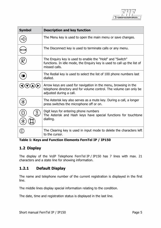
Symbol Description and key function
The Menu key is used to open the main menu or save changes.
The Disconnect key is used to terminate calls or any menu.
The Enquiry key is used to enable the "Hold" and "Switch" functions. In idle mode, the Enquiry key is used to call up the list of missed calls.
The Redial key is used to select the list of 100 phone numbers last dialled.
Arrow keys are used for navigation in the menu, browsing in the telephone directory and for volume control. The volume can only be adjusted during a call.
The Asterisk key also serves as a mute key. During a call, a longer press switches the microphone off or on.
...
Digit keys for entering phone numbers The Asterisk and Hash keys have special functions for touchtone dialling.
The Clearing key is used in input mode to delete the characters left to the cursor.
Table 1: Keys and Function Elements FernTel IP / IP150
1.2 Display
The display of the VoIP Telephone FernTel IP / IP150 has 7 lines with max. 21 characters and a state line for showing information.
1.2.1 Default Display
The name and telephone number of the current registration is displayed in the first line.
The middle lines display special information relating to the condition.
The date, time and registration status is displayed in the last line.

Page 6 Short manual FernTel IP / IP150
1 2 3
Torsten 72
06.01.06 14:40
Figure 2: Display of the VoIP Telephone FernTel IP / IP150
Position Symbol Description
1 Name (H.323 or SIP ID or nickname of the PBX configuration)
Status line; provides information on the current status of the telephone by means of the following symbols.
06.04.10 Date 14:00 Time
No connection to the gatekeeper
Connection established to the gatekeeper
Connection established to the secondary gatekeeper
Connection to the gatekeeper broken. (Both symbols are displayed in mutual change
Microphone switched off (symbol flashing)
Call diversion activated
Handset activate
Telephone locked
2
Calling number transmission locked
3 Own call number (E.164)
Called party
Calling party
Unknown number/name, unresolved number
Diverting party
Transferring party
Returning call
Call pending
4
Call on hold
Table 2: Display Contents of Default Display of the FernTel IP / IP150
Short manual FernTel IP / IP150 Page 7
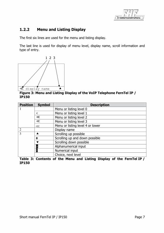
1.2.2 Menu and Listing Display
The first six lines are used for the menu and listing display.
The last line is used for display of menu level, display name, scroll information and type of entry.
1 2 3
5 display name �
Figure 3: Menu and Listing Display of the VoIP Telephone FernTel IP / IP150
Position Symbol Description Menu or listing level 0 < Menu or listing level 1 + Menu or listing level 2 5 Menu or listing level 3
1
Menu or listing level 4 or lower 2 Display name
� Scrolling up possible
Scrolling up and down possible � Scrolling down possible a Alphanumerical input 1 Numerical input
3
Choice, next level
Table 3: Contents of the Menu and Listing Display of the FernTel IP / IP150

Page 8 Short manual FernTel IP / IP150
1.3 Mounting and Installing
1.3.1 Wall Version
Fasten the telephone mount with 4 screws (2). Place the provided washers Ø 18 mm under the screw head.
Figure 4: Mounting on a Wall
Place the telephone in the upper latches (A), swing it downwards until the lower latches audibly engage (B).
Remove the keypad plate (6), and tighten the two locking screws (3) as far as they will go.
Important: This preserves the IP65 degree of protection.
The security screws may be used only mounting the telephone on a wall.
Bore
illustration (not to scale)
Short manual FernTel IP / IP150 Page 9
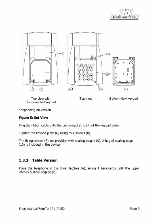
Top view with
disconnected keypad Top view Bottom view keypad
*depending on version Figure 5: Set View
Plug the ribbon cable onto the pin contact strip (7) of the keypad plate.
Tighten the keypad plate (6) using four screws (8).
The fixing screws (8) are provided with sealing plugs (10). A bag of sealing plugs (10) is included in the device.
1.3.2 Table Version
Place the telephone in the lower latches (A), swing it backwards until the upper latches audibly engage (B).

Page 10 Short manual FernTel IP / IP150
Side view Bottom view
keypad Top view
*depending on version
Figure 6: Desktop Mounting
The standard handset accommodation (for the wall version) (9) can be replaced for the table version.
After loosening the two screws (12) on the bottom of the keypad plate you can remove the standard handset accommodation.
Fasten the table version handset accommodation (11) to the keypad plate by using the included screws (12).
Plug the ribbon cable onto the pin contact strip (7) of the keypad plate.
Tighten the keypad plate (6) using four screws (8).
The fixing screws (8) are provided with sealing plugs (10). A bag of sealing plugs (10) is included in the device.
Lay the telephone cord according to the instructions, in order to prevent accidents.
1.3.3 LAN-Connections
The telephone has 2 LAN-connections
LAN-cable, used for plug into the telephone FernTel IP / IP150, have to be adapted with a connector from Phoenix contact, to preserve the IP65 degree of protection. A LAN cable connector belongs to the as-delivered condition.
The LAN-lead wire has to be connected to the connector (Position 4 in Figure 5). Die LAN lead wire has to be with PoE (Power over Ethernet). The LAN connector at the right side of the telephone can only be used for continuing the LAN, to connect for example a pc. This connector doesn’t support PoE. It is impossible to connect an

Short manual FernTel IP / IP150 Page 11
additional FernTel IP / IP150 directly. The TCP/IP data, sent to the telephone via the connector at position 4 in Figure 5, will not be redirected via the connector at the side of the telephone.
The LAN-connector of the FernTel IP / IP150 at the side has to be closed with the cover mounted to the telephone during time of no use, to preserve the IP65 degree of protection.
1.3.4 General
The receiver is equipped with a leakage field spool for coupling of hearing aids. Users of a hearing aid with inductive receiver may receive the signal from the receiver inset directly.
1.4 As-Delivered Condition
Box contents
The scope of the delivery includes: - 1 telephone - 1 telephone mount - 1 handset accommodation for the table version with 2 screws - 4 washers Ø 18 mm - 1 LAN connector from Phoenix Contact, consisting of:
o RJ sleeve housingType VS-08-T-RJ45/IP67, Art.-Nr.: 1688696 o Male insert RJ45, CAT5, 8-polig Type VS-08-ST-RJ45/IP67, Art.-Nr.:
1688573 - Short manual - Manual on CD
Accessories (optional)
- sling holder - Fly screen - LAN connector from Phoenix Contact
1.5 EMC-Directive
The device complies with the requirements of the new EMC-directive 2004/108/EC, the low voltage directive 2006/95/EC and the R&TTE directive 1999/5/EC.
The conformity with the above directives is confirmed by the CE sign.

Page 12 Short manual FernTel IP / IP150
2 Operating Manual
2.1 Operating Basics
The keys below the display ( ) of the VoIP-telephone FernTel IP / IP150 serve menu navigation and for edit field input purposes. These keys are assigned to additional functions, as explained below.
Key assignment in menu:
The function … … is performed by …
scrolling upwards Arrow key up
scrolling downwards Arrow key down
one level up Arrow key left
one level down Arrow key right
one level up with saving Menu key
one level up without saving Disconnect key , inquiry key or redial key
Key assignment in edit field:
The function … … is performed by …
scrolling right Arrow key right
scrolling left Arrow key left
Delete character in front of cursor Clearing key
The initial condition means that the telephone is in the switching state hang up. This state consists in the following situations:
a) The telephone is hang up.
b) The telephone will be hang off and then the key will be pressed.
Short manual FernTel IP / IP150 Page 13
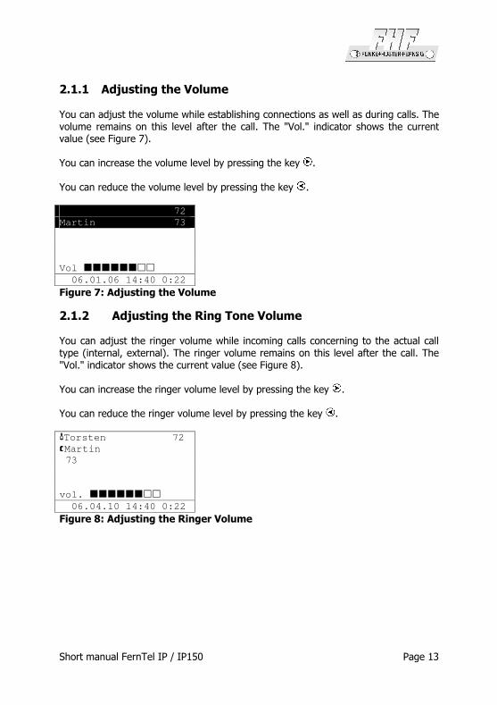
2.1.1 Adjusting the Volume
You can adjust the volume while establishing connections as well as during calls. The volume remains on this level after the call. The "Vol." indicator shows the current value (see Figure 7).
You can increase the volume level by pressing the key .
You can reduce the volume level by pressing the key .
72
Martin 73
Vol ��������
06.01.06 14:40 0:22
Figure 7: Adjusting the Volume
2.1.2 Adjusting the Ring Tone Volume
You can adjust the ringer volume while incoming calls concerning to the actual call type (internal, external). The ringer volume remains on this level after the call. The "Vol." indicator shows the current value (see Figure 8).
You can increase the ringer volume level by pressing the key .
You can reduce the ringer volume level by pressing the key .
Torsten 72
Martin
73
vol. ��������
06.04.10 14:40 0:22
Figure 8: Adjusting the Ringer Volume

Page 14 Short manual FernTel IP / IP150
2.2 Call Functions
2.2.1 Answering Calls
You receive a call and your phone rings. The name or phone number of the caller is displayed. The name or phone number of the person for whom the call is intended is also displayed. This is particularly useful in the event of multiple registrations on your telephone in order to identify the actual caller when a call is diverted to your telephone.
Call from subscriber
001723137397
for the subscriber
Torsten (72)
06.01.06 14:40 0:22
Figure 9: Answering a Call
Answering or rejecting calls:
If you would like to answer the call, lift the handset. You will be connected to the caller.
To reject the call, press the key . The phone returns to the idle state and the caller will hear an engaged tone.
2.2.2 Terminating a Call
To finish a call, put the handset back on its rest or press the key .
2.2.3 Making Calls
To call someone, you can use single or block dialling.

Short manual FernTel IP / IP150 Page 15
2.2.3.1 Single Dialling
For single dialling take the following steps:
Torsten 72
0211654321
Please dial
06.01.06 14:40 0:00
Figure 10: Direct Dialling
1. Pick up the handset.
2. Enter the phone number. In this case the VoIP telephone dials the number while it is being entered
3. At the end of the call, hang up or press key
2.2.3.2 Block Dialling
For block dialling do the following steps:
1. Pick up the handset and press the key .
2. Enter the call number and press the key or . In this mode the dialling will be executed after pressing the key respectively . During entering the call number the digits can be edited. You can move the cursor with the keys and and delete digits left to the cursor with the key .
3. Pressing the key the dialling will be executed at once.
2.2.3.3 Dialling during active Connection
During existing connections all digits (0 – 9, *, #) which are entered are transmitted as DTMF signals. Using this DTMF procedure it is possible to access menu-controlled services (e. g. answering machines, voice boxes) directly via the telephone keypad.

Page 16 Short manual FernTel IP / IP150
2.2.4 Redialling
Up to 100 of the last numbers dialled are saved automatically, together with the time and date, and can be dialled again.
01 06.02.05 11:30
Martin (Martin – 73)
02 06.02.05 11:30
Thomas (Thomas – 70)
03 06.03.05 11:29
Peter (Peter - 36)
Calls (outbound)
Figure 11: List of Recently Dialled Numbers
Dialling numbers from the redial list
1. In the initial condition, press the key . The list of the recently dialled numbers is displayed (see Figure 11).
• Success (connected/not connected). The symbol on the display indicates that there has been a call.
• The symbol on the display indicates that there has been a redirected call.
• The symbol on the display indicates that there has been a transferred call.
• The symbol on the display indicates that there has been a dialled number on a locked telephone.
• The symbol on the display indicates that there has been an automatic call.
2. Use the arrow keys to select the desired entry.
3. To start dialling, pick up the handset or use the key respectively .
Short manual FernTel IP / IP150 Page 17
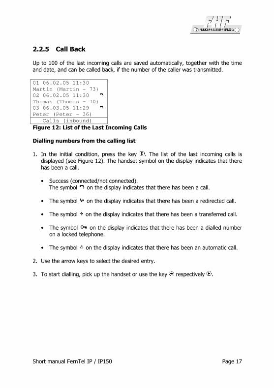
2.2.5 Call Back
Up to 100 of the last incoming calls are saved automatically, together with the time and date, and can be called back, if the number of the caller was transmitted.
01 06.02.05 11:30
Martin (Martin – 73)
02 06.02.05 11:30
Thomas (Thomas – 70)
03 06.03.05 11:29
Peter (Peter - 36)
Calls (inbound)
Figure 12: List of the Last Incoming Calls
Dialling numbers from the calling list
1. In the initial condition, press the key . The list of the last incoming calls is displayed (see Figure 12). The handset symbol on the display indicates that there has been a call.
• Success (connected/not connected). The symbol on the display indicates that there has been a call.
• The symbol on the display indicates that there has been a redirected call.
• The symbol on the display indicates that there has been a transferred call.
• The symbol on the display indicates that there has been a dialled number on a locked telephone.
• The symbol on the display indicates that there has been an automatic call.
2. Use the arrow keys to select the desired entry.
3. To start dialling, pick up the handset or use the key respectively .
Page 18 Short manual FernTel IP / IP150
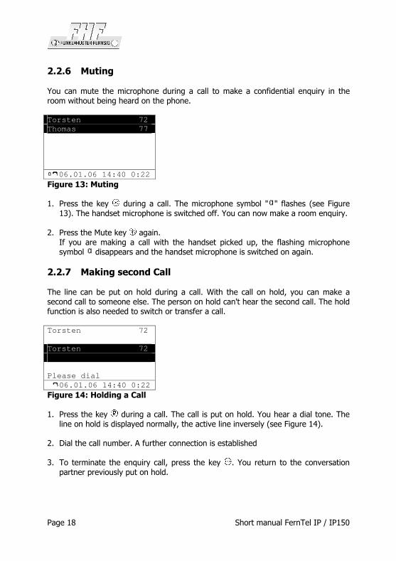
2.2.6 Muting
You can mute the microphone during a call to make a confidential enquiry in the room without being heard on the phone.
Torsten 72
Thomas 77
06.01.06 14:40 0:22
Figure 13: Muting
1. Press the key during a call. The microphone symbol " " flashes (see Figure 13). The handset microphone is switched off. You can now make a room enquiry.
2. Press the Mute key again. If you are making a call with the handset picked up, the flashing microphone symbol disappears and the handset microphone is switched on again.
2.2.7 Making second Call
The line can be put on hold during a call. With the call on hold, you can make a second call to someone else. The person on hold can't hear the second call. The hold function is also needed to switch or transfer a call.
Torsten 72
Torsten 72
Please dial
06.01.06 14:40 0:22
Figure 14: Holding a Call
1. Press the key during a call. The call is put on hold. You hear a dial tone. The line on hold is displayed normally, the active line inversely (see Figure 14).
2. Dial the call number. A further connection is established
3. To terminate the enquiry call, press the key . You return to the conversation partner previously put on hold.
Short manual FernTel IP / IP150 Page 19
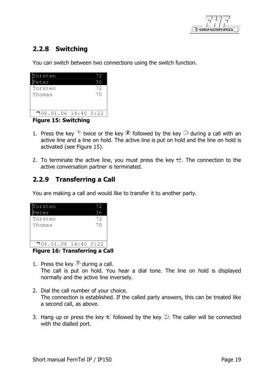
2.2.8 Switching
You can switch between two connections using the switch function.
Torsten 72
Peter 36
Torsten 72
Thomas 70
06.01.06 14:40 0:22
Figure 15: Switching
1. Press the key twice or the key followed by the key during a call with an active line and a line on hold. The active line is put on hold and the line on hold is activated (see Figure 15).
2. To terminate the active line, you must press the key . The connection to the active conversation partner is terminated.
2.2.9 Transferring a Call
You are making a call and would like to transfer it to another party.
Torsten 72
Peter 36
Torsten 72
Thomas 70
06.01.06 14:40 0:22
Figure 16: Transferring a Call
1. Press the key during a call. The call is put on hold. You hear a dial tone. The line on hold is displayed normally and the active line inversely.
2. Dial the call number of your choice. The connection is established. If the called party answers, this can be treated like a second call, as above.
3. Hang up or press the key followed by the key . The caller will be connected with the dialled port.
Page 20 Short manual FernTel IP / IP150
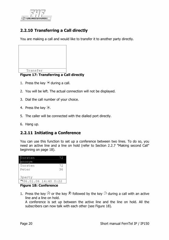
2.2.10 Transferring a Call directly
You are making a call and would like to transfer it to another party directly.
Transfer
Figure 17: Transferring a Call directly
1. Press the key during a call.
2. You will be left. The actual connection will not be displayed.
3. Dial the call number of your choice.
4. Press the key .
5. The caller will be connected with the dialled port directly.
6. Hang up.
2.2.11 Initiating a Conference
You can use this function to set up a conference between two lines. To do so, you need an active line and a line on hold (refer to Section 2.2.7 "Making second Call" beginning on page 18).
Torsten 72
anonym
Torsten 72
Peter 36
3party
06.01.06 14:40 0:22
Figure 18: Conference
1. Press the key or the key followed by the key during a call with an active line and a line on hold. A conference is set up between the active line and the line on hold. All the subscribers can now talk with each other (see Figure 18).

Short manual FernTel IP / IP150 Page 21
2. You can end the conference by pressing the key respective the key followed by the key or twice the key . If you end the conference with pressing the key or the key followed by the key , the call put on hold prior to the initiated
conference is now on hold again and the previously active call is active once again. If you end the conference with pressing the key twice, the call put on hold prior to the initiated conference is now active and the previously active call is now on hold.
To terminate the active line, you must press the key . The connection to the active conversation partner is terminated.

Subject to alterations or errors
FHF Funke+Huster Fernsig GmbH
Gewerbeallee 15-19 · D-45478 Mülheim an der RuhrPhone +49 /208 /82 68-0 · Fax +49 /208 /82 68-286
http://www.fhf.de · e-mail: [email protected]


![MG/SP: section [806] IP150 Internet Module · IP150 Internet Module Installation Manual V1.3 IP150-EI03 03/2016 Description The IP150 Internet Module is an HTTPs-supported IP communication](https://static.fdocuments.in/doc/165x107/5f32685b4e1ac873836c6e07/mgsp-section-806-ip150-internet-module-ip150-internet-module-installation-manual.jpg)