Fermi Paper Model - Fermi Gamma-ray Space Telescope
7
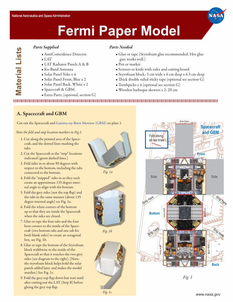
Parts Supplied • AntiCoincidence Detector • LAT • LAT Radiator Panels A & B • Ku-Band Antenna • Solar Panel Yoke x 4 • Solar Panel Front, Blue x 2 • Solar Panel Back, White x 2 • Spacecraſt & GBM • Extra Parts, (optional, section G) Cut out the Spacecraſt and Gamma-ray Burst Monitor (GBM) on plate 1. Material Lists Parts Needed • Glue or tape (Styrofoam glue recommended. Hot glue gun works well.) • Pen or marker • Scissors or knife with ruler and cutting board • Styrofoam block: 3 cm wide x 6 cm deep x 6.3 cm deep • ick double sided sticky tape (optional see section G) • Toothpicks x 4 (optional see section G) • Wooden barbeque skewers x 2: 20 cm A. Spacecraſt and GBM Snip here Snip here Snip here Snip here Spacecraft and GBM Front Bottom Side Side Back Fold along all red lines glue here glue here glue here glue here glue here Fig. 1 Fermi Paper Model National Aeronautics and Space Administration Note the fold and snip location markers in Fig.1. 1. Cut along the printed area of the Space- craſt, and the dotted lines marking the tabs. 2. Cut the Spacecraſt at the “snip” locations indicated (green dashed lines.) 3. Fold sides in to about 90 degrees with respect to the bottom, including the tabs connected to the bottom. 4. Fold the “snipped” sides in so they each create an approximate 135 degree inter- nal angle to align with the bottom. 5. Fold the grey sides (not the top flap) and the tabs in the same manner (about 135 degree internal angle) see Fig. 1a. 6. Fold the white corners of the bottom up so that they are inside the Spacecraſt when the sides are closed. 7. Glue or tape the four tabs and the four bent corners to the inside of the Space- craſt (two bottom tabs and one tab for both blank sides) to create an octagonal box, see Fig. 1b. 8. Glue or tape the bottom of the Styrofoam block widthwise to the inside of the Spacecraſt so that it touches the two grey sides (see diagram to the right). [Note: the styrofoam block helps hold the solar panels added later, and makes the model sturdier.] See Fig. 1c. 9. Fold the grey top flap down but wait until aſter cutting out the LAT (Step B) before gluing the grey top flap. Fig. 1a Fig. 1b Fig. 1c www.nasa.gov
Transcript of Fermi Paper Model - Fermi Gamma-ray Space Telescope
Parts Supplied• AntiCoincidence Detector• LAT• LAT Radiator Panels A & B• Ku-Band Antenna• Solar Panel Yoke x 4• Solar Panel Front, Blue x 2• Solar Panel Back, White x 2• Spacecraft & GBM • Extra Parts, (optional, section G)
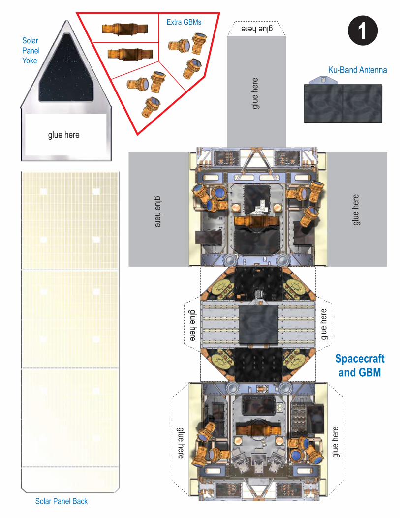
Cut out the Spacecraft and Gamma-ray Burst Monitor (GBM) on plate 1.
Mat
eria
l Lis
ts
Parts Needed• Glue or tape (Styrofoam glue recommended. Hot glue
gun works well.) • Pen or marker• Scissors or knife with ruler and cutting board• Styrofoam block: 3 cm wide x 6 cm deep x 6.3 cm deep• Thick double sided sticky tape (optional see section G)• Toothpicks x 4 (optional see section G)• Wooden barbeque skewers x 2: 20 cm
A. Spacecraft and GBM
Snip here Snip here
Snip here Snip here
Spacecraftand GBM
Front
Bottom
Side Side
Back
Fold alongall red lines
glue here
glu
e h
ere
glu
e h
ereg
lue h
ere
glu
e here
Fig. 1
Fermi Paper ModelNational Aeronautics and Space Administration
Note the fold and snip location markers in Fig.1.
1. Cut along the printed area of the Space-craft, and the dotted lines marking the tabs.
2. Cut the Spacecraft at the “snip” locations indicated (green dashed lines.)
3. Fold sides in to about 90 degrees with respect to the bottom, including the tabs connected to the bottom.
4. Fold the “snipped” sides in so they each create an approximate 135 degree inter-nal angle to align with the bottom.
5. Fold the grey sides (not the top flap) and the tabs in the same manner (about 135 degree internal angle) see Fig. 1a.
6. Fold the white corners of the bottom up so that they are inside the Spacecraft when the sides are closed.
7. Glue or tape the four tabs and the four bent corners to the inside of the Space-craft (two bottom tabs and one tab for both blank sides) to create an octagonal box, see Fig. 1b.
8. Glue or tape the bottom of the Styrofoam block widthwise to the inside of the Spacecraft so that it touches the two grey sides (see diagram to the right). [Note: the styrofoam block helps hold the solar panels added later, and makes the model sturdier.] See Fig. 1c.
9. Fold the grey top flap down but wait until after cutting out the LAT (Step B) before gluing the grey top flap.
Fig. 1a
Fig. 1b
Fig. 1c www.nasa.gov
2
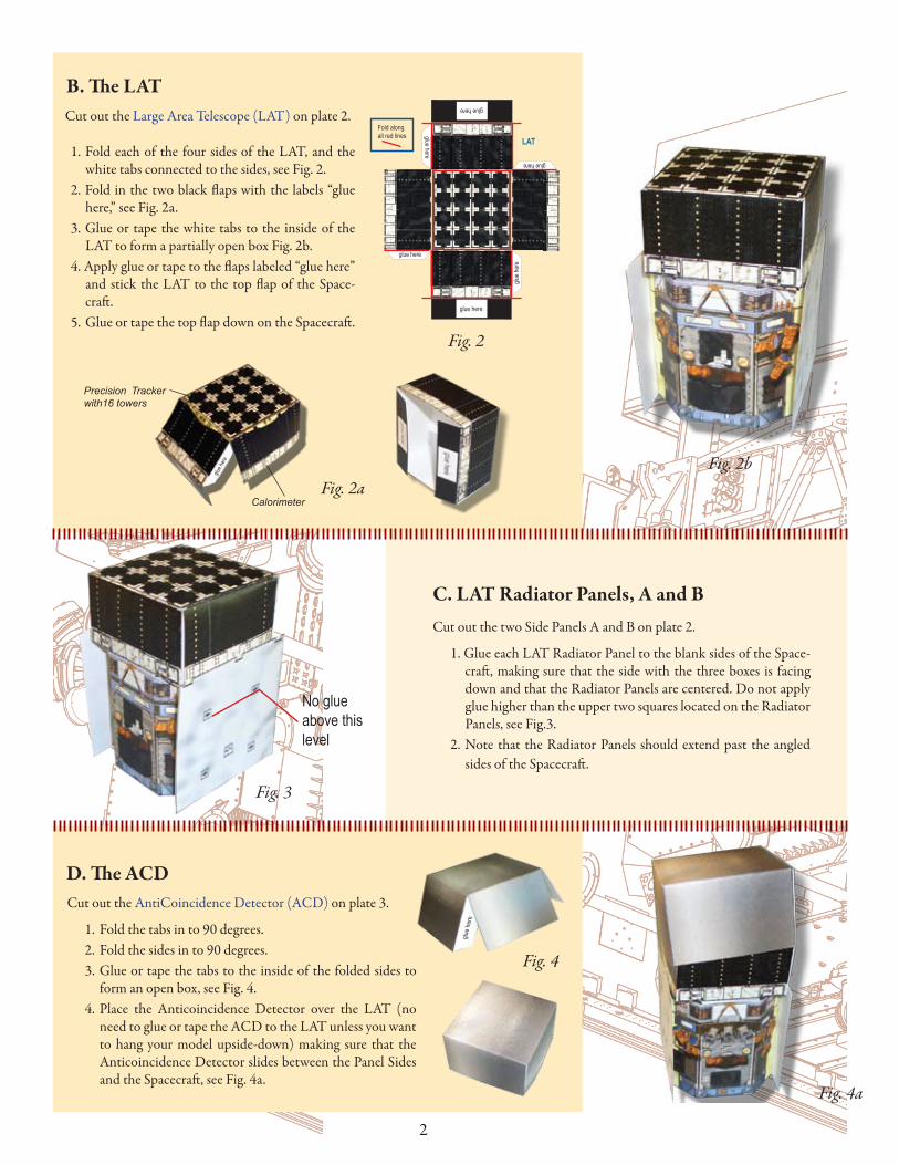
Cut out the AntiCoincidence Detector (ACD) on plate 3.
1. Fold the tabs in to 90 degrees.2. Fold the sides in to 90 degrees.3. Glue or tape the tabs to the inside of the folded sides to
form an open box, see Fig. 4.4. Place the Anticoincidence Detector over the LAT (no
need to glue or tape the ACD to the LAT unless you want to hang your model upside-down) making sure that the Anticoincidence Detector slides between the Panel Sides and the Spacecraft, see Fig. 4a.
Cut out the two Side Panels A and B on plate 2.
1. Glue each LAT Radiator Panel to the blank sides of the Space-craft, making sure that the side with the three boxes is facing down and that the Radiator Panels are centered. Do not apply glue higher than the upper two squares located on the Radiator Panels, see Fig.3.
2. Note that the Radiator Panels should extend past the angled sides of the Spacecraft.
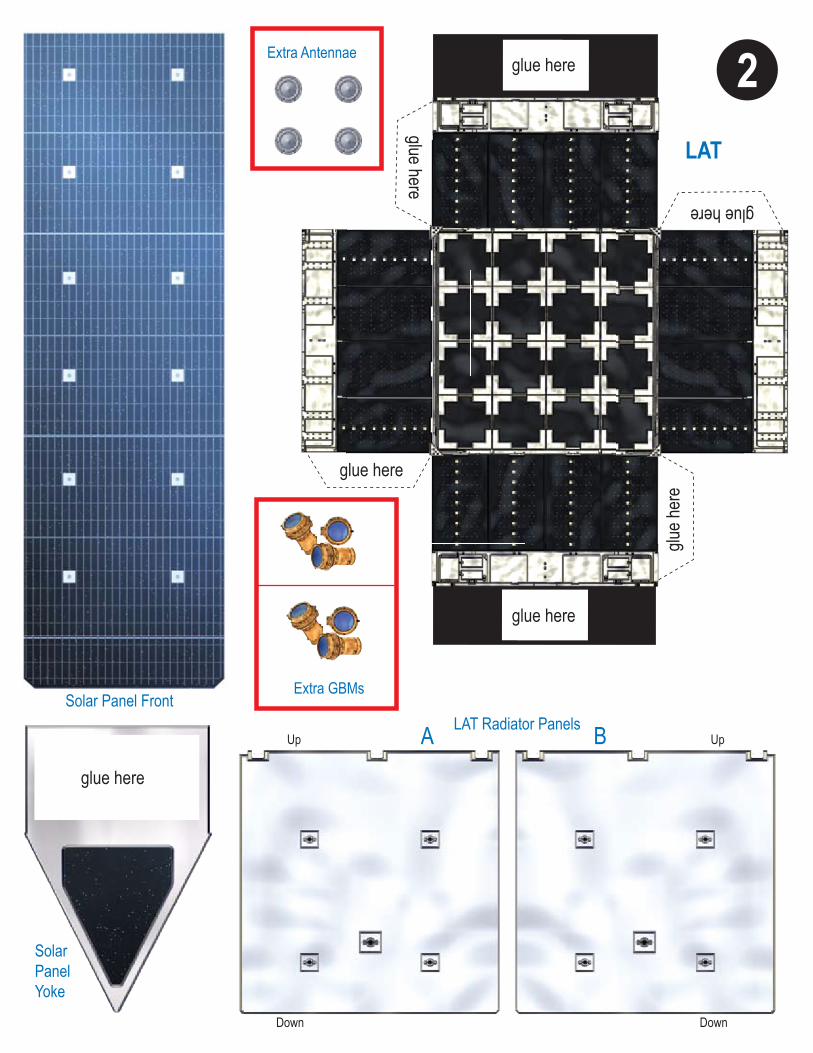
Cut out the Large Area Telescope (LAT) on plate 2.
B. The LAT
C. LAT Radiator Panels, A and B
D. The ACD
Fig. 2b
Fig. 4a
Precision Tracker with16 towers
Calorimeter
LAT
glue here
glue here
Fold alongall red lines
glue here
glue h
ere
glue here
glue here
Fig. 2a
Fig. 2
1. Fold each of the four sides of the LAT, and the white tabs connected to the sides, see Fig. 2.
2. Fold in the two black flaps with the labels “glue here,” see Fig. 2a.
3. Glue or tape the white tabs to the inside of the LAT to form a partially open box Fig. 2b.
4. Apply glue or tape to the flaps labeled “glue here” and stick the LAT to the top flap of the Space-craft.
5. Glue or tape the top flap down on the Spacecraft.
No glue above this level
Fig. 3
Fig. 4
glue h
ere
glue
here
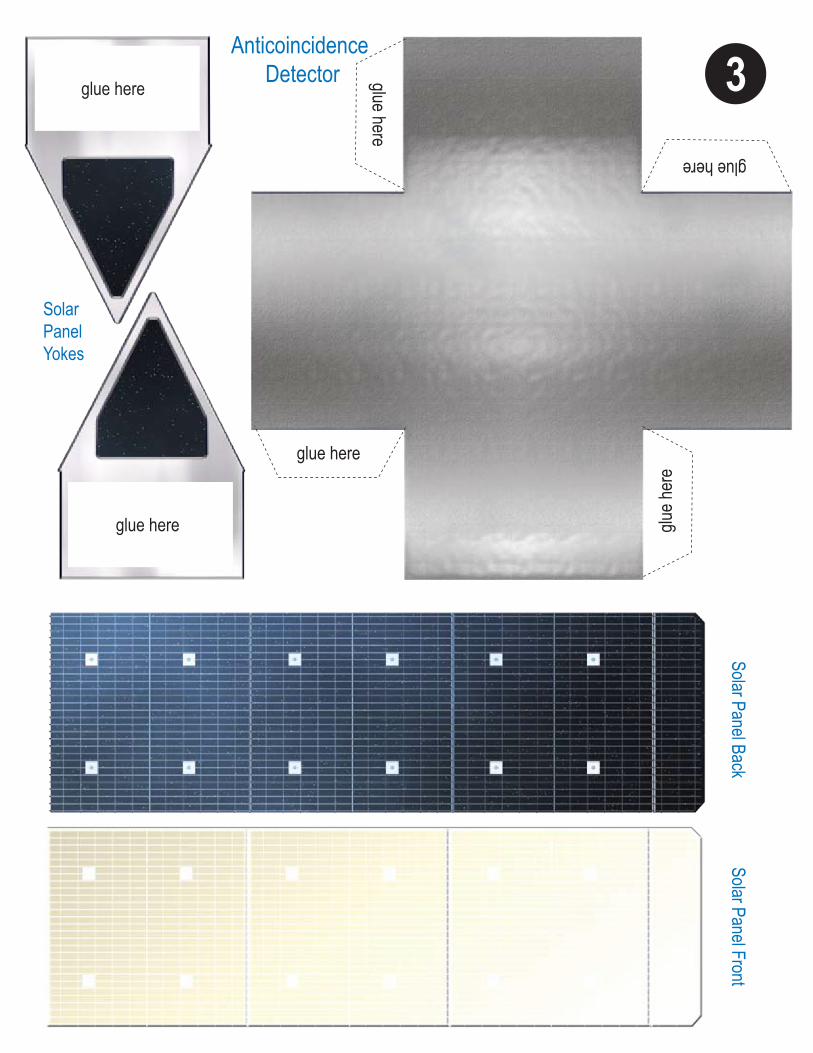
3
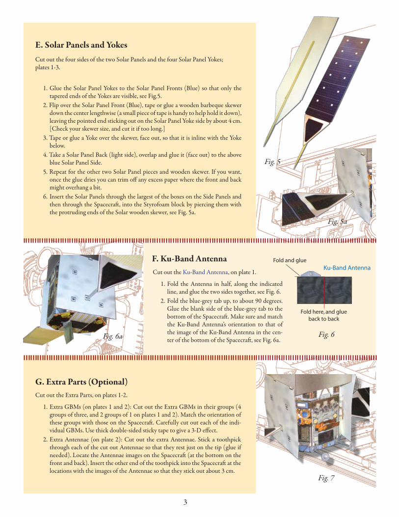
Cut out the four sides of the two Solar Panels and the four Solar Panel Yokes; plates 1-3.
1. Glue the Solar Panel Yokes to the Solar Panel Fronts (Blue) so that only the tapered ends of the Yokes are visible, see Fig.5.
2. Flip over the Solar Panel Front (Blue), tape or glue a wooden barbeque skewer down the center lengthwise (a small piece of tape is handy to help hold it down), leaving the pointed end sticking out on the Solar Panel Yoke side by about 4 cm. [Check your skewer size, and cut it if too long.]
3. Tape or glue a Yoke over the skewer, face out, so that it is inline with the Yoke below.
4. Take a Solar Panel Back (light side), overlap and glue it (face out) to the above blue Solar Panel Side.
5. Repeat for the other two Solar Panel pieces and wooden skewer. If you want, once the glue dries you can trim off any excess paper where the front and back might overhang a bit.
6. Insert the Solar Panels through the largest of the boxes on the Side Panels and then through the Spacecraft, into the Styrofoam block by piercing them with the protruding ends of the Solar wooden skewer, see Fig. 5a.
E. Solar Panels and Yokes
F. Ku-Band AntennaCut out the Ku-Band Antenna, on plate 1.
1. Fold the Antenna in half, along the indicated line, and glue the two sides together, see Fig. 6.
2. Fold the blue-grey tab up, to about 90 degrees. Glue the blank side of the blue-grey tab to the bottom of the Spacecraft. Make sure and match the Ku-Band Antenna’s orientation to that of the image of the Ku-Band Antenna in the cen-ter of the bottom of the Spacecraft, see Fig. 6a.
Ku-Band Antenna
Fold here, and glueback to back
Fold and glue
Fig. 6
G. Extra Parts (Optional)Cut out the Extra Parts, on plates 1-2.
1. Extra GBMs (on plates 1 and 2): Cut out the Extra GBMs in their groups (4 groups of three, and 2 groups of 1 on plates 1 and 2). Match the orientation of these groups with those on the Spacecraft. Carefully cut out each of the indi-vidual GBMs. Use thick double-sided sticky tape to give a 3-D effect.
2. Extra Antennae (on plate 2): Cut out the extra Antennae. Stick a toothpick through each of the cut out Antennae so that they rest just on the tip (glue if needed). Locate the Antennae images on the Spacecraft (at the bottom on the front and back). Insert the other end of the toothpick into the Spacecraft at the locations with the images of the Antennae so that they stick out about 3 cm.
Fig. 7
Fig. 5
Fig. 5a
Fig. 6a
http://fermi.sonoma.edu/materials.html
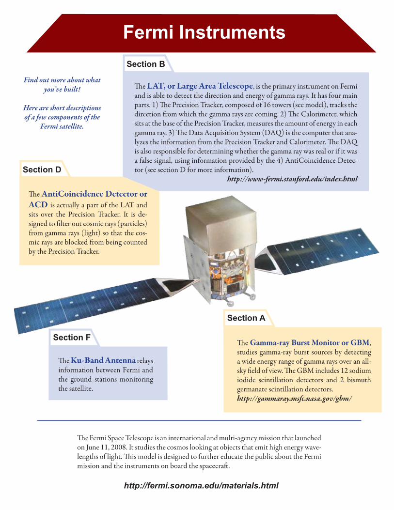
The Gamma-ray Burst Monitor or GBM, studies gamma-ray burst sources by detecting a wide energy range of gamma rays over an all-sky field of view. The GBM includes 12 sodium iodide scintillation detectors and 2 bismuth germanate scintillation detectors.http://gammaray.msfc.nasa.gov/gbm/
The LAT, or Large Area Telescope, is the primary instrument on Fermi and is able to detect the direction and energy of gamma rays. It has four main parts. 1) The Precision Tracker, composed of 16 towers (see model), tracks the direction from which the gamma rays are coming. 2) The Calorimeter, which sits at the base of the Precision Tracker, measures the amount of energy in each gamma ray. 3) The Data Acquisition System (DAQ) is the computer that ana-lyzes the information from the Precision Tracker and Calorimeter. The DAQ is also responsible for determining whether the gamma ray was real or if it was a false signal, using information provided by the 4) AntiCoincidence Detec-tor (see section D for more information).
http://www-fermi.stanford.edu/index.html
The AntiCoincidence Detector or ACD is actually a part of the LAT and sits over the Precision Tracker. It is de-signed to filter out cosmic rays (particles) from gamma rays (light) so that the cos-mic rays are blocked from being counted by the Precision Tracker.
The Ku-Band Antenna relays information between Fermi and the ground stations monitoring the satellite.
The Fermi Space Telescope is an international and multi-agency mission that launched on June 11, 2008. It studies the cosmos looking at objects that emit high energy wave-lengths of light. This model is designed to further educate the public about the Fermi mission and the instruments on board the spacecraft.
Fermi Instruments
Find out more about what you’ve built!
Here are short descriptions of a few components of the
Fermi satellite.
Section A
Section B
Section D
Section F
Ku-Band Antenna
Solar Panel Back
Spacecraftand GBM
SolarPanelYoke
Extra GBMs
glue here
1
glue h
ere
glue h
ere
glue h
ere
glue h
ere
glue here
glue here
glue here
glue here
Up
Down
Up
Down
Solar Panel FrontLAT Radiator Panels
LAT
SolarPanelYoke
Extra GBMs
Extra Antennae
A B
glue here
glue here
glue here
2
glue here
glue h
ere
glue here
glue here
Solar Panel BackSolar Panel Front
SolarPanelYokes
Anticoincidence Detectorglue here
glue here
glue here
glue h
ere
glue here
glue here
3


![QuickCost 6 - iceaaonline.com€¦ · 18 GLAST (Gamma Ray Large Area Space Telescope) [Renamed Fermi Gamma-ray Space Telescope] 19 GLORY 20 GOES I (Geostationary Operational Environmental](https://static.fdocuments.in/doc/165x107/5b7a41017f8b9a22238bc4bd/quickcost-6-18-glast-gamma-ray-large-area-space-telescope-renamed-fermi.jpg)