
FERGANA VALLEY CANAL AUTOMATION PROJECT REPORT …The team of international experts for the Fergana...
40
SWISS DEVELOPMENT CORPORATION FERGANA VALLEY CANAL AUTOMATION PROJECT REPORT OF THE THIRD MISSION OF INTERNATIONAL EXPERTS Hervé PLUSQUELLEC Pierre ROUSSET Georges FAVREAU May 10-27, 2008
Transcript of FERGANA VALLEY CANAL AUTOMATION PROJECT REPORT …The team of international experts for the Fergana...

SWISS DEVELOPMENT CORPORATION
FERGANA VALLEY CANAL AUTOMATION PROJECT
REPORT OF THE THIRD MISSION
OF INTERNATIONAL EXPERTS
Hervé PLUSQUELLEC Pierre ROUSSET
Georges FAVREAU
May 10-27, 2008

Version 2 – 26 May 2008 i
EXECUTIVE SUMMARY
The team of international experts for the Fergana Valley Canal Automation project was invited by the Swiss Development Corporation (SDC) to travel to central Asia from May 10 to 27, 2008 to review the progress of implementation of the project. From May 13 to 23, 2008, the team visited the three canal automation pilot projects in Uzbekistan, Kyrgyzstan and Tajikistan, and the BWO/Syr Darya works. An SDC mission composed of Mrs. O. Islamova and Mr. C. Morger visited the same canal areas with their own agenda during the same period. Comments were provided during meetings with each local administration in the presence of the SDC mission and SIC-ICWC staff. Prof. V. Dukhovny attended the meeting in Osh on May 19. and the transfer ceremony to the canal administration on May 20., 2008. This is the third visit of the team to the project area. The last mission took place in October 2006. At that time, the only completed component of the project was the BWO works. The installation of SCADA in the three pilot projects had not started yet. The 2006 mission found the hydro-structures in the Aravan-Akbura Canal project were ready for the installation of SCADA equipment and recommended signing the contract with SIGMA. Further rehabilitation works of the South Fergana Canal (SFC) structures were needed before proceeding with the installation of equipment. Today, there is considerable difference in the progress of implementation of the automation projects. I. BWO hydro-structures The team found that all the communication and automation equipment is in good operating conditions. All defects observed by the team during the October 2006 mission have been corrected. A Protocol was signed between all parties (SDC, SIC-ICWC, BWO/Syr Darya and SIGMA) on May 22. stating that the automation equipment is under the responsibility of BWO since January 2008 and that the communication equipment would be transferred from SIGMA to BWO by the end of 2008. The constraints to the smooth operation of the automation project are:
• The large hourly fluctuations of the flows released from upstream power plants,
• The seasonal flow pattern of the Naryn river entering Uzbekistan not reflecting the irrigation requirements,
• The frequent power cuts and
• The absence of generators causing interruption of supervisory control of the structures during power cuts.

Version 2 – 26 May 2008 ii
II. Canal Pilot Projects A. Kyrgyzstan, Aravan-Akbura Canal (AAB): The installation of the SIGMA equipment, including automation and radio communication is completed and in good working conditions. A Protocol between all parties involved was signed on May 20. for the immediate transfer of the equipment from SIGMA to AAB Canal Administration. The Protocol noted however the following observations, which are not part of SIGMA contractual obligations:
• Two out of the three gates at the head of the AAB canal can only be operated manually. The causes of the defects will be investigated and repairs done by AAB administration.
• There are frequent power cuts causing interruption of the supervisory control.
• Further training of operators by SIGMA is needed. SDC strongly recommends that AAB Administration proceeds with the repair of the two gates and purchases diesel generators, or solar panels if socially acceptable, to keep the SCADA system under operation. B. Uzbekistan, South Fergana Canal: Installation has been delayed because poor quality gate position sensors were rejected. Installation is now in progress at the head of the Shariramsai Canal, and will start at nine other structures in early June. Most structures were found ready for the installation of SIGMA equipment, with the exception at the heads of some branch canals. SIGMA expects to complete the works by end of August 2008. However it was found that the GPRS communication system adopted for BWO is not properly operating in the southern region of the Fergana valley. SIGMA is now proposing adopting a WI-FI radio system. Three solutions are under consideration for the purchase and operation of equipment and radio frequencies. A reliable voice transmission system is absolutely needed. The choice between radio UHF and cell phones depends on the capability of SFC organization to finance maintenance and operation costs. The mission supports the request formulated by SIGMA concerning the cost increase of motors and reducers. C. Tajikistan, Khoji-Bakirgan Canal: The mission found that the rehabilitation of the structures by a local contractor was not of the quality needed for the installation of sensitive automation equipment. Several reducers are poorly installed, broken or poorly welded to the gate frame. Some gate leaves have been bent because being too thin. The mission recommends not installing automation equipment until all the structures have been properly rehabilitated. Remote monitoring equipment can be installed. However it will be of little use if the gates cannot be operated to adjust the hydraulic conditions.

Version 2 – 26 May 2008 iii
III. General conclusion Overall, the team is pleased with the quality of the SCADA equipment installed and the performance of the software developed by SIGMA. The negative factors affecting the operation of this equipment, i.e. the reliability of power supply in the Fergana valley, the fluctuations of Naryn river flow and the operation of the upstream large reservoirs dictated by power supply considerations and not the irrigation requirements are international issues which are addressed at the highest level by ICWC. The team would like to stress the importance of an operation and maintenance plan for the four sub-projects. The life of the SCADA equipment is rather limited. Replacement funds have to be provided by the respective canal administrations and maintenance contracts should be arranged with private companies. Training of operators is a key factor for the success of the SCADA systems. Each canal administration shall provide extensive on-the-job training of their staff.
Version 2 – 26 May 2008 1
PROGRAM OF THE MISSION
This is the report of the third mission of International Experts recruited by SDC to provide technical assistance for the Fergana Valley Canal Automation Project. The team of SDC International Experts was composed of:
• Mr. Hervé Plusquellec, team leader and expert in the field of automation
• Mr. Pierre Rousset, senior technical expert in hydraulics
• Mr. Georges Favreau, expert in control equipment and hydraulic control
The team arrived in Tashkent on May 10., 2008. The team traveled in the Fergana Valley from May 13. to 23., 2008, starting from the Khodji Bakirgan Canal (KBC) in Tajikistan, and then moving to Uzbekistan to visit the South Fergana Canal (SFC) to assess the progress of repair works of the existing mechanical equipment and the readiness of the works for the installation of the automation and communications equipment in these two canals. The team proceeded to Kyrgyzstan on May 18. to inspect the SCADA completed works on the Aravan-Akbura canal and test the automatic control of the structures and remote monitoring. On May 20., the team proceeded to Andijan to carry out a final inspection of the BWO/Syr Darya works near Uchkurgan. An SDC team composed of Mrs. Omina Islamova and Mr. Christopher Morger traveled independently along the same itinerary to review the progress in IWRM, and creation and strengthening of Water User Associations in the three pilot canal project areas. The two teams met a number of times for preliminary reporting and discussions with SIC-ICWC and Canal Administrations. A final meeting was held on May 26. in the offices of SIC-ICWC in the presence of Mrs. Islamova, BWO staff and SIGMA Project Director. On May 17., Messrs Plusquellec and Rousset joined the SDC team to visit one of the two sites of small trans-boundary rivers proposed by SIC-ICWC for installation of a remote monitoring SCADA system (the Shakhimardansai river located south of Fergana city). A separate note was handed over to SDC team after this visit. The detailed itinerary is provided in Annex 1 and the list of persons met in Annex 2
Version 2 – 26 May 2008 2
PART I : BWO/SYR DARYA STRUCTURES, UZBEKISTAN
I. BACKGROUND The installation of the SCADA equipment for the BWO/Syr Darya structures was completed before the inspection by the team of experts during their October 2006 mission. During the wrap-up meeting in 2006, the team made several recommendations for completing SCADA system installation on the structures, and highlighted several important points for the future operation of this system. The objective of the May 2008 mission was to assess the progress made in implementing these recommendations and observations, and to review the current state of the BWO/Syr Darya SCADA system after two years of operation. In their October 2006 report, the experts recommended that commissioning of the automation and monitoring system (AMS) should only be accepted when all corrections, improvements and adjustments agreed by all parties and included in their final report have been done and properly documented. As problems were encountered in installing the data transmission system, due to the deficiency of the GPRS network, it was decided to have separate periods for experimental operation and guarantee, one for the control system itself, and another one for the data communication system. The experts highlighted the importance of maintenance and training:
• Maintenance must be well organized before the end of the one-year guarantee. The team of experts agreed that BWO contracted SIGMA on an annual basis.
• Efficient action has to be implemented by SIGMA for training operators before the system is handed over to BWO.
II. REMARKS MADE IN OCTOBER 2006 AND SITUATION AS OF MAY 2008 This section reviews the remarks made by the experts in October 2006, which were accepted by all parties:
1) Cable identification: cables were not equipped with tags allowing identifying
them for further maintenance. The team recommended installing such tags particularly on external cables.
Although it was not systematically checked that all cables in the system had been fitted with tags, many tags were observed on cables.
2) Diesel generators: at present, diesel generators are located only at Uchkurgan
barrage, BFC head works, Hakulabad divider and DP66. Procurement of diesel generators at Akhunbabaev is recommended by the team. All stand-by

Version 2 – 26 May 2008 3
generators should have enough fuel supply to cope with any emergency situation.
The canal operators do not make much use of diesel generators, and operate the gates manually in case of power cut. At DP15 the diesel generator did not have any fuel for operation.
3) Duration of PC autonomy: the autonomy of PC’s (less than one hour) is not
consistent with the autonomy of the PLC’s (6 hours). These figures were provided by SIGMA and could not be tested. Experts would have preferred to increase the autonomy of the PC’s up to 6 hours for coping with problems in starting stand-by generators, but, as mentioned in the TOR, 1 hour autonomy is enough, considering the backup energy supply. In addition, it is very easy to increase this autonomy by installing additional batteries if needed.
The UPS of PCs were found in non-operational state in many structures, resulting in PC stop just after power cuts. Due to unusually severe operating conditions (repeated power cuts, as described below), these UPS installed two to three years ago are no longer operational, and SIGMA has agreed to replace their batteries.
4) Position of level sensor downstream of Hakulabad head structure: the reading
of the sensor downstream the structure has shown erratic results during change of discharge. The reason could be that the sensor was installed at a location where fluctuating small standing waves were observed at the canal surface. It could be also due to solid deposit in the stilling well. It was agreed to clean the well in a first step and, if erratic results at low flows persisted, to change the location of the sensor.
During the tests of the system at Hakulabad divider, no error was observed on the sensor.
5) Position of level sensor downstream the Akhunbabaev headwork: the sensor is
placed close to reeds and other vegetation. The surface of water is not very smooth at this location. It was recommended to clean the bank of the canal at this location. If insufficient, the sensor could be moved slightly upstream.
Due to low water level in the Akhunbabaev canal, the reading of sensors may be impaired either by vegetation (sensor downstream head structure) or by bank (sensor upstream head structure). Small maintenance work has to be performed by BWO/Syr Darya. It was also observed that the arm of the sensor downstream the head structure is not stable. The anchoring of the sensor support should be improved (concrete base, etc.).
6) Reading of level sensors at BFC head works: the two sensors located respectively at the upstream and downstream ends of the first reach have given inconsistent measurements with sometimes H upstream > H downstream, and sometimes the opposite. SIGMA explained that this may be a problem of reference of the sensors, some of them only being adjusted to Baltic Sea Level, but in this case, the difference would be constant. It could be, also, a problem of calibration or of tuning of sensors. All parties agreed to check the level

Version 2 – 26 May 2008 4
sensors and to implement a topographical survey of all level sensors and gate sills.
This has been corrected: the two level sensors have been leveled to the Baltic Sea Level, and leveling was made on both banks.
7) General topographical survey on level sensors: for the above level sensors, and
also all level sensors of the project on the BFC, Feeder and rivers, it is recommended to perform a general topographical survey, not only inside a structure, but also between structures. This survey will be made using the closed loop technique.
In May 2008, all BWO structures have been leveled according to the Baltic Sea reference system.
8) Installation of end switches: the end switches are sensors testing the proximity
of a fixed part, located on the frame holding the drives, and a mobile part fixed on the axis of the gate. The mobile part must be carefully tightened, which may have to be checked.
No problem was observed on the end switches at all visited structures.
9) Alarm on gates: during the tests on the structures (more often on the regulating
structures than on the canal intakes), the use of the gates often raised the last alarm. This occurred randomly and no explanation could be found. As the reliable command of the gates is the cornerstone for efficient canal control, this problem must be further investigated and solved. As a conclusion of the discussion between SDC, BWO, the experts, SIC and SIGMA, it was agreed that the problem will be addressed in three successive steps:
o BWO will make their own survey, and will correct the known and found problems (e.g. wearing out of some mechanical parts, as observed in the Uchkurgan barrage or errors while manipulating the lever allowing disconnecting the engine from the gate and enabling manual operation).
o A joint inspection is made by BWO, SIC and SIGMA to find the reasons of the alarms. As it was observed that problems were more frequent on gates operated seldom, it was recommended to move all gates time to time and to permute gates under automatic mode.
o If the joint inspection was not successful, then SIGMA would propose to SDC an amendment to their contract for the installation of additional diagnosis equipment (to be defined by them) on selected gates. This may help to detect if the problem is of electrical or mechanical nature. Re-use of this equipment over the selected gates would be considered.
The gates at the Uchkurgan dam were fixed, as well as other gates showing errors on the BFC head works. No alarm on gate was observed during the tests of the structures by the team of experts.

Version 2 – 26 May 2008 5
10) Gate movement in supervisory software: signaling that a gate is in movement (e.g. blinking indicator).
This feature was satisfactorily introduced by SIGMA (black arrow pointing in the direction of gate opening, during gate movement) and was witnessed at all visited structures, except at Akhunbabaev spillway.
11) Improvement of user interface in supervisory software: for facilitating the
work of operators, BWO and SIC proposed and accepted by experts to add, during trial operation ( Protocol 21/12/06) to:
a. Provide DTS interface displaying the time elapsed since the last receipt of data in the main panel of DTS.
b. Correct errors in tabular presentation of data. c. Make on-line display of curve of current parameters in AMS for each
structure.
The time elapsed since last update of measurements is now correctly displayed and is a useful tool for the control of system operation. No errors were observed in the tabular presentation of data. Regarding display of curves, the levels are correctly displayed and were used to monitor the tests, but it is not possible to have the discharges shown as curves in all structures (BFC head works). Programming of curves displaying the key discharges at all structures would be a useful improvement.
12) Test of GPRS: GPRS was an important component of the system and must be
carefully checked before to be put into operation. All the structures in the SCADA system communicate satisfactorily with Tashkent through the GPRS network operated by the MTS company and data is acquired continuously. GPRS is a cost-effective solution in this particular case. A backup database is maintained in Uchkurgan and Kuyganyar. A communication problem still remains between these two structures, even after replacement of the radio connection by GPRS connection. The quality of signal is good, the GPRS was changed, but the problem remains. BWO/Syr Darya will check the status of their PC at Kuyganyar, which may be too old to support correctly this type of communications.
III. OTHER INSTITUTIONAL POINTS RAISED IN OCTOBER 2006 Maintenance: A contract was signed in 2005 between BWO/Syr Darya and SIGMA for the maintenance of the installed system. This contract is renewable every year. The team again insists on the fact that the life of electrical equipment is rather short, compared to civil works and gates. For example the life of most sensors is about 10 years. As a consequence, replacement of equipment has to be budgeted, in order to avoid interruption in the use of the SCADA system. The example of UPS for PCs show that repair or replacement of components of the SCADA system has to be taken into consideration even before their theoretical end of life. (10 years for batteries and UPS). In the domain of maintenance, SIGMA has introduced an interesting feature allowing easier recovery the context of a PC in case the computer has to be changed or when its

Version 2 – 26 May 2008 6
hard disk crashes. A tool was installed for creating and updating of a backup image of the hard disk, which can be saved on DVD. This image was delivered by SIGMA as the final deliverable document about programming of the PCs. More generally speaking, the standardization of technical solutions (same components and software found on the various structures) used by SIGMA is a key factor to facilitate future maintenance Training: In October 2006, training to operators was not yet performed. The experts would like to stress that the training of operators is essential for the sustainable operation of the SCADA system once it is transferred to the Canal Administration. IV. ADDITIONAL FINDINGS AND OBSERVATIONS Test of control of gates from SCADA system: At DP15, a test was performed consisting in reducing the offtake discharge from 14,3 to 13 m3/s. Another test was performed at DP66: discharge on BFC was reduced and discharge on BAC was increased of the same value (see Figure 6). Both tests gave the expected result and control of gates seems to be operating properly. The downstream control of the Feeder Canal proposed by the team between Uchkurgan and DP66 is the subject of a joint study by BWO and SIC/ICWC. The concept is to have an adjustable downstream level at Uchkurgan and DP15 to avoid encroaching on the freeboard upstream of the DP66 structure. In addition to these tests, the following points were observed:
1) Important variations of the level of Naryn river: large variations of the level of the Naryn River are observed on a daily basis (see Figure 3 and Figure 4 in Appendix). This problem was not felt with such importance in earlier years As a consequence, the automatic regulation mode of the BFC head works cannot be used when the level is too low. Moreover, water can drop to a level too low to be measured by the ultrasonic level sensor located upstream of BFC head works. In these conditions level measurements have to be performed manually.
2) Insufficient water discharge in Syr Darya river: it is not currently possible to
divert the required discharge in the Akhunbabaev canal, the Syr Darya river discharge being insufficient. The gates are fully open and the automation system is not used.
3) Poor quality of energy supply: This point is linked with the first two points.
During the inspections of BFC head works, Hakulabad divider (DP15), DP66 and Akhunbabaev head works, interruption of power supply from the grid were observed. It was reported that these interruptions are very frequent this year because of very low storage in Toktogul reservoir. Letters were written by BWO to their electricity provider and to the Ministry, resulting in less power cuts, but these cuts are still too frequent. It is recommended to procure small diesel generators to supply the operation of PLCs, computers, sensors and communications. Automatic start of these generators should be made possible on detection of power cuts.

Version 2 – 26 May 2008 7
4) Improvement of level sensor recording: After loss of energy supply and
restoration, the measurements of the ultrasonic level sensor show an erroneous peak. SIGMA introduced (except at Akhunbabaev) a time-out of 5 minutes after the sensor is put back in operation, which allows suppressing these erroneous values.
5) Alarm on energy loss: A useful improvement was introduced by SIGMA: on
power cuts, and before the UPS of the PLC fails, an alarm is sent to Tashkent, which allows setting apart communication gaps due to the GPRS operator from those due to lack of energy.
V. CONCLUSIONS ON THE BWO/SYR DARYA SCADA SYSTEM The equipment at the visited structures is in good operating conditions and only requires minor maintenance work (painting, repair of electrical connection boxes). The remarks by the team in October 2006 were taken into consideration in their great majority. Useful improvements were made at the initiative of SIGMA and BWO, such as filtering of level sensor reading and emission of alarm to Tashkent in case of power loss. This is an indication that system improvements were not limited to the remarks made in 2006. Based on the satisfactory work performed by SIGMA on the BWO/Syr Darya system, it was decided:
• to close the guarantee period and to proceed with the hand-over of the SCADA control system from SIGMA to BWO/Syr Darya, and
• to accept January 2008 as starting date of the one-year guarantee period for the data communication system.
A Protocol based on these two points was signed by all involved parties in the BFC head structures on May 22, 2008. The twin problems of energy supply and highly variable water level in Naryn River are felt with an acute importance this year. For successful use of the control system of BWO structures, it is essential to alleviate these problems. The seasonal operation of Toktogul reservoir is a highly complex interstate issue addressed by ICWC. However it should be possible to develop a solution to release a more stable daily discharge, using the capacity of the cascade of power projects downstream of Toktogul, especially at Kurupsai which has a re-regulating capacity of over one billion m3. VI. POSSIBLE EXTENSION OF THE SCADA SYSTEM TO OTHER BWO/SYR DARYA STRUCTURES BWO/Syr Darya would like to further extend the remote monitoring in the Naryn system to improve its water balance and operation. A list of seventeen sites was

Version 2 – 26 May 2008 8
jointly established by the BWO/Syr Darya organization and SIC/ICWC. Automation of structures is not considered. Four of these sites were visited by the consultants:
• Gauging station on the Naryn river, downstream of the BFC head works:
• Offtakes to branch canals (respectively 7 and 10 m3/s) on the left hand side bank of the BFC canal
• Control structure on the Feeder Canal just upstream the confluence with BFC No copy of the preliminary report was submitted to the team. All these sites were reported to have energy supply installed or available nearby, and all are located close structures with BWO/Syr Darya local staff. For these reasons, and because of availability of the GPRS services, the technical context of this extension seems favorable. A detailed study should be prepared by BWO/Syr Darya for submission to SDC. This study shall include:
• a geographic map of all proposed points,
• the detailed justification of each site,
• cost estimates for installation of the system at each site,
• description of the availability of energy and staff.

9
VI - APPENDIX: FIGURES AND CHARTS
Figure 1: Snapshot of levels and discharges in the BWO/Syr Darya structures on May 21, 2008
For each structure, the time below the measurements indicates the time elapsed since last update (Kuyganyar in red has permanent communication problems). This chart illustrates the low values of discharges in the whole system.
Figure 2:Location of the level sensors at BFC head works on Naryn River

10
Figure 3:Variations of the level at BFC head works on Naryn River over a 2-day period
The chart shows the river level upstream of the structure (green), the level downstream the structure (red). The river bed is at elevation 500. Every day, an important decrease of level is observed early morning (see detail below), and also sometimes in the afternoon.
Figure 4:Variations of the level at BFC head works on Naryn River – detail of previous chart.
The chart shows the river level upstream of the structure (dark red, above), the level downstream the structure (pink, below).

11
Figure 5:Location of discharges changed during test at DP66
Figure 6: Results of discharge test at DP66
The chart shows the discharge to the Big Fergana Canal (green, above), the discharge in the Big Andijan Canal (red, below).

12
PART II: PILOT CANALS
The team of experts visited the three canal automation pilot projects in Uzbekistan, Kyrgyzstan and Tajikistan from May 13. to May 20., as detailed in Annex I. Out of the three pilot canals, only one, the Aravan-Akbura Canal (AAB) in Kyrgyzstan was ready for testing of SCADA equipment. The installation works on the SFC have started on only one structure at the Kampiravvat head works. The level of rehabilitation of the water control structures in Khoji-Bakirgan was found inadequate for starting the installation of SCADA equipment. The three pilot canals would be operated under the upstream control strategy. The flows at all the canals diverting water from the hydro-structures included in the project would be automatically controlled to maintain a stable target flow to the users. The gates on cross regulators will provide automatic upstream water level control. It is also important to note that automation provided by the project is limited to control of water level or flows at key structures. The SCADA does not provide an automatic management of the entire canal system, such as the interaction between hydro-structures. The SCADA only provides a real time information tool to a control centre allowing the Canal Administrations to take best management decisions.

13
A. SOUTH FERGANA CANAL The goal of the mission of the experts was to review the progress of the rehabilitation of the structures and installation of the SCADA system by SIGMA. The original program of the mission provided a full day to inspect and test the automation works at Kampiravvat structure, since it was expected that SIGMA would have completed the installation of the equipment. When the mission was informed that the works were not finished, the program was revised to complete the visit of the 10 hydro-structures in two days on May 15. and 16. The only site where SIGMA has started working was the Kampiravvat structure. The following observations have been made during the inspection of the water works on the SFC. In the framework of their ongoing contract for SCADA installation, SIGMA prepared with SIC-ICWC a document regarding:
• change of the communication system, part of the SCADA system,. comprising a data network and a voice network,
• update of the prices of the reducers and motors,
• update in the wages of SFC staff.
The experts studied the first two technical points referred above. I. OBSERVATIONS ON THE HYDRO STRUCTURES
1. Kampiravvat water works The installation of SCADA equipment was in progress during the visit. The progress is the following:
• Gate control boxes have been installed
• Wiring to the motors has been started (cables installed, but not connected yet)
• The gate position sensors were returned by SIGMA to their factory, because of poor quality.
It is expected that the work on Kampiravvat will be completed by SIGMA by mid-June. The missing elements were the gate position sensors, the PLCs and their cabinets, the computers and supervisory software and the wiring to the motors. The Andijan power plant is operated on the basis of irrigation requirements on a continuous basis. i.e. there is no production of peak energy. The present operation consists in controlling the discharges in the three irrigation canals through hydro-posts. The power plant management organization checks the releases to irrigation canals on a hydro-post located about one kilometer upstream from the dividing structure.
2. Intake of SFC

14
The intake of the SFC consists of a weir without any control gate. The Shariramsai intake is equipped of three gates to be used for flow control.
3. Akbura water works at DP 36: crossing of Akbura River The two siphons under the river are not gated. The aqueduct over the river drains into a very short pool with two gates supplying a small irrigation canal and two other gates connecting with SFC. The mission identified a number of defects with the reducers of these four small gates.
4. Aravansai water works at DP 261: crossing of Aravan river
The three siphons under the river bed are not gated. The only gate at that site is an escape with will be equipped with a level emergency device.
5. Khamza water works at DP 360: diversion of Karkidon Canal That structure is the most important one of the SFC, as it controls the diversion of water to the Karkidon reservoir. The flow to the SFC canal will be adjusted to the target value and the gate at the head of Karkidon canal will provide automatic level control.
6. Karkidon reservoir The 70 m high Karkidon dam creating a 212 million m3 reservoir plays an important role for the operation of the 120-km long SFC canal as a compensation reservoir. The target flow in the downstream section of SFC is controlled both at Khamza structure and at Karkidon reservoir. The hollow jet gates were releasing about 5 m3/s on the day of the visit. The project provides monitoring of the reservoir level and positions of the hollow jet gates and bulk gates.
7. Palvantash water works at DP 570 That structure is located at a point where the SFC is divided into two branch canals which drop about 20 m before joining again into a single canal. Only the left branch is equipped of three gates. Electric motors have been installed on these gates as well as at the head of the Mayarik branch canal where some defects were observed on reducers.
8. Tolmazar water works at DP 670 This structure diverts water to the Kuasai canal through a radial gate. The regulator on the SFC consists of two bays, with only one equipped of a radial gate.
9. Beshalishai water works (DP 950) That structure located at the crossing of the SFC with the Beshalishai River is the most complicated one on the SFC. It makes possible to transfer water between SFC and the river and the opposite. A diversion structure of oval shape located on the river about 200 m consisting of 8 flat gates is located just downstream of the crossing with SFC to supply water to canals on both sides. All the 18 gates of this complex have

15
been motorized. Not all of the 8 gates of the diversion structure are in good conditions. These gates will not be automated, but equipped only for local control. Two gates on the SFC will automatically control the level upstream of the diversion structure in the river section. Two other gates will control the upstream level of SFC.
10. Margilansai water works (DP 1034) That simple structure consists of a 3-bay regulator of which only two are equipped of motorized gates, and one bay is ungated at the head of the Margilansai canal. The two gates of the cross regulator are not in good operating conditions and apparently rarely operated. II. DATA COMMUNICATION SYSTEM Unlike the BWO/Syr Darya system, the GPRS data communication system cannot be adopted for SFC, because telecommunication operators do not provide such services in the southern region of Fergana valley. A comparable WI-FI solution, allowing a real networking architecture, was studied by SIGMA which submitted a technical and financial proposal to SDC through SIC-ICWC. The proposal is based on information obtained by the SARKOR Company, specialized in these technologies, and in possession of a license to operate equipment in entire Uzbekistan, as described in the proposal. This proposal does not include all information for decision making. Additional details were asked from SIGMA. The proposal relies on WI-FI equipment operating in the 2.4 GHz range. Such equipment allows, with proper programming and installed devices, to install a real network where sites can be connected in an event-based mode (which offers a better system than a classical radio system where stations are polled one after another for information). The topology of the network would be of star type, the center of which would be hosted by a telecommunication tower on an elevated place south of Andijan, and acting as a hub/switch for the whole SFC system. This site would then send the data from the structures to the planned SCADA center in Quva (and in the opposite direction can send discharge set points to the structures or dispatchers). The complete list of structures and detailed map of the system was asked by the team to SIGMA. This company already modeled the most difficult links using IRDAS Imaging software, and their proposal takes into account the results (some repeaters are foreseen for distant sites). Three main options, technically identical, are possible to install and operate the data transmission system, depending on how the equipment is procured and how the frequencies are operated: Solution 1: the equipment is rented from SARKOR Company, the design study is performed by the SARKOR Company, and the frequency is rented from SARKOR using their license. Solution 2: the equipment is purchased by SFC from SARKOR Company and the other two points are unchanged: the design study is performed by the SARKOR Company, and the frequency is rented from SARKOR using their license.
16
Solution 3: the equipment is purchased by SFC from SARKOR Company or another provider, SARKOR performs a more detailed study to prepare the request for license, and the license for frequency is requested from the administration by SFC. This will be a license for a specific region and project (which is not an obstacle for future projects). Solution 1 Solution 2 Solution 3
Equipment Rented from SARKOR
Bought by SFC from SARKOR
Bought by SFC from SARKOR
or other
Design Performed by SARKOR
Performed by SARKOR
Detailed design in order to get government
approval
Frequency Rented from SARKOR
Rented from SARKOR
Allocated by government for
project and region
Investment cost (USD) 91 000 To be provided
by SIGMA To be provided
by SIGMA
Operation cost (USD/year) 32 700 To be provided
by SIGMA To be provided
by SIGMA
Maintenance cost (USD))
To be provided by SIGMA
To be provided by SIGMA
To be provided by SIGMA
The main characteristics of each solution are the following: Solution 1: this solution minimizes the investment cost, as no equipment has to be bought by SFC. It is also the fastest solution that can be put in place, as no license needs be obtained from the administration. It is also the solution that will most likely have the highest operational costs. Operation and maintenance are performed by SARKOR. SIGMA was asked to provide a quotation for this solution, including investment, operation and maintenance. Solution 2: in this solution, the operation cost will be reduced, as the equipment is not rented, but the investment costs increase. As solution 1, it is a solution that can be put in place quickly. SIGMA was also asked to provide a quotation for this solution. This quotation will have to include the cost of maintenance by SARKOR. Solution 3: is the solution where investment costs will be comparable to solution 2 (possibly slightly higher, as the study by SARKOR must be more detailed in order to justify all data links). The operation costs will be very low (energy consumption), but some cost for maintenance has to be foreseen. The investment cost of such a solution is estimated by SIGMA to 91 000 USD. SIGMA will have to provide the operation and maintenance costs.

17
In fact, a fourth solution can be envisaged, consisting of installing the system and operating it in a first time as in solution 2, and simultaneously request the frequency license for SFC as in solution 3. Therefore, even if administrative procedures take a long time, it will be possible to use the data transmission system quickly. One possible problem in this solution would be that the administration may refuse to grant a license a posteriori on a system that was put into operation without their control and approval. No spare equipment is provided for the data transmission system. Spare equipment is critical to ensure continuity of service at the hub station. Indeed, if equipment at this station fails, it must be put back into operation quickly to restore communications in the whole system. The system installed at each site shall be able to locally store all data to be sent in case of problem at the hub, and to send them when connection is restored. A complete station (WI-FI devices, cables, antenna and all required hardware and software) shall be added to the BOQ. III. VOICE COMMUNICATION SYSTEM A voice communication system is required to connect observers and their dispatcher station. A total of 10 dispatcher stations and 20 mobile users are estimated by SIGMA/SIC ICWC. Solution 1: the proposed system is a conventional system based on radio equipment operating in the 140-166 MHz range. Spare equipment has to be supplied. Solution 2: the team made the remark that a solution based on mobile phones was not envisaged. According to information obtained during the site visits, coverage of the region, although not complete, is satisfactory. Replacing a telephone in case of equipment failure or loss will be simple, as well as adding new telephones in the system, and no spare equipment is required. The characteristics of the two solutions are the following: Solution 1: this solution has high investment costs, estimated by SIGMA to 55 000 USD. The operation costs are very low and the maintenance cost (including renewal of equipment), based on a classical ratio of 8% is 3 700 USD per year. Solution 2: the solution has a low investment cost of 1 500 USD (system with 30 telephones, each costing 50 USD), a low maintenance cost of 120 USD per year (8%). The main costs are operation costs. Based on a communication time of 30 minutes per day (3 times 10 minutes at each control), a communication cost of 0,03 USD/min and a monthly fee of 10 USD, the yearly operation cost is 13 500 USD. It was also mentioned that staff might use telephone for personal use. IV. UPDATE OF THE PRICE OF REDUCERS AND MOTORS

18
The terms of reference used for the computation of SIGMA contact are based on prices obtained in 2004. Between 2004 and 2008 the costs for purchasing these equipments have escalated, mainly due to the increase in cost of irons and non-ferrous metals. The contract did not provide any price revision. SIGMA requested an update of these four-year old prices. As good quality motors and reducers are the basis for a successful introduction of SCADA system, special attention must be paid to this activity. V. CONCLUSIONS ON THE SOUTH FERGANA SCADA SYSTEM Site installation The mission reiterates the earlier recommendation that SIGMA proceeds with the installation of SCADA equipment. However all the gates and accessories will have to be tested before installing SCADA equipment. Motors and reducers will have to be changed or repaired as necessary. Data transmission system SIGMA shall provide the cost estimates for all three solutions. The mission recommends adopting solution 2 or 3. The selection of the solution will depend on the capacity of funding the operation and maintenance costs by the SFC administration in the future. Voice transmission system The voice transmission system is absolutely required. Two technical solutions are possible, the cell phones being more flexible. The final decision will be based on the possibility by SFC to bear operational costs. The opinion of the team is that the cell phone solution would be preferable. Update of costs of motors and reducers The Consultants support SIGMA request for the revision of the prices of motors and reducers.
19
B. ARAVAN-AKBURA CANAL
I. PROJECT DESCRIPTION Aravan-Akbura Canal (AABC) takes water from the Akbura River supplied by the Papan Dam and irrigates Karasu and Aravan rayons in the Oblast of Osh. The total command area is 9 248 ha of which 6 243 ha are in the rayon of Karasu and 3 005 ha in the rayon of Aravan. The automation project includes four hydraulic structures and ten gauging stations or hydro-posts:
• The diversion dam on the Akbura River with two large radial gates for the spillway (control of upstream level in the river), three sluice gates for Aravan-Akbura Canal (control of discharge) and two other sluice gates for supplying water to the Right Main Canal (control of discharge). The two hydro-posts at the head of both canals are also included in the SCADA system.
• The hydraulic structures at DP 70 which comprise two sluice gates (only one is motorized) operating as a cross regulator on the AABC associated with a hydro-post and the “Bochkarev gate”, an old automatic mechanical gate which has been also motorized. This latter has two functions: (i) supplying water to Kayirma and Yangi canals, (ii) spilling excess water to Akbura River when needed through Kayirma-Yangi structure (maintaining a constant upstream level).
• Kayirma-Yangi structure comprising three automated gates: (i) the escape to Akbura River by a motorized “Bochkarev gate” (constant upstream level), (ii) the headwork of Yangi canal (control of discharge), (iii) the headwork of Kayirma canal (control of discharge). The latter two are both associated with hydro-posts.
• Structure at DP 135 of Kayirma canal comprising two parts: (i) a cross regulator upstream of a drop on Kayirma canal with two gates (control of upstream water level), (ii) headwork of Kura canal with one gate (control of discharge). Both are associated with hydro-posts.
• Two balancing gauging hydro-posts at DP 215 and DP 298 of AABC; these hydro-post are included in the SCADA system.

20
II. ORGANIZATION OF WATER MANAGEMENT OF AABC There are two levels of water management:
• The Master Control Station (MCS), located at DP 70. It receives instructions from AABC Administration in Osh and sends back information. It also supervises the overall operation of the canal, processes data received from the lower level operators, and dispatches operational instructions to them.
• The Local Control Stations (LCS) located along the canal. They supervise the operation of one automated structure, input the various set points (water levels and flow), dispatch instructions and receive data from observers and inform MCS. The observers play an important role in the water management: they adjust the flow at the irrigation off takes to the scheduled value; they read the actual discharge supplied to the farms 4 times per day during the growing period, they collect the irrigation demands of farmers and they report all this information to the LCS.
III. DATA AND VOICE COMMUNICATION NETWORKS The communication network comprises two parts: (i) data transmission from and to measurement and automation devices and between MCS and LCS, (ii) voice communication between observers and LCS. Design of communication network has evolved since the beginning; initially it was planned to use GPRS, but following the problems encountered for BWO project, it was decided to use VHF radio with 4 frequencies and 2 repeaters (2 for data transmission and 2 for voice communication), and finally two radio systems were installed: one using one frequency and no repeater for voice and another for data using one frequency and one repeater. IV. SCADA AND WATER MANAGEMENT SOFTWARE The SCADA software is similar to the one installed at BWO: all measurements data and information on status and alarms are displayed and stored on PC’s of LCS and set points are input there and then sent to automation devices. Only main measurements such as water level and discharge are sent to the MCS. Two programs for water management have been developed and installed by SIC at MCS and LCS, they allow calculating the seasonal irrigation schedule according to the cropping pattern and the expected water resource, the irrigation schedule for the next decade according to farmers demand and water available at the dam, input the actual daily water volume delivered at each off take and compare to the scheduled one.

21
V. IMPLEMENTATION OF SCADA The SCADA system was installed by SIGMA; the work started in May 2007 and was completed by December 2007. Due to water shortage, it was not put into operation before April 2008. Thus, when experts visited the project it had been working for only three weeks. The task of SIGMA included the training of ten operators which was done in Tashkent. VI. VISIT OF THE PROJECT AND FINDINGS OF THE EXPERTS The international experts visited the project from May18. to 20., 2008. A general presentation of the project was done at the office of AABC Administration in Osh and then, all stations of the system were visited except the hydro-post at DP 215. In general, it was observed that all structures and equipments were in excellent condition with a few exceptions as reported below. In the MCS, at DP 70, the various features of the SCADA and of the water management software were presented by AABC employees and SIC programmers. As in the same office, there is also a LCS controlling the structure, the presentation included the LCS software as well. At DP 135 of Kayirma canal, several tests of structures automation were performed either on the upstream level control or on the discharge control of the headwork of Kura canal. They consisted in changing the set points and observing the reaction of the automatic gates and the result obtained on the controlled parameters. It was observed that the duration of the transitory period between two stable regimes did not exceed 20 minutes; stability of automatic process was satisfactory and accuracy of adjustment was better than 5 %, as requested in the TOR. In all automated structures, motorization of gates was working, except at the head work of AABC on Akbura River where two out of three of gates supplying the AABC were not working (see Figure 8). It was also noticed that many power cuts occurred during the visit. The duration of some of these cuts were relatively long and exceeded the autonomy of the UPS (backup power supply by batteries) serving the automation and measuring devices. The worst consequence is the loss of measurements in some cases. Operation of gates can be done manually during any power cut because all automatic structures are staffed. This situation is mainly due to the water shortage of water and consequently the shortage of electrical production in Kyrgyzstan. At the start of the project, such problems were not expected, and no backup generators were provided. Most of demonstrations of practical utilization of the PC’s were done by SIGMA employees or SIC programmers. Operators of AABC seemed not to be very confident and seemed slow in operating PC’s and running the SCADA and water management software. This can be easily understood because these new technologies represent a big change for them and utilization of the system was

22
limited to three weeks which is rather short for practical on-the-job training. Additional assistance from SIC and SIGMA is still necessary and a new training session could be organized. VII. RECOMMENDATIONS OF EXPERTS The recommendations of the experts are the following:
• The two gates of AABC head work which are not working must be repaired, and actions for avoiding such default have to be taken. Regular maintenance of all equipments must be done. The best solution is to have a contract with a private company, as it was done with SIGMA on BWO structures.
• Actions have to be taken for avoiding loss of data in case of power cut. It is recommended to install a backup power supply, either by diesel generator or by solar panels and batteries; only measurements and data transmission have to be backed up and require limited power.
• It is recommended to extend the assistance of SIC and SIGMA to AABC to provide an efficient on-the-job training to the operators; an additional session of practical training could also be organized on site as quickly as possible.

23
VIII - APPENDIX: FIGURES AND CHARTS
Figure 7 AABC General scheme

24
Figure 8 Head Work Screen Display
The two dotted circles indicate the gates which can only be operated manually.
Figure 9 Head work- gate automation screen display

25
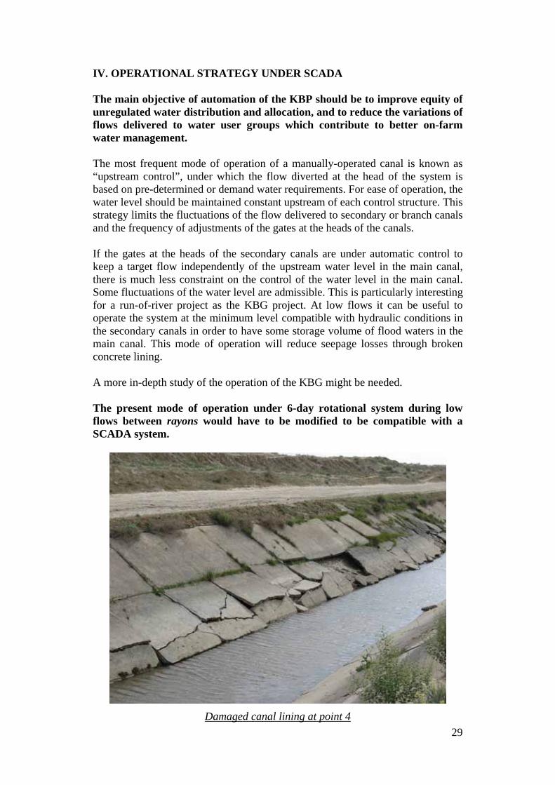
C. KHOJI-BAKIRGAN CANAL I. BACKGROUND A short description of the project is provided, because it is the first visit by the team to this canal. 1.1 Project Description The Khoji Bakirgan Irrigation project (KBP) is a run-of-river irrigation scheme diverting water from the unregulated river of the same name to irrigate about 8 275 ha. The 22.8 km long main canal, also known as Gulyakandoz, has a design capacity of 32 m3/s, which is at least 2.5 times above the peak irrigation requirements. The area served is located in two rayons, Gafurov and Rasulov, of respectively 3 267 and 4 462 ha. The KBP was built in the 1950’s. However it was reported that a traditional earth canal was built by the villagers of Gulyakandoz about one hundred years ago. The diversion dam built in 1953 is located at the border of Tajikistan with Kyrgyzstan. Since there is no diversion between this dam and the Syr Darya river, all the incoming flow is released into the KBP. Three out of the four radial gates are opened during flood periods. However, because of the time required to handle these gates through an antiquated system, part of the flood flow has to be accommodated into the KBP, which explains the over-sizing of the KBP canal. Typical hydrographs show that the average monthly flows are low during the early months of the cultivation season from April to mid-June, and then increase due to snowmelt at high elevations. There is shortage of irrigation water during the early irrigation season and then excess availability of water. In 2001, a 6-day rotational mode of operation between rayons was introduced during the months of low flow, in which water is delivered to each rayon for a 3-day period. A secondary rotational system is organized within the secondary canals of each rayon. Because of the absence or non-functioning of most gates, the downstream part of the canal is drained during each rotation, instead of being kept full as a reservoir, even when that section is not delivering water. Recorded data for the year 2005 indicate that there is some inequity of water distribution between rayons: the two rayons received 63 and 47 million m3 respectively, which is equivalent to 17,200 m3 and 10,200 m3 per hectare. The main canal was concrete-lined over its entire length, with the exception of the upstream 3 km. Considerable damages to canal lining were observed during the field visit, mostly on the left hand side, which is characterized by a bank at a higher elevation. The damages to the concrete panels, such as sliding and horizontal breaks are typical of the damages caused by cycles of frost and thawing. The repetitive cycles of filling and draining of canals due to the

26
rotational operation causing rapid drawdown and back-pressure have also contributed to the situation. 1.2 The Canal Automation Project in Tajikistan When the Fergana Valley Canal Automation Project was initiated by SIC-ICWC with the assistance of SDC in 2004, the KBP canal was selected as the pilot project in Tajikistan. After visits by SIC-ICWC experts, it was decided that the interventions would be limited to remote monitoring because of the poor condition of the control infrastructure. Remote monitoring is the simplest form of a SCADA system. It was suitable for a run-of-river system with unregulated water resources. KBP is the only one of the three pilot projects not to benefit from regulated resources, as it is the case for the other two canal pilot automation canals in Uzbekistan and Kyrgyzstan. About two years later, the financing for the rehabilitation of the KBP was ensured through another donor. This included two main contacts:
• rehabilitation of concrete lining by the contractor PMK,
• rehabilitation of gates, including civil works, hydro-mechanical equipment, reducers and motors, and electrical power supply by contractor Gayur.
It was then agreed between all parties that the KBP SCADA project would be upgraded to the next level including automation of key control structures in addition to remote monitoring. It was well stressed by SDC and SIC-ICWC that the rehabilitation of gates has to be completed in a satisfactory manner before proceeding with the installation of automation equipment. The studies by SIC provided that a control center located in Chkalovsk would receive measurements from the main six sites (see list below). Instructions would be sent to dispatchers who would send commands to the gates. The studies in progress provide using a radio network (with repeater for the head structure) comparable to the one installed in the Aravan-Akbura project. The main objective of the May 2008 SDC mission of experts was to assess the progress with the rehabilitation and the suitability of the hydro-mechanical and electrical equipment for the installation of the SCADA equipment by SIGMA contractor. II. INSPECTION OF THE CONTROL STRUCTURES AND ASSESSMENT OF READINESS FOR INSTALLATION OF SCADA EQUIPMENT The six structures to be automated were all visited by the team of experts and the staff of the Khoji Bakirgan Canal Administration (KBCA) on May 13. and 14., 2008:
• point 1: KBC head works on Khoji Bakirgan river,
• point 2 at DP 24,

27
• point 3 at DP 33,
• point 4 at DP 61,
• point 5 at DP 100,
• point 6 : Gorodskoy waterworks on Kostakoz canal. For reasons of time and operating conditions of the canals, the checking of all gates equipment was performed visually. The following observations were made on the structures (examples of sites are given, and comparable problems can be found in other structures):
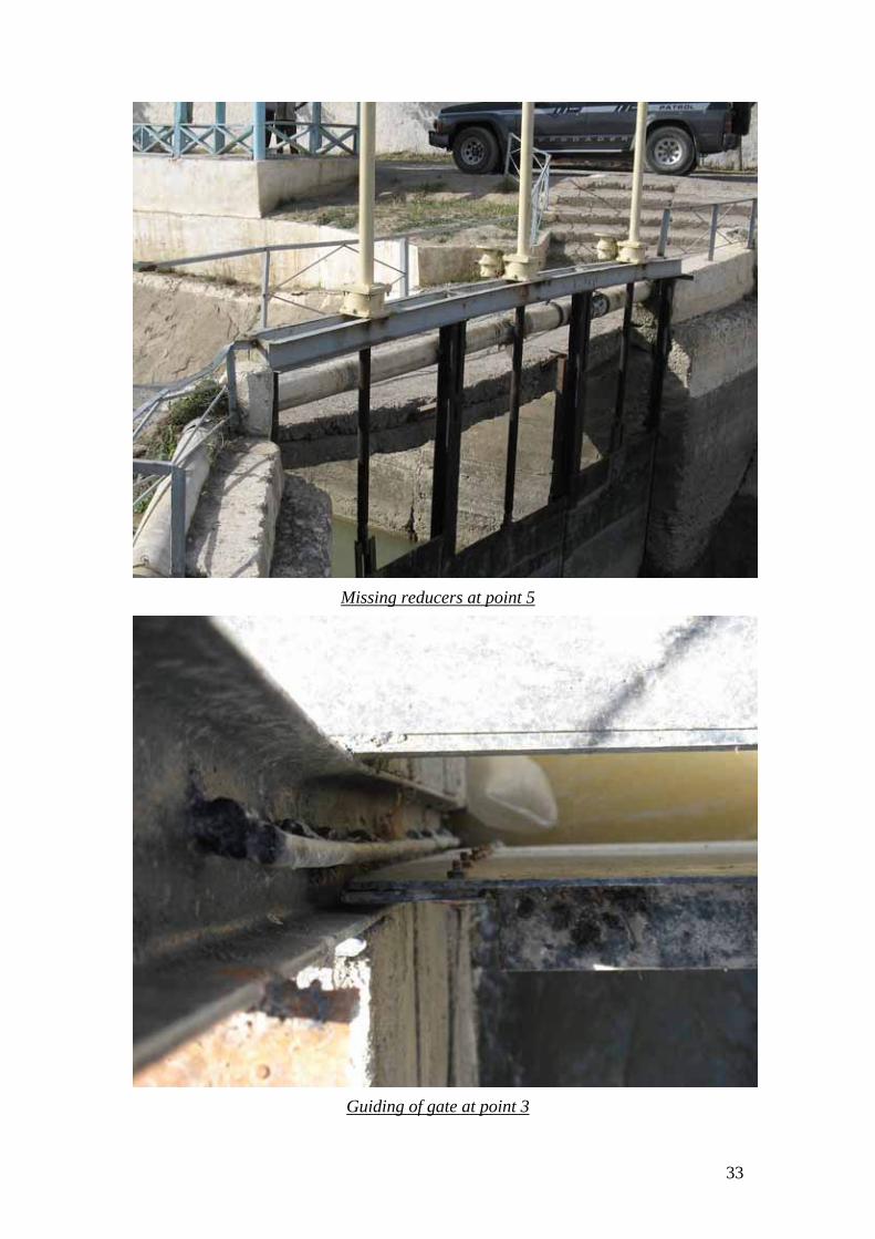
• Condition of the reducers:
- some reducers could not be operated, some others did not operate smoothly (e.g. point 2),
- most of the reducers are not in good condition, considering they were recently installed; (e.g. point 6),
- welding of the reducers to the gate frames is weak in most cases (welding by irregular points and not on the whole perimeter of reducer) and was found broken at several occasions (e.g. point 6),
- broken casing of reducer was also observed (e.g. point 3),
- some reducers were found missing (e.g. point 5).
• Condition of the gates:
- in many cases, the thickness of the gates did not seem appropriate to their size or their use, resulting in gates bent after operation (e.g. point 6, point 5),
- guiding of the gates is generally not accurate and restrictions to lateral movements were introduced through additional pieces of metal poorly welded (e.g. point 3),
- the gates screws were found several cases non vertical (e.g. point 4, point 6), possibly due to bad execution of installation and welding of reducers.
• Electrical equipment:
- electrical supply has been provided, but not completed in most sites: transformer installed, but not connected (e.g. point 5).
- electrical cable trays are either very old (e.g. point 6) or not available. Special care shall be taken that electrical cables are properly installed.
- electrical motors are not available for the gates of the diversion dam. For faster operation, it is recommended to have electrical motors in operating condition. This is not currently foreseen in the automation project.
- motors on the head gates of the canal appear very old, and should preferably be changed for reliable operation.
• Civil work :

28
- some footbridges are in very poor condition, resulting in unsafe working conditions for operators (e.g. point 4).
- the chain of the gate closest to right hand bank of the river diversion is broken. It is impossible to maneuver this gate.
The closing date of the contract with Gayur is by end of 2008, and the work by SIGMA by March 2009. It was provided that Gayur will supply motors with specifications from SIGMA to ensure quality equipment. SIGMA will provide the Gate Control Boxes (GCB), devices to command the motors. These boxes will be assembled in a plant outside SIGMA, and checked by SIGMA. According to information collected during the visit, some reducers would be made of steel part acting on the steel screw of the gates. For a long term operation, it is recommended that the reducer should be made of bronze, to increase life of the reducers. III. CONCLUSIONS ON THE READINESS FOR INSTALLATION OF SCADA EQUIPMENT Considering the above observations, the team of international experts considers that the KBG canal control structures are not ready for the installation of SCADA equipment. The Team recommends that before installation of automation equipment:
• All above described problems, and problems possibly identified during changes of gate positions should be corrected.
• KBG Canal Administration should systematically test the gate equipment. The following check-list is proposed:
o check that full opening of gates is possible, and their water tightness at closing;
o check that reducer operation is smooth;
o check installation of reducer (quality of welding, which must result in horizontal reducer and unbroken welding)
The team has no objection to the fact that SIGMA could proceed with the installation of equipment for remote monitoring including level sensors, transmission and processing of data. There are two prerequisite conditions to this installation:
• availability of electrical power at all sites,
• availability of buildings to host SIGMA equipment.
29
IV. OPERATIONAL STRATEGY UNDER SCADA The main objective of automation of the KBP should be to improve equity of unregulated water distribution and allocation, and to reduce the variations of flows delivered to water user groups which contribute to better on-farm water management. The most frequent mode of operation of a manually-operated canal is known as “upstream control”, under which the flow diverted at the head of the system is based on pre-determined or demand water requirements. For ease of operation, the water level should be maintained constant upstream of each control structure. This strategy limits the fluctuations of the flow delivered to secondary or branch canals and the frequency of adjustments of the gates at the heads of the canals. If the gates at the heads of the secondary canals are under automatic control to keep a target flow independently of the upstream water level in the main canal, there is much less constraint on the control of the water level in the main canal. Some fluctuations of the water level are admissible. This is particularly interesting for a run-of-river project as the KBG project. At low flows it can be useful to operate the system at the minimum level compatible with hydraulic conditions in the secondary canals in order to have some storage volume of flood waters in the main canal. This mode of operation will reduce seepage losses through broken concrete lining. A more in-depth study of the operation of the KBG might be needed. The present mode of operation under 6-day rotational system during low flows between rayons would have to be modified to be compatible with a SCADA system.
Damaged canal lining at point 4

30
Appendix: examples of problems observed on the gates and other hydro-mechanical equipment at Khoji Bakirgan Canal
Bent gate at point 6
Broken reducer support at point 6

31
Non-horizontal reducer at point 6
Broken reducer support at point 6

32
Bad condition of reducer at point 6
Broken reducer support at point 6
33
Missing reducers at point 5
Guiding of gate at point 3

34
Broken reducer casing at point 3
Broken reducer welding at point 2

35
ANNEX 1: MISSION SCHEDULE
May 8: Departure of Team Leader from Washington
May 9: Departure of the team from Paris
May 10: Arrival in Tashkent: preliminary meeting with Ismail Begimov and Interpreter Akmal Ortikov
May 11: Free
May 12: Meeting at SIC-ICWC and visit of BWO Syr Darya
May 13: Travel to Kojant, Tajikistan Visit of the Khoji-Bakirgan canal
May 14: Continuation of the visit Meeting with SDC in Chkalovsk town and joint visit of key structures Travel to Fergana
May 15: Travel to Kampiravvat, visit of the structure Visit of the South Fergana canal down to Hamza site (head of
Karkidon canal)
May 16: Visit of the SFC from Palvantash to end of canal
May 17: Meeting with SDC team in Kuva Visit of a transboundary small project
May 18: Transfer to Osh and short meeting with Head of AAB Canal Adm. Afternoon fee
May 19: Visit of the Aravan-Akbura canal and communication repeater Meeting with SDC-SIGMA chaired by Dr. Dukhovny
May 20: Attendance to the Official opening ceremony of AAB canal Automation project
Travel to Andijan
May 21: Travel to Uchkurgan Visit of the BWO structures (DP 15 and 66 and BFG)
May 22: Meeting at Uchkurgan with SDC mission and tests at DP 66 Travel to Akhunbabaev and visit of two structures.
May 23: Travel to Tashkent Short meeting at SDC
May 24: Report writing
May 25: Report writing
May 26: Debriefing Meeting at SIC-ICWC Finalization of mission report
May 27: Flight to Paris

36
ANNEX II: PERSONS MET DURING THE MISSION: SDC: Hanspeter Maag: Country Director for Kyrgyzstan and Uzbekistan Omina Islamova: Regional Water Sector Program Manager Christoph Morger: Senior Consultant Zafar Samadov: Senior NPO SCO Bakyt Mahmutov: NPO SCO SIC-ICWC Victor. Dukhovny: Director Ismail Begimov: Automation Expert Valeriy Tyugay: Water Allocation expert SIGMA Michael Tolstunov: Technical Director for Uzbekistan Sergey Vasilenko: Director, Kyrgyzstan BWO/Syr Darya Alexander Laktionov: Chief of Technical Division Husanbay Tukhtabayev: Head of BWO Naryn-Karadarya Nizomali Niyzov: Head of Naryn Syr-Darya Section Yulchyev Atham: Head of Communications and Automation South Fergana Canal Organization Rustamjon Rustamov: Head of SFC Administration Aravan-Akbura Canal Organization Mavlon Alimov: Head of AABC Administration Khoji-Bakirgan Canal Organization Zafar Maksudov: Head of KBC Administration