FEM STRUCTURAL ANALYSIS OF A HELICAL DRILL BY USING CATIA
6
Annals of the „Constantin Brancusi” University of Targu Jiu, Engineering Series , No. 2/2018 139 FEM STRUCTURAL ANALYSIS OF A HELICAL DRILL BY USING CATIA Nioaţă Alin, lecturer PhD. eng., “Constantin Brâncuşi” University of Târgu- Jiu, Romania ABSTRACT: With the aid of the finite element analysis method can be studied problems whose complexity is given by the complicated geometric configuration of the bodies, material inhomogeneities, anisotropy of the materials, composite materials, etc. These problems occur frequently in practice at the various stages of development of a product, even when a product already exists, but the problem of improving its characteristics is raised. KEY WORDS: CATIA, cutting tool, helical drill , force. 1. INTRODUCTION CATIA (Computer Aided Three Dimensional Interactive Applications) is a product of Dassault Systemes company, one of the most advanced integrated CAD/CAM/CAE platforms based on the latest technologies in the field of informatic industry [2],[3],[4]. Basic functionalities [2],[3],[4]: - advanced design of mechanical parts; - interactive producing of the assemblies; - automatic obtaining of projections of the current piece or ensemble; - the possibility of designing in a parameterized way; - allows designing the parts and assemblies directly in three dimensions, without first drawing the sketches in two-dimensional representation; - uses virtual prototypes that allow: -testing of resistance to various stresses; - verifying whether an assembly is dismountable or not; -verifying if the mobility of components, relative to each other, does not generate collisions; - has modular structure. Although the number of modules is very large, a few can be considered as basic [2],[3],[4]: - CATIA Sketcher - creates a sketch of a profile in two dimensions; - CATIA Part Design –is used for the construction of mechanical parts in three dimensions; - CATIA Assembly Design - generates a set of parts using various mechanical constraints for positioning them and for determining surface contacts; -CATIA Drafting - allows obtaining the work drawings of the parts and assemblies created; - CATIA Knowledge Advisor - allows parameterized design using specific tools such as formulas, parameters, rules and reactions, activated only after a pre- established condition has been met; - CATIA Composites Design - allows the creation of composite assemblies; - CATIA Analysis & Simulation - allows finite element analysis of parts / assemblies; - CATIA Machining - allows designing and simulation of operations on numerically controlled machines; 2. MODELLING OF THE PIECE In this stage it is considered a helical drill with a diameter of φ16
Transcript of FEM STRUCTURAL ANALYSIS OF A HELICAL DRILL BY USING CATIA
Annals of the „Constantin Brancusi” University of Targu Jiu, Engineering Series , No. 2/2018
139
FEM STRUCTURAL ANALYSIS OF A HELICAL DRILL
BY USING CATIA
Nioaţă Alin, lecturer PhD. eng., “Constantin Brâncuşi” University of Târgu-
Jiu, Romania
ABSTRACT: With the aid of the finite element analysis method can be studied problems whose complexity
is given by the complicated geometric configuration of the bodies, material inhomogeneities, anisotropy of
the materials, composite materials, etc. These problems occur frequently in practice at the various stages of
development of a product, even when a product already exists, but the problem of improving its
characteristics is raised.
KEY WORDS: CATIA, cutting tool, helical drill , force.
1. INTRODUCTION
CATIA (Computer Aided Three
Dimensional Interactive Applications) is
a product of Dassault Systemes company,
one of the most advanced integrated
CAD/CAM/CAE platforms based on the
latest technologies in the field of
informatic industry [2],[3],[4].
Basic functionalities [2],[3],[4]:
- advanced design of mechanical parts;
- interactive producing of the assemblies;
- automatic obtaining of projections of
the current piece or ensemble;
- the possibility of designing in a
parameterized way;
- allows designing the parts and
assemblies directly in three dimensions,
without first drawing the sketches in
two-dimensional representation;
- uses virtual prototypes that allow:
-testing of resistance to various
stresses;
- verifying whether an assembly is
dismountable or not;
-verifying if the mobility of
components, relative to each
other, does not generate
collisions;
- has modular structure.
Although the number of modules is
very large, a few can be considered as
basic [2],[3],[4]:
- CATIA Sketcher - creates a sketch of a
profile in two dimensions;
- CATIA Part Design –is used for the
construction of mechanical parts in three
dimensions;
- CATIA Assembly Design - generates a
set of parts using various mechanical
constraints for positioning them and for
determining surface contacts;
-CATIA Drafting - allows obtaining the
work drawings of the parts and
assemblies created;
- CATIA Knowledge Advisor - allows
parameterized design using specific tools
such as formulas, parameters, rules and
reactions, activated only after a pre-
established condition has been met;
- CATIA Composites Design - allows
the creation of composite assemblies;
- CATIA Analysis & Simulation -
allows finite element analysis of parts /
assemblies;
- CATIA Machining - allows designing
and simulation of operations on
numerically controlled machines;
2. MODELLING OF THE
PIECE
In this stage it is considered a
helical drill with a diameter of φ16

Annals of the „Constantin Brancusi” University of Targu Jiu, Engineering Series , No. 2/2018
140
(figure 1) with the following
characteristics:
- angle of point: 2χ=116o-120o;
- angle of dip of the helical grooves:
ω=28o-29o;
- seat angle: α= 10o-12o.
The drill is made of Rp3 fast steel with
the following international equivalence
(Table 1):
Table 1. Rp3 symbolization and its international equivalence
SR JIS GOST Werkstoff Bohler AISI/SAE UNE
Rp3 SKH2 R18 W.1.3355 S200 T1 F5520
18-0-1
Figure 1. Helical drill
3. FEM Analysis
After solid modelling in the CATIA
Part Design module, the piece is
considered to be made of a material
(steel) having the following physical and
mechanical properties, important during
analysis: Young's module
(2x10¹¹N/mm2), Poisson's coefficient
(0.266) , density (7860 kg/m3),
coefficient of thermal expansion
(1,17x10⁻⁵ oK), permissible strength
(2,5x10⁸ N/m2) [4],[5].
The CATIA Generative Structural
Analysis module is accessed from the
Start - Analysis & Simulation menu and
the Static Case type is determined , the
specification shaft simultaneously
displaying the element bearing the same
name . Although the CATIA program
defines the network of nodes and
elements(discretization), it is
recommended to edit this and determine
the size of the finite element, the
maximum tolerance between the
discretized model and the real model
used in the analysis (Absolute sag), the
type of element(Element type), and so on
[1],[2],[3]..
Annals of the „Constantin Brancusi” University of Targu Jiu, Engineering Series , No. 2/2018
141
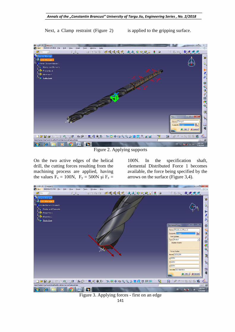
Next, a Clamp restraint (Figure 2) is applied to the gripping surface.
Figure 2. Applying supports
On the two active edges of the helical
drill, the cutting forces resulting from the
machining process are applied, having
the values Fx = 100N, Fy = 500N şi Fz =
100N. In the specification shaft,
elemental Distributed Force 1 becomes
available, the force being specified by the
arrows on the surface (Figure 3,4).
Figure 3. Applying forces - first on an edge

Annals of the „Constantin Brancusi” University of Targu Jiu, Engineering Series , No. 2/2018
142
Figure 4. Applying forces on the second edge
Once the restrictions and loading
have been established, the actual step of
the calculation (analysis) follows. By
clicking the Compute icon on the toolbar
All option is selected , the first effect of
the action being to update the Static Case
Solution (Figure 5). Once the calculation
is complete, the user has the Image bar
tools available to view the results. The
specifications tree is completed according
to the inserted images. Figure 6 shows
the image (using Von Mises Stress,
Deformation, Principal Stress and
Precision) corresponding to the
calculation of the piece model and load
considered, specifying that the
deformations are graphically presented
slightly overstated in order to ease the
stage of determining the conclusions of
the analysis [1],[5].
Annals of the „Constantin Brancusi” University of Targu Jiu, Engineering Series , No. 2/2018
143
Figure 5. Discredited drill
Figure 6. Discredited drill but viewing tense areas (red - strong, blue - weak)
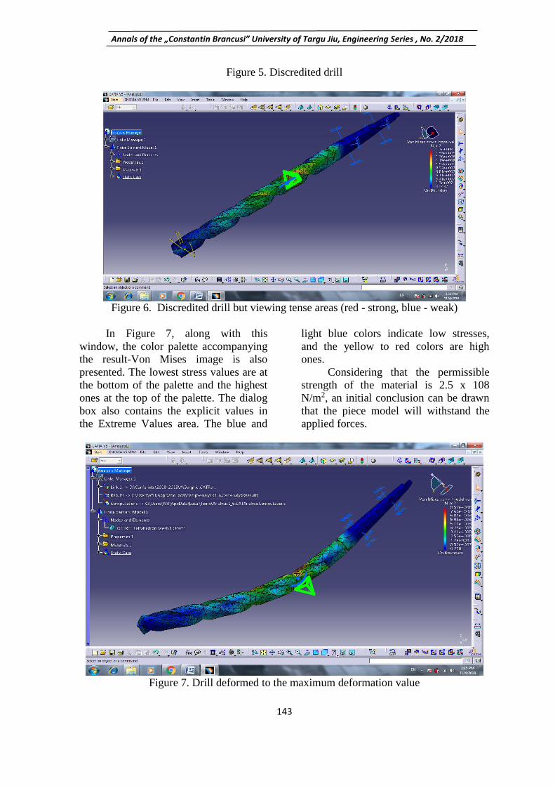
In Figure 7, along with this
window, the color palette accompanying
the result-Von Mises image is also
presented. The lowest stress values are at
the bottom of the palette and the highest
ones at the top of the palette. The dialog
box also contains the explicit values in
the Extreme Values area. The blue and
light blue colors indicate low stresses,
and the yellow to red colors are high
ones.
Considering that the permissible
strength of the material is 2.5 x 10⁸
N/m2, an initial conclusion can be drawn
that the piece model will withstand the
applied forces.
Figure 7. Drill deformed to the maximum deformation value

Annals of the „Constantin Brancusi” University of Targu Jiu, Engineering Series , No. 2/2018
144
4.CONCLUSIONS
Finite element analysis using the
CATIA program is a modern method for
studying different contacts, allowing the
determination of important parameters
for the study of different contacts. In the
case of hertz contacts, accurate
information on the state of stresses at the
contact level is obtained. The point
contact analysis using the classical
method (Hertz theory) did not allow such
accurate results to be obtained. Von
Mises stress determination allows a stress
state analysis thus allowing for a correct
quantification of this state and the
possibility of identifying the deterioration
that occurs.
BIBLIOGRAPHY
[1] Ciofu Florin - Hip implant analysis
with CATIA, Revista Fiabilitate şi
Durabilitate, Nr.2/2017, ISSN 1844-
640X, pag.99.
[2] Ghionea, I.G. – CATIA v5 –
culegere de aplicaţii pentru activităţi de
laborator, format electronic, Universitatea
Politehnică Bucureşti, 2015;
[3] Ghionea, I.G. – CATIA v5 – aplicaţii
ȋn inginerie mecanică, Editura BREN,
Bucureşti, 2009;
[4] Ghionea, I.G. – Proiectare asistată ȋn
CATIA v5 – elemente teoretice şi
aplicaţii, Editura BREN, Bucureşti,
2014;
[5] Olariu, V., Brătianu, C. - Modelare
numerică cu elemente finite, Editura
Tehnică, Bucureşti, 1986.