
FEM Modeling: Introduction
27
Introduction to FEM 6 FEM Modeling: Introduction IFEM Ch 6 – Slide 1
Transcript of FEM Modeling: Introduction

Introduction to FEM
6FEM Modeling:
Introduction
IFEM Ch 6 – Slide 1

Introduction to FEM
FEM Terminology
degrees of freedom (abbrv: DOF)
state (primary) variables: displacements in mechanics
conjugate variables: forces in mechanics
stiffness matrix
master stiffness equations
K u = f
K u = f + fIM
IFEM Ch 6 – Slide 2

Introduction to FEM
Application State (DOF) vector u Forcing vector fProblem represents represents
Structures and solid mechanics Displacement Mechanical force
Heat conduction Temperature Heat flux
Acoustic fluid Displacement potential Particle velocity
Potential flows Pressure Particle velocity
General flows Velocity Fluxes
Electrostatics Electric potential Charge density
Magnetostatics Magnetic potential Magnetic intensity
Physical Significance of Vectors u and f in Miscellaneous FEM Applications
IFEM Ch 6 – Slide 3

Introduction to FEM
Where FEM Fits (from Chapter 1)
Physicalsystem
Modeling + discretization + solution error
Discretization + solution error
Solution error
Discrete model
Mathematicalmodel
CONTINUIFICATIONREALIZATION &IDENTIFICATION
IDEALIZATION DISCRETIZATION SOLUTION
FEM Discretesolution
IFEM Ch 6 – Slide 4
Introduction to FEM
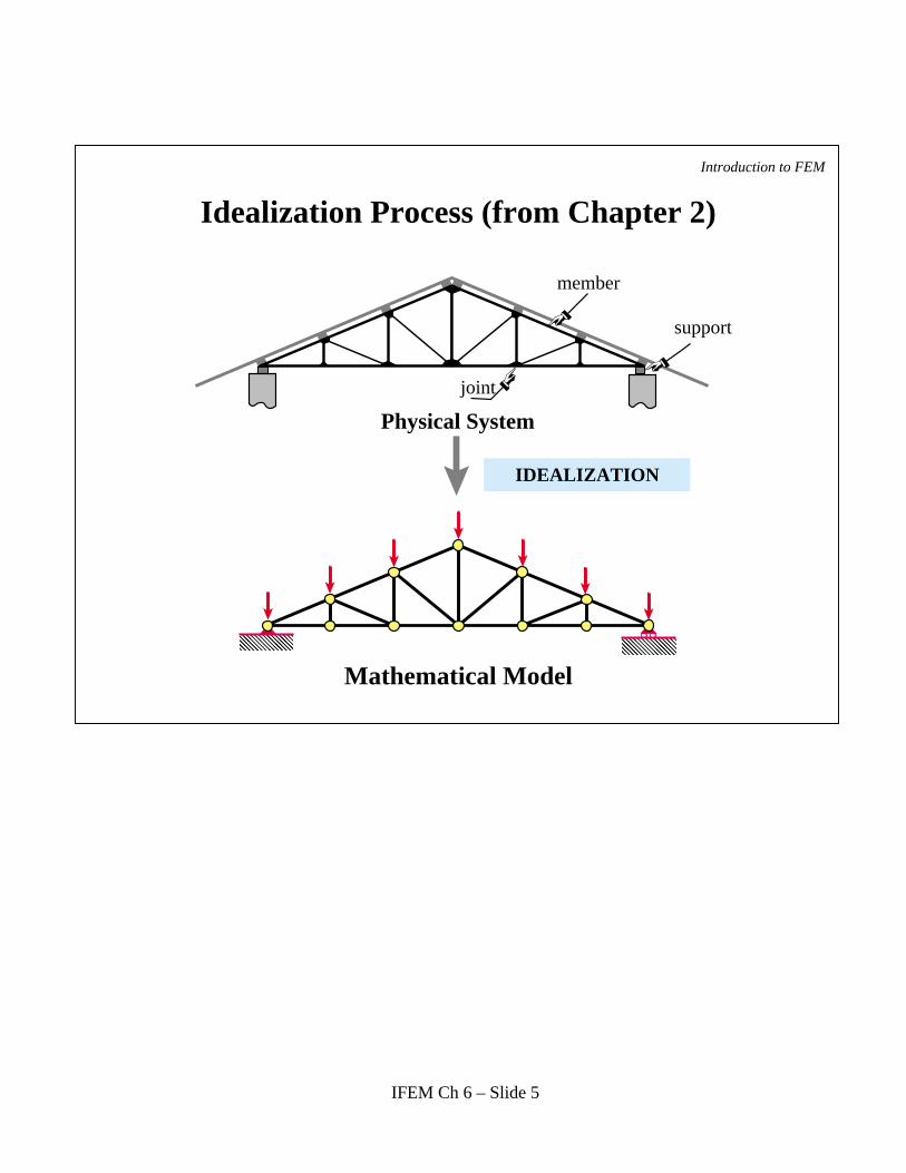
Idealization Process (from Chapter 2)
joint
Physical System
support
member
IDEALIZATION
��
��
��
��
��
��
Mathematical Model
IFEM Ch 6 – Slide 5

Introduction to FEM
Mathematical Model Definition
A model is a symbolic device built to simulate and predict aspects of behavior of a system
Scaled fabricated version of a physical system(think of a car or train model)
Simulation oriented definition
Traditional definition
IFEM Ch 6 – Slide 6
Introduction to FEM
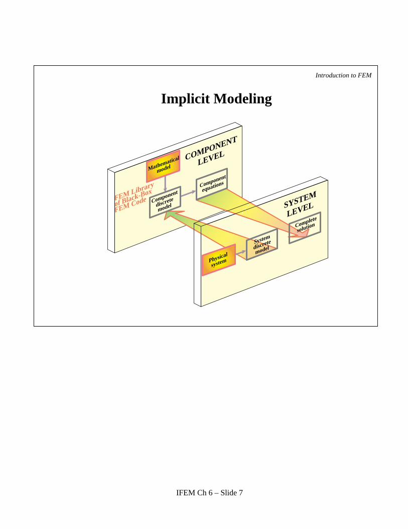
Implicit Modeling
FEM Library
of Black-Box
FEM Code Component
discrete
model
Component
equations
Physical
system
System
discrete
model
Complete
solution
Mathematical
model
SYSTEM
LEVEL
COMPONENT
LEVEL
IFEM Ch 6 – Slide 7

Introduction to FEM
Recall the "Breakdown" DSM Steps
DisconnectionLocalizationMember (Element) Formation -> generic elements
Breakdown
Let Stop Here and Study Generic Elements next
IFEM Ch 6 – Slide 8

Introduction to FEM
... Because Most of the Remaining DSM Steps
GlobalizationMergeApplication of BCsSolutionRecovery of Node Forces
are Element Independent
IFEM Ch 6 – Slide 9

Introduction to FEM
Attributes of Mechanical Finite Elements
DimensionalityNodes serve two purposes: geometric definition home for DOFs (connectors)
Degrees of freedom (DOFs) or "freedoms"Conjugate node forces
Material propertiesFabrication properties
IFEM Ch 6 – Slide 10
Introduction to FEM
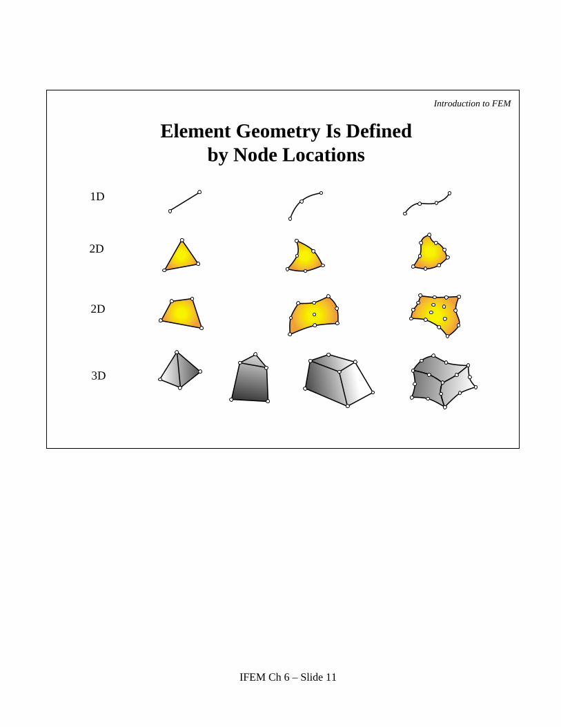
Element Geometry Is Defined by Node Locations
1D
2D
2D
3D
IFEM Ch 6 – Slide 11

Introduction to FEM
Classification of Mechanical Finite Elements
Primitive Structural
Continuum
Special
Macroelements
Substructures
Superelements
IFEM Ch 6 – Slide 12

Introduction to FEMPrimitive Structural Elements
(often built from MoM models) Physical
StructuralComponent
Finite ElementDiscretization
bar
beam
tube, pipe
spar (web)
shear panel(2D version of above)
MathematicalModel Name
IFEM Ch 6 – Slide 13

Introduction to FEM
Continuum Elements
plates 3D solids
Physical Finite elementidealizationPhysical Finite element
idealization
IFEM Ch 6 – Slide 14

Introduction to FEM
Special Elements
Infinity
Infinite element
Crackelement
Honeycombpanel
double node
IFEM Ch 6 – Slide 15

Introduction to FEM
MacroElements
IFEM Ch 6 – Slide 16

Introduction to FEM
Substructures
IFEM Ch 6 – Slide 17

Introduction to FEM
Substructures (cont'd)
S1
S2
S3
S4
S5
S6
IFEM Ch 6 – Slide 18

Introduction to FEM
An Early Use of FEM SubstructuringBoeing 747
CARGO DOOR CABIN ANALYSIS
WING BODY INTERSECTION ANALYSIS4 substructures,12549 elements
4266 nodes, 25596 freedoms
747 Regions Analyzed with FEM-DSM at Boeing
Global Analysis: 1966Local Analysis (shaded
regions): 1967-68First flight: 1970
IFEM Ch 6 – Slide 19
Introduction to FEM
Boundary Conditions (BCs)
The most difficult topic for FEM program users ("the devil hides inthe boundary")
Two typesEssential
Natural
IFEM Ch 6 – Slide 20

Introduction to FEM
Boundary Conditions Essential vs. Natural
1. If a BC involves one or more DOF in a direct way, it is essential and goes to the Left Hand Side (LHS) of Ku = f
2. Otherwise it is natural and goes to the Right Hand Side (RHS) of Ku = f
Recipe:
IFEM Ch 6 – Slide 21

Introduction to FEM
Examples of Structural Models:Machine Component (Mech. Engrg)
IFEM Ch 6 – Slide 22

Introduction to FEM
Examples of Structural Models:Dam under Ground Motion (Civil Engrg)
����������������
������������������
���������������������������
������������������
Cavitating volume
Base rock
Saturated soilUnsaturated fill
Concrete
Base ground motion
Water
Sandstone
IFEM Ch 6 – Slide 23

Introduction to FEM
Examples of Structural Models:Rocket Nozzle (Aerospace Engrg)
������
GRAPHITE
GLASS FILAMENTGLASS FABRIC
STEEL SHELLASBESTOSINSULATOR
(a) Typical solid rocket nozzle (Aerojet Corp., 1963)
Rotational axis
(b) Finite element idealization
21.37"
IFEM Ch 6 – Slide 24

Examples of Structural Models:SuperTanker (Marine Engrg)
A
B
Neutral Axis
Cross section of tanker
Typical internal structure of tanker
Centerline Girder Longitudinal
Web Frame
Stringer
Introduction to FEM
IFEM Ch 6 – Slide 25

Introduction to FEM
Examples of Structural Models: F16 External View (Aero)
IFEM Ch 6 – Slide 26

Examples of Structural Models: F16 Internal Structure (Aero)
Introduction to FEM
IFEM Ch 6 – Slide 27