Fei Bao F-100 Super Sabre - · PDF file · 2014-01-14Fei Bao F-100 Super Sabre ......
15
Fei Bao F-100 Super Sabre Thank you for buying our large scale F-100 Super Sabre, which has been developed to be quick to assemble and a pleasure to own and fly. The F-100 is a large, heavy and sophisticated model and as such it is vital that great care and attention is taken during assembly to ensure a safe and reliable airframe. You have invested a significant sum in your model so it is false economy to use any items to complete the aircraft that are not of the quality required; this covers everything from adhesives, through turbine, radio equipment and on-board power supplies etc. If at any point during the assembly you are in any doubt about the next step to take please contact the dealer where you purchased your F-100 – turbine powered models are not the place for guesswork! It is highly recommended that you carefully inspect all parts of your F-100 before starting assembly, if there appear to be any faulty parts or items missing please contact your dealer for advice/replacement. If you have not built a large scale turbine model until now we suggest that you find a local modeller who has and ask them to act as a mentor/second pair of eyes, to ensure the model is assembled to the highest standards. Be aware that depending on the turbine being used, the on-board radio equipment, batteries being used etc that the model may weigh more than 20Kg without fuel, or 25 Kg with fuel, and that certain countries have restrictions or procedures in place for models over these limits. If you are unsure of the regulations in place in your country please contact your national modelling authority for guidance. When the model is ready to fly we strongly suggest finding a site with a long hard surface runway, even if this means travelling some distance. Many models have been destroyed on their first flight due to a take-off or landing incident on a short runway, often due to overshooting on the first landing, when a turbine takes several seconds to accelerate from idle to full power. Having a long runway available eliminates this risk and reduces the stress level on the pilot, allowing him to concentrate more on flying the model. If you have never flown a highly loaded swept wing scale jet please consider the option of getting a pilot that is experienced in this type of model to carry out the first flight – this allows the model to be trimmed correctly before you take control. Parts listing: Forward Fuselage Section w/Canopy & Hatch Rear Fuselage Section w/Tailcone Right Wing Panel w/Aileron, Flap and Slat Left Wing Panel w/Aileron, Flap and Slat Right All Flying Tailplane Left All Flying Tailplane Fin/Rudder Intake Trunking Fuel Tank Set Twin Wall Tailpipe Control Accessories Optional Parts:
Transcript of Fei Bao F-100 Super Sabre - · PDF file · 2014-01-14Fei Bao F-100 Super Sabre ......
Fei Bao F-100 Super Sabre Thank you for buying our large scale F-100 Super Sabre, which has been developed to be quick to assemble and a pleasure to own and fly. The F-100 is a large, heavy and sophisticated model and as such it is vital that great care and attention is taken during assembly to ensure a safe and reliable airframe. You have invested a significant sum in your model so it is false economy to use any items to complete the aircraft that are not of the quality required; this covers everything from adhesives, through turbine, radio equipment and on-board power supplies etc. If at any point during the assembly you are in any doubt about the next step to take please contact the dealer where you purchased your F-100 – turbine powered models are not the place for guesswork! It is highly recommended that you carefully inspect all parts of your F-100 before starting assembly, if there appear to be any faulty parts or items missing please contact your dealer for advice/replacement. If you have not built a large scale turbine model until now we suggest that you find a local modeller who has and ask them to act as a mentor/second pair of eyes, to ensure the model is assembled to the highest standards. Be aware that depending on the turbine being used, the on-board radio equipment, batteries being used etc that the model may weigh more than 20Kg without fuel, or 25 Kg with fuel, and that certain countries have restrictions or procedures in place for models over these limits. If you are unsure of the regulations in place in your country please contact your national modelling authority for guidance. When the model is ready to fly we strongly suggest finding a site with a long hard surface runway, even if this means travelling some distance. Many models have been destroyed on their first flight due to a take-off or landing incident on a short runway, often due to overshooting on the first landing, when a turbine takes several seconds to accelerate from idle to full power. Having a long runway available eliminates this risk and reduces the stress level on the pilot, allowing him to concentrate more on flying the model. If you have never flown a highly loaded swept wing scale jet please consider the option of getting a pilot that is experienced in this type of model to carry out the first flight – this allows the model to be trimmed correctly before you take control. Parts listing: Forward Fuselage Section w/Canopy & Hatch Rear Fuselage Section w/Tailcone Right Wing Panel w/Aileron, Flap and Slat Left Wing Panel w/Aileron, Flap and Slat Right All Flying Tailplane Left All Flying Tailplane Fin/Rudder Intake Trunking Fuel Tank Set Twin Wall Tailpipe Control Accessories Optional Parts:
Tricycle Retract Set with Oleos, Wheels, Brakes etc Scale Cockpit Kit Drop Tank Set Bomb Set Refuelling Probe Required to complete: 180 to 240 Newton Turbine: A Jetcat P200 turbine was used in the prototype model and this gave a perfect balance between power and weight, without requiring too much fuel to be carried, If a larger and more powerful turbine is to be used it is recommended that full power is not used when the model is diving, as this may overstress the airframe. Radio: A 12 to 18 channel radio will be required to allow all the functions of the F-100 to be fully utilised. Due to the size and weight of the model it is highly recommended that twin receivers and battery packs are fitted to allow a degree of redundancy in the event of the receiver or battery failure. Servos: The F-100 requires a total of 11 high quality servos for the flying surfaces and a further metal geared high power servo for nose wheel steering. The prototype model used Futaba servos all round - S9074SB programmable servos of 20 kg.cm torque for the ailerons (2 req), slats (4 req), flaps (2 req) and rudder (1 req). The all flying tailplane halves used BLS 152 servos of 31 kg.cm torque whilst the nosewheel steering utilised an S3305 of 8.9kg.cm torque. Assembly Instructions: Wings: Commence wing assembly by removing the large cover/door hinge mount from the wing panels by undoing the three screws, then unscrew the main undercarriage units from their mounts, disconnecting the landing gear door linkage from the leg, and undoing the allen screw that attaches the aluminium support strut to the leg. It is recommended that at this stage the security of all the allen screws used on the landing gear units and oleo legs are checked for security, use of a threadlocking compound on all screws is suggested whilst the landing gear is removed from the model – do not forget the allen screws hidden behind the upper pivot pin of the scissor links. Remove the aileron servo cover from the wing then use a countersink bit in an electric drill to form neat countersinks in the outer side of the cover, these should be just deep enough to allow the securing screws to sit flush with the outer surface of the hatch. Note that the hatch on the left has also had the slot opened up for the pushrod/clevis.

Fit the “L” brackets to the aileron servo – note that due to the lack of vibration that is a characteristic of turbine powered models it is normal to mount the servos without the rubber grommets and ferrules that are required for use in models powered by 2 or 4 stroke I/C engines. This has the added benefit of making the entire control system more rigid and less prone to damaging flutter.
Offer the aileron servo into place on the underside of the hatch and temporarily hold in position with the mounting screws. Fit the servo horn to the servo and mark the hatch where the pre-formed slot has to be enlarged to allow full deflection of the servo arm – including trim range. Remove servo from the hatch and use a Dremel tool or similar to open up the slot you have marked, Permagrit tools are ideal to finish off the slot neatly. Fit the aileron servo to the hatch, making sure all screws are completely tight. Repeat the process to fit the rudder servo to its hatch, then also fit the slat and flap servos to their hatch covers, note that the slat hatch covers have no slots as the pushrods are positioned internally.

Fit suitable length extension lead to the aileron servo, it is highly recommended that a heavy duty lead is used here due to the possible voltage drop due to the length of lead required. All extension plugs and leads must be secured to each other during assembly, options include heatshrink tubing over the plug/socket, vinyl tape, binding wire or one of the proprietary lead locks. Feed the extension lead down the wing to the root, the use of a piece of thin wire, plastic tube or even a length of solder can be useful here. Screw the aileron servo hatch into place on the wing. Cover the underside of the aileron directly behind the aileron servo horn position with masking tape, then use a ruler or straight edge to draw a line across the aileron in line with the servo horn. Draw a second line 5mm outboard of the previously drawn line – this is the centre line of the slot for the aileron control horn. Offer the aileron horn into place, and position it so that the control linkage hole in the horn is directly over the hinge line of the aileron – mark the front and rear of the base of the horn onto the masking tape. Very carefully use a suitable diameter router bit in a Dremel or similar high speed multi tool to cut a slot along the line drawn from the servo horn, and between the front and rear marks made earlier – use eye protection! Open up the hole to the correct width and depth using Permagrit files – be VERY careful to clean out the slot only as far as required and make sure not to cut into the inside of the top skin of the aileron, do NOT break through the skin. Check the fit of the control horn into the slot, when happy use Permagrit or coarse sandpaper to roughen the base of the control horn. Remove the masking tape left on the aileron from the previous steps and then use four separate pieces of tape along the edges of the slot, leaving around a 1mm gap. Glue the horn into place in the slot using Hysol, ensuring adequate glue is used, then make sure that the horn is in the exact position required, wipe off the excess glue, and remove the masking tape protecting the paint finish before the Hysol begins to cure, which would make the masking tape almost impossible to remove cleanly. Recheck the position of the horn, then put to one side until the Hysol is fully cured. An example of a typical horn installation is shown below.

Assemble the aileron pushrod using a ball joint at one end and a clevis at the other and check for full and free travel, making sure that the servo arm or pushrod cannot jam in any position. It may be necessary to bend the pushrod slightly to allow adequate clearance to the end of the slot in the servo hatch, but any such bend should be kept to a minimum to avoid any flexing and thus any possibility of control surface flutter.
Repeat the above procedure for the flap servo, horn, pushrod etc

The slat servos should now be fitted to their hatch mounts, after which the pushrods should be made up and then connected to the horns pre-installed within the slats. Adjust the lengths of the pushrods until the slats close and open fully, without the servos being stalled at either end of their travel – this is a little fiddly to complete so a reasonable degree of patience is required, do not try to do this job in a hurry! Assuming that the optional electric retracts have been fitted the gear doors should be operated by servos or electric actuators. Ensure that these are securely installed and that the doors operate correctly without the servos/actuators consuming excessive current. Sequencing of the doors can be by a separate sequencer or via the radio or a PowerBox unit if it includes a sequencer. Note that the F-100 has some doors which remain open when the landing gear is extended, whilst others open only during extension/retraction and are otherwise always closed; Normally closed doors: Large nosewheel door, fuselage main gear doors. Doors open when gear is extended: Small front nosewheel door, all wing doors. Forward Fuselage Initial Assembly Remove the nose retract unit in the similar manner to the mains, and carry out the same checks as were done to them, ensuring reliable operation and that all screws have had a threadlock compound applied and that they are all fully tight. Fit the nosewheel steering servo into the mounting plate and secure with screws – note that the rear screws also secure the noseleg brace – use a threadlocking compound on the servo mounting screws, and remember that the servo can be fitted without grommets or ferrules. A metal geared servo is required and it is recommended that a servo with a minimum of 8 - 10kg.cm torque is used. Fit a suitable strong servo arm to the nosewheel steering servo and connect the steering linkage to the servo arm, ensuring that the nosewheels are perfectly straight when the servo is centred.

Refit the nose retract unit into the model – note that prior to fitting thin cyano glue can be poured into the screw holes in the retract unit mounting plates to toughen the wood. Make sure the glue is completely cured before finally re-fitting the nose retract unit. Run the nosewheel steering servo lead out of the nose undercarriage bay and attach extension lead as required to be able to connect to the receiver being used. Connect air lines to the underfuselage airbrake, and check for any leaks, as this is harder to do with the fuel tanks in place. At the same time run any remaining air lines and all extension and electrical leads from the front of the forward fuselage back to the wing mount area and the rear for connection to the tailplane and rudder extension leads.
Assemble the fuel tanks, check for leaks and then check that they fit correctly into the forward section of the fuselage – it is quite tight to get the tanks into place but do persevere, it can be done. Once satisfied the tanks can be glued into place using a silicon sealant or similar, ideally only gluing around the exposed edges, so that a flexible long bladed knife can be used to cut the tanks free if they need to ever be removed at a later date.

Rear Fuselage and Tail Surfaces

Before installing the tailplane halves they must be balanced so that they will remain level when the tail pivot shaft is inserted into the bearings in the tailplane mounts. Cut a small hole into the root face of the leading edge of each tailplane half and then fill the very front of the tailplane with a lead/epoxy mix until the tailplane is accurately balanced. Once the epoxy is dry the tailplane halves can be slid into place through the bearings and the tailplane horns. Fit the tailplane servos into their mounts, note that very powerful metal geared servos are required here, preferably digital for their excellent holding power, Futaba BLS 152 servos with 31.0Kg.cm torque were used in the prototypes.
Assemble the elevator linkages carefully, making sure that they are exactly the same length, very heavy duty M3 linkages with large heavy duty balljoints were used in the prototypes, as these linkages are under very high stress in certain flight regimes. Fit the linkages to the servos and the tailplane horns, making sure that with the servos at neutral the tailplane horns are exactly vertical. Once satisfied the 2 allen bolts on each tailplane horns should be fully tightened, ensuring that the tailplane halves do not move whilst this is being done. For added security a small dab of epoxy or drop of cyano can be used to lock the tailplane pivot shaft to the horn.
Fit the rudder servo into the fin and complete the rudder linkage/horn installation in the same manner as the aileron servo installation.
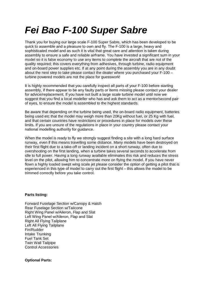
The rudder servo lead runs out through the bottom of the fin and into the fuselage, where it connects to an extension lead. Fit the fin/rudder assembly to the fuselage and securely tighten the fin post clamping screws.
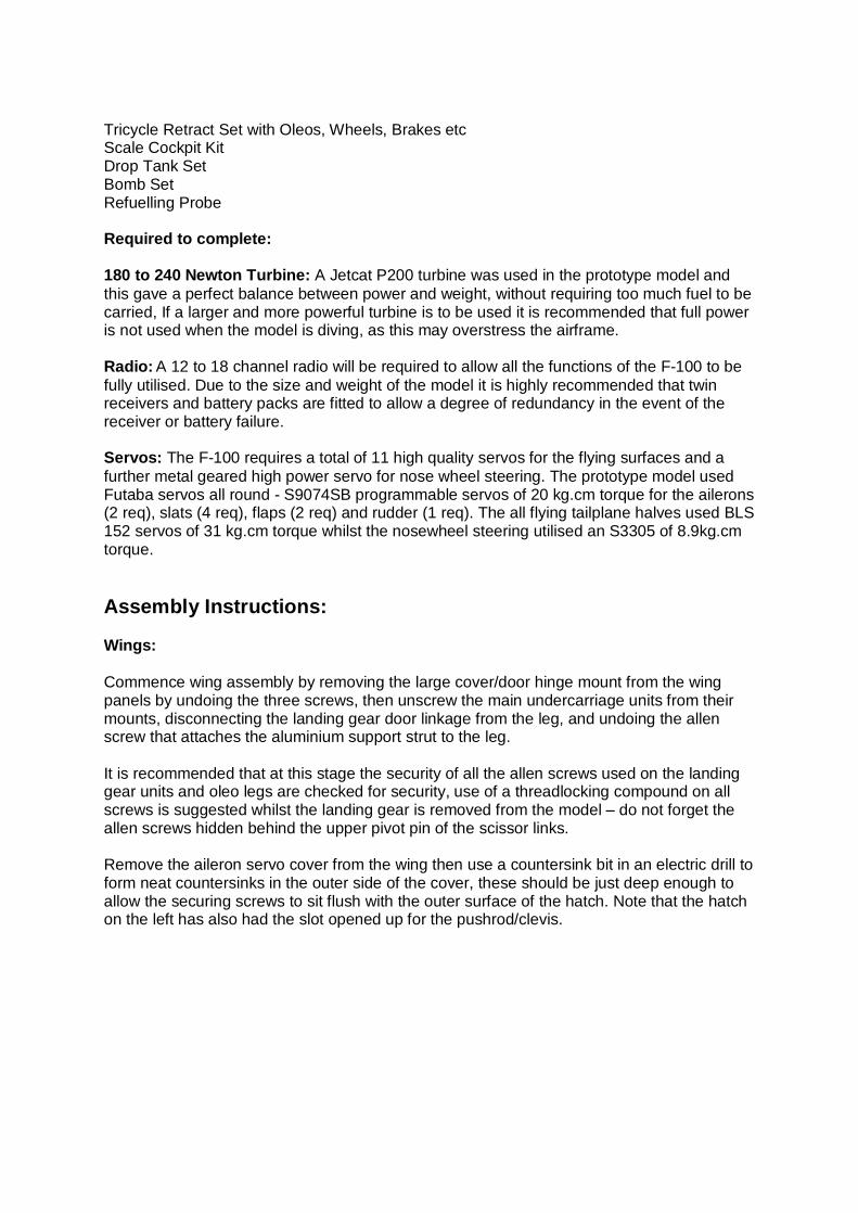
The extension leads for the rudder and tailplane servos should be retained to the fuselage sides so that they are well away from the tailpipe, using commercial servo lead mounts or by wrapping the leads in paper masking tape and then using cyano to glue the masking tape to the fuselage. It is suggested that the extension leads used are the correct length to enable all the connections to be made at the fuselage joint, as this makes assembly/disassembly of the fuselage much simpler.
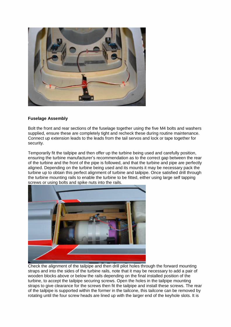
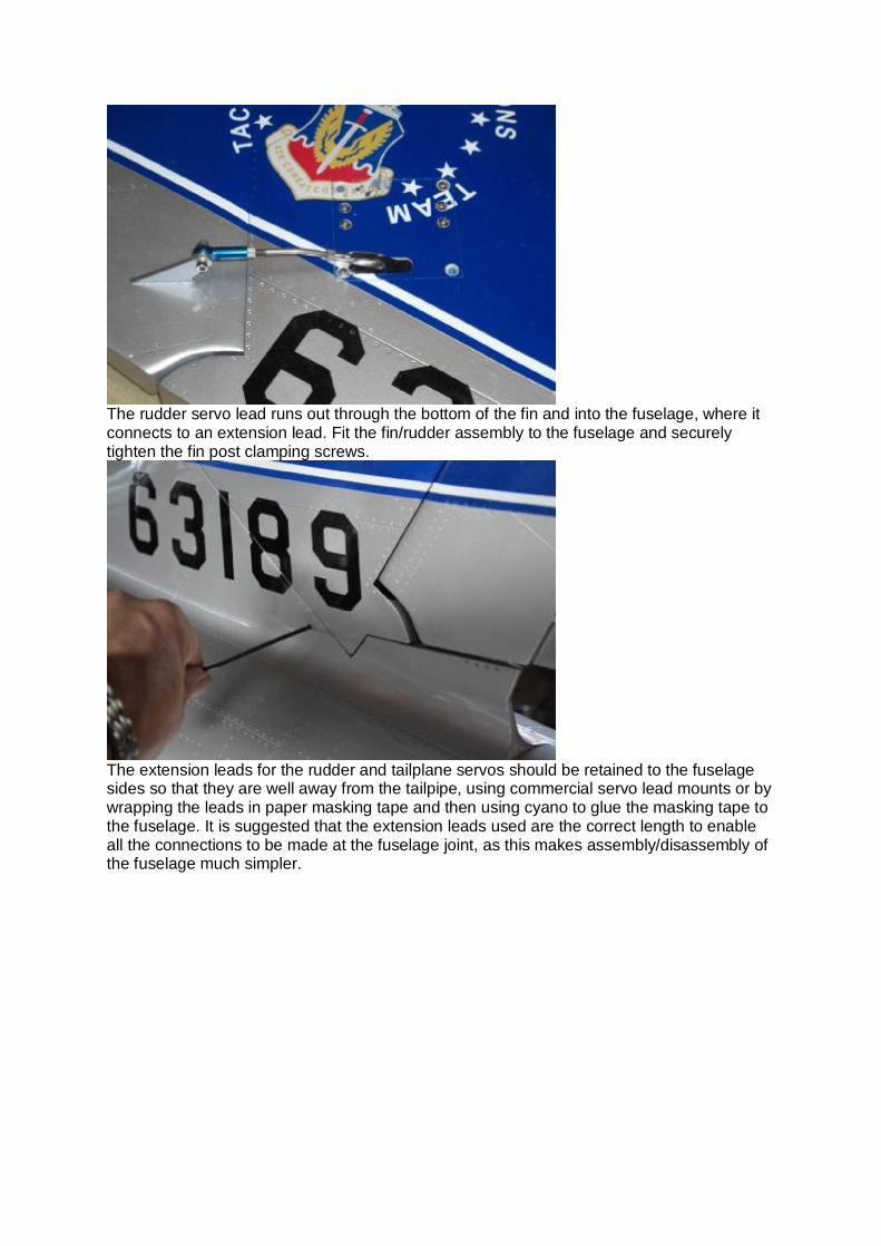
Fuselage Assembly Bolt the front and rear sections of the fuselage together using the five M4 bolts and washers supplied, ensure these are completely tight and recheck these during routine maintenance. Connect up extension leads to the leads from the tail servos and lock or tape together for security. Temporarily fit the tailpipe and then offer up the turbine being used and carefully position, ensuring the turbine manufacturer’s recommendation as to the correct gap between the rear of the turbine and the front of the pipe is followed, and that the turbine and pipe are perfectly aligned. Depending on the turbine being used and its mounts it may be necessary pack the turbine up to obtain this perfect alignment of turbine and tailpipe. Once satisfied drill through the turbine mounting rails to enable the turbine to be fitted, either using large self tapping screws or using bolts and spike nuts into the rails.
Check the alignment of the tailpipe and then drill pilot holes through the forward mounting straps and into the sides of the turbine rails, note that it may be necessary to add a pair of wooden blocks above or below the rails depending on the final installed position of the turbine, to accept the tailpipe securing screws. Open the holes in the tailpipe mounting straps to give clearance for the screws then fit the tailpipe and install these screws. The rear of the tailpipe is supported within the former in the tailcone, this tailcone can be removed by rotating until the four screw heads are lined up with the larger end of the keyhole slots. It is
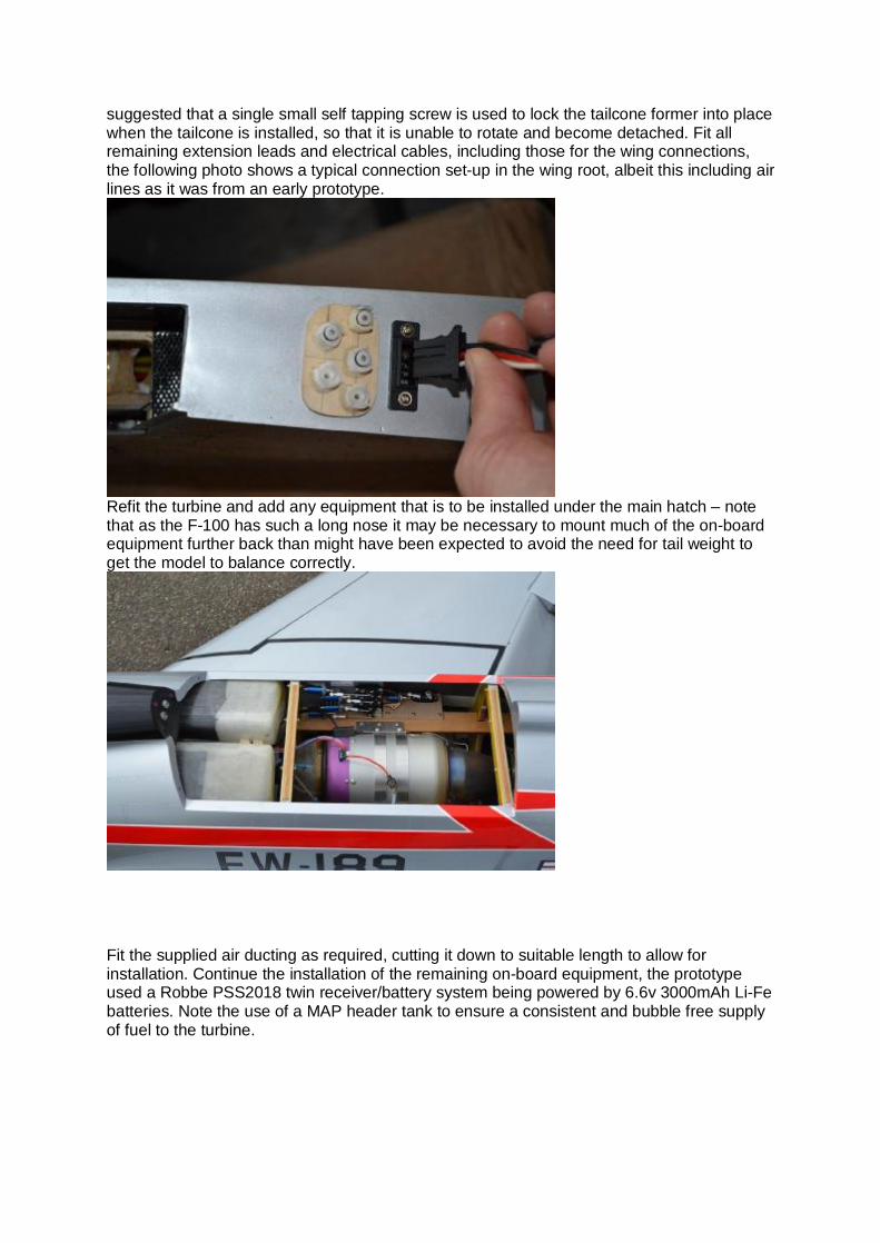
suggested that a single small self tapping screw is used to lock the tailcone former into place when the tailcone is installed, so that it is unable to rotate and become detached. Fit all remaining extension leads and electrical cables, including those for the wing connections, the following photo shows a typical connection set-up in the wing root, albeit this including air lines as it was from an early prototype.
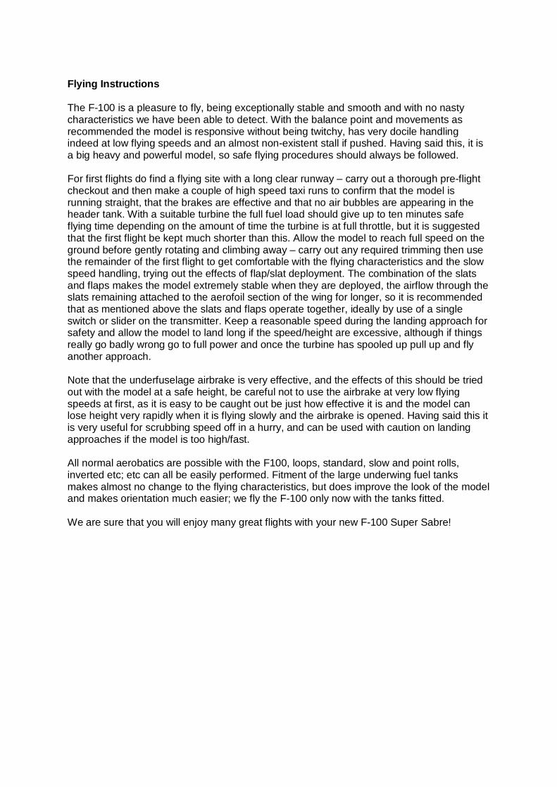
Refit the turbine and add any equipment that is to be installed under the main hatch – note that as the F-100 has such a long nose it may be necessary to mount much of the on-board equipment further back than might have been expected to avoid the need for tail weight to get the model to balance correctly.
Fit the supplied air ducting as required, cutting it down to suitable length to allow for installation. Continue the installation of the remaining on-board equipment, the prototype used a Robbe PSS2018 twin receiver/battery system being powered by 6.6v 3000mAh Li-Fe batteries. Note the use of a MAP header tank to ensure a consistent and bubble free supply of fuel to the turbine.

Balance Point and Movements

Balance Point: At a point 280mm back from the front of the turbine hatch recess as shown. (With full header tank if used).
Aileron: 30mm each way at root of aileron (25% Expo) Tailplane: 50mm each way at leading edge root of tailplane. Rudder: 50mm each way. Flap: 40mm deflection at root for take-off, 100mm for landing (minimum!) Slat: 25mm movement at root, with movement at tip proportional to this. Note that we programmed the slats to deploy whenever the flaps were lowered and in a similar proportion, so that the slats have a small amount of movement when take-off flap is selected, but full movement when full flap is used. Tailplane Neutral Point: Leading edge of tailplane to be 35mm below adjacent panel line as shown.
Flying Instructions The F-100 is a pleasure to fly, being exceptionally stable and smooth and with no nasty characteristics we have been able to detect. With the balance point and movements as recommended the model is responsive without being twitchy, has very docile handling indeed at low flying speeds and an almost non-existent stall if pushed. Having said this, it is a big heavy and powerful model, so safe flying procedures should always be followed. For first flights do find a flying site with a long clear runway – carry out a thorough pre-flight checkout and then make a couple of high speed taxi runs to confirm that the model is running straight, that the brakes are effective and that no air bubbles are appearing in the header tank. With a suitable turbine the full fuel load should give up to ten minutes safe flying time depending on the amount of time the turbine is at full throttle, but it is suggested that the first flight be kept much shorter than this. Allow the model to reach full speed on the ground before gently rotating and climbing away – carry out any required trimming then use the remainder of the first flight to get comfortable with the flying characteristics and the slow speed handling, trying out the effects of flap/slat deployment. The combination of the slats and flaps makes the model extremely stable when they are deployed, the airflow through the slats remaining attached to the aerofoil section of the wing for longer, so it is recommended that as mentioned above the slats and flaps operate together, ideally by use of a single switch or slider on the transmitter. Keep a reasonable speed during the landing approach for safety and allow the model to land long if the speed/height are excessive, although if things really go badly wrong go to full power and once the turbine has spooled up pull up and fly another approach. Note that the underfuselage airbrake is very effective, and the effects of this should be tried out with the model at a safe height, be careful not to use the airbrake at very low flying speeds at first, as it is easy to be caught out be just how effective it is and the model can lose height very rapidly when it is flying slowly and the airbrake is opened. Having said this it is very useful for scrubbing speed off in a hurry, and can be used with caution on landing approaches if the model is too high/fast. All normal aerobatics are possible with the F100, loops, standard, slow and point rolls, inverted etc; etc can all be easily performed. Fitment of the large underwing fuel tanks makes almost no change to the flying characteristics, but does improve the look of the model and makes orientation much easier; we fly the F-100 only now with the tanks fitted. We are sure that you will enjoy many great flights with your new F-100 Super Sabre!