
Feeder Protection Relay Operation Manual - ABB Group · · 2015-04-20Document symbols and...
120
Operation Manual Feeder Protection Relay REF615
Transcript of Feeder Protection Relay Operation Manual - ABB Group · · 2015-04-20Document symbols and...

Operation ManualFeeder Protection RelayREF615


Document ID: 1MRS756376Issued: 02.07.2008
Revision: CProduct version: 1.1
© Copyright 2008 - ABB. All rights reserved

CopyrightThis document and parts thereof must not be reproduced or copied without writtenpermission from ABB, and the contents thereof must not be imparted to a third party,nor used for any unauthorized purpose.
The software or hardware described in this document is furnished under a license andmay be used, copied, or disclosed only in accordance with the terms of such license.
TrademarksABB is a registered trademark of ABB Group. All other brand or product namesmentioned in this document may be trademarks or registered trademarks of theirrespective holders.
GuaranteePlease inquire about the terms of guarantee from your nearest ABB representative.
ABB Oy
Distribution Automation
P.O. Box 699
FI-65101 Vaasa, Finland
Telephone: +358 10 2211
Facsimile: +358 10 22 41094
http://www.abb.com/substationautomation

DisclaimerThe data, examples and diagrams in this manual are included solely for the conceptor product description and are not to be deemed as a statement of guaranteedproperties. All persons responsible for applying the equipment addressed in thismanual must satisfy themselves that each intended application is suitable andacceptable, including that any applicable safety or other operational requirements arecomplied with. In particular, any risks in applications where a system failure and/orproduct failure would create a risk for harm to property or persons (including but notlimited to personal injuries or death) shall be the sole responsibility of the person orentity applying the equipment, and those so responsible are hereby requested to ensurethat all measures are taken to exclude or mitigate such risks.
This document has been carefully checked by ABB but deviations cannot becompletely ruled out. In case any errors are detected, the reader is kindly requestedto notify the manufacturer. Other than under explicit contractual commitments, in noevent shall ABB be responsible or liable for any loss or damage resulting from theuse of this manual or the application of the equipment.

ConformityThis product complies with the directive of the Council of the European Communitieson the approximation of the laws of the Member States relating to electromagneticcompatibility (EMC Council Directive 2004/108/EC) and concerning electricalequipment for use within specified voltage limits (Low-voltage directive 2006/95/EC). This conformity is the result of a test conducted by ABB in accordance withArticle 10 of the directive in agreement with the product standards EN 50263 and EN60255-26 for the EMC directive, and with the product standards EN 60255-6 and EN60255-27 for the low voltage directive. The IED is designed in accordance with theinternational standards of the IEC 60255 series.

Safety information
Dangerous voltages can occur on the connectors, even though the auxiliaryvoltage has been disconnected.
Non-observance can result in death, personal injury or substantial propertydamage.
Only a competent electrician is allowed to carry out the electrical installation.
National and local electrical safety regulations must always be followed.
The frame of the device has to be carefully earthed.
When the plug-in unit has been detached from the case, do not touch theinside of the case. The relay case internals may contain high voltage potentialand touching these may cause personal injury.
The device contains components which are sensitive to electrostaticdischarge. Unnecessary touching of electronic components must thereforebe avoided.


Table of contents
Section 1 Introduction.......................................................................7This manual........................................................................................7Intended audience..............................................................................7Product documentation.......................................................................8
Product documentation set............................................................8Document revision history.............................................................9Related documentation................................................................10
Document symbols and conventions................................................10Safety indication symbols............................................................10Document conventions................................................................11Functions, codes and symbols....................................................11
Section 2 Environmental aspects...................................................13Sustainable development.................................................................13Disposing of the IED.........................................................................13
Section 3 REF615 overview...........................................................15Overview...........................................................................................15Product version history.....................................................................15Operation functionality......................................................................16
Standard configurations...............................................................16Optional functions........................................................................17
Physical hardware............................................................................18LHMI.................................................................................................19
LCD.............................................................................................20LEDs............................................................................................21Keypad........................................................................................21LHMI functionality........................................................................23
Protection and alarm indication..............................................23Parameter management ........................................................25Front communication..............................................................25
WHMI................................................................................................25Command buttons.......................................................................26
Authorization.....................................................................................27Communication.................................................................................28PCM600 configuration tool...............................................................29
Connectivity packages.................................................................29PCM600 and IED connectivity package version..........................30
Section 4 Using HMI locally or via web interface...........................31
Table of contents
REF615 1Operation Manual

Using LHMI.......................................................................................31Logging in....................................................................................31Logging out..................................................................................32Turning display backlight on........................................................33Selecting local or remote use......................................................33Identifying the device...................................................................34Adjusting display contrast............................................................34Changing LHMI language............................................................35Changing display symbols...........................................................35Navigating in the menu................................................................36
Menu structure.......................................................................36Scrolling the LCD view...........................................................36Changing the default view......................................................37
Browsing setting values...............................................................37Editing values..............................................................................38
Editing numerical values........................................................38Editing string values...............................................................39Editing enumerated values.....................................................39
Committing settings.....................................................................39Clearing and acknowledging.......................................................40Using LHMI help..........................................................................41
Using WHMI.....................................................................................41Logging in....................................................................................41Logging out..................................................................................42Identifying the device...................................................................43Navigating in the menu................................................................44
Menu structure.......................................................................45Showing all parameters...............................................................45Editing values..............................................................................47Committing settings.....................................................................49Clearing and acknowledging.......................................................51Selecting alarm view....................................................................53Selecting event view....................................................................54Selecting phasor diagrams..........................................................55Using WHMI help.........................................................................59
Section 5 IED operation ................................................................61Operation in normal case.................................................................61
Function settings.........................................................................61Test data .....................................................................................61
Disturbance case operation..............................................................61Disturbance case identification....................................................62Operation in tripping case ...........................................................62Internal IED errors.......................................................................62
Table of contents
2 REF615Operation Manual

Disturbance recording triggering.................................................63Disturbance record analysis........................................................63Disturbance reports.....................................................................63
Fault determination...........................................................................64Application problem verification...................................................64
IED parametrization..........................................................................64IED settings for IED functionality.................................................64IED settings for different operating conditions.............................65
Section 6 Operating procedures.....................................................67Monitoring.........................................................................................67
Indications...................................................................................67Monitoring indication messages.............................................67Monitoring internal IED fault ..................................................67Monitoring condition monitoring data.....................................68
Measured and calculated values.................................................68Measured values....................................................................68Using LHMI for monitoring......................................................69
Recorded data.............................................................................69Creating disturbance recordings............................................69Monitoring disturbance recorder data.....................................70Controlling and uploading disturbance recorder data.............70Monitoring fault records..........................................................71Monitoring events...................................................................71
Remote monitoring......................................................................71Operating IED remotely..........................................................72
Controlling........................................................................................72Controlling circuit breakers and disconnectors............................72
Resetting IED...................................................................................73Clearing and acknowledging via LHMI........................................73
Changing IED functionality...............................................................74Creating blockings.......................................................................74Selecting test mode.....................................................................74Connecting to trip and disturbance recorder functions................75Defining channel settings............................................................75Defining setting group..................................................................75
Activating a setting group.......................................................75Selecting a setting group for editing.......................................76Browsing and editing setting group values.............................77
Activating LEDs...........................................................................78
Section 7 Troubleshooting .............................................................79Fault tracing......................................................................................79
Identifying hardware errors..........................................................79
Table of contents
REF615 3Operation Manual

Identifying runtime errors.............................................................79Identifying communication errors.................................................80Checking communication LEDs...................................................80Running the display test..............................................................80
Indication messages.........................................................................81Internal faults...............................................................................81Warnings.....................................................................................83LED and display messages.........................................................84
Corrections procedures....................................................................84Rebooting software......................................................................84Setting password.........................................................................84Identifying IED application problems...........................................85
Inspecting wiring.....................................................................85Inspecting configuration connection.......................................85Sample data interruptions......................................................85
Section 8 Commissioning...............................................................87Commissioning checklist..................................................................87Checking installation.........................................................................87
Checking the power supply.........................................................87Checking CT circuits....................................................................88Checking VT circuits....................................................................88Checking binary input and output circuits....................................89
Binary input circuits................................................................89Binary output circuits..............................................................89
Authorizations...................................................................................89User authorization.......................................................................89
Using PCM600.................................................................................90Setting communication between IEDs and PCM600...................90
Communication options..........................................................91Setting communication parameters........................................91
Setting IED and communication.......................................................96Setting communication................................................................96Setting LHMI................................................................................96
Changing LHMI language.......................................................96Adjusting display contrast.......................................................97Changing display symbols......................................................97Changing the default view......................................................97Setting system time and time synchronization.......................98
Setting IED parameters...............................................................99Defining setting groups...........................................................99IED parametrization..............................................................102Configuring analog inputs.....................................................102
Testing IED operation.....................................................................102
Table of contents
4 REF615Operation Manual

Selecting test mode...................................................................102Testing digital I/O interface........................................................103Testing functions.......................................................................103Selecting internal fault test........................................................104
ABB Product Data Registration......................................................104
Section 9 Glossary.......................................................................107
Table of contents
REF615 5Operation Manual

6

Section 1 Introduction
1.1 This manual
Operation Manual contains instructions on how to operate the IED during normalservice once it has been commissioned. The manual can be used to find out how tohandle disturbances or how to view calculated and measured network data in orderto determine the cause of a fault.
1.2 Intended audience
This manual addresses the operator, who operates the IED on a daily basis.
The operator must be trained in and have a basic knowledge of how to operateprotection equipment. The manual contains terms and expressions commonly usedto describe this kind of equipment.
1MRS756376 Section 1Introduction
REF615 7Operation Manual

1.3 Product documentation
1.3.1 Product documentation set
Pla
nnin
g &
pur
chas
e
Eng
inee
ring
Inst
allin
g
Com
mis
sion
ing
Ope
ratio
n
Mai
nten
ance
Dec
omm
issi
onin
gde
inst
allin
g&
dis
posa
l
Application manual
Operation manual
Installation manual
Service manual
Engineering manual
Commissioning manual
Communication protocolmanual
Technical manual
Pla
nnin
g &
pur
chas
e
Eng
inee
ring
Inst
allin
g
Com
mis
sion
ing
Ope
ratio
n
Mai
nten
ance
Dec
omm
issi
onin
gde
inst
allin
g&
dis
posa
l
Pla
nnin
g &
pur
chas
e
Eng
inee
ring
Inst
allin
g
Com
mis
sion
ing
Ope
ratio
n
Mai
nten
ance
Dec
omm
issi
onin
gde
inst
allin
g&
dis
posa
l
Application manualApplication manual
Operation manualOperation manual
Installation manualInstallation manual
Service manualService manual
Engineering manualEngineering manual
Commissioning manualCommissioning manual
Communication protocolmanualCommunication protocolmanual
Technical manualTechnical manual
en07000220.vsd
IEC07000220 V3 EN
Engineering Manual contains instructions on how to engineer the IED products. Themanual provides instructions on how to use the different tools for IED engineering.It also includes instructions on how to handle the tool component available to readdisturbance files from the IEDs on the basis of the IEC 61850 definitions. It furtherintroduces the diagnostic tool components available for IED products and thePCM600 tool.
Installation Manual contains instructions on how to install the IED. The manualprovides procedures for mechanical and electrical installation. The chapters areorganized in the chronological order in which the protection IED should be installed.
Commissioning Manual contains instructions on how to commission the IED. Themanual can also be used as a reference during periodic testing. The manual providesprocedures for energizing and checking of external circuitry, setting andconfiguration as well as verifying settings and performing directional tests. Thechapters are organized in the chronological order in which the IED should becommissioned.
Section 1 1MRS756376Introduction
8 REF615Operation Manual

Operation Manual contains instructions on how to operate the IED during normalservice once it has been commissioned. The manual can be used to find out how tohandle disturbances or how to view calculated and measured network data in orderto determine the cause of a fault.
Service Manual contains instructions on how to service and maintain the IED. Themanual also provides procedures for de-energizing, de-commissioning and disposalof the IED.
Application Manual contains application descriptions and setting guidelines sortedper function. The manual can be used to find out when and for what purpose a typicalprotection function can be used. The manual can also be used when calculatingsettings.
Technical Manual contains application and functionality descriptions and listsfunction blocks, logic diagrams, input and output signals, setting parameters andtechnical data sorted per function. The manual can be used as a technical referenceduring the engineering phase, installation and commissioning phase, and duringnormal service.
The Communication Protocol manuals describe the different communicationprotocols supported by the IED. The manuals concentrate on vendor-specificimplementations.
The Point List Manual describes the outlook and properties of the data points specificto the IED. This manual should be used in conjunction with the correspondingCommunication Protocol Manual.
All manuals are not available yet.
1.3.2 Document revision historyDocument revision/date Product version HistoryA/20.12.2007 1.0 First release
B/08.02.2008 1.0 Content updated
C/02.07.2008 1.1 Content updated to correspondto the product version
The latest revision of the document can be downloaded from the ABBweb site http://www.abb.com/substationautomation
1MRS756376 Section 1Introduction
REF615 9Operation Manual

1.3.3 Related documentationName of the document Document IDApplication Manual 1MRS756378
Modbus Communication Protocol Manual 1MRS756468
Installation Manual 1MRS756375
Technical Manual 1MRS756377
1.4 Document symbols and conventions
1.4.1 Safety indication symbolsThis publication includes the following icons that point out safety-related conditionsor other important information:
The electrical warning icon indicates the presence of a hazard whichcould result in electrical shock.
The warning icon indicates the presence of a hazard which couldresult in personal injury.
The caution icon indicates important information or warning relatedto the concept discussed in the text. It might indicate the presence ofa hazard which could result in corruption of software or damage toequipment or property.
The information icon alerts the reader to relevant facts and conditions.
The tip icon indicates advice on, for example, how to design yourproject or how to use a certain function.
Although warning hazards are related to personal injury, it should be understood thatoperation of damaged equipment could, under certain operational conditions, resultin degraded process performance leading to personal injury or death. Therefore,comply fully with all warning and caution notices.
Section 1 1MRS756376Introduction
10 REF615Operation Manual
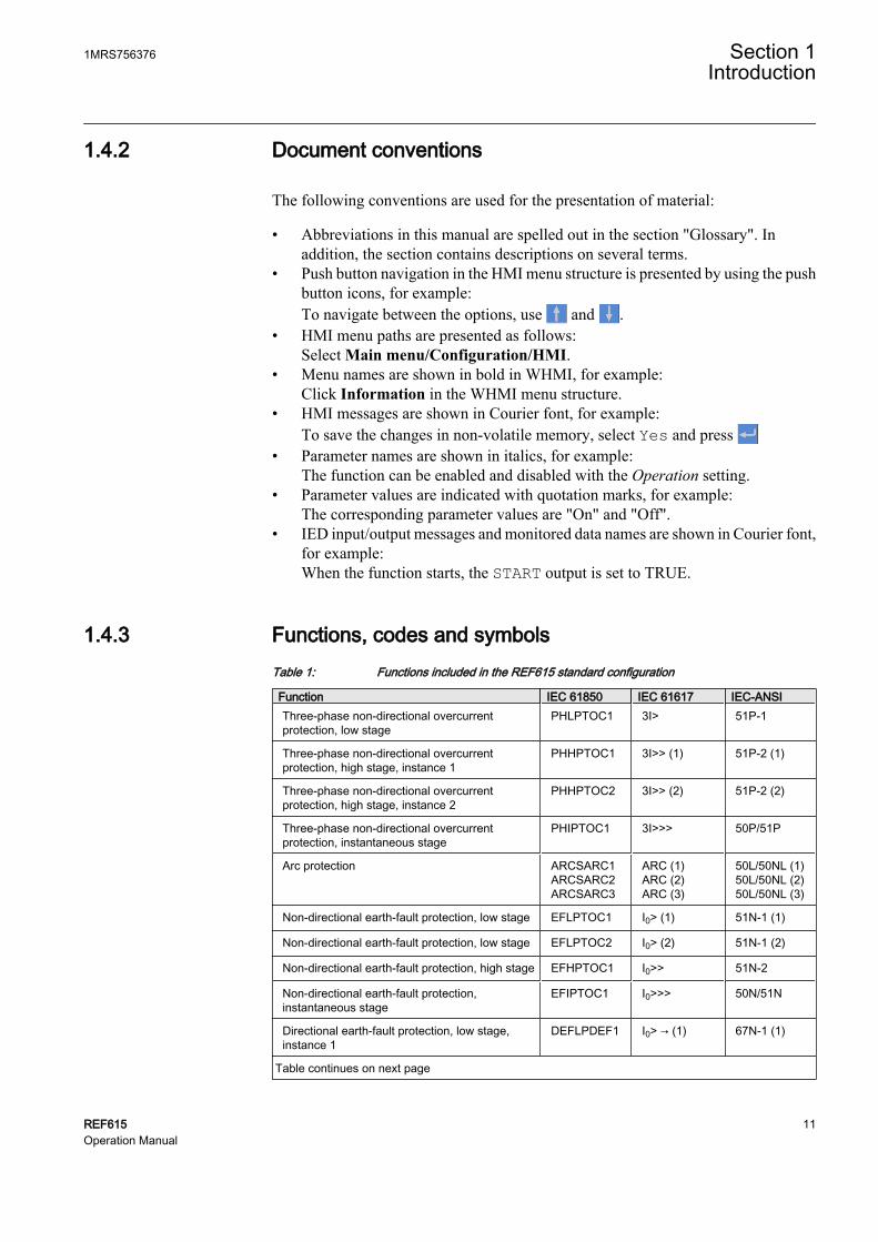
1.4.2 Document conventions
The following conventions are used for the presentation of material:
• Abbreviations in this manual are spelled out in the section "Glossary". Inaddition, the section contains descriptions on several terms.
• Push button navigation in the HMI menu structure is presented by using the pushbutton icons, for example:To navigate between the options, use and .
• HMI menu paths are presented as follows:Select Main menu/Configuration/HMI.
• Menu names are shown in bold in WHMI, for example:Click Information in the WHMI menu structure.
• HMI messages are shown in Courier font, for example:To save the changes in non-volatile memory, select Yes and press
• Parameter names are shown in italics, for example:The function can be enabled and disabled with the Operation setting.
• Parameter values are indicated with quotation marks, for example:The corresponding parameter values are "On" and "Off".
• IED input/output messages and monitored data names are shown in Courier font,for example:When the function starts, the START output is set to TRUE.
1.4.3 Functions, codes and symbolsTable 1: Functions included in the REF615 standard configuration
Function IEC 61850 IEC 61617 IEC-ANSIThree-phase non-directional overcurrentprotection, low stage
PHLPTOC1 3I> 51P-1
Three-phase non-directional overcurrentprotection, high stage, instance 1
PHHPTOC1 3I>> (1) 51P-2 (1)
Three-phase non-directional overcurrentprotection, high stage, instance 2
PHHPTOC2 3I>> (2) 51P-2 (2)
Three-phase non-directional overcurrentprotection, instantaneous stage
PHIPTOC1 3I>>> 50P/51P
Arc protection ARCSARC1ARCSARC2ARCSARC3
ARC (1)ARC (2)ARC (3)
50L/50NL (1)50L/50NL (2)50L/50NL (3)
Non-directional earth-fault protection, low stage EFLPTOC1 I0> (1) 51N-1 (1)
Non-directional earth-fault protection, low stage EFLPTOC2 I0> (2) 51N-1 (2)
Non-directional earth-fault protection, high stage EFHPTOC1 I0>> 51N-2
Non-directional earth-fault protection,instantaneous stage
EFIPTOC1 I0>>> 50N/51N
Directional earth-fault protection, low stage,instance 1
DEFLPDEF1 I0> → (1) 67N-1 (1)
Table continues on next page
1MRS756376 Section 1Introduction
REF615 11Operation Manual

Function IEC 61850 IEC 61617 IEC-ANSIDirectional earth-fault protection, low stage,instance 2
DEFLPDEF2 I0> → (2) 67N-1 (2)
Directional earth-fault protection, high stage DEFHPDEF1 I0>> → 67N-2
Transient/Intermittent earth-fault protection INTRPTEF1 I0> → IEF 67NIEF
Non-directional earth-fault protection, high stage(calculated I0 current)
EFHPTOC1 I0>> 50N-2
Negative-sequence overcurrent protection,instance 1
NSPTOC1 I2> (1) 46 (1)
Negative-sequence overcurrent protection,instance 2
NSPTOC2 I2> (2) 46 (2)
Phase discontinuity PDNSPTOC1 I2/I1> 46PD
Three-phase inrush detector INRPHAR1 3I2f> 68
Three-phase thermal protection for feeders,cables and distribution transformers
T1PTTR1 3Ith> 49F
Autoreclosure DARREC1 O → I 79
Circuit breaker failure protection CCBRBRF1 3I>/I0>BF 51BF/51NBF
Master Trip TRPPTRC1TRPPTRC2
Master Trip (1)Master Trip (2)
94/86 (1)94/86 (2)
Trip circuit supervision, instance 1 TCSSCBR1 TCS (1) TCM (1)
Trip circuit supervision, instance 2 TCSSCBR2 TCS (2) TCM (2)
Disturbance recorder RDRE1 - -
Circuit breaker condition monitoring SSCBR1 CBCM CBCM
Three-phase current measurement CMMXU1 3I 3I
Sequence current measurement CSMSQI1 I1, I2, I0 I1, I2, I0
Residual current measurement RESCMMXU1 I0 In
Residual voltage measurement RESVMMXU1 U0 Vn
Section 1 1MRS756376Introduction
12 REF615Operation Manual

Section 2 Environmental aspects
2.1 Sustainable development
Sustainability has been taken into account from the beginning of the product designincluding the pro-environmental manufacturing process, long life time, operationreliability and disposing of the IED.
The choice of the materials and the suppliers has been made according to the EURoHS directive (2002/95/EC). This directive limits the use of hazardous substanceswhich are the following:
Table 2: Maximum concentration values by weight per homogeneous material
Substance Proposed maximum concentrationLead - Pb 0,1%
Mercury - Hg 0,1%
Cadmium - Cd 0,01%
Hexavalent Chromium Cr (VI) 0,1%
Polybrominated biphenyls - PBB 0,1%
Polybrominated diphenyl ethers - PBDE 0,1%
Operational reliability and long life time have been assured with extensive testingduring the design and manufacturing processes. Moreover, long life time is supportedby maintenance and repair services as well as by the availability of spare parts.
Design and manufacturing have been done under a certified environmental system.The effectiveness of the environmental system is constantly evaluated by an externalauditing body. We follow environmental rules and regulations systematically toevaluate their effect on our products and processes.
2.2 Disposing of the IED
Definitions and regulations of hazardous materials are country-specific and changewhen the knowledge of materials increases. The materials used in this product aretypical for electric and electronic devices.
All parts used in this product are recyclable. When disposing cast-off IEDs or its parts,contact the local enterprisers who are authorized and specialized in handling
1MRS756376 Section 2Environmental aspects
REF615 13Operation Manual

electrical/electronics waste. These partners can sort the material by using dedicatedsorting processes and dispose the product according to the local requirements.
Table 3: Materials of the IED parts
IED Parts MaterialCase Metallic plates, parts and screws Steel
Plastic parts PC1), LCP2)
Electronics plug in module Various
Plug-in unit Electronics plug in modules Various
Electronics front panel module Various
Plastic parts PC, PBT3), LCP, PA4)
Metallic plate Steel
Package Box Cardboard
Attached material Manuals Paper
1) Polycarbonate2) Liquid crystal polymer3) Polybutylene terephthalate4) Polyamide
Section 2 1MRS756376Environmental aspects
14 REF615Operation Manual

Section 3 REF615 overview
3.1 Overview
REF615 is a native IEC 61850 feeder protection relay for selective short-circuit,overcurrent and earth-fault protection. It is applicable to all types of radial isolatedneutral networks, resistant earthed networks and compensated networks. REF615 ispart of a product family that will cover main protection applications for utility andindustry customers.
The IED features draw-out-type design, compact size and ease of use. Depending onthe IED variant, the protection functions may include:
• Three-phase non-directional overcurrent protection, 4 stages• Double earth-fault protection (cross-country earth-fault protection)• Non-directional earth-fault, 3 stages• Non-directional sensitive earth-fault• Directional earth-fault protection, 3 stages• Transient/intermittent earth-fault protection• Negative-phase-sequence protection, 2 stages• Phase discontinuity• Three-phase transformer inrush detector• Three-phase thermal overload, lines and cables• Circuit breaker failure protection• Electrically latched lockout relay
Depending on the IED variant, the optional functions may include:
• Auto-reclose• Arc protection, three lens sensors for arc detection
3.2 Product version history
IED version Release date Product history1.0 20.12.2007 Product released
1.1 02.07.2008 • IRIG-B• Support for parallel protocols added: IEC 61850
and Modbus• X130 BIO added: optional for variants B and D• CB interlocking functionality enhanced• TCS functionality in HW enhanced• Non-volatile memory added
1MRS756376 Section 3REF615 overview
REF615 15Operation Manual

3.3 Operation functionality
3.3.1 Standard configurationsThe IED is available with four alternative standard configurations. The table indicatesthe functions supported by the different IED configurations.
Standard configurationfunctionality
Overcurrent and directionalearth-fault protection
Overcurrent and non-directionalearth-fault protection
Std. Std. Std. Std.
conf. conf. conf. conf.
A B C D
(FE01) (FE02) (FE03) (FE04)
Protection
Three-phase non-directionalovercurrent, low-set stage ● ● ● ●
Three-phase non-directionalovercurrent, high-set stage,instance 1 ● ● ● ●
Three-phase non-directionalovercurrent, high-set stage,instance 2 ● ● ● ●
Three-phase non-directionalovercurrent, instantaneousstage ● ● ● ●
Directional earth-fault, low-setstage, instance 1 ● ● - -
Directional earth-fault, low-setstage, instance 2 ● ● - -
Directional earth-fault, high-setstage ● ● - -
Double earth-fault protection(cross-country earth-fault) ● ● - -
Transient/intermittent earth-fault ● ● - -
Non-directional earth-fault, low-set stage - - ● ●
Non-directional earth-fault, high-set stage - - ● ●
Non-directional earth-fault,instantaneous stage - - ● ●
Non-directional sensitive earth-fault - - ● ●
Negative-sequence overcurrent,instance 1 ● ● ● ●
Negative-sequence overcurrent,instance 2 ● ● ● ●
Phase discontinuity ● ● ● ●
Table continues on next page
Section 3 1MRS756376REF615 overview
16 REF615Operation Manual

Thermal overload ● ● ● ●
Circuit breaker failure protection ● ● ● ●
Three-phase inrush currentdetection ● ● ● ●
Arc protection with three sensors ○ ○ ○ ○
Control
Circuit breaker control with basicinterlocking1) ● ● ● ●
Circuit breaker control withextended interlocking2) - ● - ●
Auto-reclosing of one circuitbreaker ○ ○ ○ ○
Supervision and Monitoring
Circuit breaker conditionmonitoring - ● - ●
Trip-circuit supervision of two tripcircuits ● ● ● ●
Measurement
Transient disturbance recorder ● ● ● ●
Three-phase currentmeasurement ● ● ● ●
Current sequence components ● ● ● ●
Residual current measurement ● ● ● ●
Residual voltage measurement ● ● - -
1) Basic interlocking functionality: Closing of the circuit breaker can be enabled by a binary input signal.The actual interlocking scheme is implemented outside the relay. The binary input serves as a "masterinterlocking input" and when energized, it enables circuit breaker closing.
2) Extended interlocking functionality: The circuit breaker interlocking scheme is implemented in the relayconfiguration, based on primary equipment position information (via binary inputs) and the logicalfunctions available. The signal matrix tool of PCM600 can be used for modifying the interlockingscheme to suit the application.
● = Included,○ = Optional at the time of the order
3.3.2 Optional functionsThe optional functions available in the IED are:
• Arc protection• Auto-reclosing• Modbus TCP/IP or RTU/ASCII
1MRS756376 Section 3REF615 overview
REF615 17Operation Manual

3.4 Physical hardware
The IED consists of two main parts: plug-in unit and case. The plug-in unit contentdepends on the ordered functionality.
Table 4: Plug-in unit and case
Mainunit
Content options
Plug-in unit
HMI
CPU module
Auxiliary power/binary output module(slot X100)
48-250V DC / 100-240 V AC; or 24-60 V DC2 normally-open PO contacts1 change-over SO contacts1 normally open SO contact2 double-pole PO contacts with TCS1 dedicated internal fault output contact
AI module (slotX120) 1)
Option 1: 3 phase current inputs (1/5A)1 residual current input for non-directional earth-faultprotection (1/5A or 0.2/1A2))4 BIs
Option 2: 3 phase current inputs (1/5A)1 residual current input (1/5A or 0.2/1A)1 residual voltage input for directional earth-faultprotection (100, 110, 115 or 120 V)3 BIs
BI/O module (slotX110)
7 BIs3 SO contacts
Case Optional BI/Omodule (slot X130)
6 BIs3 SO contacts
AI module interface connectorsAuxiliary power/binary output module interface connectorsBI/O module interface connectorsCommunication module
1) The analog input module option depends on the selected standard configuration.2) The 0.2/1A input is normally used in applications requiring sensitive earth-fault protection and featuring
core-balance current transformers.
The rated input levels are selected in the IED software for phase current, residualcurrent and residual voltage. The binary input thresholds 18...176 V DC are selectedby adjusting the IED's parameter settings.
The additional BI/O module in slot X110 is included in the IED withstandard configurations B and D. The optional BI/O module in slotX130 is available for configurations B and D.
The connection diagrams of different hardware modules are presented in theApplication manual.
Section 3 1MRS756376REF615 overview
18 REF615Operation Manual

See the Installation Manual for more information about the case andthe plug-in unit.
3.5 LHMI
A070704 V2 EN
Figure 1: LHMI
The LHMI of the IED contains the following elements:
• Display• Buttons• LED indicators• Communication port
The LHMI is used for setting, monitoring and controlling.
1MRS756376 Section 3REF615 overview
REF615 19Operation Manual

3.5.1 LCDThe LHMI includes a graphical LCD that supports two character sizes. The charactersize depends on the selected language.
The amount of characters and rows fitting the view depends on the character size:
Character size Rows in view Characters on rowSmall, mono-spaced (6x12pixels)
5 rows10 rows with large screen
20
Large, variable width (13x14pixels)
4 rows8 rows with large screen
min 8
The display view is divided into four basic areas:
A070705 V2 EN
Figure 2: Display layout
1 Header
2 Icon
3 Content
4 Scroll bar (appears when needed)
• The header area at the top of the display view shows the current location in themenu structure.
• The icon area at the upper right corner of the display shows the current action oruser level.Current action is indicated by the following characters:• U: Font/Firmware is being updated• S: Parameters are being stored• !: Warning and/or indication
Current user level is indicated by the following characters:
Section 3 1MRS756376REF615 overview
20 REF615Operation Manual

• V: Viewer• O: Operator• E: Engineer• A: Administrator
• The content area with four rows shows the menu content. With larger charactersize, the content area has only three rows.
• If the menu contains more rows than the display can show at a time, a scroll barappears on the right.
The display is updated either cyclically or based on changes in the source data suchas parameters or events.
3.5.2 LEDsThe LHMI includes three protection indicators above the display: Ready, Start andTrip.
There are also 11 matrix programmable alarm LEDs on front of the LHMI. The LEDscan be configured with PCM600 and the operation mode can be selected with theLHMI.
3.5.3 KeypadThe LHMI keypad consists of push buttons which are used to navigate in differentviews or menus. With push buttons you can give open or close commands to, forexample, circuit breakers, disconnectors and switches. The push buttons are also usedto acknowledge alarms, reset indications, provide help and switch between local andremote control mode.
A070680 V3 EN
Figure 3: LHMI keypad with object control, navigation and command pushbuttons and RJ-45 communication port
1 Close
2 Open
3 Escape
4 Left
1MRS756376 Section 3REF615 overview
REF615 21Operation Manual

5 Right
6 Up
7 Down
8 Enter
9 Key
10 Clear
11 Menu
12 Remote/Local
13 Help
14 Communication port
15 Uplink LED
16 Communication LED
Object controlIf the control position of the IED is set to local with the R/L button, the IED can becontrolled using the object control buttons.
As a default, breaker 1 is always the first to be controlled. If other controllable objectsare available, the user can select them in the control menu.
Table 5: Object control push buttons
Name Description
CloseClosing the selected object.
OpenOpening the selected object.
NavigationThe arrow buttons are used for navigation. To scroll information, press the arrowbutton several times or simply keep it pressed down.
Section 3 1MRS756376REF615 overview
22 REF615Operation Manual

Table 6: Navigation push buttons
Name Description
ESC• Leaving setting mode without saving the values.• Cancelling certain actions.• Adjusting the display contrast in combination with or .• Changing the language in combination with .• Running the display test in combination with .• Deleting a character in combination with when editing a string• Inserting a space in combination with when editing a sting.
Enter• Entering parameter setting mode.• Confirming a new value of a setting parameter.
Up
Down
• Moving up and down in menus.• Scrolling active digits of a parameter when entering a new setting value.
Left
Right
• Moving left and right in menus.• Changing the active digit of a parameter when entering a new setting value.
Key• Activating the authorization procedure, when the user is not logged in.• Logging out, when the user is currently logged in.
CommandsTable 7: Command push buttons
Name Description
Menu• Moving directly to the Main Menu, if currently in default view or in any menu.• Moving to the default view, if currently in Main Menu.
R/LChanging the control position (remote or local) of the device.
• When the R LED is lit, remote control is enabled and local control disabled.• When the L LED is lit, local control is enabled and remote control disabled.• When none of the LEDs are lit, both control positions are disabled.
ClearActivating the Clear/Reset view.
HelpShowing context sensitive help messages.
3.5.4 LHMI functionality
3.5.4.1 Protection and alarm indication
Protection indicatorsProtection indicator LEDs are called Ready, Start and Trip.
1MRS756376 Section 3REF615 overview
REF615 23Operation Manual

Table 8: Ready LED
LED state DescriptionOff Auxiliary supply voltage is disconnected.
On Normal operation.
Blinking Internal fault has occurred or the IED is in test mode. Internal faults areaccompanied by an indication message.
Table 9: Start LED
LED state DescriptionOff Normal operation.
On A protection function has started and an indication message is displayed.
• If several protection functions start within a short time, the last start isindicated on the display.
Blinking A protection function is blocked.
• The blocking indication disappears when the blocking is removed orwhen the protection function is reset.
Table 10: Trip LED
LED state DescriptionOff Normal operation.
On A protection function has tripped and an indication message is displayed.
• The trip indication is latching and must be reset via communication orby pressing .
• If several protection functions trip within a short time, the last trip isindicated on the display.
Alarm indicatorsThe 11 matrix programmable LEDs are used for alarm indication.
Table 11: Alarm indications
LED state DescriptionOff Normal operation. All alarms are OFF.
On • Non-latched mode: alarm is still on.• Latched mode: alarm is still on or it is off but has not been
acknowledged.• Latched blinking mode: alarm is still on but has been acknowledged.
Blinking • Non-latched blinking mode: alarm is still on.• Latched blinking mode: alarm is still on or it is off but has not been
acknowledged.
Section 3 1MRS756376REF615 overview
24 REF615Operation Manual

3.5.4.2 Parameter management
The LHMI enables you to access the IED parameters. It is possible to read and writethree types of parameters:
• Numerical values• String values• Enumerated values
Numerical values are presented either in integer or in decimal format with minimumand maximum values. Character strings can be edited character by character.Enumerated values have a predefined set of selectable values.
3.5.4.3 Front communication
The RJ-45 port in the LHMI enables front communication. There are two LEDs abovethe communication port:
• The green uplink LED on the left is lit when the cable is successfully connectedto the port.
• The yellow communication LED on the right blinks when the IED communicateswith the connected device.
A070816 V2 EN
Figure 4: RJ-45 communication port and indication LEDs
When a computer is connected to the IED, the IED's DHCP server for the frontinterface assigns an IP address to the computer. The fixed IP address for the frontport is 192.168.0.254.
3.6 WHMI
The WHMI enables the user to access the IED via a web browser.
WHMI is disabled by default and can be enabled via the LHMI MainMenu/Configuration/HMI/Web HMI mode. You must reboot theIED for the change to take effect.
1MRS756376 Section 3REF615 overview
REF615 25Operation Manual

WHMI offers the following functions:
• Alarm indications and event lists• System supervision• Parameter settings• Measurement display• Phasor diagram
The menu tree structure on the WHMI is identical to the one on the LHMI.
A070754 V2 EN
Figure 5: Example view of the WHMI
The WHMI can be accessed:
• Locally by connecting your laptop to the IED via the front communication port.• Remotely through the Internet or over LAN/WAN.
3.6.1 Command buttonsCommand buttons can be used to edit parameters and control information via theWHMI.
Section 3 1MRS756376REF615 overview
26 REF615Operation Manual

Table 12: Command buttons
Name DescriptionPreventing automatic logout.
Enabling parameter editing.
Disabling parameter editing.
Writing parameters to the IED.
Refreshing parameter values.
Printing out parameters.
Committing changes to IED's non-volatile flash memory.
Rejecting changes.
Showing context sensitive help messages.
Clearing events.
Saving values to CSV file format.
Freezing the values so that updates are not displayed.
3.7 Authorization
The user categories have been predefined for the LHMI and the WHMI, each withdifferent rights and default passwords.
The default passwords can be changed with Administrator user rights.
User authorization is disabled by default for LHMI and can be enabledeither via the LHMI or the WHMI Main Menu/Configuration/Authorization. WHMI always requires authentication.
1MRS756376 Section 3REF615 overview
REF615 27Operation Manual
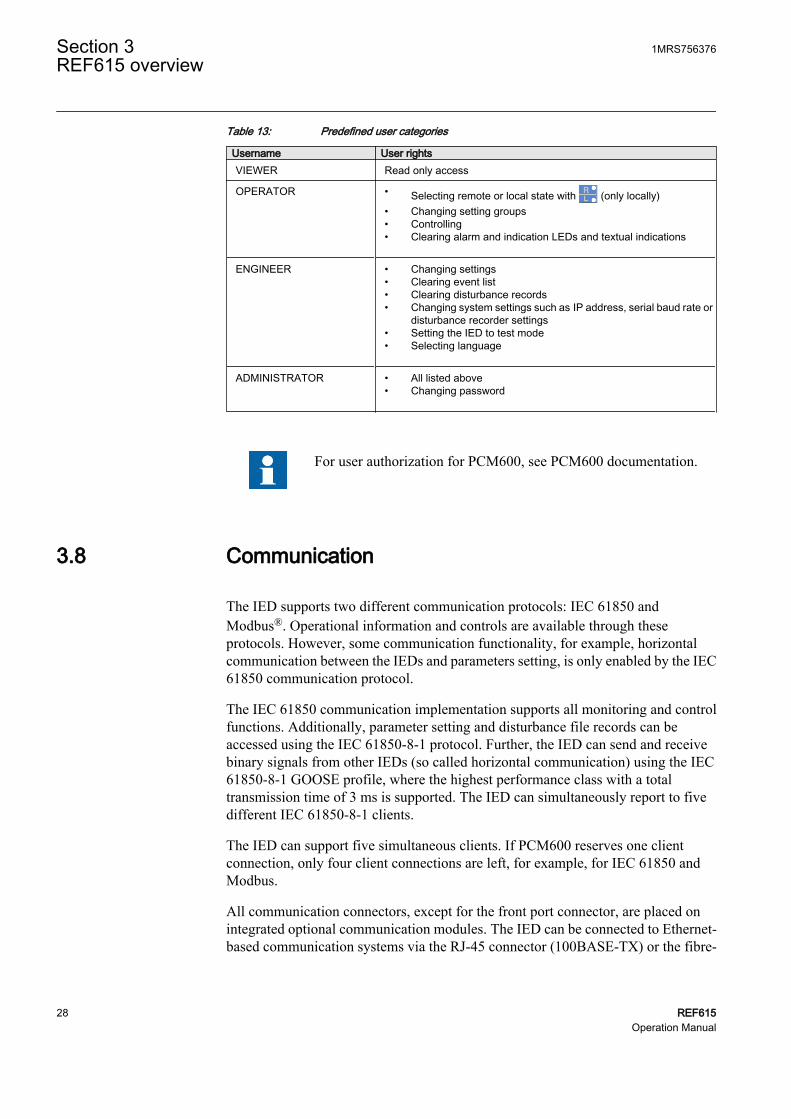
Table 13: Predefined user categories
Username User rightsVIEWER Read only access
OPERATOR • Selecting remote or local state with (only locally)• Changing setting groups• Controlling• Clearing alarm and indication LEDs and textual indications
ENGINEER • Changing settings• Clearing event list• Clearing disturbance records• Changing system settings such as IP address, serial baud rate or
disturbance recorder settings• Setting the IED to test mode• Selecting language
ADMINISTRATOR • All listed above• Changing password
For user authorization for PCM600, see PCM600 documentation.
3.8 Communication
The IED supports two different communication protocols: IEC 61850 andModbus®. Operational information and controls are available through theseprotocols. However, some communication functionality, for example, horizontalcommunication between the IEDs and parameters setting, is only enabled by the IEC61850 communication protocol.
The IEC 61850 communication implementation supports all monitoring and controlfunctions. Additionally, parameter setting and disturbance file records can beaccessed using the IEC 61850-8-1 protocol. Further, the IED can send and receivebinary signals from other IEDs (so called horizontal communication) using the IEC61850-8-1 GOOSE profile, where the highest performance class with a totaltransmission time of 3 ms is supported. The IED can simultaneously report to fivedifferent IEC 61850-8-1 clients.
The IED can support five simultaneous clients. If PCM600 reserves one clientconnection, only four client connections are left, for example, for IEC 61850 andModbus.
All communication connectors, except for the front port connector, are placed onintegrated optional communication modules. The IED can be connected to Ethernet-based communication systems via the RJ-45 connector (100BASE-TX) or the fibre-
Section 3 1MRS756376REF615 overview
28 REF615Operation Manual

optic LC connector (100BASE-FX). If connection to a RS-485 network is required,the 10-pin screw-terminal connector can be used.
3.9 PCM600 configuration tool
Protection and Control IED Manager PCM600 offers all the necessary functionalityto work throughout all stages of the IED life cycle:
• Planning• Engineering• Commissioning• Operation and disturbance handling• Functional analysis
With the individual tool components, you can perform different tasks and functionsand control the whole substation. PCM600 can operate with many different topologiesdepending on customer needs.
For more information, refer to PCM600 documentation.
3.9.1 Connectivity packagesConnectivity package is a collection of software and information related to a specificprotection and control terminal providing system products and tools to connect andinteract with the IED.
Connectivity Package Manager is a tool that helps the user to define the rightconnectivity package versions for different system products and tools. ConnectivityPackage Manager is included in products supporting the connectivity concept.
Use the connectivity packages to create configuration structure in PCM600. Inaddition to other products supporting connectivity concept, the connectivity packagesfor PCM600 contain:
• Description of IED's internal parameters and their properties such as data format,unit, setting range, visibility and access rights. The description texts can betranslated into other languages as well.
• Software components that adapt the IED-specific interfaces to the standardinterfaces of system products and tools such as IED-specific dispatchers for tools.This means that there is a protocol-specific adaptation for the parameter setting
1MRS756376 Section 3REF615 overview
REF615 29Operation Manual

and disturbance handling tool components, for example disturbance uploadingaccording to COMTRADE.
3.9.2 PCM600 and IED connectivity package versionSupported tools:
• Protection and Control IED Manager PCM600 Ver. 2.0 SP1 or later• REF615 Connectivity Package Ver. 1.2
• Parameter Setting Tool• Disturbance Handling Tool• Signal Monitoring Tool• Signal Matrix Tool• Communication Management Tool
The necessary connectivity packages can be downloaded from theABB web site http://www.abb.com/substationautomation
Section 3 1MRS756376REF615 overview
30 REF615Operation Manual

Section 4 Using HMI locally or via web interface
4.1 Using LHMI
You must be logged in and authorized to use the LHMI. Password authorization isdisabled by default and can be enabled either via the LHMI or WHMI.
To enable password authorization, select Main Menu/Configuration/Authorization/Local override. Set the parameter toFalse.
4.1.1 Logging inLog in to use the LHMI:
1. Press any key except for to activate the login procedure.2. Press or to select the user level.
A070888 V2 EN
Figure 6: Selecting access level
3. Confirm the selection with .4. Enter the prompted password digit by digit.
1MRS756376 Section 4Using HMI locally or via web interface
REF615 31Operation Manual

• Activate the digit to be entered with and .• Enter the character with and .
A070890 V2 EN
Figure 7: Entering password
5. Press to confirm the login.
• To cancel the procedure, press .
A070889 V2 EN
Figure 8: Error message indicating wrong password
The user level you are logged into shows on the LCD's upper rightcorner in the icon area.
4.1.2 Logging outThe user is automatically logged out 30 seconds after the backlight timeout.
Manual logout is also possible:
1. Press .2. To confirm logout, select Yes and press .
Section 4 1MRS756376Using HMI locally or via web interface
32 REF615Operation Manual

A070837 V2 EN
Figure 9: Logging out
• To cancel logout, press .
4.1.3 Turning display backlight onThe display backlight is normally off. It turns on during the display test at power up.
• To turn on the backlight manually, press any LHMI push button.The backlight turns on and the panel is ready for further operations.
If the panel has not been used for a predefined timeout period, the backlight isswitched off. The user is logged out from the current user level 30 seconds after thedisplay backlight has turned off.
The display returns to the default view and all unconfirmed operations such asparameter editing and breaker selection are cancelled.
You can change the backlight timeout period in Main Menu/Configuration/HMI/Backlight timeout.
4.1.4 Selecting local or remote useThe control position of the IED can be changed with the R/L button. In local positionprimary equipment, such as circuit breakers and disconnectors, can be controlled viathe LHMI. In remote position, control operations are possible only from a higherlevel, that is from a control center.
To change the IED's control position:
• Press for two seconds.
• When the L LED is lit, local control is enabled and remote control disabled.• When the R LED is lit, remote control is enabled and local control disabled.• When none of the LEDs are lit, both control positions are disabled.
The control position cannot be simultaneously local and remote,but it can be disabled when neither of the positions is active.
1MRS756376 Section 4Using HMI locally or via web interface
REF615 33Operation Manual

You must be logged in and authorized to control the IED.
4.1.5 Identifying the deviceThe IED information includes detailed information about the device, such as revisionand serial number.
The IED information is shown on the display for a few seconds when the device startsup. The same information is also found in the IED menu.
To view the device information:
1. Select Main Menu/Information.2. Select a submenu with and .
A071158 V2 EN
Figure 10: Selecting submenu
3. Enter the submenu with .4. Browse the information with and .
A071160 V2 EN
Figure 11: IED information
4.1.6 Adjusting display contrastTo obtain optimal readability, you can adjust the display contrast. The contrast canbe adjusted anywhere in the menu structure.
Section 4 1MRS756376Using HMI locally or via web interface
34 REF615Operation Manual

• To increase the contrast, press simultaneously and .• To decrease the contrast, press simultaneously and .
The selected contrast value is stored in the non-volatile memory if you are logged inand authorized to control the IED. After an auxiliary power failure, the contrast isrestored.
4.1.7 Changing LHMI languageTo change the LHMI language:
1. Select Main Menu/Language and press .2. Change the language with or .3. Press to confirm the selection.4. Commit the changes.
A071010 V2 EN
Figure 12: Changing the LHMI language
You can change the language also by pressing simultaneously and.
4.1.8 Changing display symbolsTo switch between the display symbols IEC 61850, IEC 61617 and IEC-ANSI:
1. Select Main Menu/Configuration/HMI/FB naming convention and press.
2. Change the display symbols with or .3. Press to confirm the selection.
The IED has to be rebooted if the WHMI display symbols arechanged. With the LHMI, the change takes effect immediately.
1MRS756376 Section 4Using HMI locally or via web interface
REF615 35Operation Manual

4.1.9 Navigating in the menuYou can navigate the menus and change the display views on the screen with thekeypad:
• To move to the Main Menu or default view, press .• To move up or down in a menu, press or .• To move downwards in the menu tree, press .• To move upwards in the menu tree, press .• To enter setting mode, press .• To leave setting mode without saving, press .
4.1.9.1 Menu structure
The Main Menu contains the following main groups:
• Language• Monitoring• Settings• Configuration• Tests• Information• Clear• Disturbance records• Events• Measurements
Main groups are divided further into more detailed submenus.
4.1.9.2 Scrolling the LCD view
If a menu contains more rows than the display can show at a time, a scroll bar isdisplayed on the right.
A070895 V2 EN
Figure 13: Scroll bar on the right
• To scroll the view upwards, press .• To scroll the view downwards, press .• To jump from the last row to the first row, press again.
Section 4 1MRS756376Using HMI locally or via web interface
36 REF615Operation Manual

• Press to jump from the first row to the last row.
• To scroll parameter names and values that do not fit the screen, press . Press once to return to the beginning.
4.1.9.3 Changing the default view
The default view of the display is the Measurements unless set otherwise.
To change the default view:
1. Select Main Menu/Configuration/HMI/Default view and press .2. Change the default view with or .3. Press to confirm the selection.
4.1.10 Browsing setting valuesTo browse setting values:
1. Select Main Menu/Settings/Settings and press .2. Select the setting group to be viewed with or .
A070858 V2 EN
Figure 14: Selecting a setting group
3. Press to confirm selection.4. To browse the settings, scroll the list with and and to select a setting
press . To move back to the list, press .
A070859 V2 EN
Figure 15: Setting alternatives in the selected setting group
1MRS756376 Section 4Using HMI locally or via web interface
REF615 37Operation Manual

4.1.11 Editing valuesYou must be logged in and authorized to edit values.
4.1.11.1 Editing numerical values
To edit numerical values:
1. Select Main Menu/Settings and then a setting.When you start editing numerical values, the last digit is active.• When the symbol in front of the value is ↑, you can only increase the active
value.• When the symbol is ↓ you can only decrease the active value.• When the symbol in front of the value is ↕, you can either increase or
decrease the active value.
A070755 V2 EN
Figure 16: Last digit is active and it can only be increased
2. Press to increase or to decrease the value of an active digit.One press increases or decreases the value by a certain step. For integer values,the change is 1, 10, 100 or 1000 (...) depending on the active digit. Additionally,for decimal values, the change can be fractions 0.1, 0.01, 0.001 (...) dependingon the active digit.
3. Press or to move the cursor to another digit.4. The minimum or maximum value can be set by selecting the arrow symbol in
front of the value:• To set the value to the maximum, press .• To set the value to the minimum, press .
A070756 V2 EN
Figure 17: Arrow symbol is active, the value is set to the maximum
Section 4 1MRS756376Using HMI locally or via web interface
38 REF615Operation Manual

After pressing , the previous value can be restored by pressing once, andvice versa. Another press of or sets the value to the lower or higher limit.The symbol in front of the value is ↕, when the previous value is shown.
A070757 V2 EN
Figure 18: Restoring the previous value
4.1.11.2 Editing string values
To edit string values consisting of UTF-8 characters:
1. Activate the setting mode and select a setting.When editing string values, the cursor moves to the first character.
2. Press or to change the value of an active character.One press changes the value by one step. The available UTF-8 character codesare 32...126 and 192...383.
3. Press or to move the cursor to another character.
• To insert characters or space, press simultaneously and .• To delete characters, press simultaneously and .
4.1.11.3 Editing enumerated values
To edit enumerated values:
1. Activate the setting mode and select a setting.When editing an enumerated value, the selected value is shown inverted.
2. Press or to change the value of an active enumerated value.One press changes the enumerated value by one step in the parameter specificorder.
4.1.12 Committing settingsEditable values are stored either in RAM or in non-volatile flash memory. Valuesstored in flash memory are in effect also after reboot.
Some parameters have an edit-copy. If editing is cancelled, the values with an edit-copy are immediately restored to the original value. The values without an edit-copy,
1MRS756376 Section 4Using HMI locally or via web interface
REF615 39Operation Manual

such as string values, are restored to the original value only after a reboot even thoughthe edited value is not stored in the flash memory.
To store changes into non-volatile memory:
1. Press to confirm any changes.2. Press to move upwards in the menu tree or to enter the Main Menu.3. To save the changes in non-volatile memory, select Yes and press .
A070891 V2 EN
Figure 19: Confirming settings
• To exit without saving changes, select No and press .
• If the parameter has an edit-copy, the original parameter value isrestored.
• If the parameter does not have an edit-copy, the edited parametervalue remains visible until you reboot the IED. However, the editedvalue is not stored in non-volatile memory and the reboot restoresthe original value.
• To cancel saving settings, select Cancel and press . The value returnsto editing mode.
After certain parameters are changed, the IED has to be restarted.
4.1.13 Clearing and acknowledgingYou can reset, acknowledge or clear all messages and indications, including LEDsand latched outputs as well as registers and recordings, with the Clear button. Pressingthe Clear button activates a selection menu, where you can choose which clearanceor reset function you want to make. Events and alarms assigned to alarm LEDs arecleared with the Clear button as well.
To clear, reset or acknowledge messages and indications:
1. Press to activate the Clear view.
Section 4 1MRS756376Using HMI locally or via web interface
40 REF615Operation Manual

A070860 V2 EN
Figure 20: Clear view
2. Select the item to be cleared with or .3. Press , change the value from False to True with or and press
again.The item is now cleared and the value changes back to False.
4. Repeat steps 2 and 3 to clear other items.
4.1.14 Using LHMI helpThe LHMI help is used to get information from, for example, the selected view, menuor a single parameter.
To open the context sensitive help:
1. Press .The help view is displayed.
2. If the help text exceeds the display area, scroll the text with or .3. To close the help, press .
4.2 Using WHMI
WHMI is disabled by default. To use it, you must enable it via the LHMI in MainMenu/Configuration/HMI/Web HMI mode. You must reboot the IED for thechange to take effect.
You must be logged in and authorized to use the WHMI.
Using favorites in a web browser is not recommended. If you are unauthorized andselect a favorite pointing to a WHMI page, you are redirected to the log in page. Withauthorization you are redirected to the startup page.
4.2.1 Logging inLog in to use the WHMI:
1MRS756376 Section 4Using HMI locally or via web interface
REF615 41Operation Manual

1. Enter the username with capital letters.2. Enter the password.3. Click Log in.
A070923 V2 EN
Figure 21: Entering username and password to use the WHMI
4.2.2 Logging outThe user is logged out after session timeout. The timeout can be set in Main Menu/Configuration/HMI/Web HMI timeout. The red session timeout bar appears oneminute before the timeout expires. You can prevent automatic logout by clickingClose this dialog.
A070933 V2 EN
Figure 22: Session timeout
Section 4 1MRS756376Using HMI locally or via web interface
42 REF615Operation Manual

• To log out manually, click Logout on the menu bar.
A070924 V2 EN
Figure 23: WHMI logout
4.2.3 Identifying the deviceThe IED information includes detailed information about the device, such as revisionand serial number.
To view the device information:
1MRS756376 Section 4Using HMI locally or via web interface
REF615 43Operation Manual

1. Click Information in the WHMI menu structure.2. Click a submenu to see the data.
A070925 V2 EN
Figure 24: Device information
4.2.4 Navigating in the menuThe menu tree structure on the WHMI is identical to the one on the LHMI.
In the menu bar:
• The General view shows the IED version and status.• The Events view contains a list of events produced by the application
configuration.• The Alarms view shows the status of alarm LEDs.• The Phasor diagrams view shows phasor diagrams.• The Parameter list view shows all parameters.• The WHMI settings view contains user settings for the client, that is the web
browser. WHMI settings include, for example, the client-specific setting for theWHMI language. Different users can use different languages when connectingto the same IED. The WHMI language selection is independent of the languageselection for the LHMI.
• Logout ends the session.
Section 4 1MRS756376Using HMI locally or via web interface
44 REF615Operation Manual

A070945 V2 EN
Figure 25: Navigating in the WHMI menus
4.2.4.1 Menu structure
The Main Menu contains the following main groups:
• Language• Monitoring• Settings• Configuration• Tests• Information• Clear• Disturbance records• Events• Measurements
Main groups are divided further into more detailed submenus.
4.2.5 Showing all parametersTo view all parameters:
1. Click Parameter list in the menu bar.
1MRS756376 Section 4Using HMI locally or via web interface
REF615 45Operation Manual
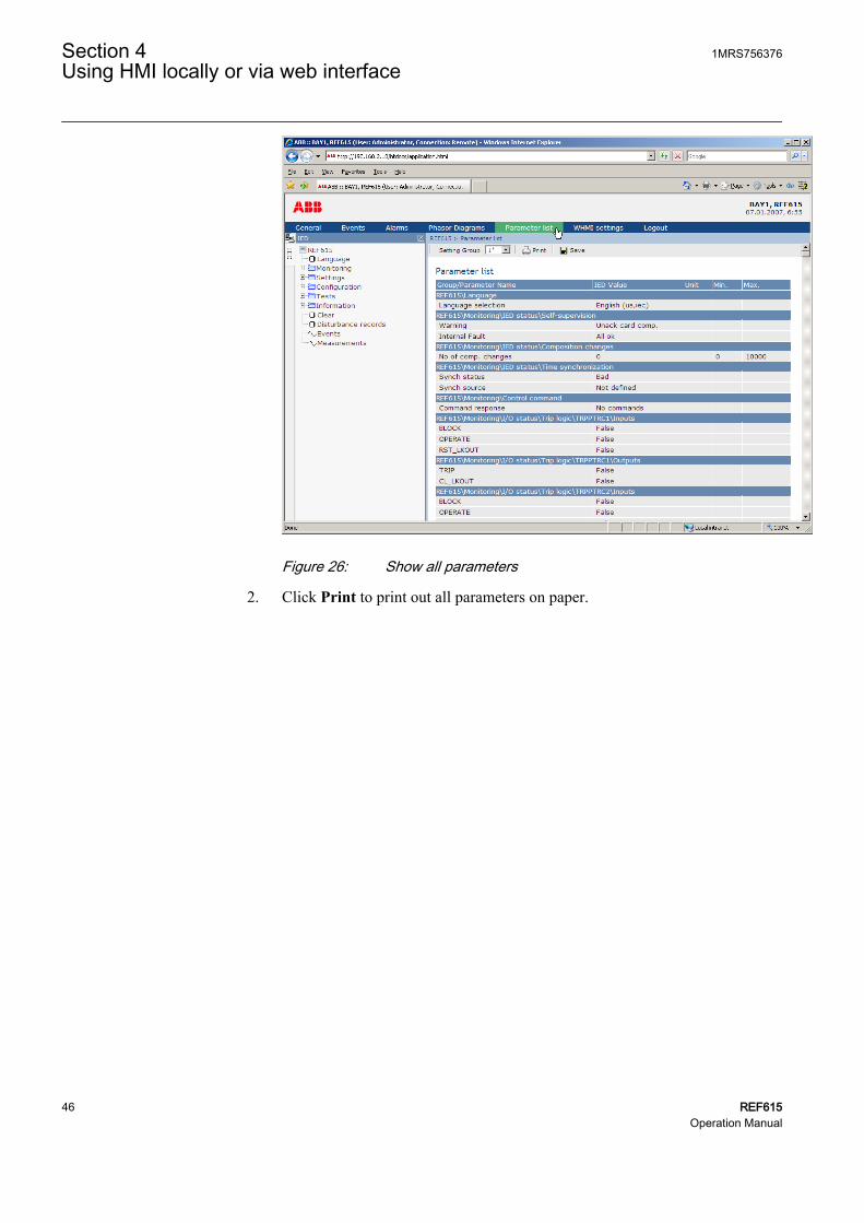
A070963 V2 EN
Figure 26: Show all parameters
2. Click Print to print out all parameters on paper.
Section 4 1MRS756376Using HMI locally or via web interface
46 REF615Operation Manual

A071008 V2 EN
Figure 27: All parameters listed
3. Click Save to save all parameters in CSV file format.
4.2.6 Editing valuesTo edit values via the WHMI:
1. Click the menu in the WHMI tree.2. Click the submenu to see function blocks.3. Click a function block to see the setting values.4. Click Enable Write.
Some parameters, for example the IED test mode, cannot be setvia the WHMI.
1MRS756376 Section 4Using HMI locally or via web interface
REF615 47Operation Manual

A070929 V2 EN
Figure 28: Enable writing to edit a value
The selected setting group is shown in the Setting Group drop-down box. Theactive setting group is indicated with an asterisk *.
5. Edit the value.• The minimum and maximum values for a parameter are shown in the Min.
and Max. columns.• Setting group values are indicated with .
A070930 V2 EN
Figure 29: Editing value
• If the entered value is within the accepted value range, the selection ishighlighted in green. If the value is out of range, the row is highlighted inred and a warning dialog box appears.
Section 4 1MRS756376Using HMI locally or via web interface
48 REF615Operation Manual

A070934 V2 EN
Figure 30: Warning indicating that the entered value is incorrect
• If writing values fails, a warning dialog box appears.
GUID-E10EE091-CFB9-4278-9FA4-7340C26F5814 V2 EN
Figure 31: Warning indicating that the values were not written to theIED
If you accidentally click Enable Write, click Disable Write.However, Disable Write is not selectable if some value has alreadybeen written to the IED. If Write to IED has been clicked, you canonly Commit or Reject.
4.2.7 Committing settingsEditable values are stored either in RAM or in non-volatile flash memory. Valuesstored in flash memory are in effect also after reboot.
Some parameters have an edit-copy. If editing is cancelled, the values with an edit-copy are immediately restored to the original value. The values without an edit-copy,such as string values, are restored to the original value only after a reboot even thoughthe edited value is not stored in the flash memory.
To store changes into non-volatile memory:
1. Click Write to IED after editing parameter values to put the values into IED'sdatabase for use.
1MRS756376 Section 4Using HMI locally or via web interface
REF615 49Operation Manual

A070931 V2 EN
Figure 32: Writing values to IED
The values are not stored to the flash memory.2. Click Commit to write the values to the flash memory.
• Click Reject to cancel saving settings.• If the parameter has an edit-copy, the original parameter value is
restored.• If the parameter does not have an edit-copy, the edited parameter
value remains visible until you reboot the IED. However, the edited
Section 4 1MRS756376Using HMI locally or via web interface
50 REF615Operation Manual

value is not stored in non-volatile memory and thus the rebootrestores the original value.
A070932 V2 EN
Figure 33: Committing changes
Committing values will take a few seconds.
If you only write values to the IED and then reboot, the old valueswill resume in the IED as active values and the new values are lost.
4.2.8 Clearing and acknowledgingYou can reset, acknowledge or clear all messages and indications, including LEDsand latched outputs as well as registers and recordings, in the Clear menu.
To clear, reset or acknowledge messages and indications:
1. Click the Clear menu.
1MRS756376 Section 4Using HMI locally or via web interface
REF615 51Operation Manual

A070935 V2 EN
Figure 34: Selecting clear menu
2. Click Enable write.3. In the New Value box, click True to select the item to be cleared.4. Click Write to IED.5. Click Reject.
Section 4 1MRS756376Using HMI locally or via web interface
52 REF615Operation Manual

A070936 V2 EN
Figure 35: Clearing indications and LEDs
4.2.9 Selecting alarm viewAlarm view shows the status of alarm LEDs. These are the same LEDs that are locatedon the upper right side of the LHMI panel.
To monitor the alarms:
• Click Alarms in the menu bar.
1MRS756376 Section 4Using HMI locally or via web interface
REF615 53Operation Manual

A070946 V2 EN
Figure 36: Monitoring alarms
4.2.10 Selecting event viewThe event view contains a list of events produced by the application configuration.
To monitor the events:
1. Click Events in the menu bar.
Section 4 1MRS756376Using HMI locally or via web interface
54 REF615Operation Manual

A070947 V2 EN
Figure 37: Monitoring events
2. Click Save to save the events in CSV file format.The CSV file can be opened with a spreadsheet program such as OpenOffice.orgCalc or Microsoft Excel.
3. Click Clear events to clear all events from the IED.
4.2.11 Selecting phasor diagramsTo view phasor diagrams:
1. Click Phasor diagrams in the menu bar.
1MRS756376 Section 4Using HMI locally or via web interface
REF615 55Operation Manual

A070948 V2 EN
Figure 38: Normal case with symmetrical phase currents
2. Toggle the diagram visibility by selecting it from the drop-down menu.
Section 4 1MRS756376Using HMI locally or via web interface
56 REF615Operation Manual

GUID-5F3C9CC8-1AE8-4235-836F-AC93E1E73708 V2 EN
Figure 39: Toggling the diagram visibility
Visible diagrams are indicated with an asterisk *.3. Change the size of the diagram by changing the zoom value.
1MRS756376 Section 4Using HMI locally or via web interface
REF615 57Operation Manual

GUID-690A11A9-FEC4-4558-A68F-16FBAC500E3B V2 EN
Figure 40: Zooming the diagram
4. Click Freeze to stop updating the phasor diagram.No updates will appear in the diagram. No updates will appear in the diagram.
Section 4 1MRS756376Using HMI locally or via web interface
58 REF615Operation Manual

A071226 V2 EN
Figure 41: The arrow extends outside the circle if the current value is toohigh
An SVG plugin is needed to view phasor diagrams.
4.2.12 Using WHMI helpWith the WHMI help you can get information from, for example, a single parameter.
To open the context sensitive help:
1. Click .The help dialog box is displayed.
1MRS756376 Section 4Using HMI locally or via web interface
REF615 59Operation Manual

A070927 V2 EN
Figure 42: Clicking the help button
2. To close the help dialog box, click OK.
Section 4 1MRS756376Using HMI locally or via web interface
60 REF615Operation Manual

Section 5 IED operation
5.1 Operation in normal case
The basic operation procedures in normal IED use situation are:
• Monitoring of measured values• Checking the function setting parameters• Checking the test data
All basic operations can be performed via the LHMI, WHMI or with PCM600.
For more information, refer to PCM600 documentation.
5.1.1 Function settingsTo check the correct operation of the IED, check the function settings via theLHMI, WHMI or PCM600.
5.1.2 Test dataThe IED's functions can be tested to ensure correct operation. After a specific test,you can analyze the results.
5.2 Disturbance case operation
The IED is designed to identify and indicate several types of disturbances. The mainpurpose of a protective IED is to identify power system disturbances and operateaccording to the disturbance to avoid damage for power system equipment and people.In other words, to disconnect the disturbance from the healthy network.
Many disturbance origins are permanent and cannot be automatically cleared. TheIED then collects disturbance data for later analysis.
Only authorized and skilled personnel should analyze possible errorsand decide on further action. Otherwise, stored important disturbancedata can be permanently lost
1MRS756376 Section 5IED operation
REF615 61Operation Manual

Some disturbances can be IED related, for example, external damage to hardware.The IED supervises internal faults and indicates them to ensure that the user can takethe right corrective actions. Disturbance data can be read, managed and analyzed withPCM600.
For more information, refer to PCM600 documentation.
5.2.1 Disturbance case identificationDisturbances and their causes can be identified on the basis of indicator LEDs: Ready,Start and Trip. In normal operation case the Ready LED is steady green.
Table 14: Disturbance indications
LED State DescriptionStart LED Yellow, steady Protection started
Start LED Yellow, blinking Protection function blocked
Trip LED Red, steady Protections operated
Ready LED Green, blinking Internal faults
Further actions to be taken to identify the disturbance:
• Analyzing disturbance recordings• Monitoring recorded data• Reading internal events• Finding available functions
5.2.2 Operation in tripping caseIf a protection function trip is not cleared automatically, the cause of fault should bechecked to identify needs for further actions.
Document the tripping case before clearing the information from theIED.
5.2.3 Internal IED errorsThe IED monitors internal software and hardware errors. Internal error informationis collected to the IED for later analysis. The main indication of an internal fault is ablinking green Ready LED.
Section 5 1MRS756376IED operation
62 REF615Operation Manual

Errors can be caused by external or internal events damaging the IED. Internalsupervision functionality monitors different types of internal errors. These can bedivided to hardware errors, runtime errors in application or operating system andcommunication errors. Further actions always depend on the cause of the errors.
Only authorized and skilled personnel should analyze the errors anddecide on further actions.
Internal IED errors may be caused by:
• Hardware errors• Runtime errors• Communication errors
The IED records:
• IED self-supervision report• Event list• System registrations
Document all the recorded data from the IED before you reset thetripping and IED lockout functions.
5.2.4 Disturbance recording triggeringDisturbance recordings are normally triggered by IED applications when they detectfault events. Disturbance recordings can also be triggered manually or periodically.
5.2.5 Disturbance record analysisThe IED collects disturbance records of fault events which are set to trigger thedisturbance recorder. Disturbance data is collected and stored for later viewing andanalysis. The disturbance recorder data can be uploaded and analyzed, for example,with PCM600.
For more information, see PCM600 documentation.
5.2.6 Disturbance reportsPCM600 can be used for creating reports of disturbance recorder data.
1MRS756376 Section 5IED operation
REF615 63Operation Manual

For more information, see PCM600 documentation.
5.3 Fault determination
Sometimes the cause of an application fault can be determined via the LHMI. Usually,this is not enough and a more detailed analysis of the application configuration isneeded. This can be done with PCM600.
5.3.1 Application problem verificationThe faulty operation of application functions is usually related to wrong configurationor incorrect wiring of the external voltage and currents or binary inputs.
5.4 IED parametrization
IED parameters are usually set with a parameter setting tool but it can also be donevia the LHMI or WHMI.
Setting parameters need to be calculated according to the electrical networkconditions and the electrical characteristics of the protected equipment. The IED'ssettings need to be verified before the IED is connected to a system.
For more information, see PCM600 documentation.
Document all changes to parameter settings.
5.4.1 IED settings for IED functionalityFunction settings can be edited one by one by navigating to the individual settingvalues, for example via the LHMI. The values in other setting groups should be knownbefore editing a certain setting value.
After completing the editing of setting group values, the new values are activated.The user can either commit the edited values or discard them. Setting values can alsobe copied from one setting group to another.
Section 5 1MRS756376IED operation
64 REF615Operation Manual

5.4.2 IED settings for different operating conditionsIED settings can be designed for various operation conditions by defining differentsetting values to different setting groups. The active setting group can be changed bythe IED application or manually via the LHMI.
1MRS756376 Section 5IED operation
REF615 65Operation Manual

66

Section 6 Operating procedures
6.1 Monitoring
6.1.1 IndicationsThe operation of the IED can be monitored via three different indications on theLHMI:
• Three indicator LEDs with fixed functionality: Ready, Start and Trip• 11 programmable alarm LEDs• A text message on the display
6.1.1.1 Monitoring indication messages
Indication messages and tripping data are shown in a dialog box.
To monitor indication messages:
1. Read the indication message in the dialog box.The message can indicate the starting or tripping of protection functions or aninternal fault in the device.
2. Press to close the indication message without clearing it or press toactivate the Clear view and to clear messages.
A071264 V2 EN
Figure 43: Indication message
6.1.1.2 Monitoring internal IED fault
The blinking green LED indicates an internal IED fault. Internal IED fault messagesare shown in a dialog box.
1MRS756376 Section 6Operating procedures
REF615 67Operation Manual

A071144 V2 EN
Figure 44: Fault indication
To monitor the latest fault indication:
1. Select Main Menu/Monitoring/IED status/Self-supervision.2. Press or to scroll the view.
All internal IED fault messages are collected in C:\userlog.txt. The log filecan be uploaded and viewed by the user. The timestamp of the fault is included in thelog file.
6.1.1.3 Monitoring condition monitoring data
To access condition monitoring related data:
1. Select Main Menu/Monitoring/I/O status/Condition monitoring.2. Press or to scroll the view.
With PCM600 the user can map output signals from condition monitoring relatedfunction blocks to the appropriate destinations.
6.1.2 Measured and calculated valuesMeasurement view in Main Menu/Measurements shows the momentary actualvalues for various power system measurements.
All values show the momentary measurement value and some include also demandvalues calculated from set period.
6.1.2.1 Measured values
Measured values can be accessed through the LHMI or WHMI.
Table 15: Measured values
Indicator DescriptionIL1-A Current measured on phase L1
IL2-A Current measured on phase L2
IL3-A Current measured on phase L3
IL1-dem-A Current demand value on phase L1
Table continues on next page
Section 6 1MRS756376Operating procedures
68 REF615Operation Manual

Indicator DescriptionIL2-dem-A Current demand value on phase L2
IL3-dem-A Current demand value on phase L3
I0-A Measured earth-fault current
Ng-Seq-A Negative phase sequence
Ps-Seq-A Positive phase sequence
Zro-Seq-A Zero phase sequence
U0-kV Measured residual voltage
6.1.2.2 Using LHMI for monitoring
To monitor measured and calculated values:
1. Select Main Menu/Measurements.The list of IED's basic measurements is shown.
2. Scroll the view with and .
6.1.3 Recorded dataThe IED is provided with intelligent and flexible functionality which collects differentkinds of data, for example, in case of fault event. The data gives substantialinformation for the post fault analysis. These data include:
• Disturbance records• Fault records• Events
6.1.3.1 Creating disturbance recordings
Normally disturbance recordings are triggered by the IED applications.
To trigger a disturbance recording manually:
1. Select Main Menu/Disturbance records.2. Select Trig recording with or .3. Press , change the value from False to True with or and press
again. The disturbance recorder is now triggered.
1MRS756376 Section 6Operating procedures
REF615 69Operation Manual

A070861 V2 EN
Figure 45: Changing the value
6.1.3.2 Monitoring disturbance recorder data
Individual disturbance recordings must be uploaded from the IED with appropriatesoftware such as PCM600 to monitor disturbance recorder data. All disturbancerecordings can be found from the C:\COMTRADE directory.
To monitor the state of the disturbance recorder via the LHMI:
1. Select Main Menu/Disturbance records.2. All the disturbance recorder information is listed. To view the following items,
scroll the list with or :
• Number of recordings currently in IED memory• Remaining amount of recordings that can fit into the available recording
memory• Recording memory used in percentage value• If the periodic triggering functionality is used, the time to trigger which
indicates the remaining time to next periodic triggering of the disturbancerecorder.
A070863 V2 EN
Figure 46: Monitoring disturbance recorder via the LHMI
6.1.3.3 Controlling and uploading disturbance recorder data
Disturbance recorder data can be controlled and read with PCM600.
For more information, see PCM600 documentation.
Section 6 1MRS756376Operating procedures
70 REF615Operation Manual

6.1.3.4 Monitoring fault records
To monitor fault records:
1. Select Main Menu/Monitoring/Recorded data.2. To navigate between the fault records, press and .3. To enter or exit a submenu, press or .
A071146 V2 EN
Figure 47: Monitoring fault records
6.1.3.5 Monitoring events
Event view contains a list of events produced by the application configuration. Eachevent takes one view area. The header area shows the currently viewed event indexand the total amount of the events. The most recent event is always first.
To monitor events:
1. Select Main Menu/Events.2. Press to view the first event.
Date, time, device description, object description and event text elements of theevent are shown.
3. Press or to scroll the view.
A071148 V2 EN
Figure 48: Monitoring events
6.1.4 Remote monitoringThe IED supports comprehensive remote monitoring.
1MRS756376 Section 6Operating procedures
REF615 71Operation Manual

6.1.4.1 Operating IED remotely
With the PCM600 tool you can:
• Read maintenance record and version log• Analyze disturbance record data• Create disturbance record• Read IED values.
For more information, refer to PCM600 documentation.
6.2 Controlling
6.2.1 Controlling circuit breakers and disconnectorsThe primary equipment can be controlled via the LHMI with the Open and Closebuttons when the IED is set to local control mode and you are authorized to accesscontrol operations.
As a default, breaker 1 is always the first to be controlled. If other controllable objectsare available, the user can select them in the control menu:
1. Select Main menu/Control.The list of controllable objects is shown.
2. Enter the password when prompted.3. Select an object with or and press .
The object is selected and is ready to be controlled.4. Press to open or to close the object.
A071174 V2 EN
Figure 49: Selecting object
5. To confirm the operation, select Yes and press .
Section 6 1MRS756376Operating procedures
72 REF615Operation Manual

A071170 V2 EN
Figure 50: Opening circuit breaker
• To cancel the operation, select No and press .
A071172 V2 EN
Figure 51: Cancelling operation
The time between selecting the object and giving a control commandis restricted by an adjustable timeout. When an object is selected, thecontrol command has to be given within this time.
6.3 Resetting IED
6.3.1 Clearing and acknowledging via LHMIYou can reset, acknowledge or clear all messages and indications, including LEDsand latched outputs as well as registers and recordings, with the Clear button. Pressingthe Clear button activates a selection menu, where you can choose which clearanceor reset function you want to make. You can also clear events and alarms assigned toalarm LEDs with the Clear button.
To clear, reset or acknowledge messages and indications:
1. Press to activate the Clear view.All the items that can be cleared are shown:• Indications and LEDs• Alarm LEDs• Recorded data• Events
1MRS756376 Section 6Operating procedures
REF615 73Operation Manual

• Disturbance records• Temperature functions• Trip lockout functions
A070860 V3 EN
Figure 52: Clear view
2. Select the item to be cleared with or .3. Press , change the value from False to True with or and press
again. The item is now cleared and the value changes back to False.4. Repeat steps 2 and 3 to clear other items.
6.4 Changing IED functionality
6.4.1 Creating blockingsPCM600 can be used for creating blockings.
For more information, refer to PCM600 documentation.
6.4.2 Selecting test modeThe test mode can be activated using the LHMI. The green Ready LED will beblinking to indicate that the test mode is activated.
To activate or deactivate the test mode:
1. Select Main Menu/Tests/IED test/Test mode and press .
Section 6 1MRS756376Operating procedures
74 REF615Operation Manual

A071154 V2 EN
Figure 53: Entering test mode
2. Select Test off or Test on with or .3. Press to confirm the selection.
If you do not cancel the test mode, it remains on and the Ready LEDremains blinking. Test mode does not retain if the IED is reset.
6.4.3 Connecting to trip and disturbance recorder functionsPCM600 can be used for connecting trip and disturbance recorder functions.
For more information, refer to PCM600 documentation .
6.4.4 Defining channel settingsTo monitor the settings for each channel of the disturbance recorder:
1. Select Main Menu/Configuration/Disturbance recorder/Channel settings.2. Press or to scroll the view.3. To change channel settings, press .
Each analog channel has an equal set of parameters and correspondingly, each binarychannel has an equal set of parameters.
6.4.5 Defining setting group
6.4.5.1 Activating a setting group
IED settings are planned in advance for different operation conditions by calculatingsetting values to different setting groups. The active setting group can be changed bythe IED application or manually from the menu.
To change the active setting group via the LHMI:
1MRS756376 Section 6Operating procedures
REF615 75Operation Manual

1. Select Main Menu/Settings/Setting group/Active group and press .
A071150 V2 EN
Figure 54: Active setting group
2. Select the setting group with or .3. Press to confirm the selection or to cancel.
A071152 V2 EN
Figure 55: Selecting active setting group
4. Commit the settings.
Remember to document the changes you make.
6.4.5.2 Selecting a setting group for editing
To select a setting group:
1. Select Main Menu/Settings/Edit setting group.2. Select the setting group to be edited with or .3. Press to confirm the selection.4. Edit the settings.
Section 6 1MRS756376Operating procedures
76 REF615Operation Manual

A070858 V2 EN
Figure 56: Selecting a setting group
6.4.5.3 Browsing and editing setting group values
To browse setting group values:
1. Select Main Menu/Settings/Settings and press .2. Select the setting group to be viewed with or and press to confirm
the selection.
A071166 V2 EN
Figure 57: Selecting setting group
3. To browse the settings, scroll the list with and and to select a settingpress .
4. To browse different function blocks, scroll the list with and and to selecta function block press . To move back to the list, press .The function block list is shown in the content area of the display. On the leftin the header, you see the current setting group, and on the right the menu path.
5. To browse the parameters, scroll the list with and and to select aparameter, press .The setting group values are indicated with #.
1MRS756376 Section 6Operating procedures
REF615 77Operation Manual

A070899 V2 EN
Figure 58: Setting group parameter
6. To select a setting group value, press and to edit the value press .
A071168 V2 EN
Figure 59: Selecting setting group value
Only values within the selected setting group can be changed.7. Press or to change the value and to confirm the selection.
A070922 V2 EN
Figure 60: Editing setting group value
The active setting group is indicated with an asterisk * .
6.4.6 Activating LEDsTo change the Alarm LED mode:
1. Select Main Menu/Configuration/Alarm LEDs and press .2. Select an Alarm LED with or .3. Press to confirm the selection and to change the Alarm LED mode.4. Press or to change the value and enter to confirm the selection.
For more information, refer to PCM600 documentation.
Section 6 1MRS756376Operating procedures
78 REF615Operation Manual

Section 7 Troubleshooting
7.1 Fault tracing
7.1.1 Identifying hardware errorsMost hardware errors are caused by external events which physically damage theIED's hardware. Probable causes are, for example, overvoltage, spikes and shortcircuits which damage one or several of IED's physical inputs or outputs. Humanerrors can also cause damage during installation or operation. As a consequence, oneor several physical cards, inputs or outputs may stop operating due to the damage.
To identify hardware errors:
1. Check the module with error.You can check the IED supervision events in Main Menu/Monitoring/IEDstatus/Self-supervision for the hardware module with error.
2. Incpest the IED visually• Inspect the IED visually to find the physical error causes.• If you can find some obvious physical damage, contact ABB for repair or
replacement actions.3. Check whether the error is external or internal.
• Check that the error is not caused by external origins.• Remove the wiring from the IED and test the input and output operation
with an external test device.• If the problem remains, contact ABB for repair or replacement actions.
7.1.2 Identifying runtime errorsRuntime errors may be caused by component failures or software problems.Application errors are sometimes caused by measurement data flow problems likemissing samples from measurement data stream.
Some errors are cleared automatically but sometimes, for example in case of acomponent failure, proper corrective actions are needed.
To identify runtime errors:
1MRS756376 Section 7Troubleshooting
REF615 79Operation Manual

1. Check the error origin from IED's supervision events Main Menu/Monitoring/IED status/Self-supervision.
2. Reboot the IED and recheck the supervision events to see if the fault has cleared.3. In case of persistent faults, contact ABB for corrective actions.
7.1.3 Identifying communication errorsCommunication errors are normally communication interruptions or synchronizationmessage errors due to communication link breakdown.
To identify communication errors:
1. Check the operation of the communication link.2. Check the time synchronization. On the LHMI, this can be done by navigating
from Main Menu/Monitoring/IED status/Time synchronization.3. In case of persistent faults originating from IED's internal faults such as
component breakdown, contact ABB for repair or replacement actions.
7.1.4 Checking communication LEDsThere are two LEDs on the LHMI above the RJ-45 communication port.
• To verify communication, check that both LEDs are lit.
Table 16: Communication LEDs
LED Communication okUplink Steady green light
Communication Blinking yellow light
7.1.5 Running the display testA short display test is always run, when auxiliary voltage is connected to the device.You can also run the display test manually:
• Press simultaneously and .
Section 7 1MRS756376Troubleshooting
80 REF615Operation Manual

The LEDs are tested by turning them on simultaneously. The LCD shows a setof patterns so that all the pixels are activated. After the test, the display returnsto normal state.
7.2 Indication messages
7.2.1 Internal faults
Internal fault indications have the highest priority on the LHMI. Noneof the other LHMI indications can override the internal faultindication.
An indication about the fault is also shown as a message on the LHMI. The textInternal Fault with an additional text message, a code, date and time, is shownto indicate the fault type.
Different actions are taken depending on the severity of the fault. The IED tries toeliminate the fault by restarting. After the fault is found to be permanent, the IEDstays in internal fault mode. All other output contacts are released and locked for theinternal fault. The IED continues to perform internal tests during the fault situation.
The internal fault code indicates the type of internal IED fault. When a fault appears,document the code and state it when ordering the service.
A071144 V3 EN
Figure 61: Fault indication
Table 17: Internal fault indications and codes
Fault indication Fault code Additional informationInternal FaultSystem error
2 An internal system error has occurred.
Internal FaultFile system error
7 A file system error has occurred.
Internal FaultTest
8 Internal fault test activated manually by theuser.
Internal FaultSW watchdog error
10 Watchdog reset has occurred too manytimes within an hour.
Internal FaultSO-relay(s),X100
43 Faulty Signal Output relay(s) in cardlocated in slot X100.
Table continues on next page
1MRS756376 Section 7Troubleshooting
REF615 81Operation Manual

Fault indication Fault code Additional informationInternal FaultSO-relay(s),X110
44 Faulty Signal Output relay(s) in cardlocated in slot X110.
Internal FaultSO-relay(s),X130
46 Faulty Signal Output relay(s) in cardlocated in slot X130.
Internal FaultPO-relay(s),X100
53 Faulty Power Output relay(s) in cardlocated in slot X100.
Internal FaultPO-relay(s),X110
54 Faulty Power Output relay(s) in cardlocated in slot X110.
Internal FaultPO-relay(s),X130
56 Faulty Power Output relay(s) in cardlocated in slot X130.
Internal FaultLight sensor error
57 Faulty ARC light sensor input(s).
Internal FaultConf. error,X000
62 Card in slot X000 is wrong type.
Internal FaultConf. error,X100
63 Card in slot X100 is wrong type or does notbelong to the original composition.
Internal FaultConf. error,X110
64 Card in slot X110 is wrong type, is missingor does not belong to the originalcomposition.
Internal FaultConf. error,X120
65 Card in slot X120 is wrong type, is missingor does not belong to the originalcomposition.
Internal FaultConf. error,X130
66 Card in slot X130 is wrong type, is missingor does not belong to the originalcomposition.
Internal FaultCard error,X000
72 Card in slot X000 is faulty.
Internal FaultCard error,X100
73 Card in slot X100 is faulty.
Internal FaultCard error,X110
74 Card in slot X110 is faulty.
Internal FaultCard error,X120
75 Card in slot X120 is faulty.
Internal FaultCard error,X130
76 Card in slot X130 is faulty.
Internal FaultLHMI module
79 LHMI module is faulty. The fault indicationmay not be seen on the LHMI during thefault.
Internal FaultRAM error
80 Error in the RAM memory on the CPUcard.
Internal FaultROM error
81 Error in the ROM memory on the CPUcard.
Internal FaultEEPROM error
82 Error in the EEPROM memory on the CPUcard.
Internal FaultFPGA error
83 Error in the FPGA on the CPU card.
Internal FaultRTC error
84 Error in the RTC on the CPU card.
Section 7 1MRS756376Troubleshooting
82 REF615Operation Manual

7.2.2 WarningsFurther, a fault indication message, which includes text Warning with additionaltext, a code, date and time, is shown on the LHMI to indicate the fault type. If morethan one type of fault occur at the same time, indication of the latest fault appears onthe LCD. The fault indication message can be manually cleared.
When a fault appears, the fault indication message is to be recorded and stated whenordering service.
A071222 V2 EN
Figure 62: Warning
Table 18: Warning indications and codes
Warning indication Warning code Additional informationWarningWatchdog reset
10 A watchdog reset has occurred.
WarningPower down det.
11 The auxiliary supply voltage has droppedtoo low.
WarningIEC61850 error
20 Error when building the IEC 61850 datamodel.
WarningModbus error
21 Error in the Modbus communication.
WarningDNP3 error
22 Error in the DNP3 communication.
WarningDataset error
24 Error in the Data set(s).
WarningReport cont. error
25 Error in the Report control block(s).
WarningGOOSE contr. error
26 Error in the GOOSE control block(s).
WarningSCL config error
27 Error in the SCL configuration file or the fileis missing.
WarningLogic error
28 Too many connections in theconfiguration.
WarningSMT logic error
29 Error in the SMT connections.
WarningGOOSE input error
30 Error in the GOOSE connections.
WarningGOOSE rec. error
32 Error in the GOOSE message receiving.
Table continues on next page
1MRS756376 Section 7Troubleshooting
REF615 83Operation Manual

Warning indication Warning code Additional informationWarningAFL error
33 Analog channel configuration error.
WarningUnack card comp.
40 A new composition has not beenacknowledged/accepted.
WarningARC1 cont. light
85 A continuous light has been detected onthe ARC light input 1.
WarningARC2 cont. light
86 A continuous light has been detected onthe ARC light input 2.
WarningARC3 cont. light
87 A continuous light has been detected onthe ARC light input 3.
7.2.3 LED and display messagesUsually when a LED is lit, an indication is shown on the LHMI and event 10 isgenerated.
7.3 Corrections procedures
7.3.1 Rebooting softwareTo reboot the software:
1. Select Main Menu/Configuration/General and press .2. Change the value from False to True with or button and press .
7.3.2 Setting passwordIf user authorization is off or the user is logged in as an administrator, user passwordscan be set via the LHMI or WHMI or with PCM600.
The password can be set to write mode with engineer or operatorrights but the changes to the password are not saved.
To set a password via the LHMI:
1. Select Main Menu/Configuration/Authorization.2. Select the password to be reset with or .3. Press , change the password with or and press again.4. Repeat steps 2 and 3 to set the rest of the passwords.
Section 7 1MRS756376Troubleshooting
84 REF615Operation Manual
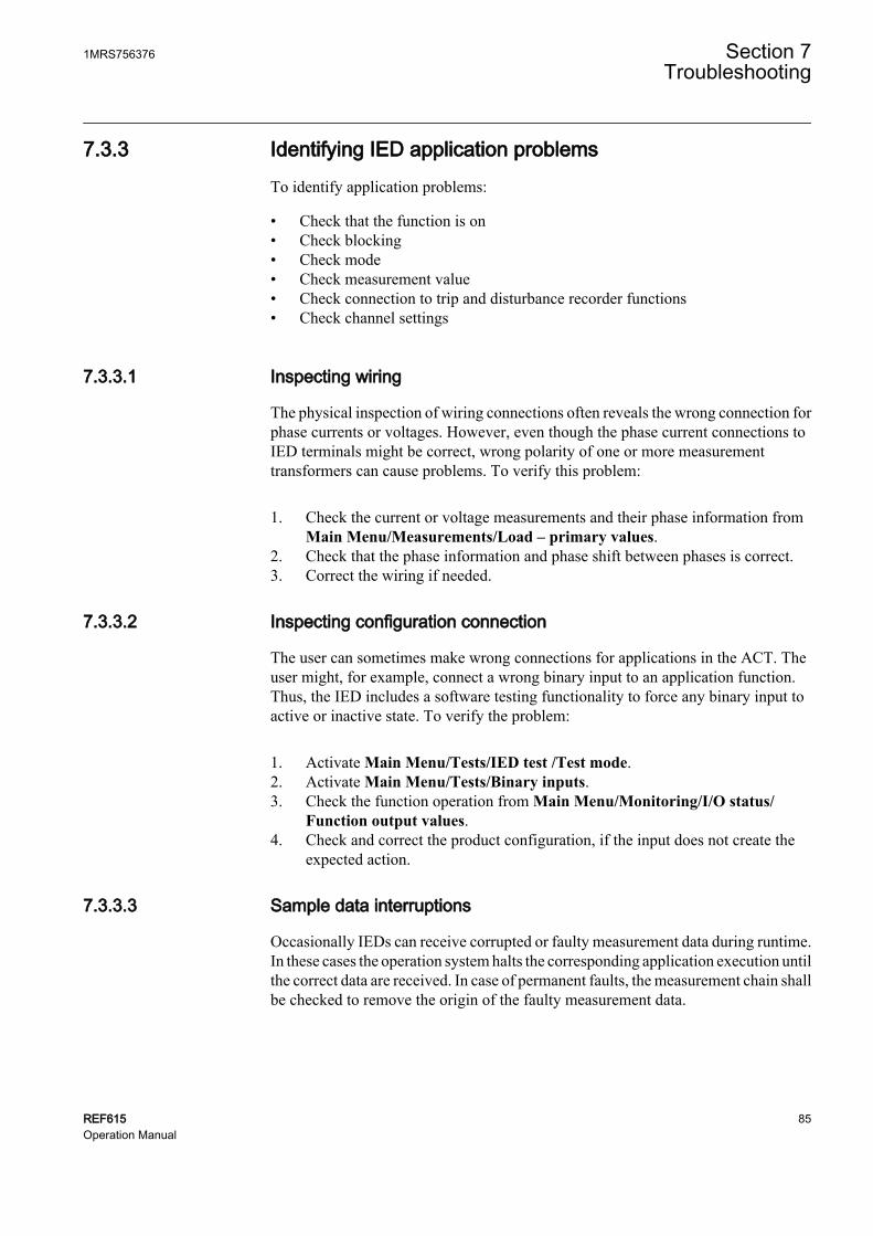
7.3.3 Identifying IED application problemsTo identify application problems:
• Check that the function is on• Check blocking• Check mode• Check measurement value• Check connection to trip and disturbance recorder functions• Check channel settings
7.3.3.1 Inspecting wiring
The physical inspection of wiring connections often reveals the wrong connection forphase currents or voltages. However, even though the phase current connections toIED terminals might be correct, wrong polarity of one or more measurementtransformers can cause problems. To verify this problem:
1. Check the current or voltage measurements and their phase information fromMain Menu/Measurements/Load – primary values.
2. Check that the phase information and phase shift between phases is correct.3. Correct the wiring if needed.
7.3.3.2 Inspecting configuration connection
The user can sometimes make wrong connections for applications in the ACT. Theuser might, for example, connect a wrong binary input to an application function.Thus, the IED includes a software testing functionality to force any binary input toactive or inactive state. To verify the problem:
1. Activate Main Menu/Tests/IED test /Test mode.2. Activate Main Menu/Tests/Binary inputs.3. Check the function operation from Main Menu/Monitoring/I/O status/
Function output values.4. Check and correct the product configuration, if the input does not create the
expected action.
7.3.3.3 Sample data interruptions
Occasionally IEDs can receive corrupted or faulty measurement data during runtime.In these cases the operation system halts the corresponding application execution untilthe correct data are received. In case of permanent faults, the measurement chain shallbe checked to remove the origin of the faulty measurement data.
1MRS756376 Section 7Troubleshooting
REF615 85Operation Manual

In case of persistent faults originating from IED's internal faults,contact ABB for repair or replacement actions.
Section 7 1MRS756376Troubleshooting
86 REF615Operation Manual

Section 8 Commissioning
8.1 Commissioning checklist
Familiarize yourself with the IED and its functionality before you start thecommissioning work.
• Ensure that you have all the needed station drawings such as single line andwiring diagrams.
• Ensure that your version of the technical reference manual applies to the IEDversion you test.
• Ensure that your setting software and connectivity packages work with the IEDversion you test.
• Find out if you need any additional software.• Ensure that you have the IED settings either on paper or in electronic format.
The settings and logic should be well documented.• Inspect the settings to ensure that they are correct.• Ensure that you have the correct cable to connect your PC to the IED's
communication port. The RJ-45 port supports any CAT 5 Ethernet cable but therecommendation is STP.
• Test your PC's communication port before you go to the site.• Find out who to contact if you have trouble and make sure you have a means to
contact them.• Find out who is responsible for the settings.• Ensure that you have with you the proper test equipment and all needed
connection cables.• Ensure that the owner of the switchgear familiarizes you with the work site and
any special aspects of it.• Ensure that you know how to operate in emergency situations. Find out where
the first aid and safety materials and exit routes are.
8.2 Checking installation
8.2.1 Checking the power supplyCheck that the auxiliary supply voltage remains within the permissible input voltagerange under all operating conditions. Check that the polarity is correct.
1MRS756376 Section 8Commissioning
REF615 87Operation Manual

8.2.2 Checking CT circuitsThe CTs must be connected in accordance with the terminal diagram provided withthe IED, both with regards to phases and polarity. The following tests arerecommended for every primary CT or CT core connected to the IED:
• Primary injection test to verify the current ratio of the CT, the correct wiring upto the protection IED and correct phase sequence connection (that is L1, L2,L3.)
• Polarity check to prove that the predicted direction of secondary current flow iscorrect for a given direction of primary current flow. This is an essential test forthe proper operation of the directional function, protection or measurement inthe IED.
• CT secondary loop resistance measurement to confirm that the currenttransformer secondary loop dc resistance is within specification and that thereare no high resistance joints in the CT winding or wiring.
• CT excitation test to ensure that the correct core in the CT is connected to theIED. Normally only a few points along the excitation curve are checked to ensurethat there are no wiring errors in the system, for example due to a mistake inconnecting the CT's measurement core to the IED.
• Check the earthing of the individual CT secondary circuits to verify that eachthree-phase set of main CTs is properly connected to the station earth and onlyat one electrical point.
• Insulation resistance check.
Both primary and secondary sides must be disconnected from the lineand IED when plotting the excitation characteristics.
If the CT secondary circuit is opened or its earth connection is missingor removed without the CT primary being de-energized first,dangerous voltages may be produced. This can be lethal and damage,for example, insulation. The re-energizing of the CT primary shouldbe inhibited as long as the CT secondary is open or unearthed.
8.2.3 Checking VT circuitsCheck that the wiring is in strict accordance with the supplied connection diagram.
Do not continue before any errors are corrected.
Test the circuitry. The following tests are recommended:
Section 8 1MRS756376Commissioning
88 REF615Operation Manual

• Polarity check• VT circuit voltage measurement (primary injection test)• Earthing check• Phase relationship• Insulation resistance check
The polarity check verifies the integrity of circuits and the phase relationships. Thepolarity should be measured as close as possible to the IED so ensure that most of thewiring is also checked.
The primary injection test verifies the VT ratio and the wiring all the way throughfrom the primary system to the IED. Injection must be performed for each phase-to-neutral circuit and each phase-to-phase pair. In each case voltages in all phases andneutral are measured.
8.2.4 Checking binary input and output circuits
8.2.4.1 Binary input circuits
Preferably, disconnect the binary input connector from the binary input cards. Checkall connected signals so that both input level and polarity are in accordance with theIEDs specifications.
8.2.4.2 Binary output circuits
Preferably, disconnect the binary output connector from the binary output cards.Check all connected signals so that both load and voltage are in accordance with theIED specifications.
8.3 Authorizations
8.3.1 User authorizationThe user categories have been predefined for LHMI and WHMI, each with differentrights and default passwords.
Passwords are settable. LHMI password must be at least four and WHMI passwordat least nine characters. Maximum number of characters is 20 for the WHMI passwordand 8 for the LHMI password. Only the following characters are accepted:
• Numbers 0-1• Letters a-z, A-Z• Space• Special characters !"#%&'()*+´-./:;<=>?@[\]^_`{|}~
1MRS756376 Section 8Commissioning
REF615 89Operation Manual
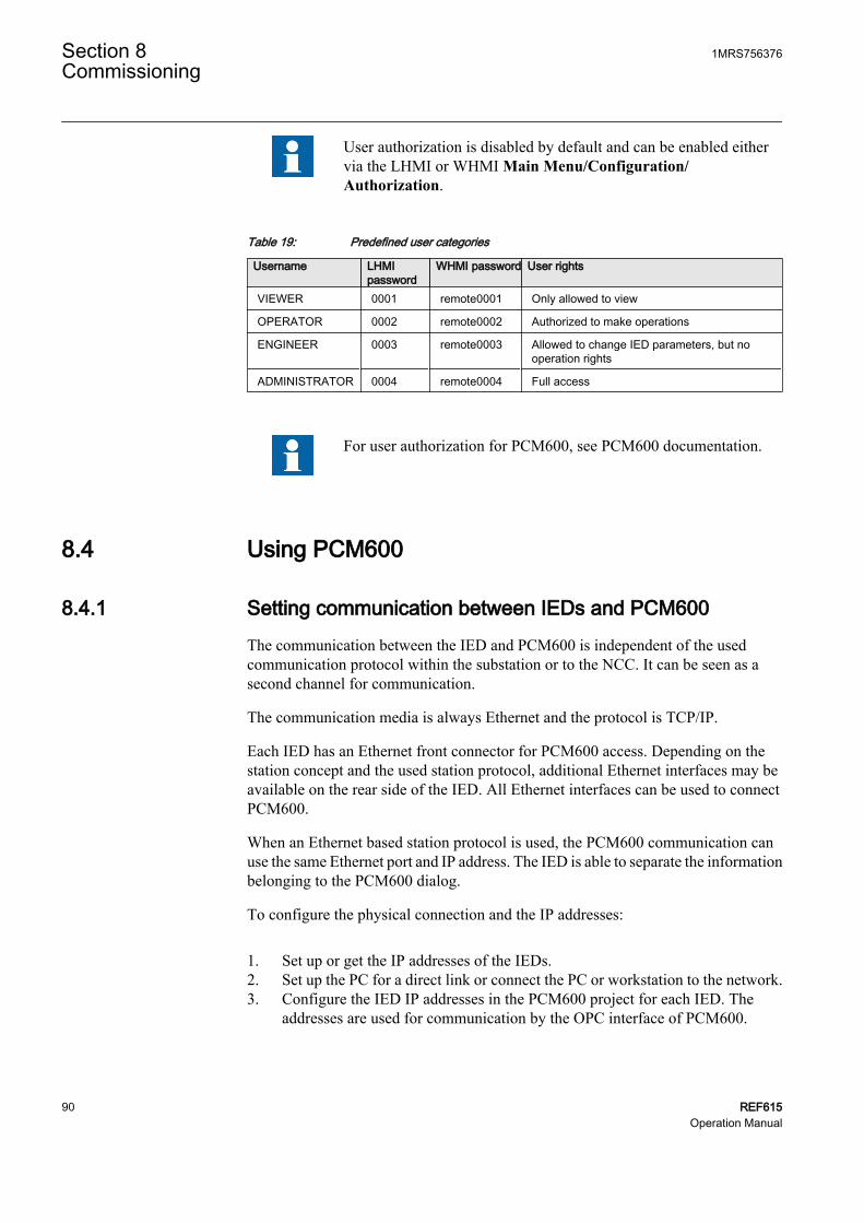
User authorization is disabled by default and can be enabled eithervia the LHMI or WHMI Main Menu/Configuration/Authorization.
Table 19: Predefined user categories
Username LHMIpassword
WHMI password User rights
VIEWER 0001 remote0001 Only allowed to view
OPERATOR 0002 remote0002 Authorized to make operations
ENGINEER 0003 remote0003 Allowed to change IED parameters, but nooperation rights
ADMINISTRATOR 0004 remote0004 Full access
For user authorization for PCM600, see PCM600 documentation.
8.4 Using PCM600
8.4.1 Setting communication between IEDs and PCM600The communication between the IED and PCM600 is independent of the usedcommunication protocol within the substation or to the NCC. It can be seen as asecond channel for communication.
The communication media is always Ethernet and the protocol is TCP/IP.
Each IED has an Ethernet front connector for PCM600 access. Depending on thestation concept and the used station protocol, additional Ethernet interfaces may beavailable on the rear side of the IED. All Ethernet interfaces can be used to connectPCM600.
When an Ethernet based station protocol is used, the PCM600 communication canuse the same Ethernet port and IP address. The IED is able to separate the informationbelonging to the PCM600 dialog.
To configure the physical connection and the IP addresses:
1. Set up or get the IP addresses of the IEDs.2. Set up the PC for a direct link or connect the PC or workstation to the network.3. Configure the IED IP addresses in the PCM600 project for each IED. The
addresses are used for communication by the OPC interface of PCM600.
Section 8 1MRS756376Commissioning
90 REF615Operation Manual

8.4.1.1 Communication options
Two options are available for the connection of PCM600 to the IED:
• Direct point to point link between PCM600 and the IED• Indirect link via a station LAN or from remote via a network
Point to point linkThe IED is provided with an RJ-45 connector on the front panel. The connector ismainly for configuration and setting purposes. Any Ethernet cable can be used butthe recommendation is STP.
The IED has a DHCP server for the front interface. The DHCP server assigns an IPaddress to the computer connected to the front interface. The computer's LANinterface has to be configured to obtain the IP address automatically.
LAN or WAN networkIn TCP/IP networking, a LAN is often but not always implemented as a single IPsubnet. A router connects LANs to a WAN. In IP networking, the router maintainsboth a LAN address and a WAN address. Design considerations for computernetworks cover a wide range of topics including layout, capacity planning, andsecurity. To some extent, the network configuration also depends on user preferences.
8.4.1.2 Setting communication parameters
The IP address and the corresponding mask can be set via the LHMI for the rear port.The front port uses a fixed IP address 192.168.0.254. The front port also usesDHCP.
Each Ethernet interface has a factory default IP address when the complete IED isdelivered.
Setting front communicationTo set up a standard PC with Microsoft Windows operating system for frontcommunication:
1. To open Network Connections, click Start, point to Settings, click ControlPanel, and then double-click Network Connections.
2. Double-click the connection that you want to configure, and then clickProperties.
3. Select the TCP/IP protocol from the list of configured components using thisconnection and click Properties.
1MRS756376 Section 8Commissioning
REF615 91Operation Manual

A071162 V1 EN
Figure 63: Selecting TCP/IP protocol
4. Select Obtain an IP address automatically and Obtain DNS server addressautomatically.
Section 8 1MRS756376Commissioning
92 REF615Operation Manual

A071224 V1 EN
Figure 64: Obtaining IP address automatically
5. Close all open windows by clicking OK and start PCM600.
Administrator rights are requested to change the configurationas described above.
Setting rear communicationTo set up a standard PC with MicroSoft Windows operating system for rearcommunication:
1. To open Network Connections, click Start, point to Settings, click ControlPanel, and then double-click Network Connections.
2. Double-click the connection that you want to configure, and then clickProperties.
3. Select the TCP/IP protocol from the list of configured components using thisconnection and click Properties.
1MRS756376 Section 8Commissioning
REF615 93Operation Manual

A071162 V1 EN
Figure 65: Selecting TCP/IP protocol
4. Choose Use the following IP address. Enter an IP address and a subnet mask.Make sure that the IP address is unique, that is not used by any other IED onthe network.
Section 8 1MRS756376Commissioning
94 REF615Operation Manual

A071164 V1 EN
Figure 66: Setting IP address and subnet mask
5. Close all open windows by clicking OK and start PCM600.
Administrator rights are requested to change the configurationas described above.
Setting IED's IP address in PCM600In PCM600 the IED's IP address can be defined either via the first window of thewizard by including a new IED in the project or by entering the IED's IP address inthe Object Properties window.
To define the IP address via the Object Properties window:
1. Select the IED to which you want to define the IP address.2. Open the Object Properties window.3. Place the cursor in the IP Address row and enter the IP address.
1MRS756376 Section 8Commissioning
REF615 95Operation Manual

The used method depends on the time at which the IP address is available. DefiningIP address in the Object Properties windows allows changing the IP address at anytime.
8.5 Setting IED and communication
8.5.1 Setting communicationThe IED is provided with an RJ-45 connector on the front panel. The connector ismainly used for configuration and setting purposes. The fixed IP address for the frontport is 192.168.0.254.
Different communication ports are available via optional communication modules.There are three options for rear port communication intended mainly for station levelcommunication, that is station bus. The options are galvanic Ethernet (RJ-45), opticalEthernet (LC) and RS-485/RS-232 twisted pair. Communication protocols used viaEthernet ports are IEC 61850-8-1 and Modbus TCP/IP. Protocol available forRS-485/RS-232 serial port is Modbus RTU/Modbus ASCII.
You can set the following communication parameters:
• To define the settings for the Ethernet port, select Main Menu/Configuration/Communication/Ethernet/Rear port.
• To define the settings for RS-485/RS-232 serial port, select Main Menu/Configuration/Communication/COM1 or Main Menu/Configuration/Communication/COM2.
• To define Modbus communication parameters, select Main Menu/Configuration/Communication/Modbus.
For more information, see Modbus Communication Protocol Manualand Technical Manual.
8.5.2 Setting LHMI
8.5.2.1 Changing LHMI language
To change the LHMI language:
1. Select Main Menu/Language and press .2. Change the language with or .3. Press to confirm the selection.4. Commit the changes.
Section 8 1MRS756376Commissioning
96 REF615Operation Manual

A071010 V2 EN
Figure 67: Changing the LHMI language
You can change the language also by pressing simultaneously and.
8.5.2.2 Adjusting display contrast
To obtain optimal readability, you can adjust the display contrast. The contrast canbe adjusted anywhere in the menu structure.
• To increase the contrast, press simultaneously and .• To decrease the contrast, press simultaneously and .
The selected contrast value is stored in the non-volatile memory if you are logged inand authorized to control the IED. After an auxiliary power failure, the contrast isrestored.
8.5.2.3 Changing display symbols
To switch between the display symbols IEC 61850, IEC 61617 and IEC-ANSI:
1. Select Main Menu/Configuration/HMI/FB naming convention and press.
2. Change the display symbols with or .3. Press to confirm the selection.
The IED has to be rebooted if the WHMI display symbols arechanged. With the LHMI, the change takes effect immediately.
8.5.2.4 Changing the default view
The default view of the display is the Measurements unless set otherwise.
To change the default view:
1MRS756376 Section 8Commissioning
REF615 97Operation Manual

1. Select Main Menu/Configuration/HMI/Default view and press .2. Change the default view with or .3. Press to confirm the selection.
8.5.2.5 Setting system time and time synchronization
To edit the date and time and the time synchronization source:
1. Select Main Menu/Configuration/Time/System time and press .2. Select the parameter with or .3. Press , change the value with or and press again.4. Repeat steps 2 and 3 to set the rest of the system time parameters.5. Select Main Menu/Configuration/Time/Synchronization/Synch source and
press .6. Set the time synchronization source to SNTP, Modbus or IRIG-B with or
.7. Press to confirm the selection.
If SNTP is used, the SNTP server's IP address is set in Main Menu/Configuration/Time/Synchronization/IP SNTP Primary and Main Menu/Configuration/Time/Synchronization/IP SNTP Secondary.
Setting daylight saving timeThe IED can be set to determine the correct date for the DST shift every year. TheUTC time is used to set the DST.
To define the DST shift:
1. Set the DST on day and DST off day parameters to define on which week daythe time shift occurs.
2. Set the DST on date and DST off date parameters to define on which month andweek the time shift occurs.The DST on/off date must precede the selected DST on/off day and be withinthe same week as the DST shift.
Table 20: DST change on Sunday
Day of the DST shift DST on/off dateFirst Sunday of the month 1
Second Sunday of the month 8
Third Sunday of the month 15
Fourth Sunday of the month 22
Last Sunday, if the month has 30 days 24
Last Sunday, if the month has 31 days 25
Section 8 1MRS756376Commissioning
98 REF615Operation Manual

For example, if the DST is observed from the last Sunday in March to the lastSunday in October and the time shift occurs at 01:00 UTC, the setting parametersare:
DST on time: 01:00
DST on date: 25.03
DST on day: Sun
DST off time: 01:00
DST off date: 25.10
DST off day: Sun
Set the DST on day and DST off day to "not in use" to determine theexact date and time for the DST shift. Repeat the setting yearly, as thetime for the DST shift is not on the same date every year.
To disable the DST, set the DST offset parameter to "0 min".
8.5.3 Setting IED parameters
8.5.3.1 Defining setting groups
Selecting a setting group for editingTo select a setting group:
1. Select Main Menu/Settings/Edit setting group.2. Select the setting group to be edited with or .3. Press to confirm the selection.4. Edit the settings.
A070858 V2 EN
Figure 68: Selecting a setting group
Browsing and editing setting group valuesTo browse setting group values:
1MRS756376 Section 8Commissioning
REF615 99Operation Manual

1. Select Main Menu/Settings/Settings and press .2. Select the setting group to be viewed with or and press to confirm
the selection.
A071166 V2 EN
Figure 69: Selecting setting group
3. To browse the settings, scroll the list with and and to select a settingpress .
4. To browse different function blocks, scroll the list with and and to selecta function block press . To move back to the list, press .The function block list is shown in the content area of the display. On the leftin the header, you see the current setting group, and on the right the menu path.
5. To browse the parameters, scroll the list with and and to select aparameter, press .The setting group values are indicated with #.
A070899 V2 EN
Figure 70: Setting group parameter
6. To select a setting group value, press and to edit the value press .
A071168 V2 EN
Figure 71: Selecting setting group value
Only values within the selected setting group can be changed.7. Press or to change the value and to confirm the selection.
Section 8 1MRS756376Commissioning
100 REF615Operation Manual

A070922 V2 EN
Figure 72: Editing setting group value
The active setting group is indicated with an asterisk * .
Activating a setting groupIED settings are planned in advance for different operation conditions by calculatingsetting values to different setting groups. The active setting group can be changed bythe IED application or manually from the menu.
To change the active setting group via the LHMI:
1. Select Main Menu/Settings/Setting group/Active group and press .
A071150 V2 EN
Figure 73: Active setting group
2. Select the setting group with or .3. Press to confirm the selection or to cancel.
A071152 V2 EN
Figure 74: Selecting active setting group
4. Commit the settings.
Remember to document the changes you make.
1MRS756376 Section 8Commissioning
REF615 101Operation Manual

8.5.3.2 IED parametrization
IED parameters are usually set with a parameter setting tool but it can also be donevia the LHMI or WHMI.
Setting parameters need to be calculated according to the electrical networkconditions and the electrical characteristics of the protected equipment. The IED'ssettings need to be verified before the IED is connected to a system.
For more information, see PCM600 documentation.
Document all changes to parameter settings.
8.5.3.3 Configuring analog inputs
To configure the CT and VT analog inputs:
1. Select Main Menu/Configuration/Analog inputs and press .2. Select the analog input to be configured with or .3. Press , change the value with or and press again.
• For CTs, the secondary current and primary current need to be set to thecorrect values.
• For VTs, the secondary voltage and primary voltage need to be set to thecorrect values.
8.6 Testing IED operation
The IED has to be in the test mode before the digital outputs and certain output signalsof protection and other functions can be activated.
8.6.1 Selecting test modeThe test mode can be activated using the LHMI. The green Ready LED will beblinking to indicate that the test mode is activated.
To activate or deactivate the test mode:
1. Select Main Menu/Tests/IED test/Test mode and press .
Section 8 1MRS756376Commissioning
102 REF615Operation Manual

A071154 V2 EN
Figure 75: Entering test mode
2. Select Test off or Test on with or .3. Press to confirm the selection.
If you do not cancel the test mode, it remains on and the Ready LEDremains blinking. Test mode does not retain if the IED is reset.
8.6.2 Testing digital I/O interfaceTo activate or deactivate, for example, a digital output:
1. Select Main Menu/Tests/Binary Outputs/X100 (PSM)/X100-Output 1 andpress .
2. Select False or True with or .3. Press to confirm the selection.
If the optional BIO-module (X110) is included in the IED, the menupath could also be Main Menu/Tests/Binary Outputs/X110(BIO1)/<binary output>.
8.6.3 Testing functionsTo activate or deactivate an output signal for protection or other function:
1. Select Main Menu/Tests/Function tests/Current protection/PHLPTOC andpress .
2. Select the output signal to be activated or deactivated with or and press.
3. To deactivate all output signals for the function, select Reset with or and press .
1MRS756376 Section 8Commissioning
REF615 103Operation Manual

8.6.4 Selecting internal fault testThe internal fault may be tested by using the LHMI. When enabling the test, theinternal relay fault output contact is activated, the green Ready LED will be blinkingand internal fault test indication is shown on the LHMI. See Technical Manual forinternal relay fault output contact location.
Differing from real internal fault situation, the other output contactsare not released and locked during the test. In other words, protectionfunctions can operate and trip the outputs when the internal fault istested.
To activate or deactivate internal fault test:
1. Select Main Menu/Tests/IED test/Internal fault test and press .
A071156 V2 EN
Figure 76: Internal fault test
2. Select False or True with or .3. Press to confirm the selection.
8.7 ABB Product Data Registration
The ABB Product Data Registration feature traces composition changes related tothe IED's SW or HW.
After a composition change, an LCT indication is seen on the LHMI at the IED start-up. At this point, PCM600 should be connected to the IED as it reads the changeddata from the IED. The LCT indication is cleared in the same way as other indications.If PCM600 is not connected to the IED, the indication is seen again after the IED'sreboot.
Section 8 1MRS756376Commissioning
104 REF615Operation Manual

A071266 V3 EN
Figure 77: LCT indication
The number of composition changes can be seen from the Composition changesparameter in Main Menu/Monitoring/IED status.
1MRS756376 Section 8Commissioning
REF615 105Operation Manual

106

Section 9 Glossary
100BASE-FX A physical media defined in the IEEE 802.3 Ethernetstandard for local area networks (LANs). 100BASE-FXuses fiber optic cabling.
100BASE-TX A physical media defined in the IEEE 802.3 Ethernetstandard for local area networks (LANs). 100BASE-TXuses twisted-pair cabling category 5 or higher with RJ-45connectors.
ACT Application Configuration Tool in PCM600ACT Trip statusAI Analog inputANSI American National Standards InstituteASCII American Standard Code for Information InterchangeBI Binary inputBI/O Binary input/outputCAT 5 A twisted pair cable type designed for high signal
integrityCB Circuit breakerCOMTRADE COMmon format for Transient Data Exchange for power
systems. Defined by the IEEE Standard.ConnectivityPackage Manager
Software that helps the user to define right connectivitypackage versions for different applications and tools.
CPU Central Processing UnitCSV Comma separated valuesCT Current transformerDHCP Dynamic Host Control Protocol allows devices joining
the network to dynamically receive an IP address fromthe DHCP server that contains a pool of IP addresses.
DMS Distribution Management SystemDST Daylight saving timeEEPROM Electrically Erasable Programmable Read-Only MemoryEthernet A large, diverse family of frame-based computer
networking technologies that operate at many speeds forLANs interconnecting computing devices. Ethernet is atrademark of Xerox Corporation, Inc. and defined in the
Section 9Glossary
REF615 107Operation Manual

IEEE 802.3 standard in which computers access thenetwork through a CSMA/CD protocol.
FB Function block.Firmware System software or hardware that has been written and
stored in a device's memory that controls the device.FPGA Field Programmable Gate ArrayGOOSE Generic Object Oriented Substation EventHMI Human-machine interfaceHW HardwareIEC International Electrotechnical CommissionIEC 61850 International standard for substation communication and
modelling.IEC 61850-8-1 A communication protocol based on the IEC 61850
standard series and a standard for substation modelling.IED Intelligent Electronic DeviceIP address Internet protocol address is a set of four numbers
between 0 and 255, separated by periods. Each serverconnected to the Internet is assigned a unique IPaddress that specifies a location for the TCP/IP protocol.
LAN Local area networkLC Connector type for glass fibre cable.LCD Liquid crystal displayLCP Liquid crystal polymerLCT Life cycle traceabilityLED Light-emitting diodeLHMI Local Human-Machine InterfaceModbus A serial communication protocol developed by the
Modicon company in 1979. Originally used forcommunication in PLCs and RTU devices.
Modbus ASCII Modbus link mode. Character length 10 bits.Modbus RTU Modbus link mode. Character length 11 bits.Modbus TCP/IP Modbus RTU protocol which uses TCP/IP and Ethernet
to carry data between devices.NCC Network control centerOPC OLE (object linking and embedding) for process controlPA PolyamidePBT Polybutylene terephthalate
Section 9Glossary
108 REF615Operation Manual

PC Personal Computer; PolycarbonatePCM600 Protection and Control IED ManagerPO Power outputR/L Remote/LocalRAM Random access memoryREF615 Feeder protection relayRJ-45 Galvanic connector type.RoHS Restriction of the use of certain Hazardous Substances
in electrical and electronic equipment.ROM Read Only MemoryRS-232 Serial interface standard.RS-485 Serial link according to EIA standard RS485.RTC Real Time ClockRTU Remote Terminal UnitSCADA Supervision, control and data acquisitionSCL Substation Configuration LanguageSMT Signal Matrix ToolSNTP Simple Network Time ProtocolSO Signal outputSTP Shielded Twisted-PairSVG Scalable Vector GraphicsSW SoftwareTCP/IP Transmission Control Protocol / Internet ProtocolTCS Trip-circuit supervisionUTC Universal Time CoordinatedUTF-8 8-bit Unicode Transformation Format that serializes a
Unicode scalar value as a sequence of one to four bytes.VT Voltage transformerWAN Wide area networkWHMI Web Human-Machine Interface
Section 9Glossary
REF615 109Operation Manual

110

111

1MR
S756
376
ABB OyDistribution AutomationP.O. Box 699FI-65101 VAASA, FinlandPhone +358 10 22 11Fax +358 10 22 41094www.abb.com/substationautomation Copyright 2008 - ABB


![Quantifiers, Unit Symbols, Chemical Symbols and Symbols of … · 2019-02-26 · [Technical Data] Quantifiers, Unit Symbols, Chemical Symbols and Symbols of Elements Excerpts from](https://static.fdocuments.in/doc/165x107/5ea0ef282df5855ac23d36fb/quantifiers-unit-symbols-chemical-symbols-and-symbols-of-2019-02-26-technical.jpg)

