Federico Rossi - CIRIAF
11
Transcript of Federico Rossi - CIRIAF


Federico Rossie-mail: [email protected]
Andrea Nicolini1e-mail: [email protected]
University of Perugia,
Department of Industrial Engineering,
via G. Duranti n. 67, 06125 Perugia, Italy
Experimental Investigation on aNovel Electrolyte Configurationfor Cylindrical Molten CarbonateFuel CellsAn experimental investigation on a novel electrolyte configuration for molten carbonatefuel cells (MCFCs) is presented. A single cell facility was built. The cell is characterizedby a cylindrical geometry in order to reduce the structural and thermodynamic problemswhich affect the lifetime of the traditional rectangular shape MCFCs. The main aim of thisresearch is to evaluate the possibility of not installing the porous ceramic matrix in orderto reduce the gas crossover problems of MCFCs and improve the cell lifetime. Thus, thenew single cell was mainly constituted by the porous electrodes, the liquid electrolyte andstructural disks as electrolytic support. Different solutions were studied as mechanicalsupport for the electrolyte. Experimental tests on the proposed solutions were performed.Results suggested that the proposed adjustments are a promising solution for increasingthe lifetime of cylindrical MCFCs and reducing their costs. [DOI: 10.1115/1.4003773]
Keywords: control, degradation, experimental results, geometry variations, MCFC
1 Introduction
Molten carbonate fuel cells (MCFCs) are characterized by thefollowing cost-effective theoretical properties that could lead to afuture commercialization as stationary energy production plants[1,2]:
• high efficiency (theoretically up to 60%);• low environmental impact;• low fabrication costs of the industrialized product;• cogeneration due to the high temperature working conditions;• high tolerability to the fuel impurities;• possibility to be directly supplied by natural gas from grid
thank to internal or external reformer stages.
However, MCFCs are characterized by technical limits whichslow their commercialization, especially for the residential mar-ket: long start-up times, a lifetime limited by gas crossover phe-nomena and stability of the materials (they may be affected bycorrosion and oxidation phenomena). Currently, a mature technol-ogy is only limited to large size MCFCs (over 100 kW).
Traditional shape MCFCs are characterized by a square or rec-tangular geometry [1,2]. Novel cylindrical cell geometries forsmall size MCFCs were patented and proposed in previous works[3–6]. The cylindrical geometry of the cell components (electro-des, matrix) helps to reduce the traditional problems of square andrectangular geometry MCFCs. In fact, traditional MCFC elementsare produced by the tape casting technique [7]; cylindrical cellelements may be easily obtained by injection moulding, a tech-nique which may be conveniently used for large scale productionsof small size cells, with high benefits in terms of fabrication timesand costs. Furthermore, traditional MCFCs are characterized byhigh thermal outward dispersions. A cylindrical geometry helps tominimize the thermal dispersions both for its geometry intrinsicproperties and the easiness to thermally insulate such device. This
property contributes to improve the cell global efficiency. Cylin-drical MCFCs are also characterized by:
• reduced gas sealing problems due to the lack of edges;• external manifolds which allow different stack size;• a reduced compression strain disuniformity on each plate
contact surface due to the symmetry of the cell elements.
A cylindrical small size MCFC is the result of multi-annual activ-ities performed at the Fuel Cell Laboratory of University of Perugiaheadquartered in Terni (Italy); it is patented by IPASS [3–6]. Theoptimum size for the mentioned cylindrical MCFCs is in the [1 kW,5 kW] range: in this way, the mentioned benefits, thermal self-sus-tain conditions, cogeneration and a compact design may beobtained. A previous work showed the proposed technology suitablefor lCHP applications; a $2000/kW target price was determined byan economical evaluation [8].
This paper reports the results of an experimental investigation onnovel solutions for improving the performances of the mentionedcylindrical MCFCs by reducing the gas crossover phenomena dueto the porosity variability of ceramic matrices. The proposal is toavoid the installation of the porous matrix as electrolyte support.Different structural solutions were tested by a specific single cellcylindrical facility. The single cell facility was mainly constitutedby porous electrodes (anode and cathode), the liquid electrolyte andstructural disks as electrolytic support. Experimental tests were con-ducted to determine the optimum configuration and to evaluate thesuitability of the proposed solutions. Voltage-current density andpower-current density characteristic curves were compared for eachtested configuration in order to determine the best solution as elec-trolytic support. Results showed that the proposed MCFC configu-ration may be a viable solution to increase MCFC lifetime and tosolve the gas crossover problems which have put back their com-mercialization for residential lCHP applications.
2 Gas Crossover on MCFCs: The Proposed Solutions
MCFC lifetime is particularly affected by gas crossover phenom-ena, which typically consists in anodic gas drift toward the cathodiccompartment: in particular, two kinds of gas crossover phenomenamay occur for MCFC traditional configurations: structural gas cross-over and diffuse gas crossover through the porous matrix.
1Corresponding author.Contributed by the Advanced Energy Systems Division of ASME for publication
in the JOURNAL OF FUEL CELL SCIENCE AND TECHNOLOGY. Manuscript received Septem-ber 10, 2010; Final manuscript received January 26, 2011; Published online June 20,2011. Assoc. Editor: Stefano Ubertini.
Journal of Fuel Cell Science and Technology OCTOBER 2011, Vol. 8 / 051012-1Copyright VC 2011 by ASME
Downloaded 20 Jun 2011 to 184.152.32.239. Redistribution subject to ASME license or copyright; see http://www.asme.org/terms/Terms_Use.cfm
Structural gas crossover is given by the cell configuration dis-continuities. For example, anodic gases may go directly to the ca-thodic compartment through the cell edges or a gas manifoldedge. A cylindrical MCFC configuration with vertical gas mani-folds gives a great reduction of this kind of gas crossover phenom-ena: thermal dilatations are compensated from the cylindricalstructure and its pressure seal mechanical system [4–6]. On thecontrary, structural gas crossover phenomena often occur for therectangular section traditional MCFCs with lateral gas manifolds[9].
Diffuse gas crossover through the porous matrix is given by thetraditional c-LiAlO2 MCFC matrix characteristics. The matrix isinstalled between the electrodes (anode and cathode); in this way,it holds the Li/K molten carbonates between the two electrodes,avoiding their leakage through the other cell components. Further-more, the matrix keeps the two electrodes separated: in this way,the electrode collapse is avoided and the anodic and cathodiccompartments are electrically insulated. Thus, the matrix has to becharacterized by specific chemical-physical characteristics inorder to give the mentioned properties to the cell. However, someproblems occur which affect the MCFC performances due to thedifficulty to obtain optima matrix characteristics.
Firstly, c-LiAlO2 is not a common material; thus, its cost isvery high and this fact increases the global cell cost. c-LiAlO2 ce-ramic matrices are installed into the cell in a “green” state (joinedby an organic binder). The organic binder successively melts andevaporates during the cell conditioning step, which is a verylong process (approximately 1 week): hence, conditioning andstart-up processes are very sensitive phases because they mayaffect the matrix configuration and the stack working conditions.Furthermore, the matrix production is usually obtained by ahumid molding technique, which is a very hard and long process.Thermal resistance and porosity specifications for the producedmatrices are very strictly; thus, the production process maydemand a drastic selection for the finished products and the costsmay further increase. The produced matrices are also character-ized by a very low resistance to the mechanical stresses: thus,problems may occur for their transport and the cell assemblingprocess.
Hence, the need of installing a porous matrix makes the MCFCassembling process very hard: the role of the porous matrix is im-portant for having correct MCFC working conditions, but it intro-duces many problems. As mentioned before, the matrix porosityis a fundamental parameter to have correct working conditions.Li/K molten carbonates distribution has to give a stable three-phase (gas-electrolyte-solid) interface. It may be obtained inMCFCs exclusively by a balance in capillary pressures. The diam-eters of the largest flooded pores are related by the followingequation (1)
ca cos ha
Da¼ cc cos hc
Dc¼ cm cos hm
Dm(1)
where c is the interfacial surface tension, h the contact angle ofthe electrolyte, D the pore diameter and subscripts a, c, and mrefer to the anode, cathode and electrolyte matrix, respectively.Typically, the porosity characteristics of these elements have tobe the followings [1,10]:
• anode: 3–6 lm average pore diameter, 45–70% porosity;• cathode, 7–15 lm average pore diameter, 70–80% porosity;• matrix, average pore diameter< 1 lm, 30–70% porosity.
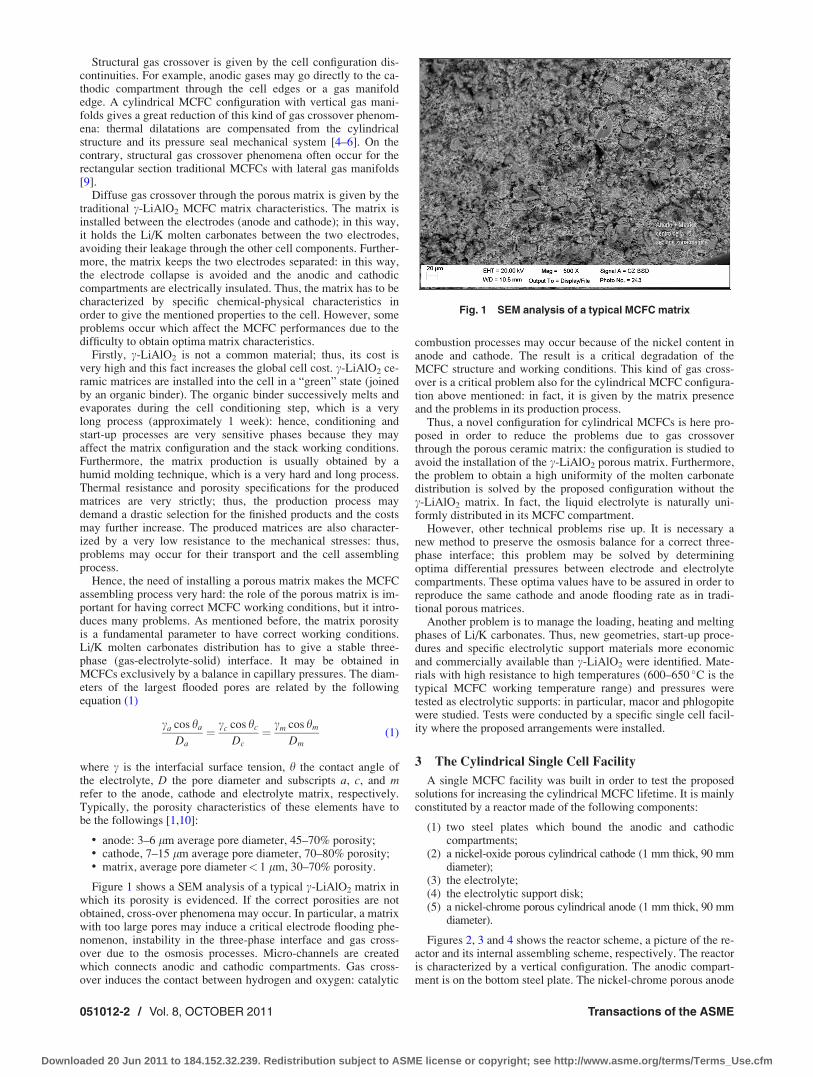
Figure 1 shows a SEM analysis of a typical c-LiAlO2 matrix inwhich its porosity is evidenced. If the correct porosities are notobtained, cross-over phenomena may occur. In particular, a matrixwith too large pores may induce a critical electrode flooding phe-nomenon, instability in the three-phase interface and gas cross-over due to the osmosis processes. Micro-channels are createdwhich connects anodic and cathodic compartments. Gas cross-over induces the contact between hydrogen and oxygen: catalytic
combustion processes may occur because of the nickel content inanode and cathode. The result is a critical degradation of theMCFC structure and working conditions. This kind of gas cross-over is a critical problem also for the cylindrical MCFC configura-tion above mentioned: in fact, it is given by the matrix presenceand the problems in its production process.
Thus, a novel configuration for cylindrical MCFCs is here pro-posed in order to reduce the problems due to gas crossoverthrough the porous ceramic matrix: the configuration is studied toavoid the installation of the c-LiAlO2 porous matrix. Furthermore,the problem to obtain a high uniformity of the molten carbonatedistribution is solved by the proposed configuration without thec-LiAlO2 matrix. In fact, the liquid electrolyte is naturally uni-formly distributed in its MCFC compartment.
However, other technical problems rise up. It is necessary anew method to preserve the osmosis balance for a correct three-phase interface; this problem may be solved by determiningoptima differential pressures between electrode and electrolytecompartments. These optima values have to be assured in order toreproduce the same cathode and anode flooding rate as in tradi-tional porous matrices.
Another problem is to manage the loading, heating and meltingphases of Li/K carbonates. Thus, new geometries, start-up proce-dures and specific electrolytic support materials more economicand commercially available than c-LiAlO2 were identified. Mate-rials with high resistance to high temperatures (600–650 �C is thetypical MCFC working temperature range) and pressures weretested as electrolytic supports: in particular, macor and phlogopitewere studied. Tests were conducted by a specific single cell facil-ity where the proposed arrangements were installed.
3 The Cylindrical Single Cell Facility
A single MCFC facility was built in order to test the proposedsolutions for increasing the cylindrical MCFC lifetime. It is mainlyconstituted by a reactor made of the following components:
(1) two steel plates which bound the anodic and cathodiccompartments;
(2) a nickel-oxide porous cylindrical cathode (1 mm thick, 90 mmdiameter);
(3) the electrolyte;(4) the electrolytic support disk;(5) a nickel-chrome porous cylindrical anode (1 mm thick, 90 mm
diameter).
Figures 2, 3 and 4 shows the reactor scheme, a picture of the re-actor and its internal assembling scheme, respectively. The reactoris characterized by a vertical configuration. The anodic compart-ment is on the bottom steel plate. The nickel-chrome porous anode
Fig. 1 SEM analysis of a typical MCFC matrix
051012-2 / Vol. 8, OCTOBER 2011 Transactions of the ASME
Downloaded 20 Jun 2011 to 184.152.32.239. Redistribution subject to ASME license or copyright; see http://www.asme.org/terms/Terms_Use.cfm
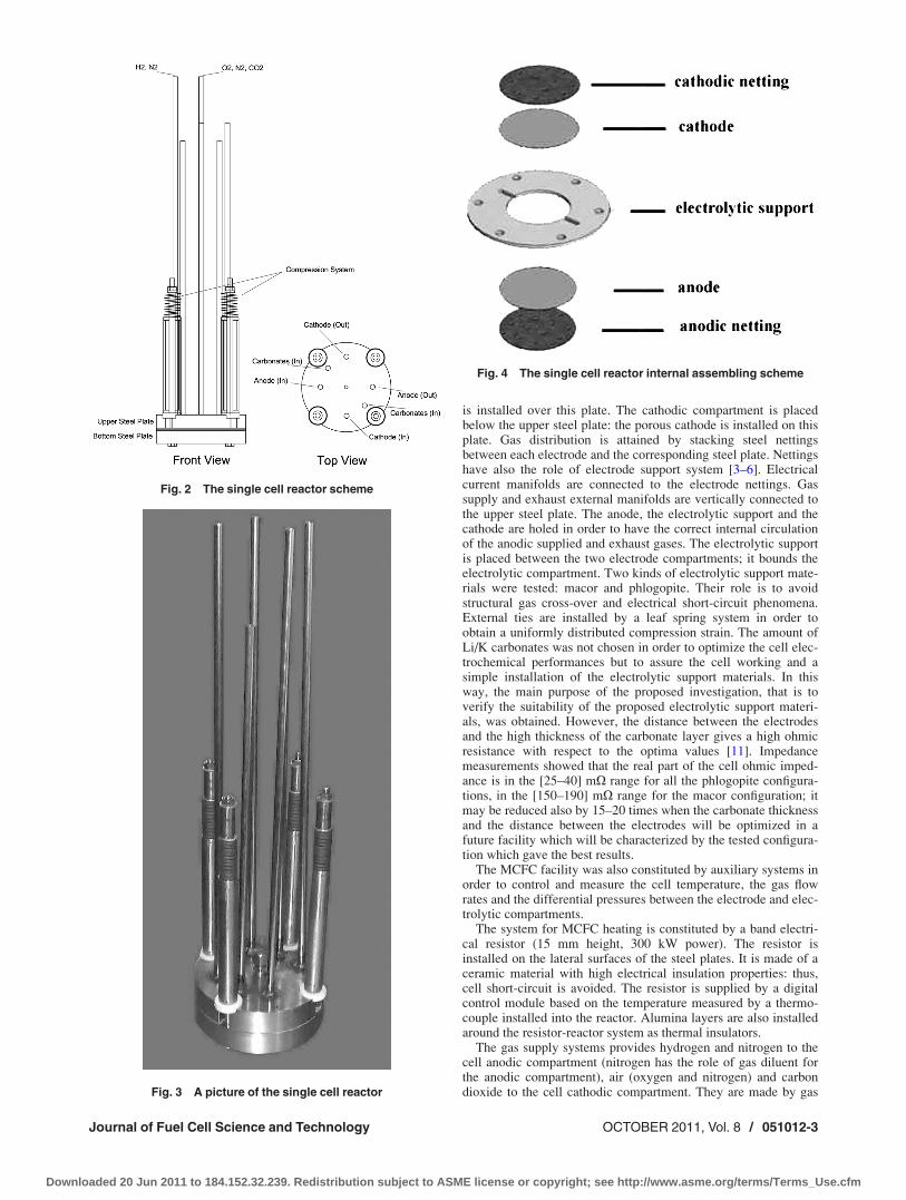
is installed over this plate. The cathodic compartment is placedbelow the upper steel plate: the porous cathode is installed on thisplate. Gas distribution is attained by stacking steel nettingsbetween each electrode and the corresponding steel plate. Nettingshave also the role of electrode support system [3–6]. Electricalcurrent manifolds are connected to the electrode nettings. Gassupply and exhaust external manifolds are vertically connected tothe upper steel plate. The anode, the electrolytic support and thecathode are holed in order to have the correct internal circulationof the anodic supplied and exhaust gases. The electrolytic supportis placed between the two electrode compartments; it bounds theelectrolytic compartment. Two kinds of electrolytic support mate-rials were tested: macor and phlogopite. Their role is to avoidstructural gas cross-over and electrical short-circuit phenomena.External ties are installed by a leaf spring system in order toobtain a uniformly distributed compression strain. The amount ofLi/K carbonates was not chosen in order to optimize the cell elec-trochemical performances but to assure the cell working and asimple installation of the electrolytic support materials. In thisway, the main purpose of the proposed investigation, that is toverify the suitability of the proposed electrolytic support materi-als, was obtained. However, the distance between the electrodesand the high thickness of the carbonate layer gives a high ohmicresistance with respect to the optima values [11]. Impedancemeasurements showed that the real part of the cell ohmic imped-ance is in the [25–40] mX range for all the phlogopite configura-tions, in the [150–190] mX range for the macor configuration; itmay be reduced also by 15–20 times when the carbonate thicknessand the distance between the electrodes will be optimized in afuture facility which will be characterized by the tested configura-tion which gave the best results.
The MCFC facility was also constituted by auxiliary systems inorder to control and measure the cell temperature, the gas flowrates and the differential pressures between the electrode and elec-trolytic compartments.
The system for MCFC heating is constituted by a band electri-cal resistor (15 mm height, 300 kW power). The resistor isinstalled on the lateral surfaces of the steel plates. It is made of aceramic material with high electrical insulation properties: thus,cell short-circuit is avoided. The resistor is supplied by a digitalcontrol module based on the temperature measured by a thermo-couple installed into the reactor. Alumina layers are also installedaround the resistor-reactor system as thermal insulators.
The gas supply systems provides hydrogen and nitrogen to thecell anodic compartment (nitrogen has the role of gas diluent forthe anodic compartment), air (oxygen and nitrogen) and carbondioxide to the cell cathodic compartment. They are made by gas
Fig. 2 The single cell reactor scheme
Fig. 3 A picture of the single cell reactor
Fig. 4 The single cell reactor internal assembling scheme
Journal of Fuel Cell Science and Technology OCTOBER 2011, Vol. 8 / 051012-3
Downloaded 20 Jun 2011 to 184.152.32.239. Redistribution subject to ASME license or copyright; see http://www.asme.org/terms/Terms_Use.cfm
bottles, mass-flow systems, manometers, electrovalves, and pres-sure reducers. Gas flow rates are controlled and monitored by dataacquisition and digital control modules.
The proposed MCFC configuration may be characterized bycarbonate dispersion problems which can affect the correct three-phase interface and the cell working conditions. Therefore, thecorrect electrode flooding rate obtained by the matrix porosity hasto be kept also by the proposed configuration. A control systemconstituted by pipes, needle valves, ball valves, manometers anddata acquisition/control modules was installed to control the dif-ferential pressures between each electrode compartment and theelectrolytic one. Two manometers are used to measure the electro-lytic compartment pressure. Two manometers are also used tomeasure the anodic and cathodic compartment pressures. Needlevalves are connected to the exhaust ducts of each electrode com-partment in order to control the pressure conditions. Ball valvesare used to control the electrolytic compartment pressure rela-tively to the electrode compartment ones. Thus, the pressure con-trol system may give a cell which works with the same electrodeflooding rate of the cell with the porous matrix.
A variable electrical load was connected to the cell for evaluat-ing its electrical performances and comparing the proposed con-figuration solutions. The single cell voltage and current weremeasured by Hall effect probes, inconel wires and electricalmultimeters.
A picture of the entire single cell facility is shown in Fig. 5.
4 Experimental Tests
Experimental tests were conducted by the single cell facilityto evaluate the suitability of the proposed solutions. Two electro-lytic supports were tested: macor and phlogopite. They are mate-rials with high electrical insulation properties (volume resistivityhigher than 1013 X-cm) and resistance to high working tempera-tures (their stability is assured up to 900–1000 �C). Furthermore,no corrosion or deterioration phenomena may occur when theyare in contact with the electrolyte also for long term exposures: itwas verified by the cylindrical MCFC equipped with the c-LiAlO2 matrix where they are usually used as electrical insula-tion materials and they are in contact with the same electrolyte[3–6]: no corrosion or deterioration phenomena occurred bothfor macor and phlogopite, also for 10.000 h exposures to theelectrolytic contact.
The performances of the proposed cylindrical MCFC configura-tion were evaluated by varying the following parameters:
• working temperature;• gas flow rates;• pressures in the anodic, cathodic and electrolytic compartments;• kind of electrolytic support;
• reaction active area of the electrodes.
Three kinds of experimental tests were performed: the first onewas conducted by using macor as electrolytic support, the secondand the third ones were conducted by using two configurations ofphlogopite electrolytic support.
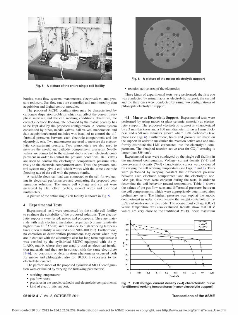
4.1 Macor as Electrolytic Support. Experimental tests wereperformed by using macor (a glass-ceramic material) as electro-lytic support. The proposed electrolytic support is characterizedby a 3 mm thickness and a 100 mm diameter. It has a 1 mm thick-ness and a 50 mm diameter groove where Li/K carbonates takeplace (see Fig. 6). Furthermore, holes and grooves are made onthe support in order to maximize the reaction active area and uni-formly distribute the Li/K carbonates into the electrolytic com-partment. The obtained reaction active area for CO3
¼ crossing islarger than 3.04 cm2.
Experimental tests were conducted by the single cell facility inthe mentioned configuration. Voltage- current density (V-J) andpower-current density (W-J) characteristic curves were evaluatedby varying the cell working temperature (see Figs. 7 and 8). Testswere performed by keeping constant the differential pressurebetween each electrode compartment and the electrolytic one.Also gas flow rates were constant during the tests, in order todetermine the cell behavior toward temperature. Table 1 showsthe values of the gas flow rates and differential pressures betweenthe cell compartments, which were appropriately determined afterpreliminary tests. The highest pressure was kept at the anodiccompartment in order to compensate the weight contribute of theLi/K carbonates on the electrode. The open-circuit voltage (OCV)versus temperature was also evaluated. Results show that OCVvalues are very close to the traditional MCFC ones: maximum
Fig. 5 A picture of the entire single cell facility
Fig. 6 A picture of the macor electrolytic support
Fig. 7 Cell voltage- current density (V-J) characteristic curvefor different working temperatures (macor electrolytic support)
051012-4 / Vol. 8, OCTOBER 2011 Transactions of the ASME
Downloaded 20 Jun 2011 to 184.152.32.239. Redistribution subject to ASME license or copyright; see http://www.asme.org/terms/Terms_Use.cfm
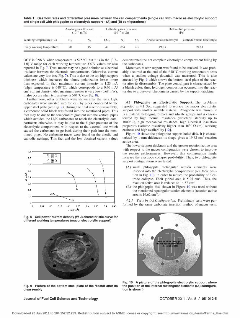
OCV is 0.98 V when temperature is 575 �C, but it is in the [0.7–1.0] V range for each working temperature. OCV values are alsoreported in Fig. 7. Thus, macor may be a good solution as electricalinsulator between the electrode compartments. Otherwise, currentvalues are very low (see Fig. 7). This is due to the too high supportthickness which increases the ohmic polarization losses morethan expected. In fact, maximum current intensity is 1.23 mA(when temperature is 640 �C), which corresponds to a 0.40 mA/cm2 current density. Also maximum power is very low (0.68 mW);it also occurs when temperature is 640 �C (see Fig. 8).
Furthermore, other problems were shown after the tests. Li/Kcarbonates were inserted into the cell by pipes connected to theupper steel plate (see Fig. 2). During the final reactor disassembly,a carbonate solid block was found into the mentioned pipes. Thisfact may be due to the temperature gradient into the vertical pipeswhich avoided the Li/K carbonates to reach the electrolytic com-partment; otherwise, it may be due to the higher pressure of theelectrolytic compartment with respect to the external one whichcaused the carbonates to go back during their path into the men-tioned pipes. No carbonate traces were found on the anodic andcathodic nettings. This fact and the low obtained current values
demonstrated the not complete electrolytic compartment filling bythe carbonates.
Moreover, macor support was found to be cracked. It was prob-ably occurred at the end of the 640 �C working temperature testswhen a sudden voltage downfall was measured. This is alsoattested by Fig. 9 which shows the bottom steel plate of the reac-tor after its disassembly. The plate central part is characterized bya bluish color; thus, hydrogen combustion occurred into the reac-tor due to cross-over phenomena caused by the support cracking.
4.2 Phlogopite as Electrolytic Support. The problemsreported in 4.1 Sec. suggested to replace the macor electrolyticsupport with another suitable material. Phlogopite was chosen: itis a material belonging to mica and silicate groups and is charac-terized by high thermal resistance (structural stability up to1000 �C), high mechanical resistance, high electrical insulationproperties (volume resistivity higher than 1013 X-cm), workingeasiness and high availability [12].
Figure 10 shows the phlogopite support holed disk. It is charac-terized by 1 mm thickness; its shape gives a 19.62 cm2 reactionactive area.
The lower support thickness and the greater reaction active areawith respect to the macor configuration were chosen to improvethe reactor performances. However, this configuration mightincrease the electrode collapse probability. Thus, two phlogopitesupport configurations were tested:
(A) small phlogopite rectangular section elements wereinserted into the electrolytic compartment (see their posi-tion in Fig. 10), in order to reduce the probability of elec-trode collapse. Their global area is 5.25 cm2. Thus, thereaction active area is reduced to 14.37 cm2.
(B) the phlogopite disk shown in Figure 10 was used withoutthe mentioned rectangular section elements (reaction activearea is 19.62 cm2).
4.2.1 Tests by (A) Configuration. Preliminary tests were per-formed by the same carbonate insertion method of macor tests.
Fig. 8 Cell power-current density (W-J) characteristic curve fordifferent working temperatures (macor electrolytic support)
Table 1 Gas flow rates and differential pressures between the cell compartments (single cell with macor as electrolytic supportand single cell with phlogopite as electrolytic support – (A) and (B) configurations)
Anodic gases flow rate(10�3 m3/h)
Cathodic gases flow rate(10�3 m3/h)
Differential pressure(Pa)
Working temperature (�C) H2 N2 CO2 N2 O2 Anode versus Electrolyte Cathode versus Electrolyte
Every working temperature 50 45 40 234 63 490.3 247.1
Fig. 9 Picture of the bottom steel plate of the reactor after itsdisassembly
Fig. 10 A picture of the phlogopite electrolytic support wherethe position of the internal rectangular elements ((A) configura-tion is shown)
Journal of Fuel Cell Science and Technology OCTOBER 2011, Vol. 8 / 051012-5
Downloaded 20 Jun 2011 to 184.152.32.239. Redistribution subject to ASME license or copyright; see http://www.asme.org/terms/Terms_Use.cfm
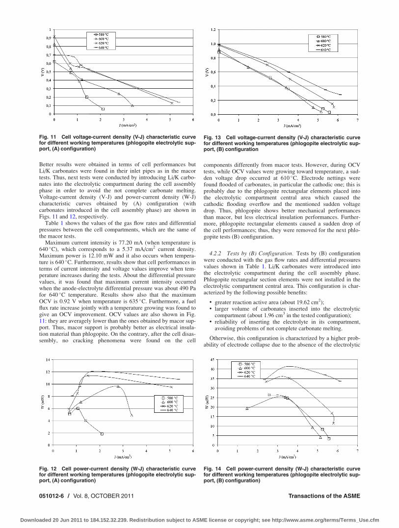
Better results were obtained in terms of cell performances butLi/K carbonates were found in their inlet pipes as in the macortests. Thus, next tests were conducted by introducing Li/K carbo-nates into the electrolytic compartment during the cell assemblyphase in order to avoid the not complete carbonate melting.Voltage-current density (V-J) and power-current density (W-J)characteristic curves obtained by (A) configuration (withcarbonates introduced in the cell assembly phase) are shown inFigs. 11 and 12, respectively.
Table 1 shows the values of the gas flow rates and differentialpressures between the cell compartments, which are the same ofthe macor tests.
Maximum current intensity is 77.20 mA (when temperature is640 �C), which corresponds to a 5.37 mA/cm2 current density.Maximum power is 12.10 mW and it also occurs when tempera-ture is 640 �C. Furthermore, results show that cell performances interms of current intensity and voltage values improve when tem-perature increases during the tests. About the differential pressurevalues, it was found that maximum current intensity occurredwhen the anode-electrolyte differential pressure was about 490 Pafor 640 �C temperature. Results show also that the maximumOCV is 0.92 V when temperature is 635 �C. Furthermore, a fuelflux rate increase jointly with a temperature growing was found togive an OCV improvement. OCV values are also shown in Fig.11: they are averagely lower than the ones obtained by macor sup-port. Thus, macor support is probably better as electrical insula-tion material than phlogopite. On the contrary, after the cell disas-sembly, no cracking phenomena were found on the cell
components differently from macor tests. However, during OCVtests, while OCV values were growing toward temperature, a sud-den voltage drop occurred at 610 �C. Electrode nettings werefound flooded of carbonates, in particular the cathodic one; this isprobably due to the phlogopite rectangular elements placed intothe electrolytic compartment central area which caused thecathodic flooding overflow and the mentioned sudden voltagedrop. Thus, phlogopite shows better mechanical performancesthan macor, but less electrical insulation performances. Further-more, phlogopite rectangular elements caused a sudden drop ofthe cell performances; thus, they were removed for the next phlo-gopite tests (B) configuration.
4.2.2 Tests by (B) Configuration. Tests by (B) configurationwere conducted with the gas flow rates and differential pressuresvalues shown in Table 1. Li/K carbonates were introduced intothe electrolytic compartment during the cell assembly phase.Phlogopite rectangular section elements were not installed in theelectrolytic compartment central area. This configuration is char-acterized by the following possible benefits:
• greater reaction active area (about 19.62 cm2);• larger volume of carbonates inserted into the electrolytic
compartment (about 1.96 cm3 in the tested configuration);• reliability of inserting the electrolyte in its compartment,
avoiding problems of not complete carbonate melting.
Otherwise, this configuration is characterized by a higher prob-ability of electrode collapse due to the absence of the electrolytic
Fig. 11 Cell voltage-current density (V-J) characteristic curvefor different working temperatures (phlogopite electrolytic sup-port, (A) configuration)
Fig. 12 Cell power-current density (W-J) characteristic curvefor different working temperatures (phlogopite electrolytic sup-port, (A) configuration)
Fig. 13 Cell voltage-current density (V-J) characteristic curvefor different working temperatures (phlogopite electrolytic sup-port, (B) configuration
Fig. 14 Cell power-current density (W-J) characteristic curvefor different working temperatures (phlogopite electrolytic sup-port, (B) configuration)
051012-6 / Vol. 8, OCTOBER 2011 Transactions of the ASME
Downloaded 20 Jun 2011 to 184.152.32.239. Redistribution subject to ASME license or copyright; see http://www.asme.org/terms/Terms_Use.cfm
support in the central area of the electrolytic compartment; a highelectrode flooding rate may also occur.
Voltage-current density (V-J) and power-current density (W-J)characteristic curves obtained by B) configuration are respectivelyshown in Figs. 13 and 14 (working parameters in Table 1). AlsoOCV values are shown in Fig. 13. It is shown that a temperaturegrowing induces an improvement of the cell performances. Maxi-mum current value is 120.05 mA at 640 �C which corresponds toa 6.12 mA/cm2 current density. Maximum power is 41.45 mW at640 �C. Furthermore, OCV values are very close to the traditionalMCFC ones for each temperature condition. The maximum value(1.01 V) was obtained at 630 �C. Thus, results show the good gassealing of electrode and electrolytic compartments.
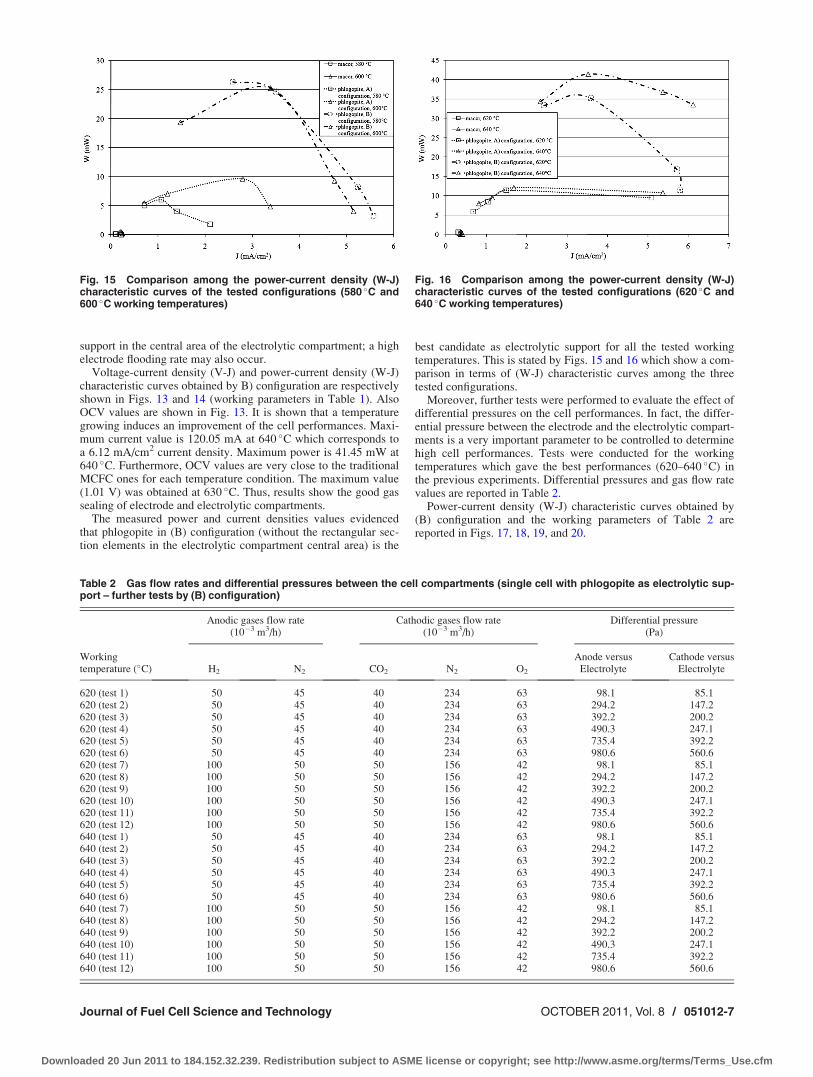
The measured power and current densities values evidencedthat phlogopite in (B) configuration (without the rectangular sec-tion elements in the electrolytic compartment central area) is the
best candidate as electrolytic support for all the tested workingtemperatures. This is stated by Figs. 15 and 16 which show a com-parison in terms of (W-J) characteristic curves among the threetested configurations.
Moreover, further tests were performed to evaluate the effect ofdifferential pressures on the cell performances. In fact, the differ-ential pressure between the electrode and the electrolytic compart-ments is a very important parameter to be controlled to determinehigh cell performances. Tests were conducted for the workingtemperatures which gave the best performances (620–640 �C) inthe previous experiments. Differential pressures and gas flow ratevalues are reported in Table 2.
Power-current density (W-J) characteristic curves obtained by(B) configuration and the working parameters of Table 2 arereported in Figs. 17, 18, 19, and 20.
Fig. 15 Comparison among the power-current density (W-J)characteristic curves of the tested configurations (580 �C and600 �C working temperatures)
Fig. 16 Comparison among the power-current density (W-J)characteristic curves of the tested configurations (620 �C and640 �C working temperatures)
Table 2 Gas flow rates and differential pressures between the cell compartments (single cell with phlogopite as electrolytic sup-port – further tests by (B) configuration)
Anodic gases flow rate(10�3 m3/h)
Cathodic gases flow rate(10�3 m3/h)
Differential pressure(Pa)
Workingtemperature (�C) H2 N2 CO2 N2 O2
Anode versusElectrolyte
Cathode versusElectrolyte
620 (test 1) 50 45 40 234 63 98.1 85.1620 (test 2) 50 45 40 234 63 294.2 147.2620 (test 3) 50 45 40 234 63 392.2 200.2620 (test 4) 50 45 40 234 63 490.3 247.1620 (test 5) 50 45 40 234 63 735.4 392.2620 (test 6) 50 45 40 234 63 980.6 560.6620 (test 7) 100 50 50 156 42 98.1 85.1620 (test 8) 100 50 50 156 42 294.2 147.2620 (test 9) 100 50 50 156 42 392.2 200.2620 (test 10) 100 50 50 156 42 490.3 247.1620 (test 11) 100 50 50 156 42 735.4 392.2620 (test 12) 100 50 50 156 42 980.6 560.6640 (test 1) 50 45 40 234 63 98.1 85.1640 (test 2) 50 45 40 234 63 294.2 147.2640 (test 3) 50 45 40 234 63 392.2 200.2640 (test 4) 50 45 40 234 63 490.3 247.1640 (test 5) 50 45 40 234 63 735.4 392.2640 (test 6) 50 45 40 234 63 980.6 560.6640 (test 7) 100 50 50 156 42 98.1 85.1640 (test 8) 100 50 50 156 42 294.2 147.2640 (test 9) 100 50 50 156 42 392.2 200.2640 (test 10) 100 50 50 156 42 490.3 247.1640 (test 11) 100 50 50 156 42 735.4 392.2640 (test 12) 100 50 50 156 42 980.6 560.6
Journal of Fuel Cell Science and Technology OCTOBER 2011, Vol. 8 / 051012-7
Downloaded 20 Jun 2011 to 184.152.32.239. Redistribution subject to ASME license or copyright; see http://www.asme.org/terms/Terms_Use.cfm
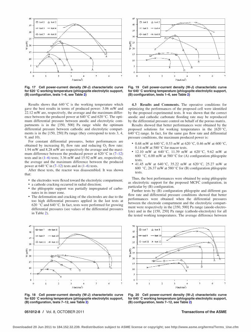
Results shows that 640 �C is the working temperature whichgave the best results in terms of produced power: 3.06 mW and22.12 mW are, respectively, the average and the maximum differ-ence between the produced power at 640 �C and 620 �C. The opti-mum differential pressure between anodic and electrolytic com-partments is in the [350, 500] Pa range while the optimumdifferential pressure between cathodic and electrolytic compart-ments is in the [150, 250] Pa range (they correspond to tests 3, 4,9, and 10).
For constant differential pressures, better performances areobtained by increasing H2 flow rate and reducing O2 flow rate:1.94 mW and 8.28 mW are respectively the average and the maxi-mum difference between the produced power at 620 �C in (7–12)tests and in (1–6) tests; 3.36 mW and 15.92 mW are, respectively,the average and the maximum difference between the producedpower at 640 �C in (7–12) tests and in (1–6) tests.
After these tests, the reactor was disassembled. It was shownthat:
• the electrodes were flexed toward the electrolytic compartment;• a cathode cracking occurred in radial direction;• the phlogopite support was partially impregnated of carbo-
nates in its inner zone.• The deformation and cracking of the electrodes are due to the
too high differential pressures applied in the last tests at620 �C and 640 �C. In fact, tests were performed for growingdifferential pressures (see values of the differential pressuresin Table 2).
4.3 Results and Comments. The operative conditions foroptimizing the performances of the proposed cell were identifiedby the proposed experimental tests. It was shown that the correctanodic and cathodic carbonate flooding rate may be reproducedby the differential pressure control on behalf of the porous matrix.
Results showed that better performances were obtained by theproposed solutions for working temperatures in the [620 �C,640 �C] range. In fact, for the same gas flow rate and differentialpressure conditions, the maximum produced power is:
• 0.68 mW at 640 �C, 0.53 mW at 620 �C, 0.46 mW at 600 �C,0.14 mW at 580 �C for macor tests.
• 12.10 mW at 640 �C, 11.39 mW at 620 �C, 9.62 mW at600 �C, 6.00 mW at 580 �C for (A) configuration phlogopitetests.
• 41.45 mW at 640 �C, 35.22 mW at 620 �C, 25.27 mW at600 �C, 26.37 mW at 580 �C for (B) configuration phlogopitetests.
Thus, the best performances were obtained by using phlogopiteas electrolytic support for the proposed MCFC configuration, inparticular by (B) configuration.
Further tests by (B) configuration phlogopite and different gasflow rate and differential pressure conditions showed that betterperformances were obtained when the differential pressuresbetween the electrode compartment and the electrolytic compart-ment were respectively in the [350, 500] Pa range (anode-electro-lyte) and in the [150, 250] Pa range (cathode-electrolyte) for allthe tested working temperatures. The average difference between
Fig. 17 Cell power-current density (W-J) characteristic curvefor 620 �C working temperature (phlogopite electrolytic support,(B) configuration, tests 1–6, see Table 2)
Fig. 18 Cell power-current density (W-J) characteristic curvefor 620 �C working temperature (phlogopite electrolytic support,(B) configuration, tests 7–12, see Table 2)
Fig. 19 Cell power-current density (W-J) characteristic curvefor 640 �C working temperature (phlogopite electrolytic support,(B) configuration, tests 1–6, see Table 2)
Fig. 20 Cell power-current density (W-J) characteristic curvefor 640 �C working temperature (phlogopite electrolytic support,(B) configuration, tests 7–12, see Table 2)
051012-8 / Vol. 8, OCTOBER 2011 Transactions of the ASME
Downloaded 20 Jun 2011 to 184.152.32.239. Redistribution subject to ASME license or copyright; see http://www.asme.org/terms/Terms_Use.cfm
the produced power at the optimized differential pressure condi-tions and the one at the other tested conditions is 11.63 mW and18.36 mW, respectively, when the working temperature is 620 �Cand 640 �C. For constant differential pressures, better performan-ces are obtained by increasing H2 flow rate and reducing O2 flowrate: 8.28 mW and 15.92 mW are the maximum increase respec-tively obtained when the working temperature is 620 �C and640 �C. However, oxygen (air) flow rate has to be slightly higherthan the stoichiometric value to obtain better performances.
Some different problems were also found, such as deformationsand cracking of the electrodes, particularly the cathode, whengauge pressures were too high (anode-electrolyte differential pres-sure over 800 Pa and cathode-electrolyte differential pressure over400 Pa); thus, the control of gauge and differential pressures hasto be very accurate. Furthermore, the electrolyte management inthe working and power-off phases and the introduction of the car-bonates in the cell are very sensitive phases.
Further tests are going on in order to solve the mentioned prob-lems; they will also be useful to determine adjustments for identi-fying the optimum electrolyte layer thickness and increasing thecell performances in the best proposed configuration.
5 Conclusions
In this paper, a novel MCFC configuration which does notinvolve the porous matrix was investigated and tested by a cylindri-cal single cell facility. Electrolytic supports made by macor andphlogopite were proposed and tested: the aim was to give to the cellthe same mechanical stability and electrical insulation properties ofa traditional MCFC with lower fabrication costs. Differential pres-sures between the electrode and the electrolytic compartments werecontrolled by a specific system in order to have the same floodingrate of a traditional cylindrical MCFC [3–6]. Experimental resultsshowed the suitability of the proposed solutions: in particular, morepromising performances were obtained by the phlogopite support,thanks to its electrical insulation properties combined with its corro-sion chemical resistance and its mechanical stability. The manage-ment of the liquid electrolyte, given by a specific system which con-trols the gauge pressure of each cell compartment, was optimizedfor the [620 �C, 640 �C] temperature range and for a differentialpressure between the anodic compartment and the electrolytic com-partment in the [350, 500] Pa range. Adjustments have just to be
found to limit electrode deformations or cracking phenomena (espe-cially for the cathode). These are mainly due to the pressure controlsystem which has to be very accurate also to reduce the electrodeflooding rate. However, the good compatibility of the proposed elec-trolytic supports with the proposed configuration suggested to per-form further experimental tests to reduce the mentioned problems:these tests are actually going on. Furthermore, the electrolyte layerthickness and the distance between the electrodes were chosen inorder to assure the cell facility working and a simple installation ofthe electrolytic support materials. In this way, the main purpose ofthe proposed investigation, that is to verify the suitability of thetested electrolytic support materials, was obtained. However, thedistance between the electrodes, the thickness of the carbonate layerand the cell configuration have to be optimized in order to increasethe cell power production performances and evaluate the cell lifeperformances, its suitability for lCHP fuel cell applications and itsviability for industrialization processes: it will be the topic of futureinvestigations which will be made after identifying a definitive solu-tion as electrolytic support disk. Thus, the obtained results may beconsidered as the first step toward the development of the proposednovel MCFC typology.
References[1] Fuel Cell Handbook, 2004, 7th ed., EG&G Technical Services, Parsons.[2] Baker, B., Benedict, M., Bernard, R., Chamberlin, R., Doyon, J., Maru, H.,
Mahoney, J., Paetsch, L., Patel, P., and Pigeaud, A., 1983, “Development ofMolten Carbonate Fuel Cell Technology”, Technical Progress Report.
[3] Italian Patent, PG2003A0019, 2003.[4] Rossi, F., and Nicolini, A., 2009, Fuel Cells 9(2), pp. 170–177.[5] Cotana, F., Rossi, F., and Nicolini, A., 2004, J. Fuel Cell Sci. Technol. 1(1),
pp. 25–29.[6] Cotana, F., Rossi, F., and Nicolini, A., 2003, Proc. First International Confer-
ence on Fuel Cell Development and Deployment, Storrs, CN.[7] Cho, J. Y., Hyun, S. H., and Hong, S. A., 2001, J. Am. Ceram. Soc., 84(5)
pp. 5–12.[8] Rossi, F., Di Matteo, U., and Nicolini, A., 2006, Proceedings of Fuel Cell
2006 Seminar, Honolulu, HI.[9] McPhail, S., Moreno, A., and Bove, R., 2009, International Status of Molten
Carbonate Fuel Cell (MCFC) Technology, ENEA Report RSE/2009/181.[10] Kim, S. D., Hyun, S. H., Shin, M. Y., Lim, T. H., Hong, S. A., and Lim, H. C.,
2005, J. Power Sources, 143, pp. 24–29.[11] Yuh, C., Farooque, M., Johnsen, R., ERC, 1992, Proc. of the Fourth Annual
Fuel Cells Contractors Review Meeting, U.S. DOE/METC, and 2002 FCEcorrespondence.
[12] C. J. R. Verbeek, 2002, Mater. Lett., 56 (3) pp. 226–231.
Journal of Fuel Cell Science and Technology OCTOBER 2011, Vol. 8 / 051012-9
Downloaded 20 Jun 2011 to 184.152.32.239. Redistribution subject to ASME license or copyright; see http://www.asme.org/terms/Terms_Use.cfm